Article

The Effect of External Geometry Factors on the Characteristics of Flow Profiles and Segregation in a Vertical Sinter Cooling Bed

Department of Thermal Engineering, State Environmental Protection Key Laboratory of Eco-Industry, School of Metallurgy, Northeastern University, Shenyang 110819, China
*
Author to whom correspondence should be addressed.
Energies 2020, 13(22), 5964; https://doi.org/10.3390/en13225964
Submission received: 2 October 2020 / Revised: 6 November 2020 / Accepted: 11 November 2020 / Published: 16 November 2020
(This article belongs to the Section B: Energy and Environment)

Abstract

:
Good particle flow patterns and uniform particle velocity distributions enhance the performance of heat transfer and smooth flow processes in vertical sinter cooling beds (VSCBs). The effect of three typical geometries, conical, curved and rectangular, on the performance of flow profiles and segregation in a VSCB is investigated comparatively and quantitatively based on the discrete element method (DEM). The evolution of flow profiles and particle segregation directly influence the evenly distributed sinter layers and the efficiency of heat exchange in VSCBs. In this research, a 3D packed bed model is established for the three geometry types to quantitatively and qualitatively investigate the influence of structural parameters on the evolution of flow patterns and segregation. The comparison of the effect of the three geometry types on the particle flow process showed that the curved geometry types greatly improve the performance of the flow pattern and size segregation. The height of the mass flow pattern for the curved geometry varies with the structural parameters by 1.5-fold that of the flow pattern for the other two geometry types. The curved geometry dramatically reduces the magnitude of the segregation index (SI) near the sidewall, while this magnitude fluctuates near 1.0 in the central flow passage of the VSCB.

1. Introduction

Many types of vertical beds are applied to assist the production process in the iron and steel industry, such as blast furnaces [1], CDQs (coke dry quenches) [2], pelletizing furnaces [3] and lime shaft furnaces [4]. The vertical sinter cooling bed (VSCB) is considered a typical vertical packed bed of a waste heat recovery device for reducing the temperature of the hot sinter from the sinter machine to provide raw material under a defined temperature for the next production process in a steel factory. During recovery, the sensible heat from the blazing sinter ore process manages for effectiveness in reducing the energy consumption of the production process and for lessening the negative effect on the environment. In previous research, scholars mainly examined the effect of several parameters on the performance of heat transfer and hydrodynamics with gas flow. Studies frequently ignore the evolution of bulk solid flow profiles in VSCBs, and the even particle flow distribution in sinter layers is a basic improvement in the performance of heat transfer in VSCBs. Therefore, the influence of the factors affecting smooth sinter particle flow in bulk layers is the crux of the heat transfer process in VSCBs. This result should proceed from multiple influential factors, including the particle distribution, external geometry and properties of the bulk solid. In particular, few researchers have focused on a systematic investigation of the effect of variations in external geometry on the characteristics of sinter particle flow profiles and segregation in VSCBs. More attention has been given to investigating the external geometry factors that possess more advantages than the properties of bulk solids because remoulding the external geometry factors is more useful and reliable for actual production.
Few research efforts have been made on improving the performance of heat transfer between air and sinter granules by optimizing the variation of flow profiles in the sinter layers’ impact on the heat exchange process. However, many papers uncover the influence of typical structural parameters on the improvement in the flow pattern and enhancement of smooth flow discharge in different research domains. To study the effect of the geometry of the packed bed on granular material flow profiles, Mellmann [5] found that the Froude number has a negative correlation with the parameter of the outlet geometry in agricultural bulk material, and Laroe [6] uncovered the effect of the diameter of the cross section of the circular vertical pipe on the variation in the particle velocity profiles in the food production process. Merwe [7] revealed the effect of the structure of the packed bed on the flow pattern in nuclear engineering. Qian [8] researched the influence of the structure of the grille-sphere composite of the packed bed on the performance of chemical reactions and heat transfer in chemical engineering. Babout [9] studied the effect of the structure of a silo on the particle discharge process in transportation granular material. Zaki [10] investigated the effect of the structure of a flat-bottomed cylindrical silo on the mass flow rate and flow velocity distribution for different outlet shapes with the help of DEM-based open-source software. Zhang [11] analysed the flow pattern transition affected by the structural parameters of a silo for storing grain material. Liu [12] studied the effect of curved geometry hoppers with different contraction rates on the particle discharge flow with the help of the DEM method. Xu [13] introduced the particle size distribution on the particle segregation during the charging process in the sintering process with the help of DEM model. Huang [14] studied the particles segregation in rotating drum under the variation of internal diameter conditions with the aid of DEM model. Yang [15] used the DEM model to investigate the binary mixture of non-spherical particles shear flow during the granular matter flow process and considered the effect of shapes and volume fraction ratio on the shear stress and granular matter flow profiles. Govender [16] investigated the effect of irregularly shaped particles with help of GPU-based DEM model and experimental testing on the granular flow in hopper. Ma [17] studied the effect of ellipsoidal geometry type of granular particles in the horizontal rotating on the flow pattern with help of DEM model. Qiu [18] investigated the particle flow profiles in the type of parallel-hopper bell-less charging and mono-sized particles in blast furnace, considering the significant particles flow features including the contact force chains, flow patterns, velocity distribution, stress distribution and wall pressure.
Although a number of research papers published in the last decade have focused on the performance of waste heat recovery in VSCBs, no scholars have considered the effect of the external geometry structure on improving the particle flow pattern in VSCBs. In this paper, with the help of the DEM, three-dimensional mathematical models of the three geometry types of VSCBs are established. By comparison, the external geometry factor influences on the particle flow profiles and size segregation are examined quantitatively and systematically. The effects of structural parameters, including the normalized outlet, half hopper angle and geometry factor, of the three geometry types on the characteristics of sinter layer flow behaviour, such as the velocity distribution, stabilization of particle flow profiles, mass flow pattern, smooth particle flow process and particle size segregation, are quantitatively and comparatively studied. The differences in the three geometry types for performing particle flow profiles and segregation during the continuous flow process are quantitatively and qualitatively presented.

2. Simulated Methodology

2.1. DEM Method

The DEM (discrete element method) is extensively used to solve the dynamic flow characteristics of powder materials and was developed by Cundall and Strack [19], who dissected the integrity of domains into several discrete elements containing different shapes and particle masses. A three-dimensional model of the DEM is used to describe the characteristics of sinter particle continuous flow in a vertical moving packed bed containing two distinct types of motion, namely, translational and rotational motion. The translational and rotational flow motion behaviour of sinter particles in discrete elements is dominated by Newton’s law, which describes the evolution of force and displacement in the particle motion process as follows:
Translational motion:
m i d v i d t = m i g + i = 1 n i ( F c n + F d n + F c t + F d t )
Rotational motion:
I i d ω i d t = i = 1 n i ( T t , i j + T r , i j )
The Hertz-Mindlin [20,21] contact model is used to perform the dynamic particle flow in the discharging process, and the force and torque between the particles and between particles and objects is determined by the no slip Hertz-Mindlin model. Moreover, the variation in force and torque in tangential and normal flow directions is governed by Mindlin-Deresiewic’s theory [22] and Hertz’s theory [23], respectively. For the presentation of the evolution of forces and torques of sinter particles in the granular flow process, the description of the control equations is presented in Table 1.
Where E* = E/2(1 − υ2), 1/m* = 1/mi + 1/mj, 1/r* = 1/ri + 1/rj, 1/G* = (2 − υi)/Gi+ (2 − υj)/Gj, vij= vivj + ωj × rijωi × rij, St = 8G* r δ n , Sn = 2E* r δ n .

2.2. Characteristics of the Geometry Types of VSCBs

To investigate the different external geometries influencing the characteristics of flow profiles in the VSCB, the three geometry types of VSCBs are considered in this research, namely, circular, rectangular and curve geometry types. Moreover, the differences in the structural characteristics of the three geometry types are considered to comprehensively understand the mechanism of the effect of the external geometry factors on the flow profiles during continuous operating conditions in VSCBs.
This research mainly focuses on three geometry types of VSCBs, namely, circular types, rectangular types and curved types. The characteristics of the three types of VSCB geometries are described as follows: the circular type is comprised of a cylindrical and circle hopper section, and the half hopper angle remains constant with a decrease in the height of the hopper. The contraction rate of the hopper gradually decreases with a decrease in the height of the hopper. The rectangular geometry type of the vertical packed bed, which is comprised of a rectangular cylindrical and hopper, shares a similar trend in the variation of the structures of the half hopper angle, contraction rate and flow passage cross section. The contraction rate of the curve types remains constant, and the half hopper angle gradually increases as the height of the curved hopper varies.
The curved geometry type is totally distinct from the circular and rectangular geometry. Therefore, it is necessary to present the peculiarity of the structures in detail. The mathematical description of the curved geometry type is as follows:
The characteristics of the contraction rate vary with the cross section,
s 1 s 2 s 1 d y = d s s 1 d h = 2 π r d r π r 2 d h = a C
where s1, s2 is the area of the cross section, r is the radius of the cross section, ds is the area of cross section decrease in quantity, C is the contraction rate, dh is the minimal height of the particles drop, a is a coefficient for the shape of the cross section (for a circular cross section, a = 1) and C is the contraction rate.
For the calculation of the contraction rate of the cross section, the contraction rate of the curved hopper varies with the height of the packed bed’s cross section. The calculation of the contraction rate is as follows: evaluating the integral from 0 and H on the right side of Equation (3) and the integral from r0 and r on the left side in Equation (3) obtains:
r = r 0 e c 2 h
C = 2 H ln ( D 0 / d 0 )
where h is the height of the calculated packed bed, H is the height of the curved hopper, r0 is the radius of the outlet of the curved hopper, r is the radius of the calculated cross section, D0 is the diameter of the inlet of the curved hopper, and d0 is the diameter of the outlet of the curved hopper.
The half hopper angle of the curved hopper varies with the cross section at different heights of the hopper:
d h d r = tan ( 90 ° α ) = 2 C r
The transformation of Equation (4) is used to describe the variation in the half hopper angle as follows:
α = 90 ° arctan ( 2 C r )
where r is the radius of cross section in the hopper section, C is the contraction of the curve geometry.

2.3. Experimental Packed Bed and Method

Figure 1 shows a schematic diagram of the three geometry types of the vertical moving packed beds. Two distinct sections comprise the packed bed, namely, cylindrical and hopper sections. A circular cylindrical and hopper compose the rectangular geometry type (Figure 1a), a rectangular cylindrical and hopper compose the circular geometry type (Figure 1b) and a circular cylindrical and curved hopper compose the curved geometry type (Figure 1c). The packed bed is built with a steel frame. A prechamber built on top of the cylindrical section is applied to circulate in charging sinter particles, and the sinter particles used in the experiment stem from the steel plant. The discharge system comprises an electromagnetic vibrator and rotary seal valve and is used to operate the stabilization and uniformity discharge in the sinter layers. The measuring mass flow system contains an industrial electronic scale with a digital panel connected to a computer with professional software used to record the collected data and calculate the discharge process in real time.
The sinter particles are poured from the pre-chamber into the packed bed and the discharge system operates to export particles simultaneously. The variation in the characteristics of the flow profiles depends on the different structures of the packed bed and particle flow across the packed bed under distinct flow profiles. In the continuous charging and discharging process, the variation in the mass flow of sinter particles is automatically monitored and recorded by a weight scale and computer analysis system.
The Sauter mean diameter (SMD) is usually used to present the industrial particle distribution for the actual granular particle distribution of granular materials of multiple diameter ranges. The equation for the SMD is described as follows:
d e , i = 1 / k n m f ( w i , k / d k )
where de,i is the SMD particle distribution, wi,k is the weight of the mass percent of group size i with a dk average particle diameter, and nmf is the number groups of granular size distributions. dk is the mean geometrical particle distribution, dk = d l d h , where dl and dh are the lower and higher values of the particle distribution in group size i, respectively. The particle diameter distribution in this research is subjected to a lognormal distribution. The average particle diameter is 20 mm, and the standard deviation of the lognormal distribution is 0.5. The equation for the particle diameter distribution is expressed as [24]:
f = 1 d S M D σ 2 π exp [ ( ln ( d S M D ) μ ) 2 2 σ 2 ]
where f is the emergence of the frequency of the particle diameter, dSMD is the Sauter mean diameter size distribution, σ is the standard deviation of the particle size distribution, and μ is the average of the particle size distribution.

2.4. Quantitative Description of Particle Flow and Segregation Behaviours

2.4.1. The Flow Profiles for Particle Layers

This research mainly focuses on the particle flow profiles in sinter layers based on the variation in the velocity distribution of particle layers with the help of the DEM method. The mathematical description of the velocity distribution in discrete elements is presented as macroscopic behaviour for the quantity of blocks of particle dynamic motion. The velocity distribution of the particle layers is given in Equation (10), with the variation in velocity in the z direction as the research object.
v z = i = 1 n v i n
where vz is the mean velocity in the element in the z direction, i is the ith discrete element, n is the total number of elements, and vi is the velocity distribution of the ith element.
Moreover, the average velocity distribution in particle layers is expressed as follows:
v a v e , j = k = 1 m v z , j k m
where vave,j is the average velocity of the jth particle layer, vz,jk is the mean velocity in the jth layer and kth column in the z direction, and m is the total number of columns in the particle layers for the numerical model.
Furthermore, the mass flow index (MFI) is introduced in the research to determine the variation in the particle flow pattern transition with the structure of the packed bed. The MFI is a criterion parameter that quantitatively and qualitatively describes the evolution of the particle flow pattern based on the comparison of the contrast between the velocity distribution in the central and sidewall sections of the moving packed bed. The MFI parameter is defined as the ratio of vw and vc as follows.
M F I = v w v c
where vw is the velocity in the sidewall and vc is the velocity near the central section.

2.4.2. The Variation in Segregation for Particle Layers

To further analyse the variation in particle size, the segregation in the sinter layers is varied with the external structures of the moving packed bed. The SI (segregation index) is introduced as the ratio of the calculated Sauter mean diameter (SMD) and the corresponding value of the initial performance for multiple size distributions in particle samples. In previous studies, there are many defined segregation indices dependent on different physical parameters, including the mass and number fraction of small particles, average particle diameter and relative particle size, which are more reliable and reasonable for binary or triple size particle mixture samples, which are not applicable to describing the characteristics of variation in segregation with multiple particle size distributions. The segregation index based on the variation in the SMD in sinter particle layers is determined as the ratio of de,i to dm,i:
S I = d e , i d m , i
where de,i is the calculated SMD of the particle size in each element according to the DEM simulated results and dm,i is the initial designed value of the SMD of the particle size.

3. Validation Model

Because the VSCB is a confined structure, it is considered a “black box”, which has difficulty observing the internal variation flow profile without an operation to destroy the structure of the packed bed. Therefore, a macroscopic physical parameter is defined as a standard for determining the internal evolution of the particle flow profiles in the packed bed without a negative influence on the particle flow pattern during the continuous discharge process. The mass flow rate is selected as the criterion parameter for determining the reliability and accuracy of the calculation results with data from experiments. Table 2 presents the physical parameters used in the numerical process. The parameters obtained from testing experiments and published literatures, the Young’s modulus and Poisson’s ratio are obtained from the modified parameter from literatures [25]; the restitution between sinter particles is obtained from the double pendulum method; the restitution of sinter particles and wall is obtained from the dropping testing method; the friction between sinter particles and sinter particles and wall are obtained from uniaxial compressive testing method; the rolling friction between sinter particles and sinter particles and wall are obtained from the tilt passage testing method, the variation of friction between particles and particles with help of pasting the different diameter of sinter particles on the tilted plate. In order to validation for the reliable of simulation, two types vertical sinter packed bed are built which including the circular and rectangular sinter packed bed, the hopper section is design as interchangeable model. In the different conditions of varies with half hopper angle, the tested recording of mass flow rate with the results of simulation. The sinter particles are pouring through the filling device into the silo until the designed filling height of sinter layers is obtained. In order to require the steady initial state, the sinter layers are designed in the quasi-static situation for the dynamic energy of sinter particles less than 10−7 J and the magnitude of velocity is less than 10−5 m·s−1. When the condition of steady initial state required, the discharge process is commenced to initiate with the outlet port opened. The discharge mass of sinter particles is filling in twenty wood made of boxes under the sinter outlet port, the volume of wooden box is 0.027 m3, the interval of the discharge particles drop in each box is 2 s. In order to guarantee the testing for the weight of discharged sinter particles in each box, the box is interchangeable arranged on the top panel of trailer, the trailer is pulled by manpower under the condition of uniform velocity moving along the horizontal direction. The mass of sinter particles in each box is recorded by weight digital scaler.
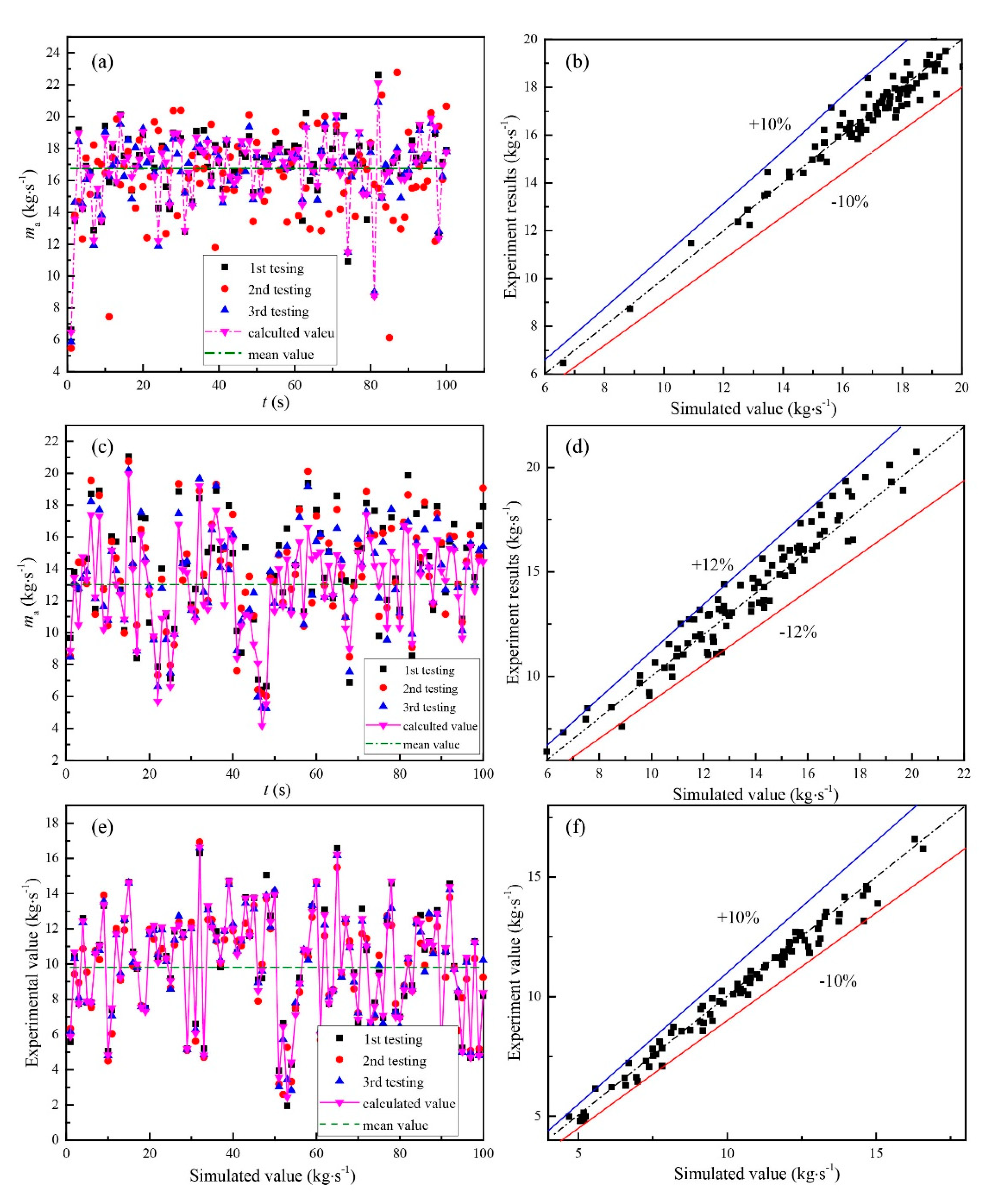
Figure 2 compares the calculated Froude number with the experimental results for the three geometry types with different configurations of the hopper sections. The Froude number is derived from the average mass flow rate (MFR) of the three geometry types of VSCBs, and the MFR has a positive effect on the Froude number, which varies with particle flow profiles. The equation for the correlation of the Froude number and mass flow rate is described according to the research of Lehmann [26] as follows:
F r = m a ρ b g 0.5 d 0 2.5
where ma is the average mass flow rate, ρb is the bulk density, g is the gravitational acceleration of the object, and d0 is the outlet of the packed bed. The variation in the Froude number gradually decreases with increasing half hopper angle for circular and rectangular geometry types and the contraction rate with the initial angle. The figure shows that the difference between calculation and measurement is very small, and the corresponding value of the relative error is less than 7%. The evolution of the relative error in the calculated Froude number with the half hopper angle is described as follows.
e = 1 n i n | ( f c a l , i f exp , i ) / f exp , i | × 100 %
where e is the relative error, n is the total number of measured samples, fcal,i is the data for ith calculation, and fexp,i is the ith experimental result.
Figure 2 shows the comparison of the mass flow rate between tested and simulated value, the main variation of the mass flow rate of three types geometry is fluctuated around the mean value for mass flow rate, because of the sinter particles discharge experiences the emergency and destruction of bulk arch process, the fluctuation of magnitude of mass export and the amplitude of the magnitude of mass flow rate increase with the frequency of the emergency of bulk arch. It can be seen from Figure 2, the fluctuation of mass flow increase in the types of rectangular and circular geometries. The mean value of mass flow rate for three types of geometry is 16.4 kg·s−1, 12.6 kg s−1 and 9.8 kg s−1, respectively. The error of the mass flow rate between experimental value and calculated value is 7.26%, 8.74% and 6.87%, respectively according the calculation with the Equation (15).
Figure 3 also shows the nonlinear fitting curve of the experimental results with the experimental error for the three geometry types, and the of the difference between the simulated and experimental results shows that the numerical model is in good agreement and has reliability for the subsequent research work to be presented as follows.

4. Results and Discussion

4.1. Effect of the Three Geometry Types with Different Normalized Outlets on Flow Profiles (d0/D0)

4.1.1. Velocity Distribution of the Sinter Layers for the Three Geometry Types with Different Outlets Normalized (d0/D0)

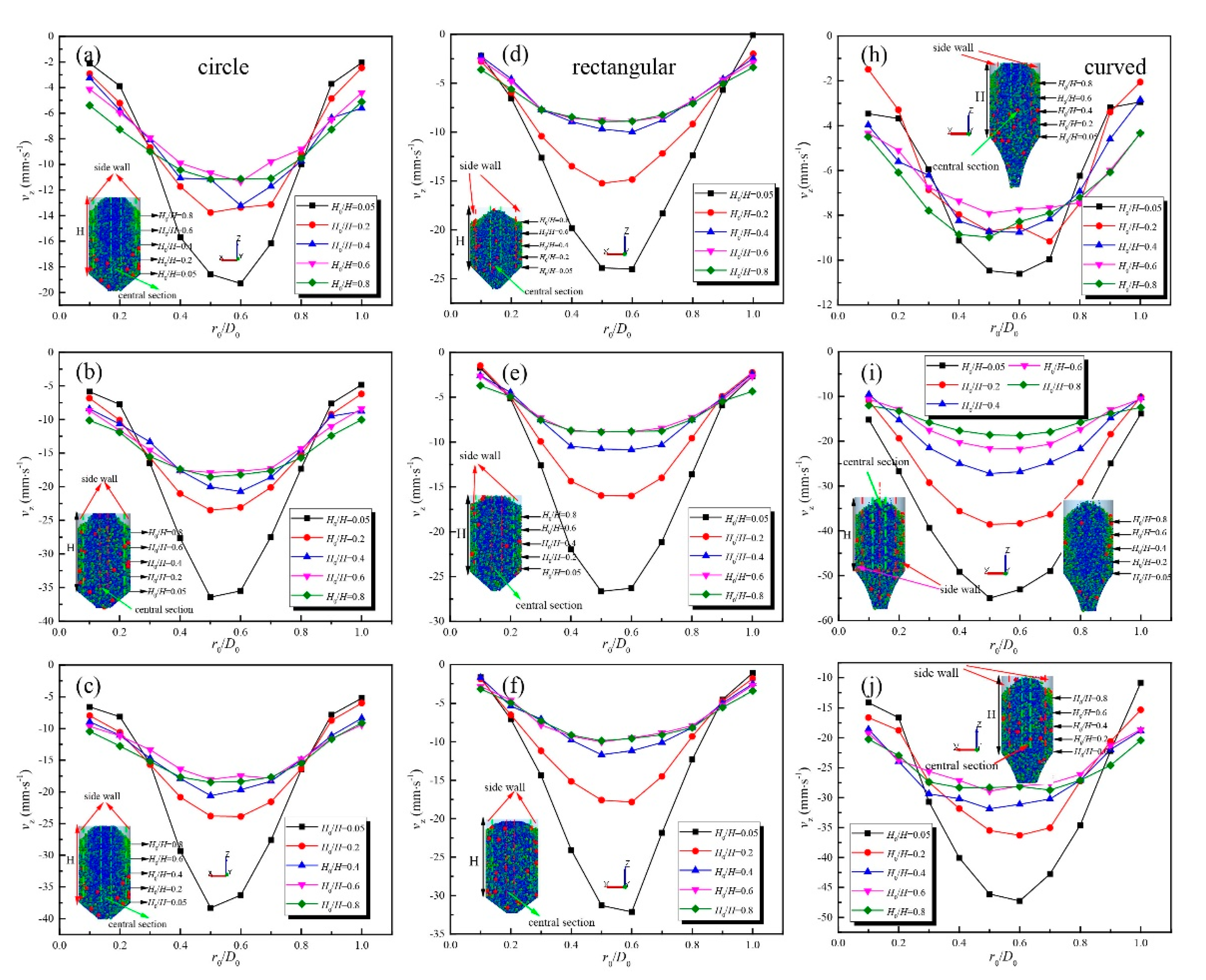
Figure 4 shows the variation in the velocity distribution in the comparison of the three geometry types of the VSCB (Figure 4a–c) for the circular type, (d)–(f) for the rectangular type, and (g)–(i) for the curved type) with different normalized outlets (0.2–0.4) as a function of the dimensionless height of the packed bed. There are two different sections for the evolution of the velocity distribution in the packed bed, namely, the sidewall section and central section. The overall trend of the velocity distribution for the three geometry types of the VSCB with different normalized outlets (d0/D0) shows that the magnitude of the velocity near the sidewall gradually decreases with a decrease in the dimensionless height of the packed bed, while the corresponding value of the velocity increases sharply with a decrease in the dimensionless height of the packed bed in the central section. The increasing rate of the magnitude of the velocity in the central parts dramatically increases between the normalized outlet in 0.2 and 0.3, and then the corresponding figure deeply decreases with an increase in the normalized outlet for all three geometry types of the VSCB. The circular (Figure 4a–c) and rectangular (Figure 4d–f) geometry types of the VSCB are almost identical in the difference between the magnitude of the velocity in the central section sharply increasing with the normalized outlet increase, while the corresponding value of the velocity near the sidewall gradually increases for the circular geometry type bed and remains constant for the rectangular geometry type bed with an increase in the normalized outlet. For the curved (Figure 4h–j) geometry type of the VSCB, the difference in the magnitude of the velocity between the central and sidewall sections gradually decreases, while the corresponding value of the velocity deeply increases with increasing normalized outlet.

4.1.2. MFI of Sinter Layers for the Three Geometry Types with Different Outlets Normalized (d0/D0)

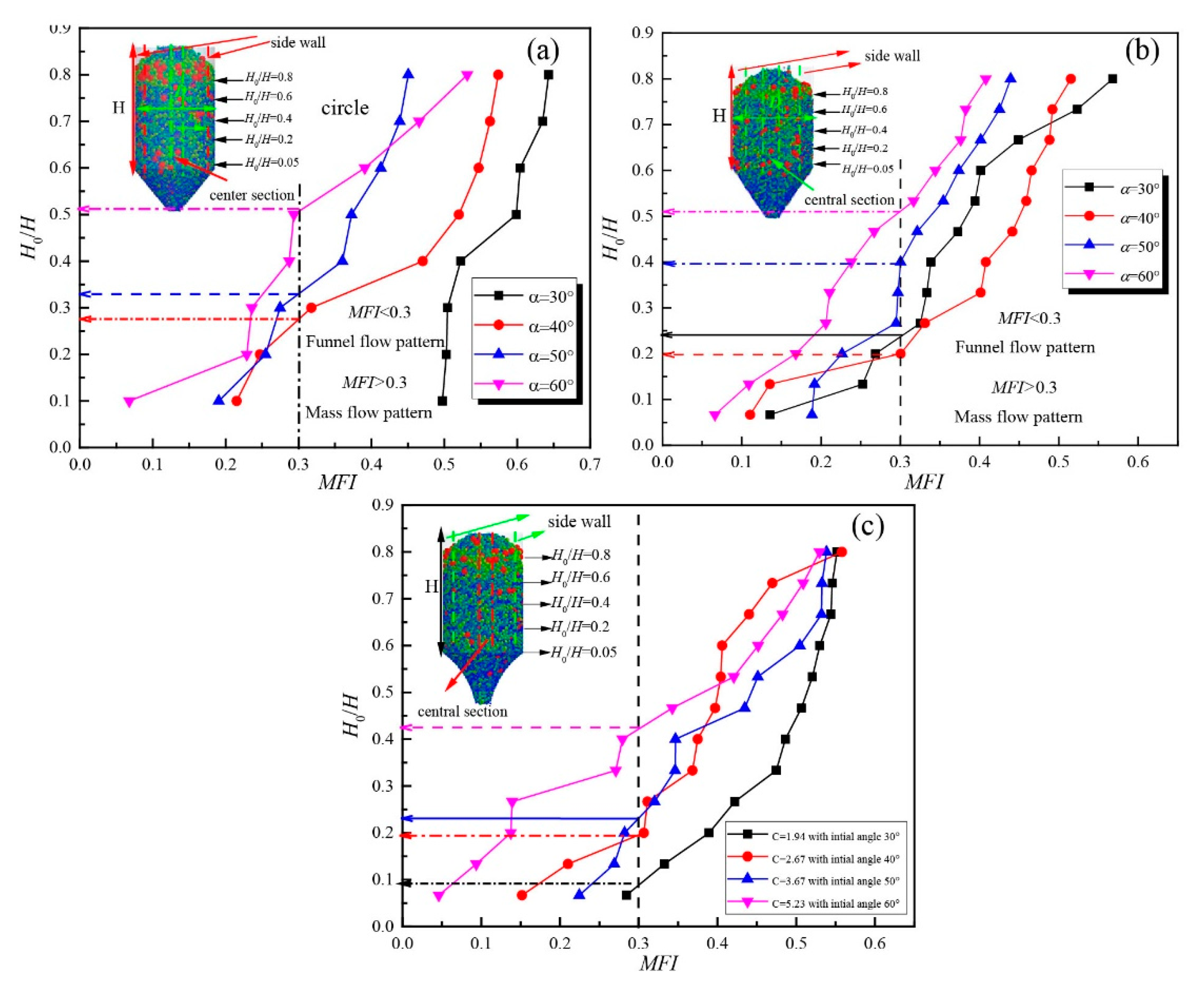
To analyse the dynamic evolution of the flow pattern in sinter layers, the mass flow index (MFI) is extensively employed to display the variation in the transition of the particle flow pattern in powder material layers. The MFI is considered a macroscopic criterion (MFI > 0.3 is the mass flow pattern, MFI < 0.3 is the funnel flow pattern) for determining the parameter for performing a block of particle flow dynamics behaviour instead of the flow characteristics of single particles. Figure 5 demonstrates the variation in the MFI for the three geometry types of VSCBs with different normalized outlets as a function of the dimensionless height of the vertical packed bed. There is a transition point at which the particle flow pattern transforms mass flow into a funnel flow pattern. The dimensionless height of the mass flow slightly decreases with the normalized outlet increase for the circular geometry type of the VSCB (Figure 5a). The variations in the magnitude of the MFI for the normalized outlet in 0.3 and 0.4 are almost identical. The disparities between the magnitudes of the dimensionless height of the vertical packed bed for the normalized outlet in 0.2 and 0.3 are very small. Figure 5b reveals the characteristics of the variation in the transition of the particle flow pattern for different normalized outlets for the rectangular geometry type of the VSCB. The dimensionless height of the transition point gradually increases with an increase in the normalized outlet. The height of the mass flow pattern decreases with an increase in the normalized outlet, which has a negative influence on the particle flow pattern for the rectangular geometry type of the VSCB. Figure 5c shows that the curved geometry type has a positive influence on the flow pattern throughout the particle layers compared to the previously mentioned two types of structures. Notably, the optimal condition for the performance of the flow pattern, the normalized outlet in 0.3, and the mass flow pattern are obtained in all sinter layers. For the transition of the height of the sinter layer in the normalized outlet in 0.4, the trend is mirrored in the variation in the transition point with the normalized outlet in 0.2. Evidently, the sustainable increase of the normalized outlet, which surpasses the optimal value, has an adverse effect on the particle flow pattern for the curved geometry type of the VSCB.

4.2. Effect of the Three Geometry Types with Different Half Hopper Angles on Flow Profiles

4.2.1. Velocity Distribution of Sinter Layers for the Three Geometry Types with Different Half Hopper Angles

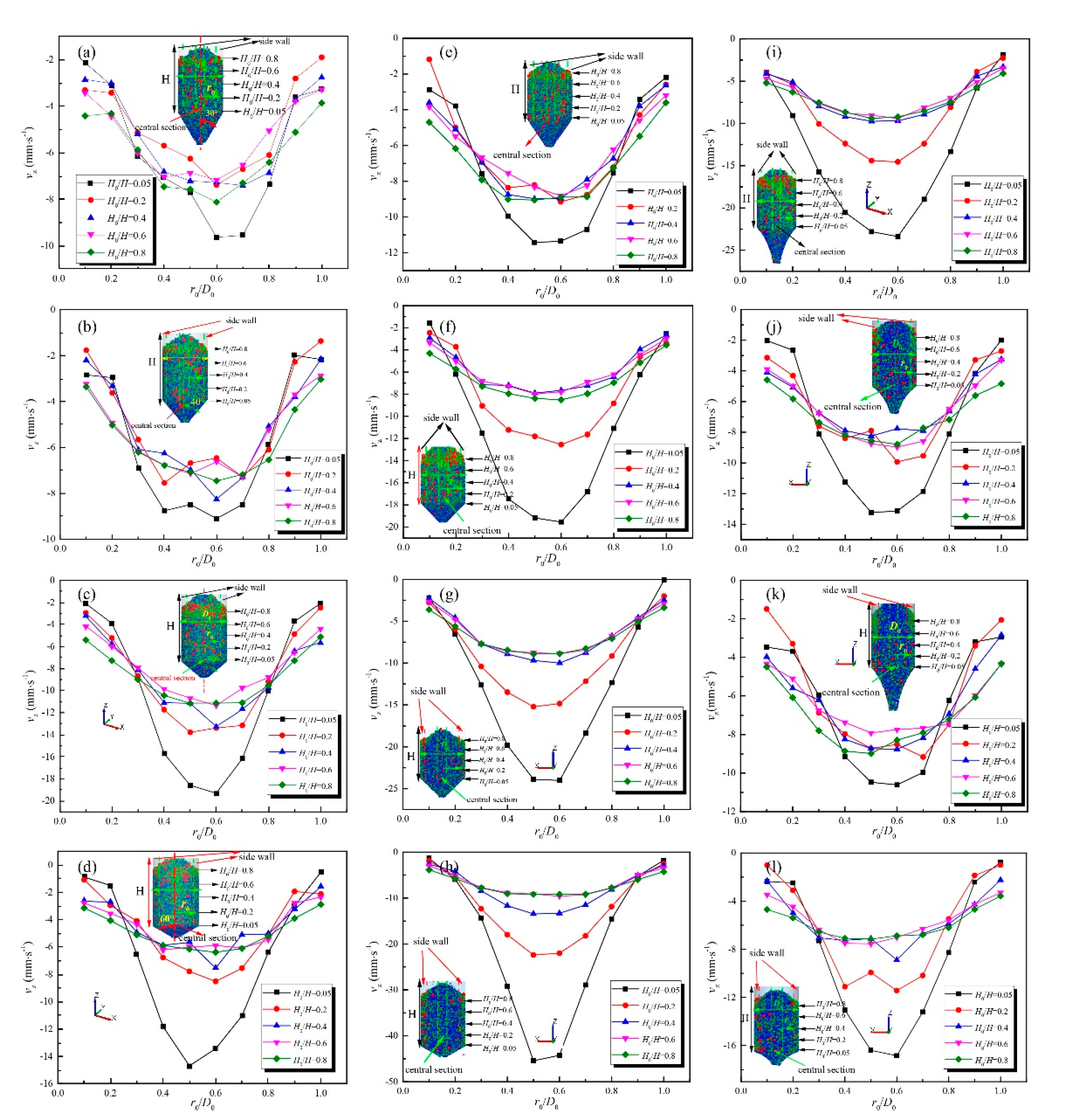
Figure 6 displays the variation in the velocity distribution for the three geometry types with different half hopper angles. Notably, different initial angles possess identical values of the half hopper angle for the circular and rectangular geometry types for curved geometry type, which leads to the contraction rate increasing with the half hopper angle. Figure 6 also reveals two distinct characteristics of the variation in the velocity distribution for the three geometry types. The magnitude of the velocity distribution increases substantially with the half hopper angle in the central section, and the corresponding value gradually decreases near the sidewall for the circular and rectangular geometry types. However, the difference in the magnitude of the velocity distribution between the central and sidewall sections significantly increases with the half hopper angle. Figure 6a–d shows that the magnitude of the velocity continues to accelerate between half hopper angles of 30° and 50°, and the corresponding value slightly decreases with a continuous increase in the half hopper angle in the central section for the circular geometry type. The influence of the resistance of the hopper mainly on the velocity distribution near the sidewall is obvious and promotes particle flow growth in the centre between half hopper angles of 30° and 50°. With the half hopper angle increasing onwards, the effect of the resistance of the hopper on the velocity distribution in both sections along the radius direction decreases. Regarding the rectangular geometry type (Figure 6e–h), the trend is mirrored in the variation in the velocity distribution in the sinter layers between half hopper angles of 30° and 50°. The magnitude of the velocity in the central section dramatically increases as the half hopper angle continues to increase. Evidently, the effect of the resistance for the structure of the hopper is only on the particle flow near the sidewall while promoting sustainable acceleration of the particle flow velocity in the central section. Regarding the velocity distribution for the curved geometry type, its magnitude is gradually decreased in the central section, while the corresponding value remains stable near the sidewall between initial angles of 30° and 50°. The results show that the difference in the velocity gradually decreases because of the resistance of the structure of the hopper, which leads to the mass flow rate of the sinter layers being reduced with an increasing contraction rate. As the contraction rate continues to increase, the variation in the velocity distribution presents an opposite trend in the particle flow velocity along the radius direction. The value of the velocity increases in the centre and the corresponding value decreases near the sidewall, which leads to a greater disparity in velocity distribution between the central and sidewall sections.

4.2.2. MFI of Sinter Layers for the Three Geometry Types with Different Half Hopper Angles

Figure 7 presents the evolution of the MFI for the three geometry types with different half hopper angles along the height direction. Figure 7a shows the variation in the MFI as a function of the dimensionless height for the circular geometry type. The magnitude of the MFI gradually increases with the half hopper angle. The height of the flow transition greatly increases with the half hopper angle, which demonstrates that the height of the mass flow pattern sustainably decreases with increasing half hopper angle. There is a negative effect on the flow profiles in the VSCB with increasing half hopper angle for the circular geometry type. Figure 7b shows that the MFI undergoes a slight decrease and the flow pattern transition height of packed bed undergoes a sustainable increase between the half hopper angles of 40° and 60°. Figure 7b also presents the situation of half hopper angles of 30° and 40° sharing the same trend in the variation in the MFI along the height of the packed bed, while the difference between the height of the mass flow pattern at half hopper angles of 30° and 40° is slight. Figure 7c reveals that the magnitude of the MFI undergoes a modest decrease and that the height of the flow pattern transition dramatically increases with the increase in the initial angle for the contraction rate. The results show that there is a negative effect on the flow pattern with the increase in the initial angle for the contraction rate. Figure 7 compares the evolution of the MFI for the circular, rectangular and curved geometry types between half hopper angles of 30° and 60°. The curved geometry type greatly improves the flow pattern in the packed bed by enhancing the height of the mass flow pattern. A smaller contraction rate with a lower initial angle is beneficial for improving the performance of the flow pattern and enhancing the mass flow rate for curved geometry types.

4.3. Effect of the Three Geometry Types with Different Geometry Factors on Flow Profiles (D0/dp)

4.3.1. Velocity Distribution of Sinter Layers for the Three Geometry Types with Different Geometry Factors

To analyse the effect of the geometry factor on the velocity distribution for the three geometry types under the same conditions, the cylindrical section remains at an identical volume for all geometry types, the normalized outlet shares an identical value in the three geometry types and the height of curved hopper is identical for the different geometry factors, leading to the curved hopper having a constant contraction rate in the calculation. Figure 8 presents the evolution of the velocity distribution for the three geometry types with different geometry factors. The circular and rectangular geometry types share a similar trend in the velocity distribution in the sidewall and central section: the magnitude of the velocity greatly increases, the rate of increase of velocity gradually decreases with the geometry factor increase in the central section, and the corresponding value in the sidewall gradually decreases with an increase in the geometry factor. In terms of the variation in velocity with the dimensionless height of the sinter layers, the same pattern is observed when the velocity distribution varies with the geometry factors. Regarding the evolution of the velocity in the curved geometry type for different geometry factors, the magnitude of the velocity on the sidewall and central section gradually increases with the geometry factor. The value of the velocity dramatically increases, and the rate of increase increases marginally with a decrease in the dimensionless height. Notably, the curved geometry type greatly reduces the difference in the magnitude of the velocity between the central and sidewall sections. Figure 8 also reveals that the three geometry types of the VCSB share a similar trend in the variation in the magnitude of the velocity distribution when the geometry factor surpasses a value of 125.

4.3.2. MFI of Sinter Layers for the Three Geometry Types with Different Geometry Factors

Figure 9 reveals the evolution of the MFI for the three geometry types of the VSCB with different geometry factors as a function of the dimensionless height of the packed bed. The overall trend demonstrates that the variation in the MFI possesses a positive correlation with the dimensionless height of the packed bed, while the MFI equals 0.3 as a criterion for determining the emergence of the flow pattern transition. Figure 9a shows that the variation in the MFI for the circular geometry type gradually decreases and the height of the flow pattern transition dramatically increases with an increase in the geometry factor. The results show that the geometry factor increase has a negative effect on improving the performance of the flow pattern of the circular geometry type of the VSCB. Regarding the variation in the MFI of the rectangular geometry type, Figure 9b shows that it gradually decreases and the height of flow pattern transition steeply increases with an increasing geometry factor. The geometry factors of 75 and 125 share a similar trend in the variation in the MFI along the height of the packed bed. With respect to the height of the flow pattern transition, the decreasing geometry factor has a positive effect on improving the performance of the flow pattern. Notably, a geometry factor of 100 is the optimal condition for improving the flow pattern of the rectangular geometry types. However, the emergence of a funnel flow pattern is accelerated to create a continuous decrease in the geometry factor that has a negative effect on the flow pattern transition. For the MFI of the curved geometry type, the evolution of the MFI is almost identical to the corresponding pattern of the circular geometry type. By comparison, the formation of the mass flow pattern throughout the sinter layers has a geometry factor of 75, whereas the corresponding performance with a geometry factor of 150 displays the smallest height of the packed bed for the mass flow pattern (almost the entire height of the packed bed for the funnel flow pattern) among the four geometry factors.

4.4. Effect of the External Geometry Factor on Segregation in the VSCB

4.4.1. The Effect of the External Geometry for Different Normalized Outlets on the Segregation Index

To analyse the effect of the three geometry types of VSCBs for different normalized outlets on the variation in the segregation index in sinter layers, Figure 10 shows the variation in the segregation index for the three geometry types of VSCBs with different normalized outlets as a function of the dimensionless height of the vertical packed bed. Figure 10 also shows the dynamic characteristics of the segregation index in two distinct sections of the vertical packed bed: the segregation index steeply increases near the sidewall because the largest particles contain more dynamic energy and mass, enabling them to roll on the surface of the packed bed, trapped in the position of the sidewall instead of fixing on the central parts of the particle layers, leading to the larger particles dominating the sidewall section and an increase in the segregation index. With respect to the central section of the particle layer median and smaller particles dominating the particle distribution, a large quantity of smaller particles is trapped in the central parts, leading to a smaller segregation index. Moreover, the value of the segregation index undergoes a sustainable decrease as the height of the vertical packed bed decreases, which may reflect the commencement of a funnel flow pattern with particles flowing downward to the lower part of the vertical bed, leading to the particles being concentrated in the central section, especially the finer particles permeating into the voidage constructed between larger granular particles. Therefore, the value of the segregation undergoes a constant decrease with a decrease in the dimensionless height of the vertical packed bed. Figure 10a–c illustrates the variation in the segregation index for the circular geometry type of the VSCB with different normalized outlets. In the central section, the segregation index (SI) gradually decreases with a decrease in the height of the sinter layers and an increase in the normalized outlet. The magnitude of the segregation index exhibits dramatic fluctuations with varying normalized outlets. In regard to the situation of the SI near the sidewall, the value of the segregation index slightly increases with an increase in the normalized outlet and a decrease in the dimensionless height of the sinter layer. Figure 10d–f shows that the rectangular and circular geometry types share similar trends in the comparison of both variations in the magnitude of the segregation index with the dimensionless height of the packed bed and normalized outlet. Notably, the magnitude of the segregation index undergoes a dramatic fluctuation in the upper height of the packed bed with an increase in the normalized outlet. Regarding the value of the segregation index for the curved geometry type of the VSCB, the magnitude of the segregation index in the sinter layers gradually increases with an increase in the normalized outlet; in particular, the corresponding value of the sinter layers steeply increases as the normalized outlet surpasses the value of 0.3.

4.4.2. Effect of the External Geometry for Different Half Hopper Angles on the Segregation Index

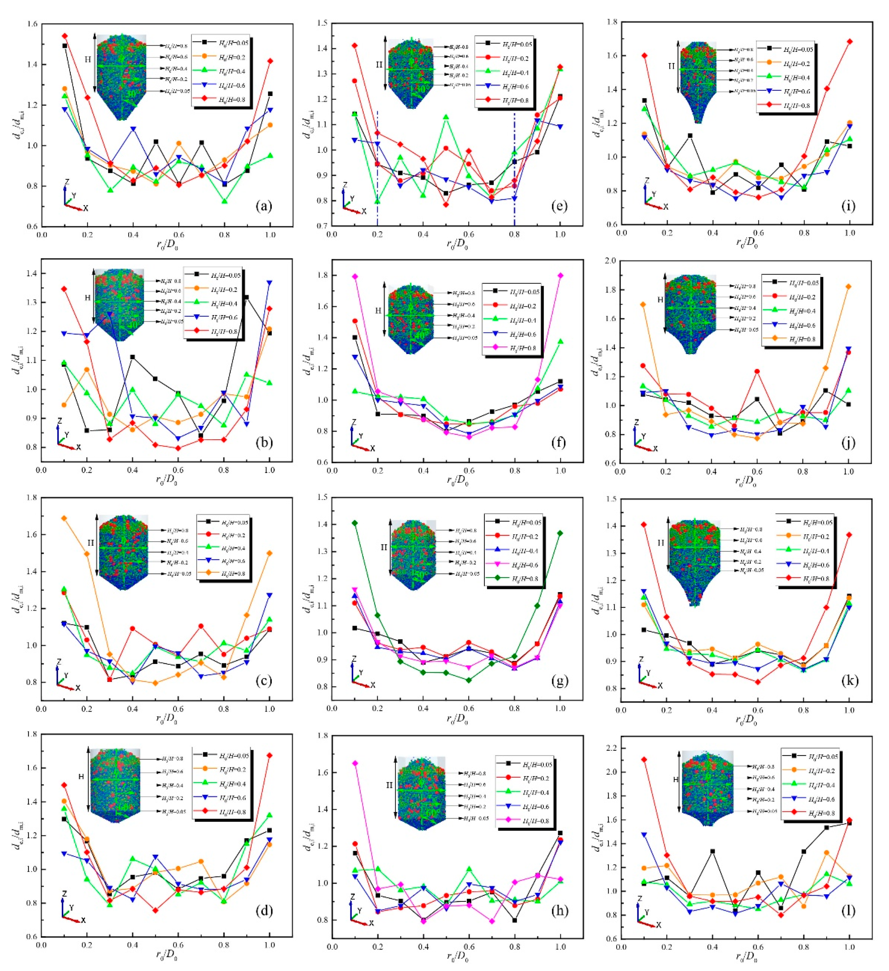
Figure 11 presents the variation in the segregation index for different half hopper angles for the circular and rectangular geometries, and the contraction rate of the hopper varies with an identical half hopper angle in the situation of the previous geometry types (circular and rectangular) as the initial angle for the curved geometry type. To guarantee comparing the effect of the structure of the three geometry types on the variation in the particle segregation index under identical conditions, the cylindrical section is based on the method of identical volume, the hopper shares an identical height in the three geometry types of structures, and the normalized outlet remains the same value. The overall trend of the three geometry types presents two distinct situations: the magnitude of the segregation index gradually increases with a decrease in the dimensionless height of the vertical packed bed near the sidewall, while the corresponding value slightly increases with an increase in the dimensionless height of the vertical packed bed in the central section. It is possible that the flow pattern transition emerges with the decrease in the height of the packed bed, and the larger particles are squeezed near the sidewall, which gives rise to the segregation index, while the finer particles accumulate in the central section of the flow passage, causing the segregation index to decrease. Figure 11a–d shows that the magnitude of the fluctuation of the segregation index deeply decreases as the half hopper angle increases. Perhaps the transformation of the flow pattern is accelerated with an increase in the half hopper angle, and the fluctuation of the segregation index in different layers shares a constant magnitude. Figure 11e–h shows the variation of the segregation index along the height of the sinter layers for the rectangular geometry type. The fluctuation of the segregation index gradually decreases between half hopper angles of 30° and 50°, and the corresponding value slightly increases with the increase in the half hopper angle because of the emergence of a funnel flow pattern with between half hopper angles of 30° and 50° and the effect of the resistance of the hopper on not only the particle layers in the sidewall section but also the particle layers in the central section. Figure 11i–l describes the evolution of the segregation index for the curved geometry type of the VSCB with different contraction rates. The segregation index slightly decreases between a contraction rate equal to 1.94 (Figure 11i), and the corresponding value in Figure 11k is 3.67, which deeply increases with a continuous increase in the contraction rate. Notably, the evolution of the segregation index in the central section slightly fluctuates around the value of the segregation index equal to 1 because the contraction rate remains constant with a decrease in the height of the hopper, leading to a reduced resistance between sinter layers compared with those of the abovementioned geometry types.

4.4.3. The Effect of the External Geometry for Different Geometry Factors on the Segregation Index

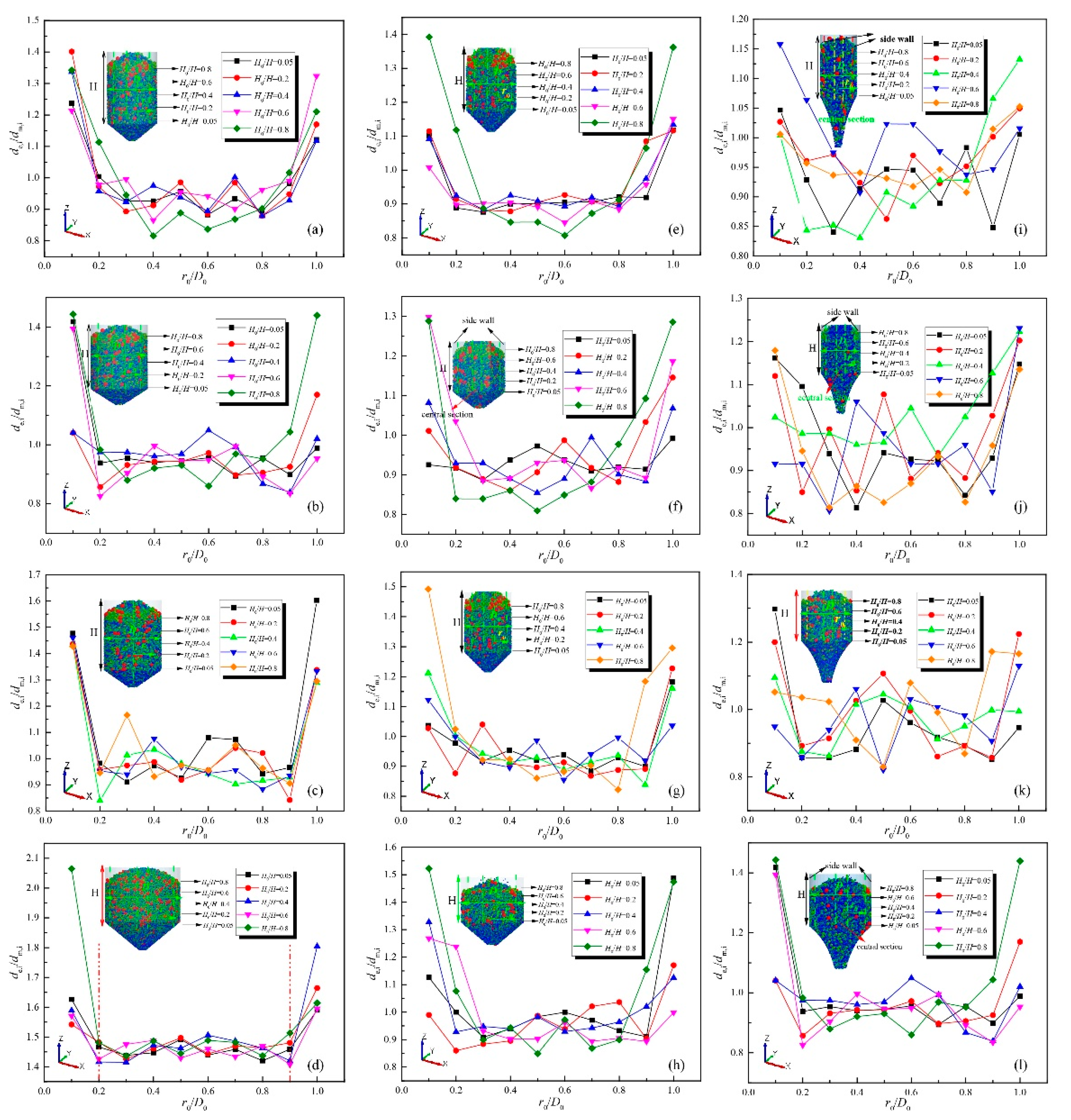
Figure 12 compares the evolution of the segregation index for the three geometry types, namely, circular, rectangular and curved, with different geometry factors. To analyse the segregation index for the three geometry types under identical situations, the hopper height of the curved geometry remains constant between different geometry factors, leading to the curved geometry possessing the same value of the contraction rate. Moreover, the volume of cylindrical sections remains identical among the three geometry types and the same value for the normalized outlet in different geometry types. To guarantee only the effectiveness of the geometric factors on the variation in the segregation index, Figure 12 shows that the fluctuation in the magnitude of the segregation index gradually decreases, while the evolution of the segregation index slightly increases with an increasing geometry factor. Furthermore, the magnitude of the segregation index dramatically decreases from the circular to the curved geometry type, which reveals that the performance of the flow pattern gradually improves as the segregation index fluctuates around a stable value near the initial particle diameter distribution. Figure 12a–d presents the variation in the segregation index for the circular geometry type. The magnitude of the segregation index gradually increases in the central section, and the corresponding value drastically increases near the sidewall with an increase in the geometry factor. Perhaps the accumulation of large particles is accelerated in the sidewall section, and the flow pattern gradually is dominated by a funnel flow pattern with an increase in the geometry factor. Regarding the variation in the segregation index for the rectangular geometry type (Figure 12e–h), the magnitude of the segregation index varies with the geometry factor along the radius direction and possesses a lower value than the corresponding value for the circular geometry type. The oscillation of the magnitude of the segregation index gradually reaches the steady-state, and the corresponding value fluctuates near 0.85 in the central section of the flow passage with an increase in the geometry factor. The influence of segregation is slightly offset by the larger ratio of the diameter of the packed bed and the particle distribution. The results show that the larger group of particles dominates the sidewall section and that the smaller particles play an important role in the central section and vary with the geometric factors, which presents an intensification of segregation that influences the particle distribution process with increasing geometric factors. In regard to the curved geometry type for different geometry factors (Figure 12i–l, the magnitude of the segregation index gradually decreases, and the fluctuation of the corresponding value remains slightly constant with an increase in the geometry factor. The value of the segregation index oscillates near 1 in the upper dimensionless height of the packed bed (0.6–0.8), while the corresponding value fluctuates near 0.95 in the lower dimensionless height of the packed bed (0.05–0.4). The magnitude of segregation decreases slightly because of the emergence of the funnel flow pattern, leading to a quantity of fine particles accumulating in the central flow passage with an increase in the geometry factor.

5. Conclusions

The effect of the three external structures of the VSCB, including the circular, rectangular and curved geometry types, on the characteristics of the sinter particle flow profiles and size segregation with different normalized outlets, half hopper angles and geometry factors, was examined using the DEM.
(1)
The characteristics of the flow profiles and segregation for the three geometry types vary with the normalized outlet: the velocity distribution greatly increases in the central section and gradually decreases in the sidewall section with a normalized outlet increase for the circular and rectangular geometry types, while the corresponding values in the central and sidewall sections sustainably increase with a normalized outlet increase for the curved geometry type. The stabilization of the velocity distribution in the sinter layers gradually decreases, and the height of the mass flow pattern increases as the normalized outlet increases for the circular and rectangular geometry types, while slight fluctuations in the magnitude of MFI varies with the normalized outlet. The optimal performance of the flow pattern is near the normalized outlet of 0.3. Regarding the evolution of the segregation index for the three geometry types with different normalized outlets, the magnitude of the segregation index dramatically decreases in the sidewall section, while the corresponding value in the centre remains stable with a normalized outlet increase for the three geometry types. A comparison of the effectiveness in controlling the segregation index for the three geometry types shows that the curved geometry type has a significant effect on improving the segregation index distribution in sinter layers.
(2)
The characteristics of the flow profiles and segregation for the three geometry types vary with the half hopper angle: the velocity distribution of the sinter layers for the three geometry types with different half hooper angles (the curved geometry with an identical initial angle to that of the circular and rectangular geometries, especially). The variation in the magnitude of the velocity distribution gradually increases prior to remaining constant in the central section for the circular geometry, while the opposite trend is observed for the curved geometry with an increase in the half hopper angle. However, the magnitude of the velocity distribution in the central section dramatically increases with an increase in the half hopper angle for the rectangular geometry. With respect to the evolution of MFI for the three geometry types varying with half hopper angle, the height of the mass flow has a negative correlation with the half hopper angle. With respect to the segregation index varying with half hopper angle for the rectangular geometry, the segregation index slightly fluctuates and gradually increases prior to a drastic decrease, while the corresponding value gradually decreases and remains stable prior to greatly oscillating with an increase in the half hopper angle. In terms of the variation of the segregation index for the curved geometry type, the segregation index gradually decreases in the sidewall, and the corresponding value remains constant in the centre with a half hopper angle.
(3)
The characteristics of the flow profiles and segregation for the three geometry types vary with the geometry factor: the velocity distributions for the three geometry types vary with the different geometry factors. The magnitude of the velocity distribution in the sinter layers drastically increases prior to remaining constant in the central section for the circular geometry type, while the corresponding value for the curved geometry slightly increases prior to remaining stable in the central section with an increase in the geometry factor. The magnitude of the velocity continuously dramatically increases with an increase in the geometry factor. By comparison, the height of the mass flow pattern for the curved geometry is four-fold and three-fold those of the circular and rectangular geometry types, respectively. In terms of the evolution of the segregation index for the three geometry types varying with an increase in the geometry factor, the magnitude of the segregation index slightly fluctuates prior to remaining stable in the central section, and the corresponding value sustainably increases in the sidewall section, while a similar trend in the variation of the segregation index is recorded for the rectangular geometry type. Regarding the variation in the segregation index in sinter layers with an increase in the geometry factor for the curved geometry type, the magnitude of the segregation index oscillates around a value of 1, while the corresponding value slightly increases in the sidewall.

Author Contributions

Conceptualization, J.C. and J.F.; methodology, J.F.; software, J.F.; validation, J.F.; formal analysis, J.F.; investigation, J.F.; resources, J.C.; data curation, J.C.; writing—original draft preparation, J.F.; writing—review and editing, J.F. and J.C.; visualization, J.F. and J.C.; supervision, J.C.; project administration, J.C.; funding acquisition, J.C. Both authors have read and agreed to the published version of the manuscript.

Funding

This research received no external funding.

Acknowledgments

This research is funded by National Key R&D (research and development) Program of China, grant number 2017YFB0304200 and the National Natural Science Foundation of China, grant number 51734004.

Conflicts of Interest

There is no conflict of interest.

Nomenclature

miMass of particle i (kg)
viTranslational velocity of particle i (m∙s−1)
iParticle i
tTime (s)
gGravitational acceleration (m∙s−2)
niNumber of contact particles
FcnNormal contact force (N)
FdnNormal damping force (N)
FctTangential contact force (N)
FdtTangential contact force (N)
IiInertial moment of particle i (kg∙m−2)
ωiAngular velocity of particle i (rad∙s−1)
Tt,ijTangential torque (N·m)
Tr,ijRolling friction torque (N·m)
E*Equivalent young’s modulus (MPa)
r*Equivalent radius (m)
δnOverlap distance of two particles (m)
nijNormal unit vector (-)
υPoisson’s ratio (-)
G*Equivalent shear modulus (MPa)
tijTangential unit vector (-)
eRestitution coefficient (-)
SnNormal elastic constant coefficient (MPa∙m−2)
StTangential elastic constant coefficient (MPa∙m−2)
rijContact radius of two particles (m)
nNormal direction component (-)
tTangential direction component (-)
m*Equivalent mass (kg)
μCoefficient of particles friction (-)
vijtTangential velocity (m∙s−1)
vijnNormal velocity (m∙s−1)
ωt,ijTangential angular velocity of particle i (rad∙s−1)
rError value (%)
fcal,iCalculation results in the ith case (kg·s−1)
fexp,iExperiment results in the ith case (kg·s−1)
vwVelocity of the sidewall (mm·s−1)
vcVelocity of the central section (mm·s−1)
msAverage mass flow rate (kg·s−1)
VUIjVelocity uniformity index in the jth layer
vjkVelocity of the kth column in the jth layer (mm·s−1)
vave,jVelocity of the jth layer (mm·s−1)
vrVelocity of the rth time step in operating time (mm·s−1)
rijShear stress of unit element (MPa)
|r*|Shear rate tensor
ρbBulk density of sinter layers (kg·m3)
D0Dimension of the outlet of VSCB (mm)
GAcceleration of gravity of mass (m·s−2)
nTotal number of experiments
αHalf hopper angles (°)

Abbreviations

DEMDiscrete element method
VSCBVertical sinter cooling packed bed
VUIVelocity uniformity index
MFIMass flow index
FrFroude number

References

  1. Qiu, L.; Li, Y.L.; Feng, Y.H.; Zhang, X.X. Numerical simulation of waste heat recovery for blast furnace slag with multi-particles distribution in moving bed. J. Eng. Thermophys. 2019, 40, 2407–2412. [Google Scholar]
  2. Feng, Y.; Zhang, X.; Yu, Q.; Shi, Z.; Liu, Z.; Zhang, H.; Liu, H. Experimental and numerical investigations of coke descending behavior in a coke dry quenching cooling shaft. Appl. Therm. Eng. 2008, 28, 1485–1490. [Google Scholar] [CrossRef]
  3. Wang, H.; Chu, M.; Bao, J.; Liu, Z.; Tang, J.; Long, H. Experimental study on impact of iron coke hot briquette as an alternative fuel on isothermal reduction of pellets under simulated blast furnace conditions. Fuel 2020, 268, 117339. [Google Scholar] [CrossRef]
  4. Piringer, H. Lime shaft kilns. Energy Proc. 2017, 120, 75–95. [Google Scholar] [CrossRef]
  5. Mellmann, J.; Hoffmann, T.; Furll, C. Mass flow during unloading of agricultural bulk materials from soils depending on particle form, flow properties and geometry of the discharge opening. Powder Technol. 2014, 253, 46–52. [Google Scholar] [CrossRef]
  6. Lareo, C.; Nedderman, R.; Fryer, P.J. Practical velocity profiles for solid-liquid food flows in vertical pipes part Ⅱ. Multiple particles. Powder Technol. 1997, 93, 35–45. [Google Scholar] [CrossRef]
  7. Merwe, W.J.; Toit, C.G.; Kruger, J.H. Influent of the packing structure on the flow through packed beds with small cylindrical diameter to particle diameter ratios. Nucl. Eng. Des. 2020, 365, 110700. [Google Scholar] [CrossRef]
  8. Qian, P.; Wang, J.-Y.; Wu, Z.-H.; Yang, J.; Wang, Q.-W. Performance comparison of methane steam reforming in a randomly packed bed and a grille-sphere composite packed bed. Energy Convers. Manag. 2019, 193, 39–51. [Google Scholar] [CrossRef]
  9. Babout, L.; Grudzien, K.; Waktola, S.; Miskiewicz, K.; Adrien, J.; Maire, E. Quantitative analysis of flow dynamics of organic granular materials inside a versatile silo model during time-lapse X-ray tomography experiments. Comput. Electron. Agric. 2020, 172, 105346. [Google Scholar] [CrossRef]
  10. Zaki, M.; Siraj, M.-S. Study of a flat-bottomed cylindrical silo with different orifice shapes. Powder Technol. 2019, 354, 641–652. [Google Scholar] [CrossRef]
  11. Zhang, C.; Gao, J.; Zeng, L.; Xia, Y.; Xie, W.; Ye, W. Experimental analysis of the resistance of packed beds based on the morphology of cylindrical. Powder Technol. 2020, 369, 238–247. [Google Scholar] [CrossRef]
  12. Liu, H.; Jia, F.-G.; Xiao, Y.-W.; Han, Y.-L.; Li, G.-G. Numerical analysis of the effect of the contraction rate of the curved hopper on flow characteristics of the silo discharge. Powder Technol. 2019, 356, 858–870. [Google Scholar] [CrossRef]
  13. Yang, X.; Jian, X.; Zhe, H.L. DEM study on ternary-size particle segregation during the sinter burden charging process. Powder Technol. 2019, 343, 422–435. [Google Scholar]
  14. Huang, A.N.; Cheng, T.H.; Hsu, W.Y. DEM study of particle segregation in a rotating drum with internal diameter variations. Powder Technol. 2020, 378, 430–440. [Google Scholar]
  15. Yang, J.C.; Guo, Y.; Buettner, K.E. DEM investigation of shear flows of binary mixtures of non-spherical particles. Powder Technol. 2019, 202, 383–391. [Google Scholar] [CrossRef]
  16. Govender, N.; Daniel, N.W.; Wu, C.Y. Hopper flow of irregularly shaped particles (non-convex polyhedral): GPU-based DEM simulation and experimental validation. Chem. Eng. Sci. 2018, 188, 34–51. [Google Scholar] [CrossRef] [Green Version]
  17. Ma, H.Q.; Zhao, Y.Z. Modelling of the flow of ellipsoidal particles in a horizontal rotating drum based on DEM simulation. Chem. Eng. Sci. 2017, 172, 636–651. [Google Scholar] [CrossRef]
  18. Qiu, J.Y.; Ju, D.C.; Zhang, J.L.; Xu, Y.S. DEM simulation of particle flow in a parallel-hopper bell-less charging apparatus for blast furnace. Powder Technol. 2017, 314, 218–231. [Google Scholar] [CrossRef]
  19. Cundall, P.; Strack, O. Modeling of Microscopic Mechanisms in Granular Material. Stud. Appl. Mech. 1983, 7, 137–149. [Google Scholar] [CrossRef]
  20. Aleshin, V.V.; Abeele, K.V.D. Preisach analysis of the Hertz–Mindlin system. J. Mech. Phys. Solids 2009, 57, 657–672. [Google Scholar] [CrossRef]
  21. Aleshin, V.; Abeele, K.V.D. General solution to the Hertz–Mindlin problem via Preisach formalism. Int. J. Non-Linear Mech. 2013, 49, 15–30. [Google Scholar] [CrossRef]
  22. Zhang, Y.; Jia, F.; Zeng, Y.; Han, Y.; Xiao, Y. DEM study in the critical height of flow mechanism transition in a conical silo. Powder Technol. 2018, 331, 98–106. [Google Scholar] [CrossRef]
  23. Zeng, Y.; Jia, F.; Zhang, Y.; Meng, X.; Han, Y.; Wang, H. DEM study to determine the relationship between particle velocity fluctuations and contact force disappearance. Powder Technol. 2017, 313, 112–121. [Google Scholar] [CrossRef]
  24. Zhao, Y.; Yang, S.-L.; Zhang, L.-Q.; Chem, J.-W. Understanding the vary discharge rates of lognormal particle size distribution from a hopper using the discrete element method. Powder Technol. 2019, 342, 356–370. [Google Scholar] [CrossRef]
  25. Wei, H.; Nie, H.; Li, Y.; Saxen, H.; He, Z.J.; Yu, Y.W. Measurement and simulation validation of DEM parameters of pellet, sinter and coke particles. Powder Technol. 2020, 593–603. [Google Scholar] [CrossRef]
  26. Lehmann, H.J. Ein beitrag zur untersuchung des einflusses der schuttguteigenchaften und der bwhaltergeometrie auf massendurchdatz beim ausflieben von Schuttgut aus zylindrischen behaltern. Ph.D. Dissertation, Hochschule für Technik, Wirtschaft und Kultur Leipzig, Weimar, Germany, 1978. [Google Scholar]
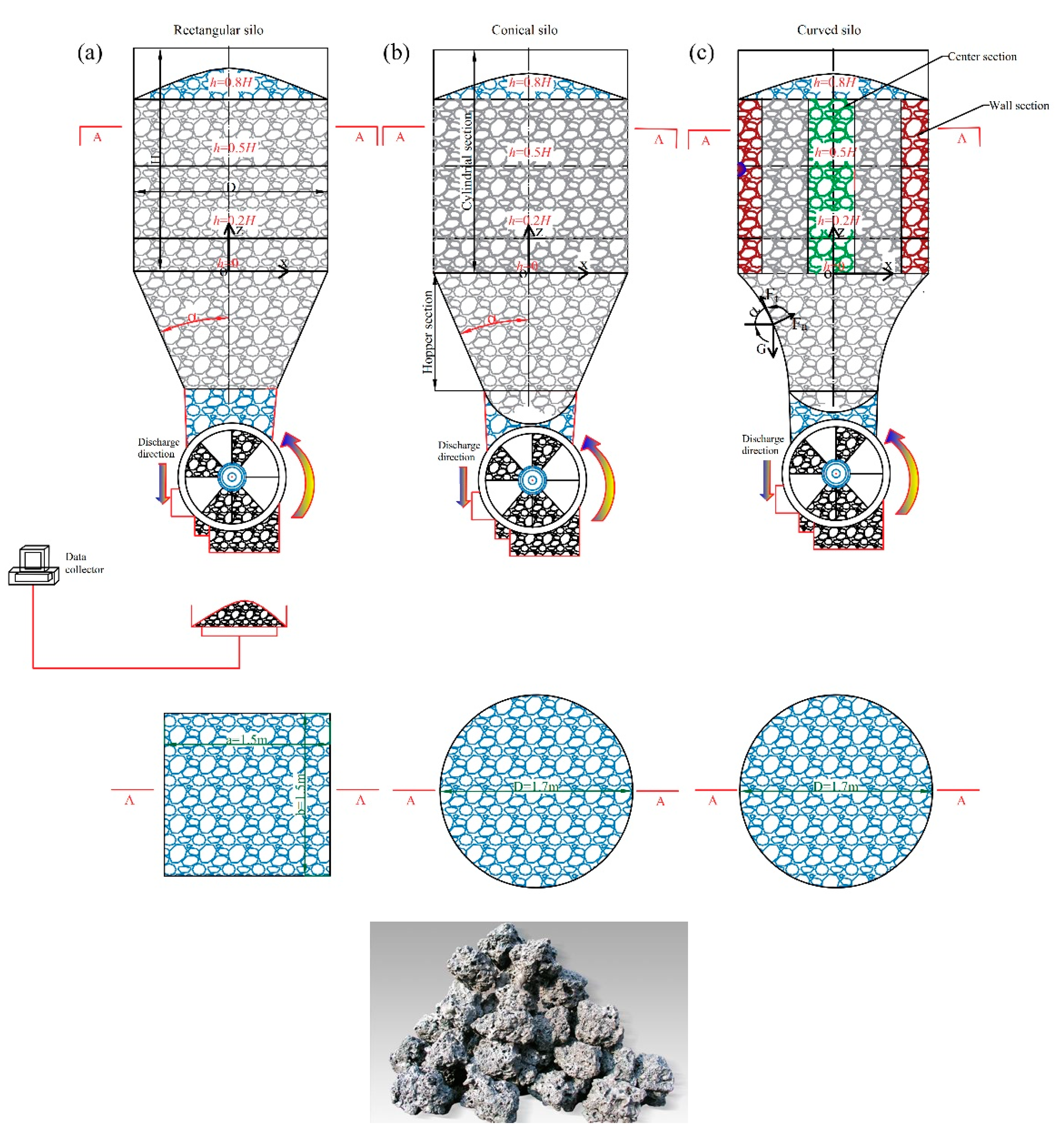
Figure 1. Schematic diagram of the structures of the three geometry types of the VSCB and sinter particles’ external figure. (a) rectangular (b) circular (c) curved.
Energies 13 05964 g001
Figure 2. The validation of mass flow rate for three types geometry between tested value and calculated value (a,b) curved geometry (c,d) rectangular geometry (e,f) circular geometry.
Energies 13 05964 g002
Figure 3. Validation of the variation in the Froude number for the three geometry types: (a) circular geometry with different half hopper angles, (b) rectangular geometry with different half hopper angles, and (c) curved geometry with different contraction rates sharing an identical half hopper angle (in the range of 30°–60°, with an increase of 10°) in the circular and rectangular geometries.
Energies 13 05964 g003
Figure 4. The variation in the velocity distribution for the three types of VSCB with different normalized outlets: (ac) circular (normalized outlet with 0.2–0.4), (df) rectangular (0.2–0.4) and (hj) curved (0.2–0.4).
Energies 13 05964 g004
Figure 5. The variation in the MFI for the three geometry types of the VSCB with different normalized outlets: (a) circular, (b) rectangular and (c) curved.
Energies 13 05964 g005
Figure 6. Evolution of the velocity for the three geometry types of the VSCB with different half hopper angles: (ad) circular (30°–60°), (eh) rectangular (30°–60°), (il) and curved (initial angle for calculation of contraction rate in the range of 30°–60°, with a step size of 10°).
Energies 13 05964 g006
Figure 7. The evolution of the MFI (mass flow index) for the three geometry types with different half hopper angles: (a) circular (30°–60°), (b) rectangular (30°–60°), and (c) curved (initial angle for calculation of the contraction rate in the range of 30°–60°, with a step size of 10°).
Energies 13 05964 g007
Figure 8. The variation in the velocity distribution along the height of the packed bed for the three geometry types of the VSCB with different geometry factors: (ad) circular (for geometry factors of 75–150), (eh) rectangular (for geometry factors of 75–150), and (il) curved (for geometry factors of 75–150).
Energies 13 05964 g008
Figure 9. Variation in the MFI (mass flow index) for the three geometry types with different geometry factors: (a) circular, (b) rectangular and (c) curved.
Energies 13 05964 g009
Figure 10. Variation in the segregation index (de,i/dm,i) for the three geometry types of the VSCB with different normalized outlets: (ac) circular type (0.2–0.4), (df) rectangular type (0.2–0.4) and (gi) curved type (0.2–0.4).
Energies 13 05964 g010
Figure 11. Variation in the segregation index for the three geometry types of VSCBs with different half hopper angles: (ad) circular (30°–60°), (eh) rectangular (30°–60°), and (il) curved (initial angle for calculation of the contraction rate in the range of 30°–60°, with a step size of 10°).
Energies 13 05964 g011
Figure 12. Variation in the segregation index for the three geometry types of the VSCB with different geometry factors: (ad) circular (with geometry factors of 75–150), (eh) rectangular (with geometry factors of 75–150), and (il) curved (with geometry factors of 75–150).
Energies 13 05964 g012
Table 1. The force and torque parameters calculated for contact between particles i and j.
ParametersSymbolsEquations
Normal contact forceFcn F c n = 4 3 E ( r ) 1 / 2 δ n 3 / 2 n i j
Tangential contact forceFct F c t = 8 G r δ n t i j t < δt,max)
Normal damping forceFdn F d n = 2 5 6 ln e ln 2 e + π 2 S n m v i j n
Tangential damping forceFdt F d t = 2 5 6 ln e ln 2 e + π 2 S t m v i j t t < δt,max)
Torque by tangential forcesTt,ij T t , i j = r i j × ( F c t + F d t )
Rolling friction torqueTr,ij T r , i j = μ r , i j ( F c , i j n + F d , i j n ) ω t , i j / | ω t , i j |
Table 2. Parameters used in the DEM calculation.
ParametersValueUnits
Particles static friction0.3-
Particles rolling fraction0.1-
Restitution between particles0.15-
Young’s modulus2.6 × 109Pa
Poisson’s ratio0.25-
Wall static frictional coefficient0.2-
Wall rolling frictional coefficient0.15-
Restitution between particles and wall0.2-
Young’s modulus of wall7 × 1010Mpa
Poisson’s ratio of wall0.3-
Bulk density of sinter particles2800kg·m−3
Publisher’s Note: MDPI stays neutral with regard to jurisdictional claims in published maps and institutional affiliations.