Abstract
Layers of titania are the critical components in sensitized photovoltaics. The transfer of electrons occurs from the dye molecule to the external circuit through a transparent conducting oxide, namely fluorine-doped tin oxide (FTO). Porosity, interparticle connectivity, and the titania films’ defects play a vital role in assessing the dye-sensitized solar cells’ (DSSCs) performance. The conventional methods typically take several hours to fabricate these layers. This is a significant impediment for the large-scale manufacture of DSSCs. This step can be reduced to a few hours by a microwave sintering process and may facilitate the rapid fabrication of the critical layers for sensitized photovoltaics, thus, boosting the prospects for the commercialization of these devices. In the present study, we aimed to perform different heat treatments (conventional and microwave) on the titania films with different temperatures to understand the phase formation, transmittance, and porosity without losing the titania’s interparticle connectivity. The solar cell performance of microwave-sintered titania films is comparatively higher than that of conventionally sintered titania films.
1. Introduction
In 1991, Gratzel first reported the 11% efficiency of dye-sensitized solar cells assembled with Ru complex-based sensitizer at the EPFL (École Polytechnique Federale de Lausanne) [1]. When porphyrin-based sensitizers are used, the maximum efficiency of DSSC achieved is 13% [2]. Typical DSSCs consist of three parts, namely, a photoanode comprising nanocrystalline titanium dioxide fabricated on a transparent conducting oxide (FTO) substrate with dye molecules adsorbed on a mesoporous titania (TiO2) surface, a platinum counter electrode, and an electrolyte solution containing redox couple with iodide ion/tri-iodide ions between the electrodes. In DSSCs, dye molecules that are adsorbed onto the exterior of the TiO2 are responsible for the light harvesting. When the dye molecule captures the incident photons, it generates excitons, which split at the nanocrystallite TiO2 surface. Further, when electrons are injected into the TiO2 film, holes pass towards the liquid electrolyte solution containing redox couple [3,4,5,6,7,8]. Electrons are transported into the mesoporous titania film by diffusion and get trapped in the sites that are already present [9]. As the electrons’ injection into the conduction band of titania is faster than the electrons’ diffusion in the mesoporous titania film, which is a slower process (milliseconds), this employs a critical role in determining the current generated by a DSSC [10].
A good quality photoanode is necessary to achieve high efficiency for DSSCs. Factors such as phase composition, porosity, thickness, crystallinity, and interparticle connectivity of titania film over FTO are crucial for effective dye adsorption and the effective diffusion of electrons through the film. But it is somewhat difficult to prepare a photoanode with good porosity and a proper interparticle connection of the film’s titania particles. When the titania film’s heat treatment is taking place, an interparticle neck is formed, which establishes connectivity between titania particles. Most of the research community is concentrated on the conventional sintering procedure to obtain titania’s porous films. The traditional sintering procedures result in a poor interconnection between the titania particles in the photoanode and non-uniformity in the porosity, which may vary from one device to another [11,12,13,14,15,16].
A microwave sintering procedure is adopted to achieve the titania particles’ uniform porosity with good interconnectivity in the photoanode and high consistency among all the substrates. In the present investigation, we determined that the microwave sintering process is more advantageous than conventional sintering for titania films in attaining uniform porosity, good interconnectivity, and effective dye adsorption, which enabled us to prepare a DSSC with a low mean deviation of already- obtained efficiency.
2. Experimental Details
2.1. Materials
The chemicals, such as polyethelene glycol (PEG 600), ethanol, and triton X-100 are of Merck AR grade. TiO2 powder (P 25, Degussa), LiI (99.9%), I2 (99.99%), acetonitrile (99.8%), LiClO4 (99.99%), 4-tert-butylpyridine (4-tbp, 96%), and 1-methyl-3-propylimidazolium iodide (98%) were purchased from Sigma-Aldrich. A conductive transparent electrode, Surlyn spacer, dye (N3), and fluorine-doped tin oxide (FTO) on glass (sheet resistance ~8 Ω cm−2) were obtained from Dyesol, Australia. The redox electrolyte solution for the DSSC application was prepared by using 0.5 M 4-tbp, 0.05 M I2, 0.6 M 1-methyl-3-propylimidazolium iodide, and 0.5 M LiI in acetonitrile.
2.2. Mesoporous Titania Films (Photoanode)
To prepare a photoanode, we initially needed to prepare the TiO2 slurry. The details of the preparation of the TiO2 slurry can be found elsewhere [17]. In brief, TiO2 powder (Degussa P25) was mixed with PEG 600 and ethanol in appropriate amounts in a polypropylene bottle having grinding media. The mixer was kept on the pot mill for 48 h to get a homogeneous TiO2 slurry. The prepared slurry was coated on the pre-cleaned transparent conducting oxide (TCO) substrate (FTO in our case) using the doctor blade technique. After coating, the substrates were dried under air for 1 h and sintered in two different heat treatments. One was a conventional heat treatment, meaning the films were sintered using a muffle furnace, and the second was microwave heat treatment, meaning the films were sintered using a microwave furnace. The films were sintered at various temperatures to better understand the interconnecting particle mechanism of titania films. The sintering temperatures were kept at 350 °C, 400 °C, and 450 °C in each case of the heat treatments, and the samples were referred to as C350, C400, and C450, respectively, in the case of conventional sintering. In contrast, the samples were referred to as M350, M400, and M450, respectively, for the microwave sintering. These sintered films have an active area of 0.25 cm2, with thickness of approximately 4–5 micron. The TiO2 films were immersed in the prepared dye (N3 of 0.3 mM in ethanol) solution for 24 h under room temperature and dark conditions to obtain sensitized films, and later named “photoanode”. The electrolyte consisted of 0.5 M 4-tbp, 0.5 M LiI, 0.5 M 1-butyl-3-methylimidazolium iodide (ionic liquid) and 0.05 M I2 in acetonitrile solution.
2.3. Counter Electrode Preparation
The Pt counter electrode was prepared by Radio frequency (RF) sputtering (Nordiko, TFR16272; Power: 150 W; working pressure: 2.3 × 10⁻³ mbar of Ar gas, Hampshire PO9 5TL, UK) at room temperature on FTO substrates, and the thickness was found to be 30 nm.
2.4. DSSC Fabrication
The DSSC device was fabricated by sandwiching the photoanode and the counter electrodes by placing a spacer (Soloronix 25 µm, Aubonne, Switzerland) in between them. A drop of redox electrolyte iodide/triiodide (I−/I3−) was slowly injected into the electrodes’ gap without any air bubbles. The electrolyte consisted of 0.5 M LiI, 0.05 M I2, 0.5 M 4-tbp, and 0.5 M 1-butyl-3-methylimidazolium iodide (ionic liquid) in acetonitrile solution. The final device was used for the parent characterization in order to investigate the photovoltaic performance.
2.5. Physical Characterizations
Crystallinity and the phase distribution of sintered films were analyzed by an X-ray diffractometer (PANalytical X-ray diffractometer) with Cu Kα source at 1.54 Å. The thickness of the prepared films was measured. The microstructure and the elemental analysis of the sintered films were investigated using field emission scanning electron microscopy (FEGSEM) of JEOL, JSM 7600F with energy dispersive X-Ray (EDX), and high-resolution transmission electron microscopy (HR-TEM) of model JEOL, JEM 2100F. The transmission, dye adsorption, and desorption studies of the films were made using the UV−Vis spectrophotometer of Jasco, V-650 model, comprising an integrating sphere. The current density and voltage (J−V) measurements were elucidated by the solar simulator, containing a xenon arc lamp (150 W) and were capable of one sun (AM 1.5, 100 mW cm−2) output. The voltage sweep during the J−V measurements was monitored by a Keithley 2420 source meter.
3. Results and Discussion
3.1. Crystal Structure and Domain Analysis
The X-rays diffraction (XRD) patterns of sintered titania films are shown in Figure 1. There is an intense peak noted at 2θ = 25.3° for (101) plane (JCPDS 21-1272) pertaining to anatase phase, and a small peak was recorded at 2θ = 27.5 ° for (110) plane (JCPDS 21-1276), related to rutile phase in all samples [18]. Figure 1a,b show the XRD patterns of conventionally and microwave sintered films, respectively. The average crystallite size (D) was evaluated from Scherrer’s expression, and the percentage of anatase phase (f) was calculated using the formula given below.
where β is the full width at half maximum (FWHM) of the corresponding XRD peak at radiant. K = 0.89 is the correction factor, which is correlated to the shape of nanoparticles, λ is X-ray wavelength (kα = 0.15406 nm), and θ is the Bragg diffraction angle [19,20,21].
where IR is the intensity of the rutile peak of (110) and IA is the intensity of the anatase peak of (101).
D = Kλ/βCosθ
ƒ = [1 + 1.26(IR/IA)]−1
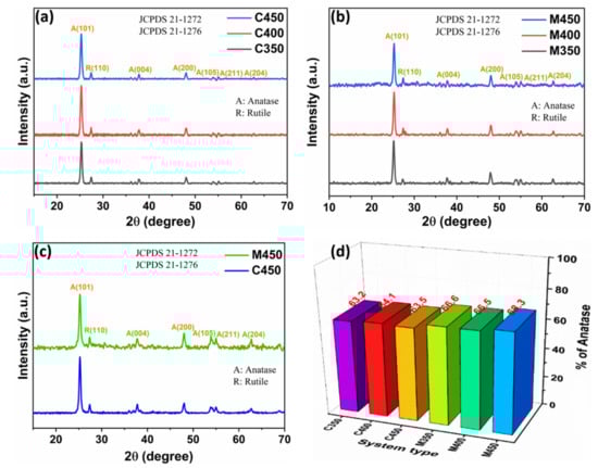
Figure 1.
XRD patterns of (a) Conventional, (b) Microwave sintered titania films, (c) Conventional and microwave sintered films at 450 °C, and (d) Percentage of anatase phase.
The DSSC is fabricated with a mesoporous titania film that is sintered at 450 °C for better performance. To understand this, XRD patterns of conventionally and microwave sintered titania films at 450 °C are separately plotted, as shown in Figure 1c. All samples’ detailed anatase phase distributions and contributions were calculated using the above equations and plotted in Figure 1d. The sample M450 has the highest value of the anatase phase of approximately 68.3%, influencing the device’s performance. The corresponding XRD parameters are tabulated in Table 1.

Table 1.
XRD parameters of the titania films
3.2. Transmittance Studies
It is necessary to analyze the transmittance behavior of the films with and without dye loading to better understand the influence of film quality on the cells’ performance. Figure 2 shows that the various titania films’ transmittance spectra through microwave and conventional sintering processes with and without dye loading are noted. Figure 2a indicates the transmittance spectra of conventionally sintered films at different temperatures; bare FTO transmittance data was also included for reference. Primarily, it is observed that there is not much change in the transmittance for the C350, C400, and C450 samples. Figure 2b shows the transmittance spectra of the corresponding Figure 2a with dye loading. Figure 2c shows the transmittance spectra of microwave sintered films at different temperatures, with bare FTO reference. It is observed that there is a minute change in the transmittance for the M450 as compared to the M400 and M350 samples. Figure 2d indicates the corresponding Figure 2c transmittance spectra with dye loading. An exact understanding of samples C450 and M450 with and without dye adsorption is plotted separately and shown in Figure 2e. It is clearly understood that the transmittance of both C450 and M450 is the same without dye loading. However, there is a considerable change in the transmittance of C450 and M450 with dye loading, which is a crucial factor for more incident light to be able to pass through the film; thus, more electrons can be generated. This transmittance change may be due to the higher anatase phase existence in the M450 sample as compared to C450.
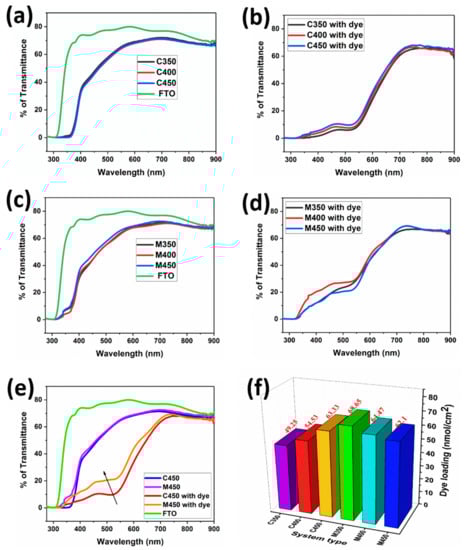
Figure 2.
Transmittance spectra of (a,c) Conventionally and microwave sintered titania films without dye, (b,d) Conventionally and microwave sintered titania films with dye, (e) Transmittance spectra of conventional and microwave sintered films at 450 °C with and without dye, and (f) Dye-loading profile of various samples.
3.3. Dye Adsorb–Desorb Studies
The loading of the dye (light-absorbing material) into the TiO2 porous structure is one of the critical parameters in DSSC performance. The conventional and microwave sintered samples that are discussed above are subjected to the dye loading by dipping into the N3 dye solution (0.3 mmol in ethanol) and left soaking for 24 h. During the soaking process, the organic N3 dye is adsorbed onto the porous TiO2 structures by filling pores. The amount of loaded dye is quantified by conducting dye-desorbing studies. These studies were carried out for both conventional and microwave sintered samples by dipping them in 5 mL of 1N NaOH solution in water. The desorbed dye dissolved in 5 mL NaOH solution was subjected to UV-Vis spectrophotometer studies at a particular wavelength of 500 nm by taking 1 mL of dye solution in the cuvette for concentration evolution [11]. Evaluated concentrations are tabulated below and plotted, as shown in Figure 2f. The conventional sintered samples C350, C400, and C450, have concentrations of 49.25, 54.53, and 63.33 nmol cm−2, respectively. C450 has a comparatively higher dye-loading capacity than the other two conventional sintering samples due to high porosity, making them adsorb more due to the high volume of surface area. The microwave sintered samples M350 and M400 have even higher dye content than C450 due to the even higher porosity described in the subsequent section with the help of FEGSEM images. The M450 sample has comparatively low dye-loading capacity, which is expected due to the better interconnectivity of the sintered TiO2, which makes less porosity available to dye to adsorb on. The effective electron transfer counterbalances the effect of sacrificed loaded-dye content due to the better interconnectivity of TiO2 in M450, which is shown in the form of device performance discussed in the subsequent section.
3.4. Thickness Measurement
Thickness measurements for the prepared titania films with various sintering profiles in both methods (conventional and microwave) were carried out using a stylus-based profilometer and tabulated below. It is observed that the thickness of all the samples is the same, approximately 5 µm. These thickness profiles were also confirmed from the scanning electron microscopy image (SEM) cross-section analysis in Figure 3. The thickness and the corresponding dye loading of the prepared films are tabulated in Table 2.
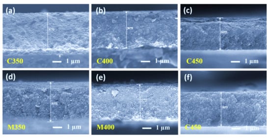
Figure 3.
Scanning electron microscopy cross-sectional images of (a–c) Conventionally sintered titania films, and (d–f) Microwave sintered titania films.
Table 2.
The thickness and dye loading of the prepared films
3.5. High-Resolution Surface, Cross-Section, and Fractography Analysis
The FEGSEM images for all the samples are shown below in Figure 3, Figure 4 and Figure 5. On observation, it is understood that microwave sintered samples have shown higher porosity and better film quality than the conventionally sintered samples. In the conventional sintering process, samples are subjected to high temperatures to create porosity by burning out the organics. If the thickness is high, samples should be exposed for more time to remove the organics from the bottom layers. Therefore, conventional sintering leads to more densification instead of providing porosity if the thickness is high. This is precisely observed in the cross-section images of conventional sintered samples Figure 3a–c.
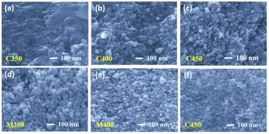
Figure 4.
High-resolution fractography images of (a–c) Conventionally sintered titania films and (d–f) Microwave sintered titania films.
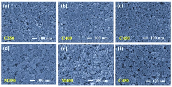
Figure 5.
Scanning electron microscopy surface (top) view images of (a–c) Conventionally sintered titania films and (d–f) Microwave sintered titania films.
Several titania-coated films were prepared on the FTO substrate to evaluate the optimum sintering conditions to obtain the desired porous titania layers, and were subjected to conventional and microwave sintering for 30 min. All the resultant sintered titania films had a thickness of approximately 5 µm. Figure 3 shows the cross-sectional images of both the conventional and microwave sintered samples. On meticulous observation of these microstructures, it is understood that Figure 3a–c are densely packed, which is from conventional sintering at 350 °C, 400 °C, and 450 °C. Figure 3d–f are more porous in nature, which resulted from microwave sintering. The expected reason for more densely packed titania in conventional sintering is that there is no local heating of the films and the temperature rise is not instantaneous due to the limited heating rate. In contrast, microwave sintering material can be locally heated due to the exposed material (TiO2 in this case), and the temperature rises to high values due to the high-power input. This rapid temperature rise can effectively burn off the films’ organics, leaving high volumes of porosity.
Fractography high-resolution images are presented in Figure 4. Careful observation leads us to conclude that the conventional sintered samples at 350 °C and 400 °C were still left with some organics present (Figure 4a,b respectively), and the sample sintered at 450 °C has only sintered TiO2 with dense packing (Figure 4c). The fractography images for the microwave sintered samples at the same temperatures as that of the conventional, at 350 °C and 400 °C, show the organic materials are entirely burnt out, leaving high porosity but low connectivity (Figure 4d,e). At 450 °C, microwave sintering the titania films has a little less porosity than M350 and M400, but better interconnectivity among TiO2 nanoparticles due to proper densification (Figure 4f). All microwave sintered samples at 350 °C, 400 °C, and 450 °C have better porosity than their counterparts in conventional sintering. These observations are also supported by the top view of the FEGSEM images presented in Figure 5a–f. This is because microwave sintering provides an instant heating effect locally in the samples, irrespective of materials thickness; microwaves can penetrate easily and produce a local heating effect. Thus, organics present in the coated film burn out faster, within minutes, and obtain uniform films with high porosity.
3.6. Internal Microstructure and Elemental Analysis
Titania films were subjected to transmission electron microscopy analysis (TEM) to verify the influence of different heating processes on the interparticle connectivity of titania, which leads to the appropriate porosity and its impact on the performance of DSSCs. For this purpose, the sintered titania films were separated gently from the FTO substrates, sonicated in ethanol for 10 min, and given for the TEM analysis. Figure 6 indicates the TEM images of the samples C450 and M450 with selected area electron diffraction (SAED) patterns inset. It is well-observed from Figure 6 that the titania nanoparticles were well connected in the C450 and M450 cases. However, in the case of the conventionally sintered sample (C450), the particles were densely packed, leading to lost porosity.
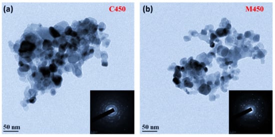
Figure 6.
Transmission electron microscopy images of (a) Conventionally sintered titania, (b) Microwave sintered titania and their corresponding SAED patterns are in the inset.
In contrast, microwave sintered samples (M450) were loosely packed without losing interparticle connectivity, leading to good porosity. This is because microwave sintering provides a fast heating effect locally in the samples, as described in the previous section. The SAED patterns of both samples show the samples’ polycrystalline nature; this is a good agreement with the XRD results. To confirm the samples’ present elements, an energy-dispersive X-ray spectroscopy (EDS) study was carried out, and the corresponding spectra, as shown in Figure 7. It is clear from the figure that both samples (C450 and M450) have pure titania and oxygen alone. No other element traces were found, which indicates the complete burning of the organics present in the titania slurry during the heat treatment process. However, there is a small change in the titania percentage in the microwave sintered sample (M450), which may be due to the high anatase phase existence of titania and is a good agreement with the XRD data.
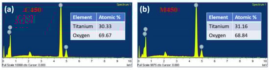
Figure 7.
Energy-dispersive X-ray spectroscopy (EDS) of (a) Conventionally sintered titania, (b) Microwave sintered titania and their corresponding elemental atomic percentage is in the inset table.
3.7. DSSC Device Performance
To understand the effect of microwave sintering in terms of device performance, the conventional and microwave sintered samples, as discussed above, are used for the photoanode preparation and respective fabricated DSSCs. To check these devices’ performance, J-V (current density vs. voltage) measurements were obtained with a solar simulator’s help. The recorded J-V curves for C350, C400, C450, M350, M400, and M450 are shown below in Figure 8a–e. Three cells are fabricated for each batch to check the repeatability, and the corresponding J-V curves are plotted in Figure 8. The observed cell parameters are expressed in Table 3. Figure 9a shows the J-V curves of the champion cells of the conventionally sintered titania-based DSSCs.
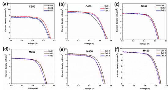
Figure 8.
J-V curves of (a–c) Conventionally sintered titania-based DSSCs, (d–f) Microwave sintered titania-based DSSCs.
Table 3.
J-V parameters of the DSSC
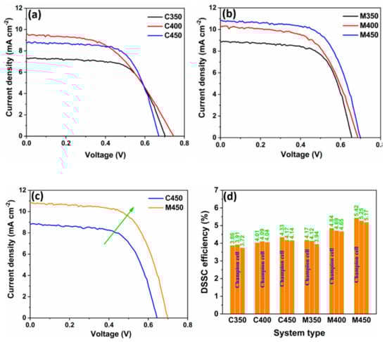
Figure 9.
J-V curves of (a) Conventionally sintered titania-based DSSCs, (b) Microwave sintered titania-based DSSCs, (c) Comparison of J-V characteristics of DSSCs fabricated by conventional and microwave sintering of titania, (d) Graphical representation of the overall devices.
Similarly, Figure 9b shows the J-V curves of the champion cells of the microwave sintered titania-based DSSCs. The performance comparison for the conventional and microwave sintered titania-based DSSC is shown in Figure 9c. In contrast, it is observed that the DSSCs fabricated through the microwave-based photoanode show higher current densities than their respective counterparts, the DSSCs with conventional sintered titania films. The probable reason is the uniform interconnected porosity, which provides effective charge transport without hindrance. In some cases, a low open-circuit voltage was found due to the dye’s direct contact with the FTO due to the titania porosity on the FTO. The maximum photo-conversion efficiency (PCE) of C450-based DSSC is 4.33%, and MW DSSC is 5.42%, which is reasonably higher (a 20% improvement) to emphasize the microwave sintering of TiO2 for the fabrication of better-performing DSSC. A graphical representation of the overall devices is shown in Figure 9d for better understanding.
4. Conclusions
In summary, microwave sintered titania films showed better anatase phase and good transmittance observed from XRD and UV analysis. Better interparticle connectivity of the titania and porosity was observed in microwave sintered films compared to conventionally sintered films and confirmed by SEM analysis. DSSCs fabricated with microwave sintered films as a photoanode showed better performance than the DSSCs fabricated with conventionally sintered samples. The photoconversion efficiency of microwave sintered titania-based DSSC was 5.42% with a current density of 10.09 mA cm−2, which is higher than the conventionally sintered titania-based DSSC of efficiency 4.33% with a current density of 8.77 mA cm−2. These higher values could be ascribed to better interconnectivity of TiO2 particles with good porosity.
Author Contributions
Conceptualization, methodology, sample preparation, writing-original draft, data curation, formal analysis, S.S.N.; investigation, S.R.; formal analysis, investigation, visualization, S.M.; review and editing, validation, P.B.; review and editing, validation; S.B., conceptualization, validation; M.B., validation; A.K.T., validation; D.M., methodology, data curation, formal analysis, writing, review and editing, supervision, project administration. All authors have read and agreed to the published version of the manuscript.
Funding
Siva Sankar Nemala acknowledges the financial support received from the Department of Science and Technology-Science and Engineering Board (DST-SERB) National Post-Doctoral Fellowship by the Government of India (PDF/2019/001151), SAIF IIT Bombay for Characterization facilities, and CEN IIT Bombay for Pt sputtering. Debananda Mohapatra is grateful for the financial support received from the National Research Foundation of Korea (NRF) grant funded by the Korean government (Ministry of Science and ICT) (NRF-2020R1G1A1015243).
Conflicts of Interest
The authors declare no conflict of interest.
References
- O’Regan, B.; Grätzel, M.; Gr, M. A low-cost, high-efficiency solar cell based on dye-sensitized colloidal TiO2 films. Nature 1991, 353, 737–740. [Google Scholar] [CrossRef]
- Mathew, S.; Yella, A.; Gao, P.; Humphry-Baker, R.; Curchod, B.F.E.; Astani, N.A.; Tavernelli, I.; Rothlisberger, U.; Nazeeruddin, K.; Grätzel, M. Dye-sensitized solar cells with 13% efficiency achieved through the molecular engineering of porphyrin sensitizers. Nat. Chem. 2014, 6, 242–247. [Google Scholar] [CrossRef] [PubMed]
- Grätzel, M. Solar Energy Conversion by Dye-Sensitized Photovoltaic Cells. Inorg. Chem. 2005, 44, 6841–6851. [Google Scholar] [CrossRef] [PubMed]
- Grätzel, M. Dye-sensitized solar cells. J. Photochem. Photobiol. C: Photochem. Rev. 2003, 4, 145–153. [Google Scholar] [CrossRef]
- Nemala, S.S.; Kartikay, P.; Prathapani, S.; Bohm, H.L.M.; Bhargava, P.; Bohm, S.; Mallick, S. Liquid phase high shear exfoliated graphene nanoplatelets as counter electrode material for dye-sensitized solar cells. J. Colloid Interface Sci. 2017, 499, 9–16. [Google Scholar] [CrossRef]
- Saranya, K.; Sivasankar, N.; Subramania, A. Microwave-assisted exfoliation method to develop platinum-decorated graphene nanosheets as a low cost counter electrode for dye-sensitized solar cells. RSC Adv. 2014, 4, 36226–36233. [Google Scholar] [CrossRef]
- Nemala, S.S.; Prathapani, S.; Kartikay, P.; Bhargava, P.; Mallick, S.; Bohm, S. Water-Based High Shear Exfoliated Graphene-Based Semi-Transparent Stable Dye-Sensitized Solar Cells for Solar Power Window Application. IEEE J. Photovoltaics 2018, 8, 1252–1258. [Google Scholar] [CrossRef]
- Mohapatra, D.; Nemala, S.S.; Sayed, M.S.; Shim, J.-J.; Mallick, S.; Bhargava, P.; Parida, S. Carbon nano-onion-powered optically transparent and economical dye-sensitized solar cells. Nanoscale 2020, 12, 20621–20630. [Google Scholar] [CrossRef]
- Cavallo, C.; Di Pascasio, F.; Latini, A.; Bonomo, M.; Dini, D. Nanostructured Semiconductor Materials for Dye-Sensitized Solar Cells. J. Nanomater. 2017, 1–31. [Google Scholar] [CrossRef]
- Jena, A.K.; Bhargava, P. Effect of amount of dye in the TiO2 photoanode on electron transport, recombination, Jsc and Voc of dye-sensitized solar cells. RSC Adv. 2013, 3, 2655. [Google Scholar] [CrossRef]
- More, V.; Mokurala, K.; Bhargava, P. Influence of different heat treatment methods of titania film on performance of DSSCs. Appl. Phys. A 2018, 124, 345. [Google Scholar] [CrossRef]
- Gong, J.; Sumathy, K.; Qiao, Q.; Zhou, Z. Review on dye-sensitized solar cells (DSSCs): Advanced techniques and research trends. Renew. Sustain. Energy Rev. 2017, 68, 234–246. [Google Scholar] [CrossRef]
- Gondane, V.; Bhargava, P. Tuning flat band potential of TiO2 using an electrolyte additive to enhance open circuit voltage and minimize current loss in dye sensitized solar cells. Electrochimica Acta 2016, 209, 293–298. [Google Scholar] [CrossRef]
- Hart, J.N.; Cheng, Y.-B.; Simon, G.P.; Spiccia, L. Challenges of producing TiO2 films by microwave heating. Surf. Coatings Technol. 2005, 198, 20–23. [Google Scholar] [CrossRef]
- Hart, J.N.; Cervini, R.; Cheng, Y.-B.; Simon, G.P.; Spiccia, L. Formation of anatase TiO2 by microwave processing. Sol. Energy Mater. Sol. Cells 2004, 84, 135–143. [Google Scholar] [CrossRef]
- Hart, J.N.; Menzies, D.; Cheng, Y.-B.; Simon, G.P.; Spiccia, L. A comparison of microwave and conventional heat treatments of nanocrystalline TiO2. Sol. Energy Mater. Sol. Cells 2007, 91, 6–16. [Google Scholar] [CrossRef]
- Agasti, A.; Nemala, S.S.; Mallick, S.; Bhargava, P. Stability study of co-electrodeposited CZTS counter electrode for dye sensitized solar cells. Sol. Energy 2018, 176, 325–333. [Google Scholar] [CrossRef]
- Kartikay, P.; Nemala, S.S.; Mallick, S. One-dimensional TiO2 nanostructured photoanode for dye-sensitized solar cells by hydrothermal synthesis. J. Mater. Sci. Mater. Electron. 2017, 28, 11528–11533. [Google Scholar] [CrossRef]
- Azizi, K.F.; Bagheri-Mohagheghi, M.-M. Transition from anatase to rutile phase in titanium dioxide (TiO2) nanoparticles synthesized by complexing sol–gel process: effect of kind of complexing agent and calcinating temperature. J. Sol. Gel Sci. Technol. 2012, 65, 329–335. [Google Scholar] [CrossRef]
- Spurr, R.A.; Myers, H. Quantitative Analysis of Anatase-Rutile Mixtures with an X-Ray Diffractometer. Anal. Chem. 1957, 29, 760–762. [Google Scholar] [CrossRef]
- Tsai, J.-K.; Hsu, W.-D.; Wu, T.-C.; Meen, T.-H.; Chong, W.J. Effect of compressed TiO2 nanoparticle thin film thickness on the performance of dye-sensitized solar cells. Nanoscale Res. Lett. 2013, 8, 459. [Google Scholar] [CrossRef] [PubMed]
Publisher’s Note: MDPI stays neutral with regard to jurisdictional claims in published maps and institutional affiliations. |
© 2020 by the authors. Licensee MDPI, Basel, Switzerland. This article is an open access article distributed under the terms and conditions of the Creative Commons Attribution (CC BY) license (http://creativecommons.org/licenses/by/4.0/).