Article

The Effect of Reinforcing Plate on the Stiffness of Elastomeric Bearing for FPSO

1
Department of Mechanical Engineering, Dong-A University, Busan 49315, Korea
2
Department of Ocean Engineering, Texas A&M University, College Station, TX 77843, USA
*
Author to whom correspondence should be addressed.
Energies 2020, 13(24), 6640; https://doi.org/10.3390/en13246640
Submission received: 28 November 2020 / Revised: 13 December 2020 / Accepted: 14 December 2020 / Published: 16 December 2020
(This article belongs to the Section D1: Advanced Energy Materials)

Abstract

:
The marine elastomeric bearing consists of an elastomer and several reinforcing inserted plates. Unlike land bearings that are to absorb high-frequency vibration during earthquakes, offshore elastomeric bearings are to support topside-module weight while efficiently absorbing wave-induced hull motions. The bearing is to receive three loads: compression, shear, and bending, and providing sufficient stiffness to resist the loads by inserting an adequate number of reinforcing plates is a major design issue for marine bearings. The stiffness of elastomeric bearings is largely influenced by the ratio of height to the area of the bearing and the number of laminated reinforcing plates. In this study, for the given size of the elastomeric bearing, the effect of the number of reinforcing plates on its compression, shear, and bending stiffness is investigated by using ANSYS Mechanical APDL, a commercial structural FE (finite element) analysis program. First, full analysis is done for the compression, shear, and bending stiffness with increasing respective displacements and the number of reinforcing plates from 0 to 8. The numerical results are partly validated by authors’ experimental results. Based on the numerical results, several empirical formulas are suggested for the variation of the three stiffnesses as a function of the number of reinforcing plates. Next, the design of the elastomer bearing for a representative FPSO (Floating Production Storage and Offloading) operated in the North Sea is conducted according to the required load and displacement conditions. Then, the adequate number of reinforcing plates for the case is determined and the results are shown to satisfy all the required safety factors for various required loading conditions.

Graphical Abstract

1. Introduction

Offshore elastomeric bearings are located at the interfaces between topside modules and support stools on the deck of an offshore platform. Their major function is to minimize the structural interactions of the two bodies. Particularly, they shall reduce the shear loads and bending moments in the module plate girders supported on the stools. These bearings are manufactured by intersecting an elastomer made of neoprene and reinforcing steel plates in the same way as for land use [1,2].
Land elastomeric bearings are used in bridges and buildings so that they support high-frequency repetitive loads caused by earthquakes [3,4,5,6]. Unlike those land elastomeric bearings subjected to repeated loads, the offshore elastomeric bearings are to firmly support the heavy upper module from the wind load and the motion of the hull in various sea environments including towing, operating, and extreme conditions [7,8,9]. It is therefore larger in size and stronger in rigidity than those made for land use. Moreover, since loads vary with the types of modules on the platform, offshore elastomer bearings should have adequate shear and bending stiffness to minimize their movements while elastically supporting the vertical loads [10].
The elastomeric bearings of the same size may have different stiffnesses depending on the number of reinforcing plates inserted into the elastomer. Especially, since offshore elastomeric bearings support heavy objects and absorb shear and bending under various load conditions, reinforcing plates are needed to provide sufficient strength of the support, so the number of reinforcing plates must accordingly be determined. Therefore, it is important to determine the number of reinforcing plates. However, there have been only a few published studies on this subject because it can be an important know-how to the manufacturer. Rather, this provides an opportunity to demonstrate the effect of the number of reinforcing plates on its stiffness. Recently, studies on the development of non-linear models for numerical simulation of elastomeric bearings with hysteresis behavior under large shear deformations were conducted [11,12]. No studies have comprehensively analyzed the effect of the number of reinforcing plates on its compression, shear, and bending stiffness regarding offshore elastomeric bearings. Therefore, this study aims to present basic data for offshore elastomeric bearing design by analyzing the influence of the number of reinforcing plates on its stiffness. Offshore elastomeric bearings tend to have a square block shape to effectively support the translational and rotational movements of upper topside modules caused by 6DOF (degree of freedom) and hull motions (surge, sway, heave, roll, pitch, yaw) [13]. For the given design condition, we need to determine the area (length × width) of the block, the height of the elastomer, and the number of reinforcing plates so that they can satisfy the required compressive, shear, and bending stiffness. According to EN 1337-3:2005 [14], offshore elastomer bearings are to be designed for three major categories: compression, shear, and bending, and their stiffness varies depending on the number of reinforcing plates inserted inside [10].
In this study, first, the effect of the reinforcing plate on the compression, shear, and bending stiffness of elastomeric bearings was analyzed by FE analysis. The FE analysis was partly validated by the authors’ experimental results (Appendix A). Subsequently, the design of elastomeric bearings for FPSO (Floating Production Storage and Offloading) according to the design requirements was conducted. ANSYS Mechanical APDL [15], a general-purpose finite element analysis program, was used to analyze the stiffness/stress of the bearing. When more reinforcing plates are used, the allowable top-side-structure weight and overturning moment can be increased but the shock-absorbing capability is reduced and the fabrication cost is increased. Therefore, the adequate number of reinforcing plates should be determined case by case. In this regard, the numerical model can repeatedly be applied for the relevant decision-making processes. This study, including experimental validation, will be a very useful resource for offshore elastomeric bearing designers.

2. Effect of the Reinforcing Plate on the Stiffness of Elastomeric Bearings

2.1. Analysis Model for Finite Element Analysis

To analyze the effect of the reinforcing plate on the compression, shear, and bending stiffness of an 1100 × 1100 × 300 mm, elastomeric bearings, which are about the average size of offshore elastomer bearings, was selected as the target model. The elastomer bearing model and its schematics are shown in Figure 1. There is a 30 mm thick base plate at the bottom of the elastomeric bearing to fix the bearing to the deck, and a 25 mm-thick contact plate is placed at the top to support the upper module. Thus the actual size of elastomer into which the reinforcing plate is inserted is 1000 × 1000 mm in area (L × B) and 240 mm in height (H). The number of reinforcing plates (Ns) was selected as a design parameter, and a total of 9 models with 0 to 8 reinforcing plates with 9 mm thickness were selected as analysis models. In the finite element model, an 8-node brick element with 3 degrees of freedom was used to divide the element so that the size of one side was up to 25 mm, and only half was modeled because the geometric shape and boundary conditions were symmetric. Representatively, three finite element models for the analysis are shown in Figure 2.
The elastomeric bearing is a laminated structure of neoprene synthetic rubber and steel plate. For the neoprene synthetic rubber applied in the analysis, a shore hardness of 50–60 A, which is most commonly used in bearings, was applied, and S355 structural steel was used for the steel plate [14]. Their properties are summarized in Table 1 and Table 2.

2.2. Load Conditions

Top-side structures of fixed offshore platforms supported by elastomeric bearing typically accompany three forces, gravity force by weight, horizontal force and overturning moment by wind. In the case of floating platforms, inertia forces by platform motion also contribute to the above forces and moments [16,17]. In this study, to analyze the stiffness of the bearing under three load conditions, as shown in Figure 3, all degrees of freedom under the bearing foundation plate were fixed and symmetric boundary conditions were applied to the plane of symmetry. Since the elastomer is a nonlinear material, when a load is applied, it does not tend to converge. To obtain the converged value, the reaction force was calculated by applying the displacement of the upper part of the bearing, and then a load-displacement analysis was performed. To analyze the compressive stiffness in accordance with EN 1337-3, the marine elastomer bearing design standard, vertical load (Fz) was analyzed while increasing the vertical displacement (Dz) of the upper bearing by 1 mm from 1 to 5 mm to make the range of vertical loads overlap as the number of reinforcing plate increases. Moreover, the vertical displacement of FPSO elastomeric bearings is designed not to exceed 5 mm. The deformation remained vertical during the process. Subsequently, to analyze the shear stiffness of the bearing, a horizontal load (Fx) is applied by imposing a horizontal displacement (Dx) of 50 mm while a 3 mm vertical displacement (Dz) is applied to the upper part of the bearing. As for the bending stiffness, the bending moment (My) about the y-axis was analyzed by applying 0.005 rad of rotation angle (θy) about the y-axis to the upper contact plate.

2.3. FEA Results and Discussions

2.3.1. Effect of Reinforcing Plate on the Strength of Elastomeric Bearing

In order to evaluate the effect of the reinforcing plate on the compression, shear, and bending stiffness of elastomeric bearings, 9 FE models were run using ANSYS Mechanical APDL, a commercial structural analysis software. Figure 4 shows the stress distribution for compression, shear, and bending of 4 and 8 models. The Von Mises stresses (equivalent stress) are plotted, so the values have only positive signs.
It is seen that the reinforcing plate holds the elastomer to not let it expand sideways by the compressive load. Then, due to the resistance by the chemical bond between the steel reinforcing plate and elastomer, large tensile stress occurs in the central portion of the reinforcing plate. The additional application of shear under compression does not significantly alter the overall stress distribution at each number of reinforcing plates since shear resistance of the bearing unit is relatively small compared to compression. The stress in the reinforcing plate by the bending case is less than the compression case.
For the nine models, the maximum stresses of the reinforcing plate and elastomer by the vertical displacement are shown in Table 3 and Table 4, respectively. As shown in Table 1 and Table 2, the yield strength of the reinforcing plate is 355 MPa and the tensile (ultimate) strength of the elastomer is 15 MPa, so the safety factor of each material according to the vertical displacement is calculated and is shown in Table 5 and Table 6, respectively. Since the structural safety factor of the elastomeric bearing for an offshore plant must be 1.67 or higher, it can be seen that the safety factor is not satisfied when the vertical displacement is 5 mm in the model with 8 reinforcing plates. However, since the compressional stiffness of the 8 reinforcing plates is very large, only a very large weight can make 5 mm vertical displacement. When 8 plates are used, the bearing with the size of an elastomer of 1000 × 1000 × 240 mm cannot support the vertical load, causing more than 4 mm of vertical displacement. As the number of reinforcing plates is increased, the trend of maximum compressional stress in the elastomer tends to be similar to that of reinforcing steel plate.

2.3.2. Effect of Reinforcing Plate on the Compression Stiffness

In order to evaluate the effect of the number of reinforcing plates on the compressive stiffness of the bearing, the lower part of the bearing was fixed, and the vertical displacement (Dz) of the upper part was increased from 1 to 5 mm with a 1 mm interval. The corresponding FE analysis was performed. (Fz) was first calculated, and then the compressive stiffness (Kc = Fz/Dz) was obtained by dividing the vertical load (Fz) by the vertical displacement (Dz). The results are shown in Table 7 and Table 8.
The vertical load shown in Table 7 corresponds to the bearing capacity of elastomeric bearings for supporting the upper module. Considering the safety factor of the 1000 × 1000 × 240 mm model in Table 5, the maximum support capacity of about 40 MN is acceptable, with 8 plates and 4.5 mm displacement. If a similar weight is to be supported with less reinforcing plates, larger vertical displacements than 5 mm are expected. Table 8 shows the corresponding compressive stiffness (Kc = Fz/Dz) of the bearing. The increase in compressive stiffness with increasing displacement is small, i.e., it exhibits a slight hardening (nonlinear but close to linear) behavior in all cases.
The compressive stiffness (Kc) of the elastomeric bearing is derived from the energy method [18], and it can be expressed as follows:
U = F z D z 2 = F z 2 H b 2 A E c
K c = F z D z = E c A H b = R c E c 0 A H b   [ kN / mm ]
where Ec is the compressive modulus of elasticity of the bearing, Rc is the ratio of the compressive modulus of the bearing with reinforcing plates to that of a model without a reinforcing plate, Ec0 is the compressive modulus of a bearing without a reinforcing plate, A is the cross-sectional area of the elastomer (L × B), Hb is the height of the elastomer (H-Ns × Ts), H is the height between the base plate and the upper contact plate, Ns is the number of reinforcing plates, and Ts is the thickness of the reinforcing plate.
When the cross-sectional area (A) of the elastomer is 1 × 106 mm2, Table 9 shows the total height of the elastomer (Hb = HNsTs) according to the number of reinforcing plates (Ns) and the height of each divided elastomer (hb = Hb/(Np + 1)). Table 9 also shows the stiffness (Kc), compressive stiffness ratio (RKc = Kc/Kc0), compressive modulus (Ec), and compressive modulus ratio (Rc = Ec/Ec0). From Table 9, it is seen that the height (hb) of each divided elastomer decreased from 240 mm (0 plate) to 18.7 mm (8 plates) and the compressive stiffness (Kc) of the bearing increased 205.3 times from 44 kN/mm (0 plate) to 9033 kN/mm (8 plates). The corresponding compressive modulus of elasticity (Ec) of the bearing also increased 143.7 times from 10.6 MPa (0 plate) to 1518 MPa (8 plates) as the number of reinforcing plates (Ns) increased. The compressive stiffness of the bearing increases rapidly with more reinforcing plates since more plates (Ns) results in smaller hb. Rubber material has a property that a lower height has a lower impact capacity but higher bearing capacity. The data in Table 9 are plotted in Figure 5 and Figure 6.
In Figure 5, the compressive modulus ratio (Rc) according to the number of reinforcing plates (Ns) is expressed as a quadratic equation using the least-squares method, as shown in Equation (3). Substituting Equation (3) into Equation (2) completes the compressive stiffness (Kc) equation with various numbers of reinforcing plates (Ns).
R c = 0.0091 N s 4 + 0.0385 N s 3 + 1.0864 N s 2 + 2.0097 N s + 1.0138
Next, as shown in Figure 6, the compressive stiffness (Kc) of the bearing as a function of the segmented elastomer height (hb) is plotted, which best fits to Equation (4):
K c = 5.89 h b 2.214 × 10 6   [ kN / mm ]
When elastomeric bearings undergo compression deformation, the height of the elastomer between the divided reinforcing plates becomes an important design variable, for which Equation (4) can be used along with the total height (H) and the number of reinforcing plates (Ns) of the elastomeric bearing for the given design requirements.

2.3.3. Effect of Reinforcing Plate on the Shear Stiffness

In order to evaluate the effect of the number of reinforcing plates on the shear stiffness of the bearing, the lower part of the bearing is fixed and the horizontal load (Fx) is imposed by moving the horizontal displacement (Dx) of 50 mm, while the vertical downward displacement (Dz) of 3 mm on the upper plate is still applied.
The shear stiffness (Ks) of the elastomeric bearing is derived from the energy method [18], and it can be expressed as follows:
U = F x D x 2 = F x 2 H b 2 A G
K s = F x D x = G A H b = R s G 0 A H b   [ kN / mm ]
where G is the shear modulus of the bearing, Rs is the ratio of the shear modulus of the bearing with the reinforcing plate to that without the reinforcing plate, and G0 is the shear modulus of the bearing without reinforcing plates.
When the cross-sectional area (A) of the elastomer is 1 × 106 mm2, the horizontal load (Fx) according to the number of reinforcing plates (Ns), shear stiffness (Ks), shear stiffness ratio (RKs = Ks/Ks0), shear modulus (G), and the shear modulus ratio (Rs = G/G0) are calculated and given in Table 10. From Table 10, as the number of reinforcing plates (Ns) increases, the horizontal force (Fx) monotonically increases, while the amount of change is small. When looking at the shear stiffness ratio (RKs), as the number of reinforcing plates increases, the shear stiffness (Ks) increases by 1.28 times from 3.81 kN/mm (0 plate) to 4.87 kN/mm (8 plates). The increment is insignificant compared to that of the compressive stiffness, which increased by 205 times. On the other hand, the shear modulus of elasticity (G) is gradually decreased by 10% from 0.91 MPa (0 plate) to 0.82 MPa (8 plates). Overall, the influence of the number of reinforcing plates (Ns) on the shear stiffness of the elastomeric bearing is small. The shear modulus ratio (Rs) against the number of reinforcing plates (Ns) is given in Table 10 and is plotted in Figure 7.
The shear modulus ratio (Rs) according to the number of reinforcing plates (Ns) is expressed as a quadratic equation using the least square method as shown in Equation (7):
R s = 0.00195 N s 2 + 0.00325 N s + 0.99782
Substituting Equation (7) into Equation (6) gives the equation for shear stiffness (Ks) of elastomeric bearings with respect to the number of reinforcing plates (Ns). In Equation (6), the shear stiffness (Ks) is inversely proportional to the total height (H) of the elastomer, i.e., more plates produce higher Ks.

2.3.4. Effect of Reinforcing Plate on the Bending Stiffness

In order to evaluate the effect of the number of reinforcing plates on the bending stiffness of the bearing, the lower part of the bearing was fixed, and the bending moment (My) was imposed by applying a rotation angle (θy) of 0.005 rad. About the y axis. The bending stiffness provides resistance against the overturning moment of top structures.
The bending stiffness (Kb) of the elastomeric bearing is derived from the energy method [18] and it can be expressed as follows:
U = M y θ y 2 = M y 2 H b 2 E b I
K b = M y θ y = E b I H b = R b E b 0 I H b   [ kN-m / rad ]
where Eb is the bending modulus of the bearing, Rb is the ratio of the bending elastic modulus of the model with reinforcing plates to that without reinforcing plates, Eb0 is the bending modulus of the bearing without reinforcing plates, and I is the moment of inertia (BL3/12).
When the moment of inertia (I) of the elastomer is (1/12) × 1012 mm4, the bending moment (My), bending stiffness (Kb), bending stiffness ratio (RKb = Kb/Kb0), bending elasticity (Eb), and the flexural modulus ratio (Rb = Eb/Eb0) were calculated and shown in Table 11. From Table 11, as the number of reinforcing plates (Ns) increases, the bending moment (My) significantly increases. Looking at the bending stiffness ratio (RKb), as the number of reinforcing plates increased, the bending stiffness (Kb) increased up to 21.3 times from 2025 kN-m/rad (0 plate) to 43,128 kN-m/rad (8 plates). In order to derive the empirical equation of the flexural modulus (Rb) according to the number of reinforcing plates (Ns), the data in Table 11 were fitted and the results are shown in Figure 8.
The bending elastic modulus ratio (Rb) according to the number of reinforcing plates (Ns) is expressed as a linear equation as in Equation (10) using the least-square method. Substituting Equation (10) into Equation (9) completes the equation for the bending stiffness (Kb) of the elastomer bearing with respect to the number of reinforcing plates (Ns).
R b = 1.7383 N s + 0.78
The equations for compression, shear, and bending stiffness with an increasing number of reinforcing plates as calculated in this study are used to determine the proper cross-sectional area (A), height (H), and number of reinforcing plates (Ns) of elastomeric bearings for any given design requirements.

2.4. Summary

Compressed (Kc), shear (Ks), and bending (Kb) stiffness of elastomer bearings with a varying number of reinforcing plates were calculated through FE structural analysis and they are summarized in Table 12 and Table 13, summarizing the compression (RKc), shear (RKs), and bending stiffness ratio (RKb) of the bearing according to the number of reinforcing plates.
From Table 13, it can be seen that the compressive stiffness was rapidly increased up to 205 times with 8 plates compared to the no-plate case. On the other hand, the shear stiffness was gradually increased only up to 1.28 times with 8 plates compared to the base case. The bending stiffness was increased by 21.3 times when the plate number was increased from 0 to 8. In other words, for the given bearing size, the reinforcing plate has the greatest effect on the compressive stiffness and has a significant effect on the bending stiffness but has little effect on the shear stiffness. Using the values in Table 13, three graphs showing the relationship between the number of reinforcing plates and the respective ratios of stiffness are plotted in Figure 9.
The presented results can be interpolated or extrapolated for the given platform, top-side structure, and bearing size to determine the proper number of reinforcing plates for the given design environment. When more reinforcing plates are used, the allowable top-side structure weight and the overturning moment can be increased, but the shock-absorbing capability is reduced and fabrication cost is increased. Therefore, the optimal number of reinforcing plates should be determined case by case.

3. Design of Elastomeric Bearing for FPSO

3.1. Design Requirements

Based on the analysis of the effect of the reinforcing plates on the stiffness of elastomeric bearings, the design method is applied to a FPSO which is actually operated in the North Sea. The global axis system of the target FPSO is shown in Figure 10. Marine elastomeric bearings are to be designed to safely support the upper module under five load conditions: 1-yr Operate, 100-yr Extreme, 10,000-yr Abnormal, 1-yr Damage, and Transit (Tow) load conditions. These five load conditions are classified as ULS (Ultimate Limit States), ALS (Accidental Limit States), and SLS (Serviceability Limit States) according to the LRFD (Load Resistance Factored Design) Load Combination [19]. Table 14 shows the LRFD load combinations and the corresponding safety factor. Table 15 shows the loads and displacements acting on the elastomeric bearing for the FPSO for each load condition [14]. The elastomer bearing for the FPSO consists of vertical, horizontal, and anti-uplift bearings, and this section illustrates how the elastomer bearing can be designed as a vertical bearing. In Table 15, the highlighted sub-box is the load and displacement condition for the vertical bearing by load condition. It is seen that the maximum vertical loads are increased in harsh sea conditions due to the increase of vertical motions and the corresponding inertia forces.

3.2. Analytic Model

In Table 15, the vertical load (Fz) acting on the elastomeric bearing for the target FPSO has a value of 16.5–24.9 MN. This value is within the load range of the model with 7-row reinforcing plates as shown in Table 7. Therefore, the model with 7-row reinforcing plates can be selected as the subsequent analysis model. The dimensions of the selected analysis model are shown in Table 16. Since the geometric shape and boundary conditions are symmetric, meshing was performed only for the half domain. In the finite element model, 8-node brick elements with 3 degrees of freedom were used so that the size of one side was up to 25 mm. The half-domain finite element model of the vertical elastomeric bearing for the target FPSO is shown in Figure 11.

3.3. FEA Results

3.3.1. Strength Analysis of Vertical Elastomeric Bearing

The maximum Von Mises stress and the corresponding safety factor of the vertical bearing (elastomer + 7 reinforcing plates) under LRFD load conditions are shown in Table 14. The stress distributions of vertical bearing under compression load are shown in Figure 12. From Table 17, it can be seen that the structural safety factor is satisfied under all load conditions.

3.3.2. Stiffness Analysis of Vertical Elastomeric Bearing

The stiffness of vertical bearing at the three load conditions are shown in Table 18. Table 18 shows that the vertical displacement of the bearing is about 3 mm under the SLS load condition, about 3.5 mm under the ULS load condition, and about 4 mm under the ALS load condition. As the compressive load increases, the compressive stiffness (Kc) also slightly increases at 6.15–6.28 kN/mm, while the shear stiffness (Ks) decreases slightly at 4.74–4.49 kN/mm, but the change was insignificant.
According to the above investigation, the 7-reinforcing-plate model satisfies the structural safety standard and can support the given design load. In this study, the size of the bearing is fixed and the number of reinforcing plates is increased to satisfy the given requirements. When the height of the bearing is changed, the number of reinforcing plates must be changed accordingly. What is important here is the height (hb) of the segmented elastomer between the reinforcing plates rather than the number of reinforcing plates. Looking at Table 9, when there are 7 reinforcing plates, the height of each divided elastomer (hb) is 22 mm, which can be used as a good reference for other bearing heights for similar load requirements.

4. Conclusions

The elastomeric bearing for offshore plants absorbs shocks and vibrations transmitted to the topside module from the hull motion. At the same time, it maintains the proper rigidity to stably support the upper structure. Referring to EN 1337-3, which is an elastomeric bearing design regulation, there are generally three types of stiffness of bearing: compression, shear, and bending. The stiffness of the bearing can be controlled by adjusting the size of the bearing and the number of reinforcing plates inserted. When the size of the elastomeric bearing and the type of the upper structure are specified, the number of reinforcing plates need to be determined according to the required load conditions in bearing design.
In this study, in order to analyze the effect of the reinforcing plates on the bearing stiffness, the compression, shear, and bending stiffness of the bearing were calculated by increasing the number of reinforcing plates from 0 to 8 through simulations using a commercial FE program ANSYS. The numerical results were validated by comparison with the physical test done by the authors. Based on the numerical simulation results, the following conclusions were drawn and they are applied to the design of a typical elastomeric bearing for FPSO operating in the North Sea according to the required load and displacement conditions:
(1)
Since elastomeric bearings vary in size, a typical size is selected. Then, the compression, shear, and bending modulus ratios were analyzed by FE method for various numbers of reinforcing plates (Ns = 0–8). Then, the compression, shear, and bending stiffness empirical equations with increasing the number of reinforcing plates (Ns) were derived using the least-square method. These graphs can be used to determine the number of reinforcing plates for similar elastomeric bearing design by interpolation or extrapolation.
(2)
In the case of the bearing stiffness ratio without and with various reinforcing plates, the compressive stiffness rapidly increased up to 205 times, the shear stiffness slightly increased up to 1.28 times, and the bending stiffness was monotonically increased by 21.3 times. More reinforcing plates increase the resisting capacity of vertical loads and overturning moments while increasing cost and decreasing impact-absorption capability.
(3)
The numerical results were then applied to an elastomeric bearing design for a FPSO with given design loads. With 7 reinforcing plates, the height of each divided elastomer was 22 mm and the case satisfied all the safety requirements, which can be considered as a near optimal design.
(4)
The derived equations and trends for compression, shear, and bending stiffness according to the number of reinforcing plates can also be used to determine the cross-sectional area (A), height (H), and the number of reinforcing plates (Ns), which are the main design parameters of similar marine elastomeric bearings for offshore plants according to the imposed design requirements.

Author Contributions

Conceptualization, D.H. and M.K.; methodology, D.H. and M.K.; software, D.H.; validation, D.H. and M.K.; formal analysis, D.H. and M.K.; investigation, D.H.; resources, D.H.; data curation, M.K.; writing—original draft preparation, D.H.; writing—review and editing, M.K.; visualization, D.H.; supervision, M.K.; project administration, D.H.; funding acquisition, D.H. All authors have read and agreed to the published version of the manuscript.
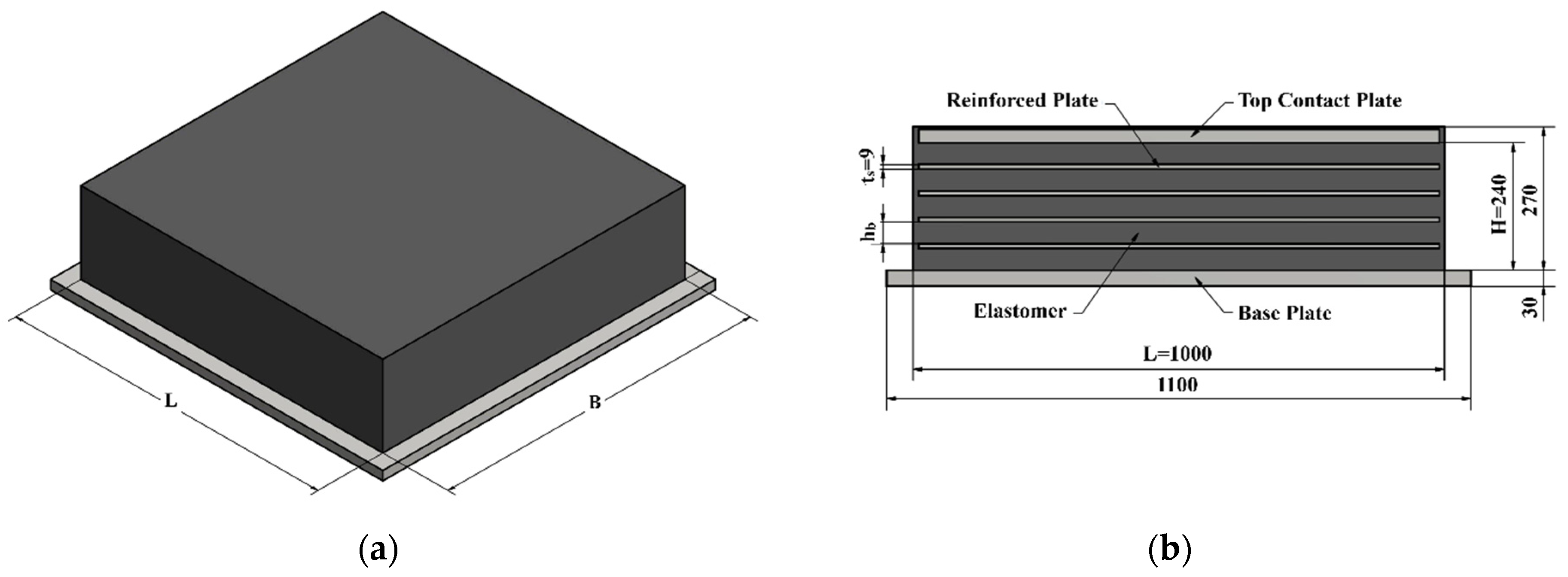
Funding

This research received no external funding.

Conflicts of Interest

The authors declare no conflict of interest.

Appendix A. Comparison between Numerical Simulation and Physical Test

Appendix A.1. Test Model

In order to validate the numerical simulation of the elastomer bearing, first, the shear modulus test according to EN 1337-3 was conducted. Next, finite element analysis was performed under the same conditions, and the results were compared. The size of the bearing model for the comparison is 800 × 800 × 200 mm, with a contact plate of 25 mm thickness at the top and bottom, and 3 reinforcing plates of 6 mm thickness between them. The details of the model are shown in Figure A1.
Figure A1. This is a figure of the schematics of elastomeric bearing for the shear modulus test.
Energies 13 06640 g0a1

Appendix A.2. Test Procedure and Instrument

The shear-modulus test procedure according to EN 1337-3 Annex F is as follows: The test pieces shall be placed symmetrically on each side of the movable plate so that the shear direction is across the width of the bearing. A mean pressure of 6 MPa shall be applied. The bearings shall be subjected to shear at a constant and maximum speed of 150 mm/minute to the maximum test deflection vxm (0.7 Tqvxm ≤ 0.9 Tq) and then returned to zero deflection. The compressive stress shall be removed and the test pieces left undisturbed for five minutes and then shear again to vxm. The horizontal deflection and force shall be recorded continuously or at a minimum of 10 equal intervals during the loading part of the cycle.
The compression/shear test device, specimen, and test setup are shown in Figure A2.
Figure A2. This is a figure demonstrating the test instruments and shear modulus test of the elastomeric bearing: (a) Test instrument (2500 T press and 300 T horizontal actuator); (b) Compression of 6 MPa pressure and shear strain of 0.77 (100 mm).
Energies 13 06640 g0a2

Appendix A.3. Test Results

The test conditions of the shear modulus test according to EN 1337-3 are shown in Table A1. The shear force and displacement graph of the performance evaluation (10 times under the same test conditions) is shown in Figure A3. In the same figure, the result of FE numerical simulation is also given for the same condition. It shows that the present numerical modeling can reasonably represent the physical model so that it can repeatedly be used for the design. More details of the experimental results will be given in the sequel paper.
Table A1. This is a table showing the shear modulus test conditions.
ItemsSpec ConditionsActual Values
Vertical Force, Fz (Pressure)391.8 Tonf (6 MPa)392.5 Tonf (6.01 MPa)
Shear Strain0.7–0.90.77
Test Speed150 mm/min138 mm/min
Figure A3. This is a figure of a comparison of the shear force-displacement graph between performance evaluation (10 times) and FE numerical simulation (shore hardness 50 A).
Energies 13 06640 g0a3
The difference between the experimental and computational results may be attributed to the nonlinear property of the rubber material as an elastomer and the difficulty in numerically modeling the thin layer close to the bonding between reinforcing plates and the elastomer. Despite the small difference, the slopes (stiffness) of the experimental values match well against the computational results. Since the variation of the stiffness of the elastomer with reinforcing plates is the main objective of the current study, the present numerical FE model can be used for that purpose. Nevertheless, to better realize the initial non-linearity of the rubber as in Figure A3, the corresponding shear-angle-dependent material property similar to the measurement needs to be input to the FE modelling.

References

  1. Abe, M.; Yoshida, J.; Fujino, Y. Multiaxial behaviors of laminated rubber bearings and their modeling I: Experimental study. J. Struct. Eng. 2004, 130, 1119–1132. [Google Scholar] [CrossRef]
  2. Nittmannova, L.; Magura, M. Interaction of reinforced elastomeric bearings in bridge construction. Slovak J. Civ. Eng. 2016, 24, 34–40. [Google Scholar] [CrossRef] [Green Version]
  3. Koo, G.H.; Lee, J.H.; Lee, H.Y.; Yoo, B. Stability of laminated rubber bearing and its application to seismic isolation. KSME Int. J. 1998, 13, 595–604. [Google Scholar] [CrossRef]
  4. Wang, R.Z.; Chen, S.K.; Liu, K.Y.; Wang, C.Y.; Chang, K.C.; Chen, S.H. Analytical simulations of the steel-laminated elastomeric bridge bearing. J. Mech. 2014, 30, 373–382. [Google Scholar] [CrossRef]
  5. Zhao, G.; Ma, Y.; Li, Y.; Luo, J.; Du, C. Development of a modified Mooney-Rivlin constitutive model for rubber to investigate the effects of aging and marine corrosion on seismic isolated bearings. Earthq. Eng. Eng. Vib. 2017, 16, 815–826. [Google Scholar] [CrossRef]
  6. Cui, F.; Zhang, H.; Ghosn, M.; Xu, Y. Seismic fragility analysis of deteriorating RC bridge substructures subject to marine chloride-induced corrosion. Eng. Struct. 2018, 155, 61–72. [Google Scholar] [CrossRef]
  7. Yang, C.K.; Bae, Y.H.; Kim, M.H.; Ward, E.G. Loads on tie-down systems for floating drilling rigs during hurricane conditions. J. Offshore Polar Eng. 2010, 20, 1–8. [Google Scholar]
  8. Yang, C.K.; Kim, M.H. The structural safety assessment of a tie-down system on a tension leg platform during hurricane events. Int. J. Ocean Syst. Eng. 2011, 1, 263–283. [Google Scholar] [CrossRef]
  9. Hong, S.K.; Lew, J.M.; Jung, D.W.; Kim, H.T.; Lee, D.Y.; Seo, J.S. A study on the impact load acting on an FPSO bow by steep waves. Int. J. Nav. Archit. Ocean Eng. 2017, 9, 1–10. [Google Scholar] [CrossRef] [Green Version]
  10. Han, D.S.; Jang, S.H.; Lee, G.H. Stiffness evaluation of elastomeric bearings for leg mating unit. J. Korea Acad. Ind. Coop. Soc. 2017, 18, 106–111. [Google Scholar]
  11. Kalfas, K.N.; Forcellini, D. A developed analytical non-lonear model of elastomeric bearing verified with numerical findings. In Proceedings of the Eurodyn, 2020 XI International Conference on Structural Dynamics, Athens, Greece, 23–26 November 2020; pp. 3939–3948, #345262075. [Google Scholar]
  12. Khaloo, A.; Maghsoudi-Barmi, A.; Moeini, M.E. Numerical parametric investigation of hysteretic behavior of steel-reinforced elastomeric bearings under large shear deformation. Structures 2020, 26, 456–470. [Google Scholar] [CrossRef]
  13. Lapidaire, P.J.M. The effect of ship motions on FPSO topsides design. In Proceedings of the Offshore Technology Conference, Houston, TX, USA, 6–9 May 1996; Volume 28, pp. 411–420. [Google Scholar]
  14. BSI. EN 1337-3:2005 Structural Bearings–Part 3: Elastomeric Bearings; BSI: London, UK, 2006. [Google Scholar]
  15. ANSYS Inc. ANSYS Mechanical APDL Material Reference; ANSYS Inc.: Canonsburg, PA, USA, 2012; pp. 47–57. [Google Scholar]
  16. Kang, H.Y.; Kim, M.H. Safety assessment of Caisson transport on a floating dock by frequency- and time-domain calculations. Ocean Syst. Eng. Int. J. 2014, 4, 99–115. [Google Scholar] [CrossRef]
  17. Ward, E.G.; Kim, M.H.; Bae, Y.H. Tie-down Loads for drilling rigs and modules on floating structures. In Proceedings of the OTC (Offshore Technology Conference), Houston, TX, USA, 3–6 May 2010. #20864. [Google Scholar]
  18. Beer, F.P.; Johnston, E.R.; Dewolf, J.T.; Majurek, D.F. Mechanics of Materials, 6th ed.; McGraw-Hill: New York, NY, USA, 2012; pp. 716–725. [Google Scholar]
  19. DNVGL Offshore Standards DNVGL-OS-C101: Design of Offshore Steel Structures, General–LRFD Method; DNVGL: Oslo, Norway, 2016; pp. 22–28.
Figure 1. This is a figure of the schematics of an offshore elastomeric bearing pad: (a) 3D Model of elastomeric bearing for offshore plants; (b) Schematics of elastomeric bearing.
Energies 13 06640 g001
Figure 2. This is a figure of the half-domain finite element model for Analysis: (a) without reinforcing plate; (b) with 4-rows reinforcing plate; (c) with 8-rows reinforcing plate.
Energies 13 06640 g002
Figure 3. This is a figure of the loads and boundary conditions for analysis: (a) Compression; (b) Shear; (c) Bending.
Energies 13 06640 g003aEnergies 13 06640 g003b
Figure 4. This is a figure of the stress distribution of two bearing models with 4-row (left figure) and with 8-row reinforcing plate (right figure): (a) Compression (when vertical displacement is 3 mm); (b) Shear (when horizontal displacement is 50 mm); (c) Bending (when rotation angle is 0.005 rad).
Energies 13 06640 g004aEnergies 13 06640 g004b
Figure 5. This is a figure of the Elastic modulus ratio of elastomeric bearing according to the number of reinforcing plates.
Energies 13 06640 g005
Figure 6. This is a figure demonstrating the compression coefficient of elastomeric bearing according to each elastomer height.
Energies 13 06640 g006
Figure 7. This is a figure of the Shear modulus ratio of elastomeric bearing according to the number of reinforcing plates when vertical displacement of 3 mm and horizontal displacement of 50 mm are imposed.
Energies 13 06640 g007
Figure 8. This is a figure demonstrating the bending modulus ratio of elastomeric bearing according to the number of reinforcing plates when the rotation angle is 0.005 rad.
Energies 13 06640 g008
Figure 9. This is a figure demonstrating the stiffness ratios of bearing as a function of the number of reinforcing plates: (a) compression condition; (b) shear condition; (c) bending condition.
Energies 13 06640 g009aEnergies 13 06640 g009b
Figure 10. This is a figure showing the FPSO global axis system.
Energies 13 06640 g010
Figure 11. This is a figure showing the half-domain finite element model of vertical elastomeric bearing for FPSO.
Energies 13 06640 g011
Figure 12. This is a figure showing the stress distribution for steel plate (left figure) and elastomers (right figure) of vertical bearing under compression: (a) SLS load condition; (b) ULS load condition; (c) ALS load condition.
Energies 13 06640 g012
Table 1. This is a table, Mechanical properties for S355 structural steel (EN 10025-2).
ItemsSignUnitValue
Young’s ModulusEGPa200
Poisson’s RatioN-0.29
Yield StrengthσYMpa355
Ultimate StrengthσUMpa510–680
Table 2. This is a table of the mechanical properties for Neoprene sheet (Shore hardness 50–60 A).
ItemsSignUnitValue
Mooney–Rivlin ConstantsC10Mpa0.382
C1Mpa0.096
Poisson’s Ratioν-0.49
Tensile (Ultimate) StrengthσUMpa15.0
Table 3. This is a table illustrating the maximum stress for reinforcing steel plate of bearing according to the number of plates under a compression load (unit: MPa).
Vertical Disp. (Dz)Number of Reinforcing Plate (Ns)
012345678
1 mmN/A4.47.311.015.521.328.437.448.8
2 mmN/A8.914.622.131.342.957.375.598.5
3 mmN/A13.322.133.447.364.886.6114.2149.2
4 mmN/A17.829.744.863.587.0116.5153.7200.9
5 mmN/A22.437.456.379.9109.6146.9194.0253.8
Table 4. This is a table of the maximum stress for elastomer of bearing according to the number of plates under the compression load (unit: MPa).
Vertical Disp. (Dz)Number of Reinforcing Plate (Ns)
012345678
1 mm0.060.080.130.190.260.340.440.550.69
2 mm0.110.170.270.390.530.700.901.151.47
3 mm0.170.250.400.590.811.081.411.852.42
4 mm0.220.330.540.791.101.492.002.673.59
5 mm0.280.420.691.011.421.952.673.655.02
Table 5. This is a table of the safety factor for reinforcing steel plate of bearing according to the number of plates under the compression load.
Vertical Disp. (Dz)Number of Reinforcing Plate (Ns)
012345678
1 mmN/A80.548.832.322.816.712.59.57.3
2 mmN/A40.124.216.011.38.36.24.73.6
3 mmN/A26.716.110.67.55.54.13.12.4
4 mmN/A19.912.07.95.64.13.02.31.8
5 mmN/A15.99.56.34.43.22.41.81.4
Table 6. This is a table of the safety factor for elastomer of bearing according to the number of plates under the compression load.
Vertical Disp. (Dz)Number of Reinforcing Plate (Ns)
012345678
1 mm272.2182.5113.078.357.543.934.327.221.8
2 mm135.690.956.238.928.521.516.613.010.2
3 mm90.260.337.125.618.613.910.68.16.2
4 mm67.645.027.618.913.610.17.55.64.2
5 mm53.835.821.814.810.67.75.64.13.0
Table 7. This is a table illustrating the vertical forces (Fz) of elastomeric bearing according to the number of reinforcing plates (unit: MN).
Vertical Disp. (Dz)Number of Reinforcing Plate (Ns)
012345678
1 mm0.040.190.450.891.572.553.965.948.69
2 mm0.090.380.921.813.185.198.0712.1117.72
3 mm0.130.581.402.764.857.9212.3118.5027.10
4 mm0.180.791.893.746.5710.7416.7125.1336.86
5 mm0.221.002.404.748.3413.6521.2832.0347.03
Table 8. This is a table showing the compression stiffness (Kc) of elastomeric bearing according to the number of reinforcing plates (unit: kN/mm).
Vertical Disp. (Dz)Number of Reinforcing Plate (Ns)
012345678
1 mm4319045489315662554396559448689
2 mm4319246190715912597403460538859
3 mm4419446792016162640410561669033
4 mm4419747493416422685417962849216
5 mm4419948094816692731425564079407
Table 9. This is a table showing the compression resultant of elastomeric bearing according to the number of reinforcing plates.
Compression ResultantNumber of Reinforcing Plate (Ns)
012345678
Hb (mm)240231222213204195186177168
hb (mm)240115.574.053.340.832.526.622.118.7
Kc (kN/mm)4419446792016162640410561669033
RKc (-)1.04.410.620.936.760.093.3140.1205.3
Ec (MPa)10.644.8103.7196.0329.7514.8763.51091.41517.5
Rc (-)1.04.29.818.631.248.872.3103.4143.7
Table 10. This is a table showing the Shear resultant of elastomeric bearing according to the number of reinforcing plates when horizontal displacement of 50 mm and vertical displacement of 3 mm are imposed (unit: kN).
Shear ResultantNumber of Reinforcing Plate (Ns)
012345678
Fx (kN)190.5196.0203.2210.6218.0225.3232.2238.4243.4
Ks (kN/mm)3.813.924.064.214.364.514.644.774.87
RKs (-)1.001.031.071.101.141.181.221.251.28
G (MPa)0.910.910.900.900.890.880.860.840.82
Rs (-)1.001.000.990.990.980.970.950.920.90
Table 11. This is a table showing the bending resultant of elastomeric bearing according to the number of reinforcing plates when the rotation angle is 0.005 rad.
Bending ResultantNumber of Reinforcing Plate (Ns)
012345678
My (kN-m)10.125.745.768.291.9177.1145.2177.4215.6
Kb (kN-m/rad)20255139913113,63018,37323,42929,03135,48343,128
RKb (-)1.02.54.56.79.111.614.317.521.3
Eb (MPa)5.814.224.334.845.054.864.875.486.9
Rb (-)1.02.44.26.07.79.411.112.914.9
Table 12. This is a table of the compressive, shear, and bending stiffness of elastomeric bearing according to the number of reinforcing plates.
StiffnessNumber of Reinforcing Plate (Ns)
012345678
Kc (kN/mm)4419446792016162640410561669033
Ks (kN/mm)3.813.924.064.214.364.514.644.774.87
Kb (kN-m/rad)20255139913113,63018,37323,42929,03135,48343,128
Table 13. This is a table showing the stiffness ratio of elastomeric bearing according to the number of reinforcing plates.
Stiffness RatioNumber of Reinforcing Plate (Ns)
012345678
RKc = Kc/Kc01.04.410.620.936.760.093.3140.1205.3
RKs = Ks/Ks01.001.031.071.101.141.181.221.251.28
RKb = Kb/Kb01.02.54.56.79.111.614.317.521.3
Table 14. This is a table showing the LRFD combinations.
ItemsLoad CombinationsLoad ConditionsSafety Factor
Ultimate Limit States (ULS)1.3 × Permanent Loads + 0.7 × Environmental LoadsTransit (Tow)
100-yr Extreme
>1.67
Accidental Limit States (ALS)1.0 × Permanent Loads + 1.0 × Environmental Loads10,000-yr Abnormal
1-yr Damaged
>1.33
Serviceability Limit States (SLS)1.0 × Permanent Loads + 1.0 × Environmental Loads1-yr Operating>3.0 *
* Safety factor of 3.0 is required against failure within the design life.
Table 15. This is a table showing the load and displacement conditions applied to elastomeric bearing for FPSO.
Load ConditionsFx (kN)Fy (kN)Fz (kN)Dx (mm)θy (rad)
ULSTransit (Tow)3055546016,523200.003
100-yr Extreme5991816021,820260.005
ALS10000-yr Abnormal777811,66424,877330.007
1-yr Damage6124967122,83927N/A
SLS1-yr Operating4244500918,323190.002
CompressionShearBending
Table 16. This is a table of the dimensions for the analytic model.
ItemsDimensions
Overall Size1100 × 1100 × 300 mm
Base Plate1100 × 1100 × 30 mm
Elastomeric Bearing1000 × 1000 × 270 mm
Top Contact Plate980 × 980 × 25 mm
Reinforcing Plate980 × 980 × 9 mm (7-rows)
Table 17. This is a table shoing the maximum stresses and safety factors of vertical bearing under compression and shear load.
ItemsReinforcing Steel PlateElastomerRemarks (Safety Factor)
Stresses (MPa)Safety FactorStresses (Mpa)Safety Factor
CompressionSLS113.43.132.426.20>3.0
ULS133.92.353.244.63>1.67
ALS151.62.344.123.64>1.33
ShearSLS113.43.132.426.20>3.0
ULS133.92.653.244.63>1.67
ALS151.62.344.123.64>1.33
BendingSLS51.96.840.1788.8>3.0
ULS130.22.730.4334.9>1.67
ALS182.61.940.6124.7>1.33
Yield strength of steel plate: 355 Mpa, Tensile strength of elastomer: 15 Mpa.
Table 18. This is a table showing the stiffness of vertical bearing according to load conditions.
Load ConditionsMax. LoadDisplacementStiffness
CompressionSLS18,323 kN2.98 mm6149 kN/mm
ULS21,850 kN3.51 mm6225 kN/mm
ALS24,877 kN3.96 mm6282 kN/mm
ShearSLS90 kN19 mm4.74 kN/mm
ULS120 kN26 mm4.62 kN/mm
ALS148 kN33 mm4.49 kN/mm
BendingSLS70.8 kN-m0.002 rad35,390 kN-m/rad
ULS177.4 kN-m0.005 rad35,483 kN-m/rad
ALS249.1 kN-m0.007 rad35,589 kN-m/rad
Publisher’s Note: MDPI stays neutral with regard to jurisdictional claims in published maps and institutional affiliations.

