Abstract
Increasing production of waste has compelled the development of modern technologies for waste management. Certain fractions of municipal solid wastes are not suitable for recycling and must be utilised in other ways. Materials such as refuse-derived fuel (RDF) fractions are used as fuel in cement or CHP (combined heat and power) plants. The low bulk density leads to many problems pertaining to transportation and storage. In the case of biomass, these problems cause reduction in pelletisation. This paper therefore presents a comprehensive study on RDF pellet production, which is divided into three major areas. The first describes laboratory-scale tests and provides information on key factors that affect pellet quality (e.g., density and durability). Based on this, the second part presents a design of modified RDF dies to form RDF pellets, which are then tested via a semi-professional line test. The results show that RDF fraction can be compacted to form pellets using conventional devices. Given that temperature plays a key role, a special die must be used, and this ensures that the produced pellets exhibit high durability and bulk density, similar to biomass pellets.
1. Introduction
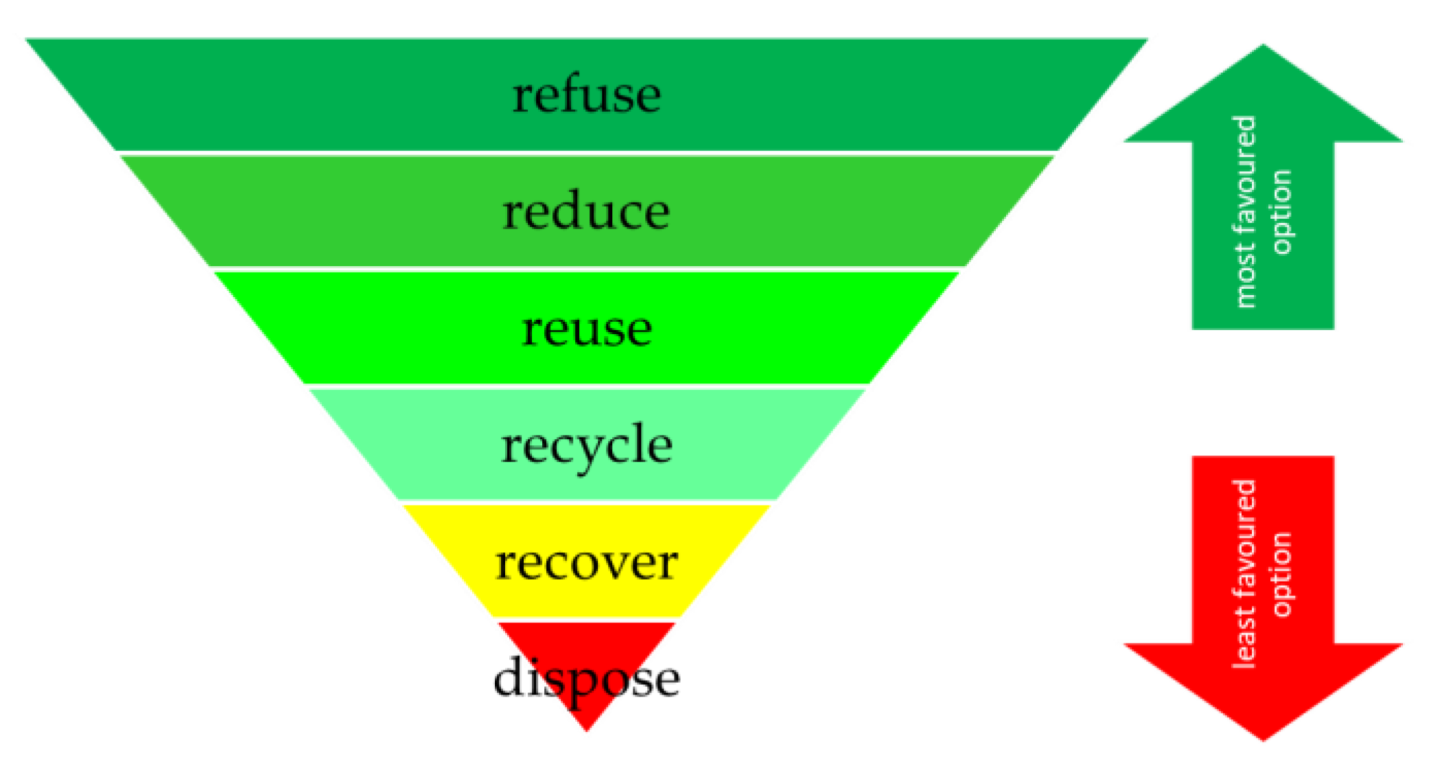
The current model for waste management in Poland assumes that waste is pre-sorted at, or near, its place of production. Polish and European laws regulate the possible application of waste-derived materials. Figure 1 shows the waste hierarchy where prevention (i.e., reduction) takes the highest level of priority. Re-use and recycling of waste as well as energy recovery are ranked next [1]. Finally, landfilling ranks last, being the least favoured method of waste processing. Energy recovery is realised by incineration plants, cement plants, and CHP (combined heat and power) plants [2,3,4,5,6,7]. Incineration plants are usually equipped for the waste stream produced by communities. By contrast, cement and CHP plants are more challenging because they require high-quality fuel. In particular, they require conditions of high HHV (higher heating value) as well as low moisture, chlorine, and sulphur content. In Poland, approximately 30% of material, classified as refuse-derived fuel (RDF) or solid refused fuel (SRF), is applied to cement plants [8,9]. The remaining stream is incinerated. Solutions for recovery from municipal solid waste (MSW) streams with energetic potential and processing are needed. It is important that the resulting fuel is attractive to other sectors of the energy economy, especially specialised CHP plants [10,11,12].
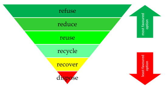
Figure 1.
Waste hierarchy schematic [15,16].
Mechanical–biological treatment (MBT) plants produce most of the Polish RDF fraction from municipal solid waste (MSW) [13]. These units use a combination of separation, drying, and biological processes for the treatment. The first process involves sieving of the particles on drum screens, with various mesh sizes (from 50 to 100 mm), which enables separation of fine particles. The oversized fraction (particles remaining on the drum screen) can be dried (if necessary) and processed. The undersized fraction contains a significant amount of organic matter. In most cases, this fraction is composted or undergoes other forms of biological treatment, while the oversized fraction is sent for energy recovery [14]. Previous studies have shown that the morphological composition of this fraction can vary. Even in a single region, it can vary based on the time of year [2]. MSW comprises organic matter, minerals (including glass), plastics, textiles, paper, and cardboard. The last four materials are mainly present in the oversized fraction. These are materials with high energy parameters (low ash content and high calorific value) favourable for waste-based fuel.
According to literature [17,18,19,20], the mixed MSW fraction in Poland is very inhomogeneous. This material is dependent upon regional characteristics and residents’ customs. Urban areas, characterised by highly dense social and economic infrastructure, account for the highest production of RDFs/SRFs. From 1000 g of MSW, it is possible to achieve approximately 500 g of RDF/SRF. Areas with a high proportion of single-family houses can generate up to 380 g, whereas rural areas can produce only 270 g per kg of MSW.
The growing interest in using MSW as an energy source is limited by homogenisation and low bulk density. A comparison between the bulk densities of RDF and other popular materials is shown in Figure 2. These issues, in the case of biomass, are overcome by densification processes [21,22]. These processes increase the bulk density by producing pellets or briquettes. Such fuel is more favourable for transport and storage. Literature describes that the usage of pellet instead of loose RDF would improve the production of cement [23]. It also appears to be a sought-after fuel for CHP plants [24]. Due to the higher bulk density, such fuel will be more beneficial in other thermal treatment processes such as gasification [25], pyrolysis [26,27], or even torrefaction [28]. Pellet production also leads to quality uniformity of the produced fuel. Like biomass, RDF fuel can also be compacted, but it requires special attention. The morphology of the MSW-based material is different from that of biomass. Biomass is composed of natural polymers: cellulose, hemicellulose, and lignin, and lignin acts as a natural binder during the densification of biomass [29,30,31,32,33]. However, such binders do not occur in RDF, so its potential for densification must be checked. The introduction of artificial binders is not desired, and may moreover be impossible to achieve. Such substances can change the fuel quality parameters and increase the cost of the fuel [34,35].

Figure 2.
Comparison of bulk densities of fuel materials [32,36,37,38].
Other important factors for densification are grindability and grain size distribution (after milling) [39]. An oversized fraction is troublesome during conventional milling. Owing to the high share of elastic and fibrous materials, dedicated devices are needed, a requirement that is often realised upon using several knife mills working in a cascade mode. However, the achieved material is still not as fine as biomass grist, as illustrated in Figure 3. The grain size distribution is a major parameter that affects pellets production [40]. During biomass pelletisation, the rollers that move across the die also grind the particles. Given that biomass is more brittle than RDF, this process should not pose a significant issue. Another factor is moisture content, which is a major parameter in the densification of biomass. In both cases, drying is used. Based on literature, the levels of moisture range from 10% to 20%, with respect to mass [41,42,43]. Many studies have covered the agglomeration of biomass [44,45,46]. However, only a few have covered the problems connected with MSW-based pellet production [47]. The die temperature is often above 100 °C and is a result of dissipated energy from friction between the die, rollers, and material [48]. High friction results in higher temperatures, up to a limit. When the temperature becomes too high, carbonisation occurs on the pellet surface, which is specific to the material used. Given that the temperature is a result of die geometry, in general, it is not a point of interest for manufacturers. Friction increases with the die thickness or channel entry angle, which both affect the resistance generated during the pressing of material through the matrix channels.

Figure 3.
Grain size distribution comparison of biomass and refuse-derived fuel (RDF) grists from a knife mill [49]. Payne, 2006 is optimal grain size distribution to produce high quality biomass pellets [40].
Based on this, the main aim of this study was to develop an effective technology to produce pellets from RDF. We assumed that the majority of this product will go to CHP plants. Thus, larger pellet diameters are acceptable, such that the final product will be pellets with diameter greater than 6 mm (typical size of biomass pellets).
As in the case of biomass, it is important to determine all aspects of the process that affects product quality. The main challenge is to reduce the importance of feedstock patchiness, so the difference in morphology, grain size distribution, or even moisture content must be considered. Thus, rigorous research is needed. First, we conducted our analysis based on the selected process parameters: durability and density. Next, we carried out a small-scale test on a modified die. Then a semi-professional line test was carried out, to verify all aspects of this study.
2. Materials and Methods
For all research phases, the oversized MSW fraction was obtained from a local MBT plant (Kraków, Poland). This material was collected in spring, 2018. This was a high-quality fraction, which is used as RDF for a cement plant after milling. The morphological structure of this material is detailed in [2]. Given that MSW is composed of bulky materials, such as plastic elements or textile cloths, it must be shredded. For this, we used a knife mill (MF-4, Protechnika, Poland) with a mesh size of 10 mm, which is typical for RDF. Before grinding was performed, all hard materials, such as rocks, metal elements, or glass, were removed. The produced grist was then sieved to determine grain size distribution. This was assessed using a sieve shaker (LPzE-4e, Multiserw-Morek, Poland) equipped with 6, 3.15, 2, 1.4, 1, and 0.5 mm sieves (Multiserw-Morek, Poland). Next, the material was conditioned in the constant climate chamber (KBF-S 115, Binder, Germany) under controlled temperature and humidity conditions. This allows us to acquire consistent moisture content throughout the study. According to literature [42], we chose 18% as the most suitable moisture content value.
2.1. Laboratory-Scale Densification
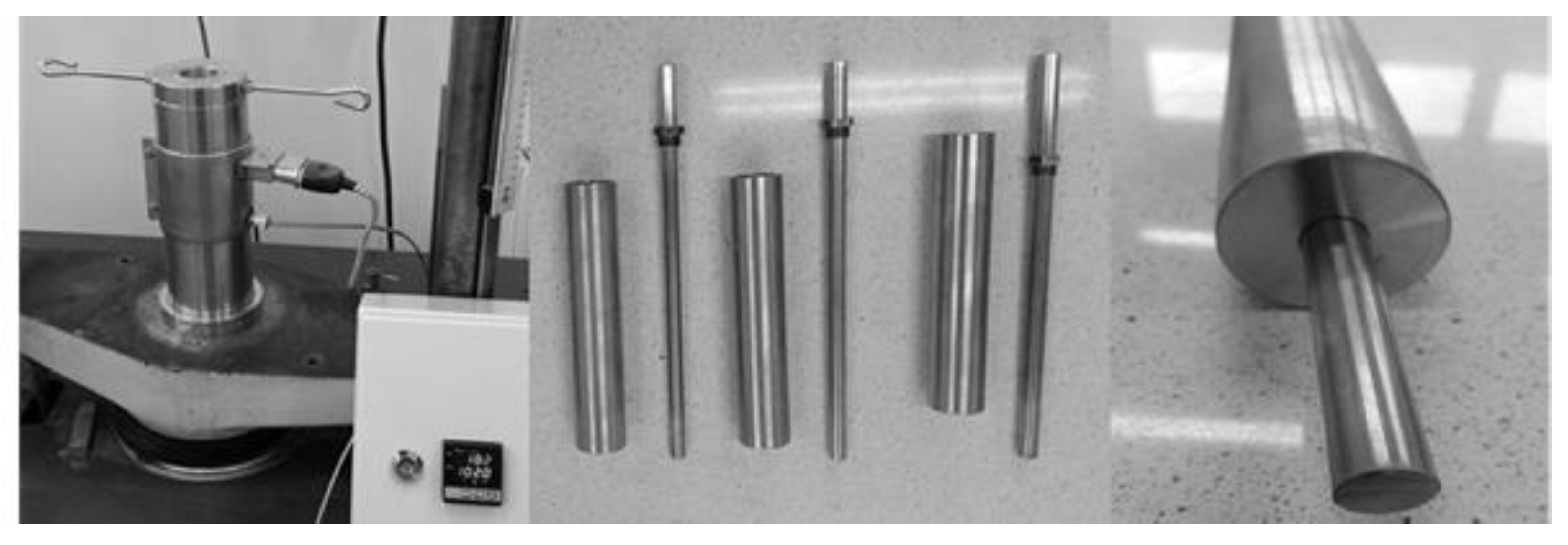
For the laboratory-scale densification, we used the universal testing machine (EDZ 20 Type, VEB “Fritz-Heckert”, Germany) with special appliance. This appliance consists of several elements, as shown in Figure 4. The main component consists of the die and piston, which can be changed for different pellet diameters. In this study, we employed three diameters: 16, 18, and 20 mm. With the testing machine, we obtained precise information about the force used to compress the material. This value is converted to pressure, using the piston base area. In the laboratory test, according to the literature, we selected five pressure levels: 80, 100, 120, 140, and 160 MPa. Table 1 presents the calculated force values needed to achieve the desired pressure levels. The heating band, mounted on the outer sleeve, heats up both the sleeve and die. The high mass of this assembly (approximately 5 kg), results in high thermal inertia, which stabilises the temperature during tests. A proportional-integral-derivative system controls the temperature, using two thermocouples. Based on literature and our assumptions, we selected three temperature levels: 80, 100, and 120 °C. The upper temperature value is limited by both the melting point of the plastics and the die temperature achieved during normal pellet production [32,50].
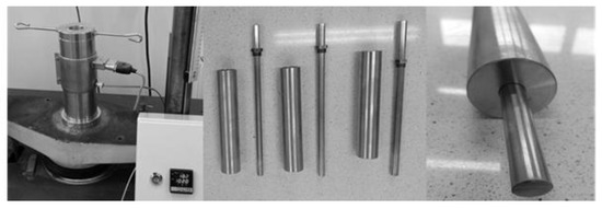
Figure 4.
Laboratory-scale compaction stand for pellet production.

Table 1.
Compaction pressure levels with forces for different die diameters.
A total of 45 combinations of die diameter, pressure, and temperature were tested. To ensure quality of our results, we produced five sets of granules for each test. This resulted in the production of 225 pellets in total. All samples were produced from a similar mass of 4 g of RDF grist.
2.2. Laboratory-Scale Analysis
After densification, we measured the height, diameter, and mass of the individual granules. After this, we placed the samples into individually labelled compartments to prevent any misidentification during later measurements.
All samples were left for 24 h, to determine the relaxation (expansion) factor R, which is a popular quantity for biomass pellets. It provides information about the height changes after 24 h as it is normal for biomass granules to expand after densification [51]. It is given by
where R is the expansion coefficient, h0 is the pellet height immediately after the production process, and h24 is the pellet height after 24 h. This quantity gives information how strong bonding forces between particles are. For elastic materials, R will have higher values than rigid ones.
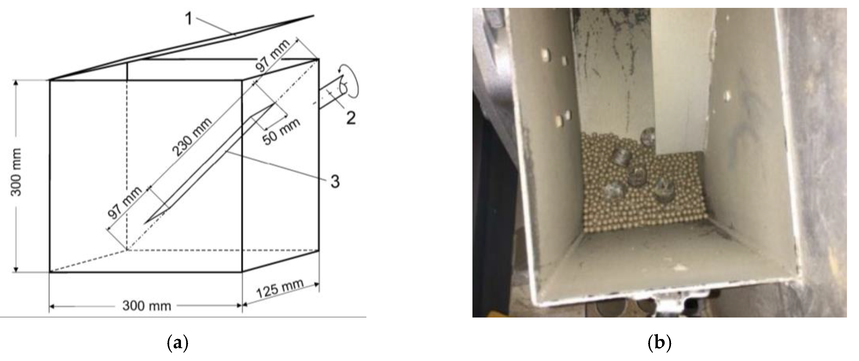
Mechanical durability is a crucial parameter concerning transport and logistics. Many standards refer to this quantity [52]. In general, as described in methods, we required about 500 g of pellets per test. In laboratory scale we produced only five granules (20 g) in each condition. The small number of samples was dictated by their time-consuming production. Assuming that two people worked at this stage, it took about 2–4 min to produce one pellet. This gives an average of 12 man-hours for one full series of samples (500 g), which in our case was a total of 45 combinations. That is why we could not use such methods without modifying them. We used equipment described in the ISO 17831-1:2016-02 [53] standard, as shown in Figure 5, which simulates the damage to particles during transportation. The main component is a cuboidal chamber with two baffles inside. The box rotates at 50 rpm for 10 min. Given that we used only five granules, we filled the box with ABS (acrylonitrile butadiene styrene) balls 5 mm in diameter, to meet the 500 g noted in the standard [54]. ABS balls were chosen, as they are durable, and have similar specific density to RDF pellets. The principle of operation of the balls should be similar to that used for smoothing the edges of metal castings. After the process, we removed and weighed the granules. The mechanical durability DU is given by
where mE and mA is mass of the sample before and after testing, respectively [53]. Please note that this value is only for comparison within this study, so reference with other pellets is not possible. Further research on this method is in progress.
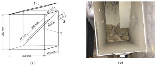
Figure 5.
Mechanical durability machine: (a) measurement box schematic [53] and (b) image of samples immersed in ABS (acrylonitrile butadiene styrene) balls.
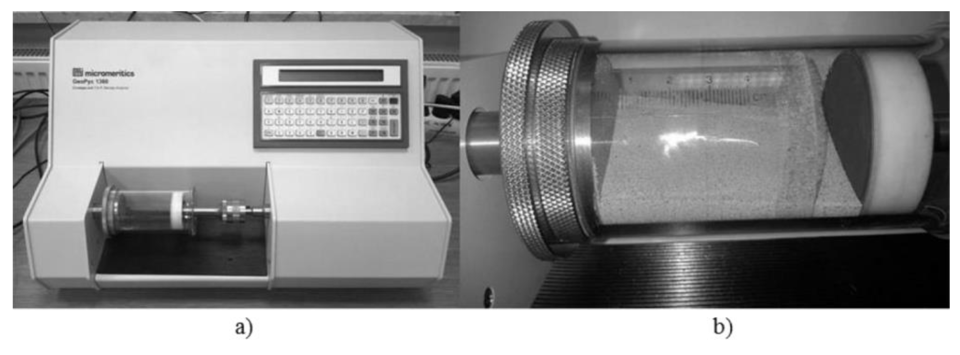
The specific density of the obtained agglomerates was measured using a quasi-fluid pycnometer (GeoPyc 1360, Micromeritics, USA). The device measures the volume of a sample placed in the measuring chamber, using the DryFlo (Micromeritics, USA) quasi-fluid agent. Using a dry agent, instead of a liquid, eliminates the wetting phenomenon (i.e., soaking) of the tested material. This makes it possible to test very absorptive materials. The pycnometer is shown in Figure 6a. First, the device determines the volume of agent placed in the chamber (Figure 6b) of known diameter, based on the piston travel measurement. Then, the sample is added, and the total volume is determined. The volume of the sample is determined by the difference between the total volume and the agent volume. The device also automatically calculates the density, given that the mass and volume are known. It is possible to set the precise force that the piston will apply to press the material inside the chamber, which enables determination of the volume of substances with low compressive strength.
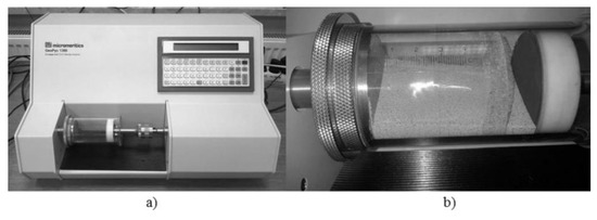
Figure 6.
GeoPyc 1360 pycnometer: (a) general view and (b) measuring chamber.
2.3. Die Design
As RDF differs from biomass, a special die geometry must be proposed. The laboratory-scale tests confirmed that temperature plays a key role in the densification process. To determine the temperature of the standard biomass die, when RDF is used as the feedstock, we used an infrared (IR) camera (T600 Series, FLIR, USA). As the die moves at high rpm, temperature measurement techniques are limited. Thus, a camera was used to visualise the temperature of the die. In this application, we only need information about the range of temperature. A picture of the element is taken after several minutes of stable operation, to ensure that all parts reach their working temperature. We carried out a similar test for the modified die. From the acquired thermographs, we redefined the die dimensions.
2.4. Test on Professional Machinery
Data taken during the laboratory-scale test were used for the new die design, which should enable the production of high-quality RDF pellets. The redesigned matrix was then tested on a small-scale flat die pelletiser (MGL 200, KovoNovak, Czech Republik). For reference, we used a normal die for biomass pelletisation. We analysed the bulk density and mechanical durability, using the relevant standards. The determination of bulk density (BD) was carried out following the ISO 17828:2015 standard [55]. We used containers of volume 0.005 m3 for pellets, and 0.05 m3 for RDF grist. These results were used to determine how the bulk density changes during the process. For a better understanding of the process, we also took tomographic pictures using the IR camera. The temperature of the die’s surface and pellets were monitored during operation. Data from the thermographs were used to confirm the effects of the design process.
The final tests were on a semi-professional line, based on ring-die pelletiser, which was equipped with all unit operations needed for pellet production. This includes drying, milling, storage, densification, and separation processes. The semi-professional line was equipped with our new die design. Due to strength issues, we were not able to produce dies with the same channel diameter. The small part width reduced the largest possible diameter to 8 mm. All other concepts, such as channel length to diameter ratio, were maintained. In this test, we were also able to acquire bulk density and durability information.
3. Results
3.1. Raw Material Analysis
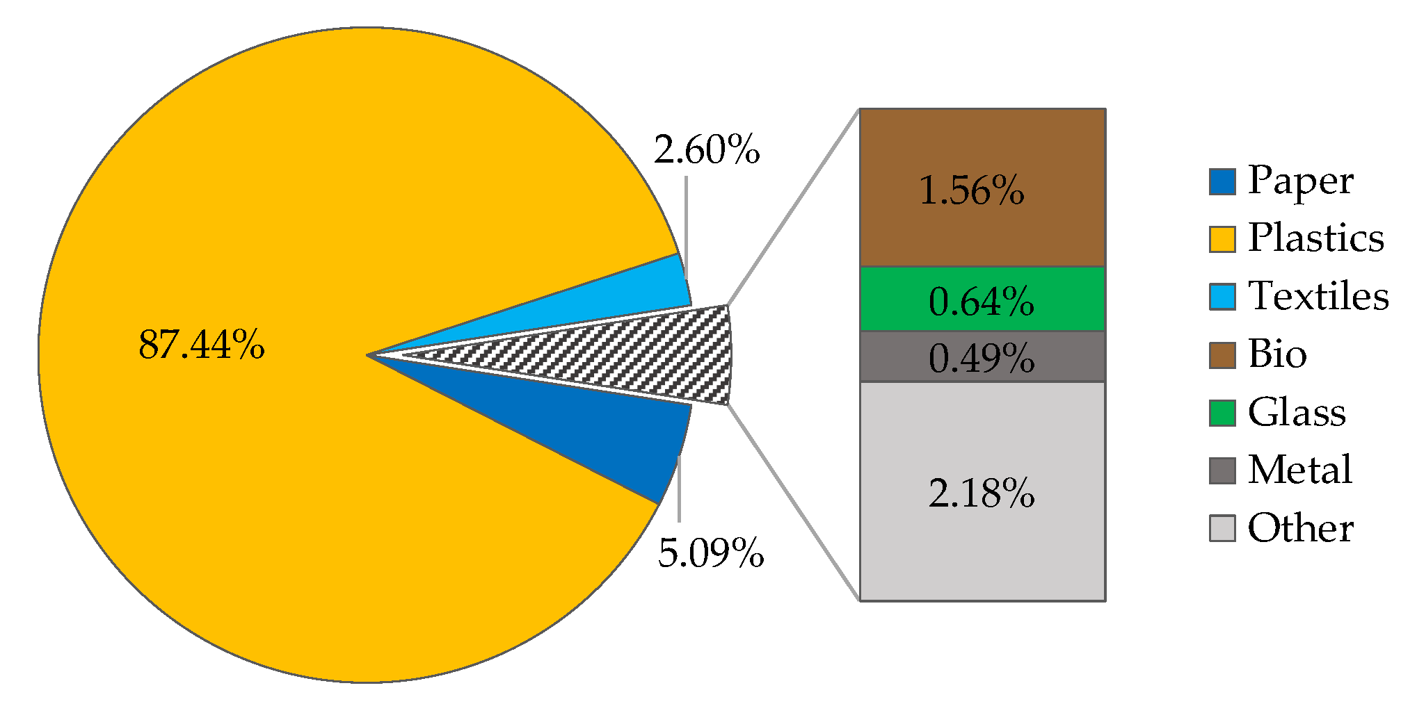
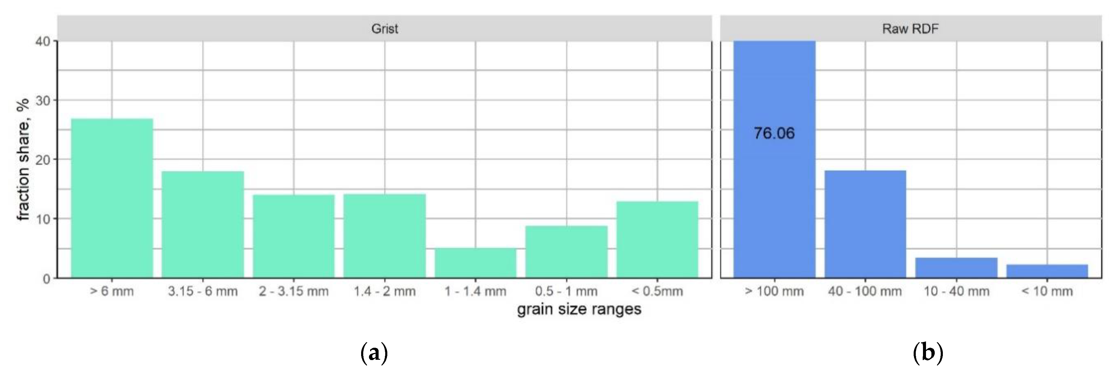
Figure 7 presents the morphology of the waste stream we used in this study. The high share of plastics is normal because the RDF is formed of the oversized fraction. Before any further analysis, all visible elements of glass, metal, and minerals that could damage the mill elements were removed. Grain size analysis, before and after milling, is shown in Figure 8. It confirms what has been suggested in the literature; that RDF is a difficult material for milling. The dominant fraction is over 6 mm. These were thin and flexible plastic foils and textiles, which are very hard to cut in the knife mill.
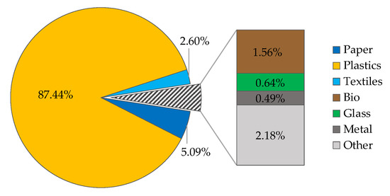
Figure 7.
Morphology of the material used in this study.
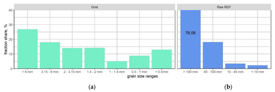
Figure 8.
Comparison of RDF grain size distribution after milling (a), and before (b).
3.2. Laboratory-Scale Densification
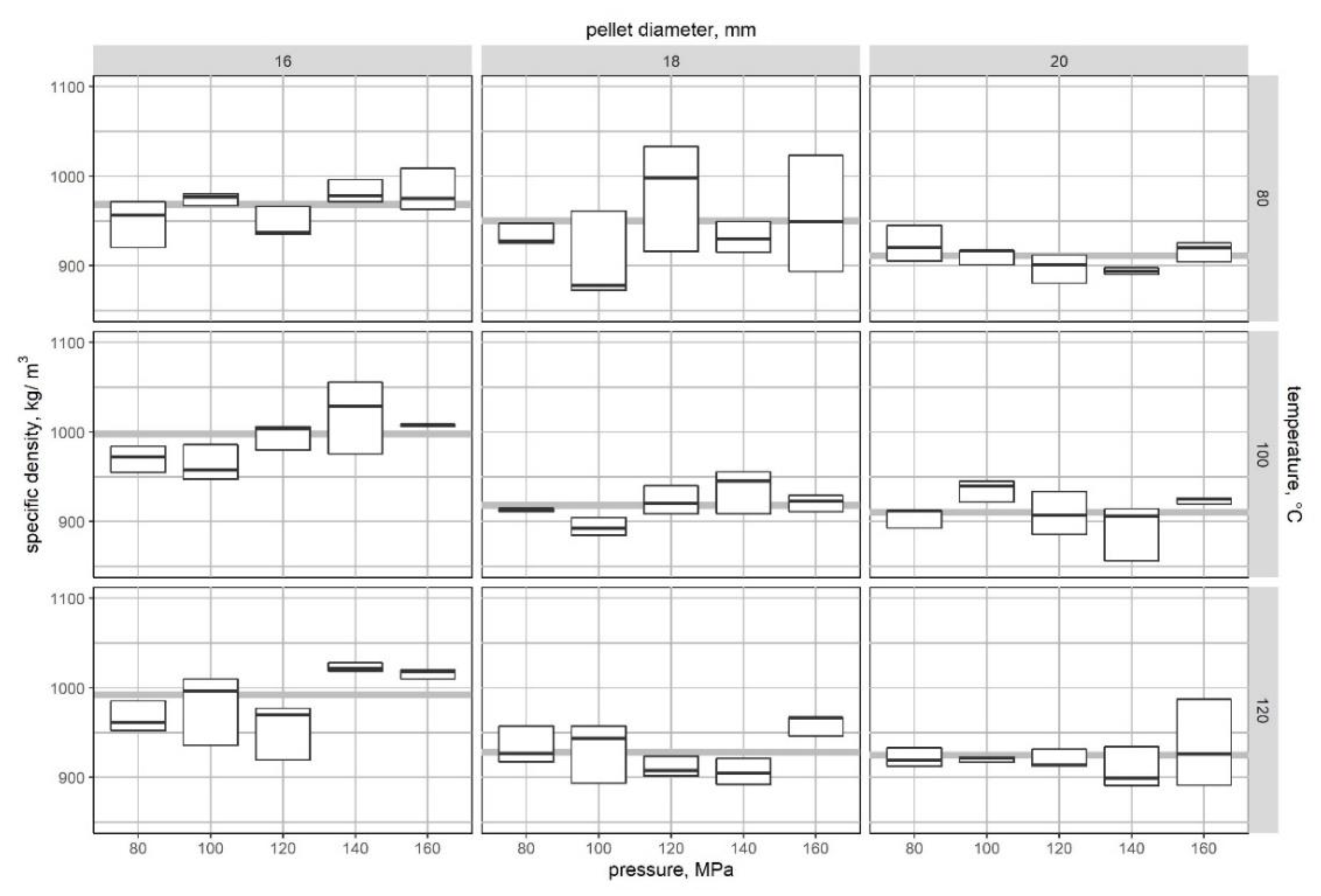
Owing to the small number of pellets produced from each series, all granules were treated with care. Figure 9 shows the specific density for all pellets grouped by diameter and temperature. Each box represents an average value of the five samples grouped by pressure. The average value for the group is also indicated in each plot. The best pellets should have the highest specific density. The results show that it is hard to achieve granules with stable density value, even in recurring laboratory conditions. Analysis of the average values provides initial information about the trends.
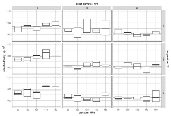
Figure 9.
Variation of specific density with compaction pressure, temperature, and pellet diameter. The grey line in each plot represents the average value of each group. Top and bottom of each box represents range of values deviation.
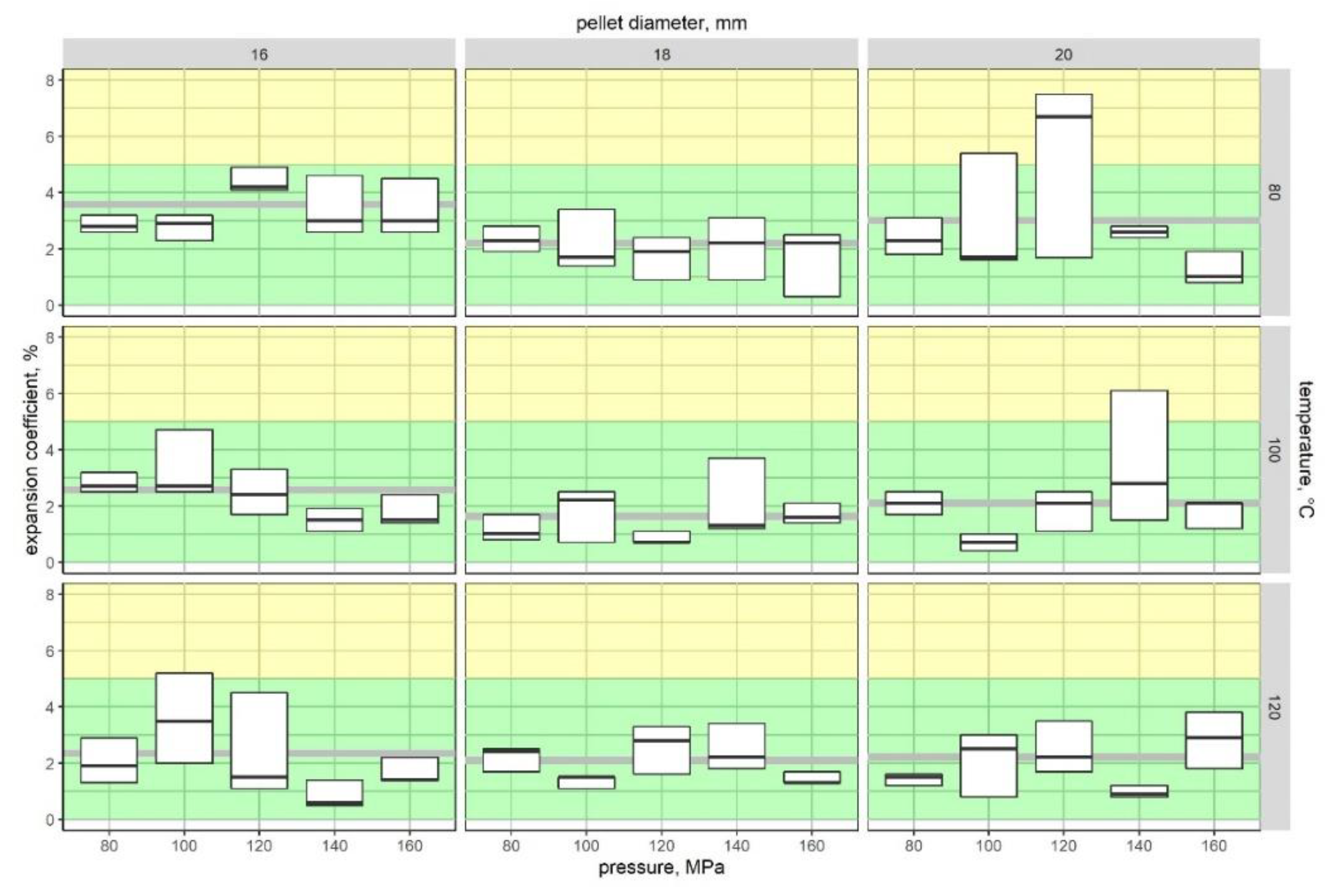
After 24 h, the expansion coefficient of the samples was considered according to height change. Exemplary pellets with our quality criterion are shown in Figure 10. We have attributed high-quality pellets as having an expansion coefficient less than or equal to 5%. The appearance of the samples and the ranges used in this test are shown in Figure 10. The cumulative results are shown in Figure 11. As for Figure 9, average values are also indicated by grey lines. As for the density analysis, values for the same pressure group vary.

Figure 10.
Pellet quality criterion based on the expansion coefficient.
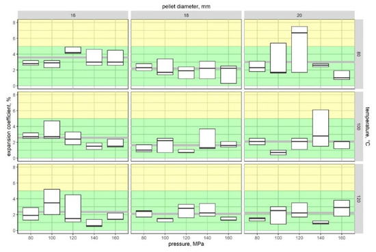
Figure 11.
Variation of the expansion coefficient with compaction pressure, temperature, and pellet diameter. The grey line in each plot represents the average value of each group. Top and bottom of each box represents range of values deviation.
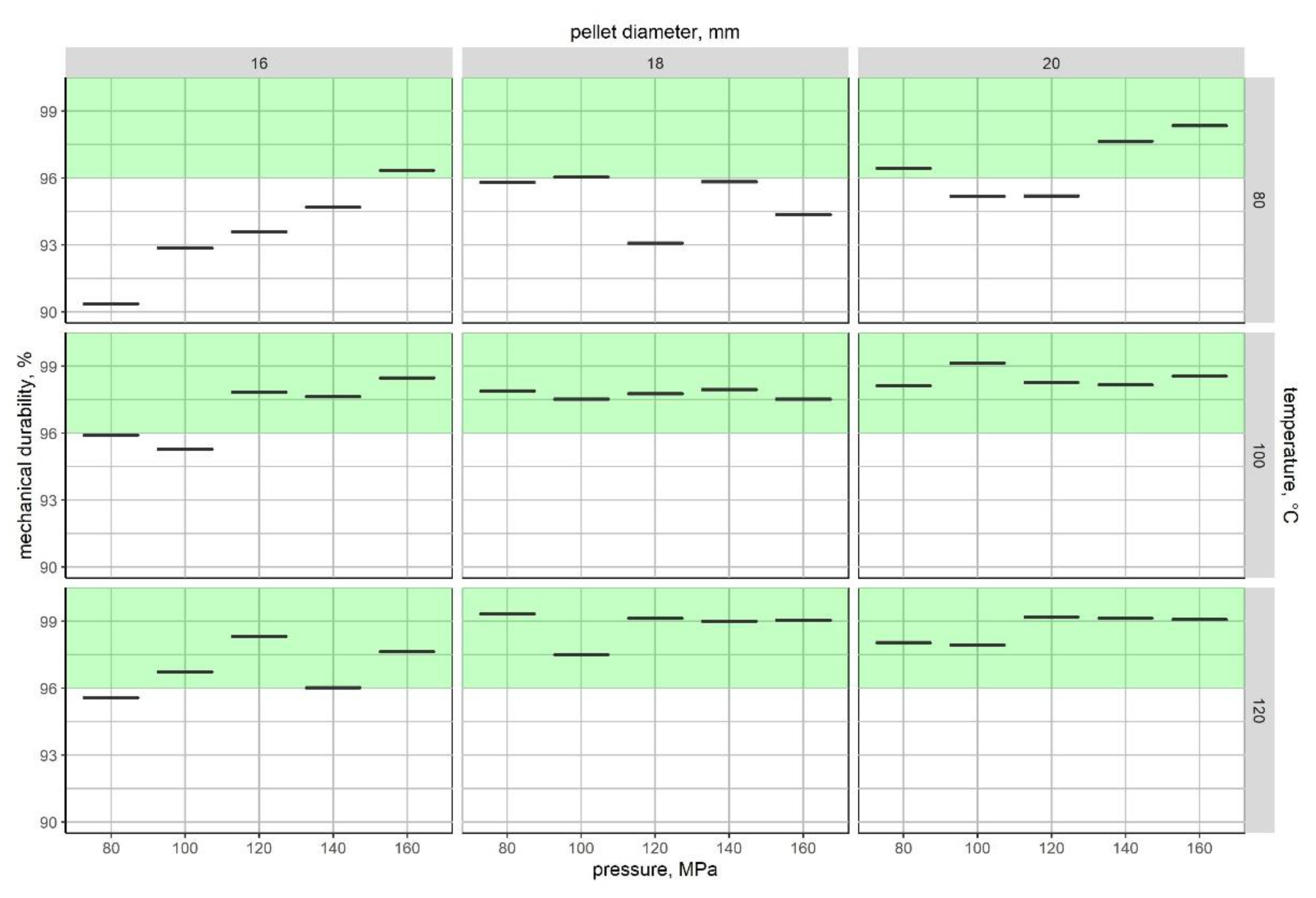
The mechanical durability results, based on our modified method, are shown in Figure 12. According to biomass pellets standards, all samples with durability higher than 96% were considered to have high quality.
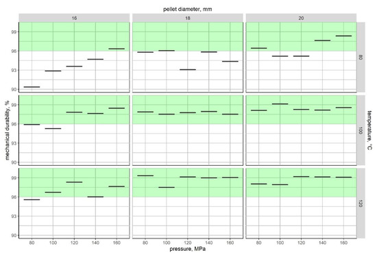
Figure 12.
Variation of the mechanical durability with compaction pressure, temperature, and pellet diameter.
3.3. RDF Die Design
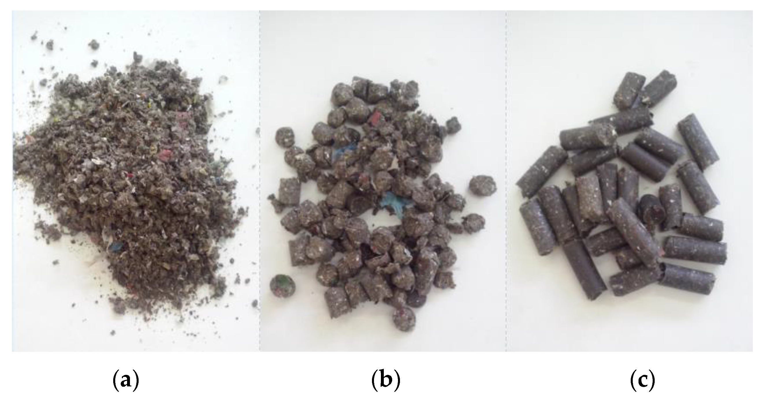
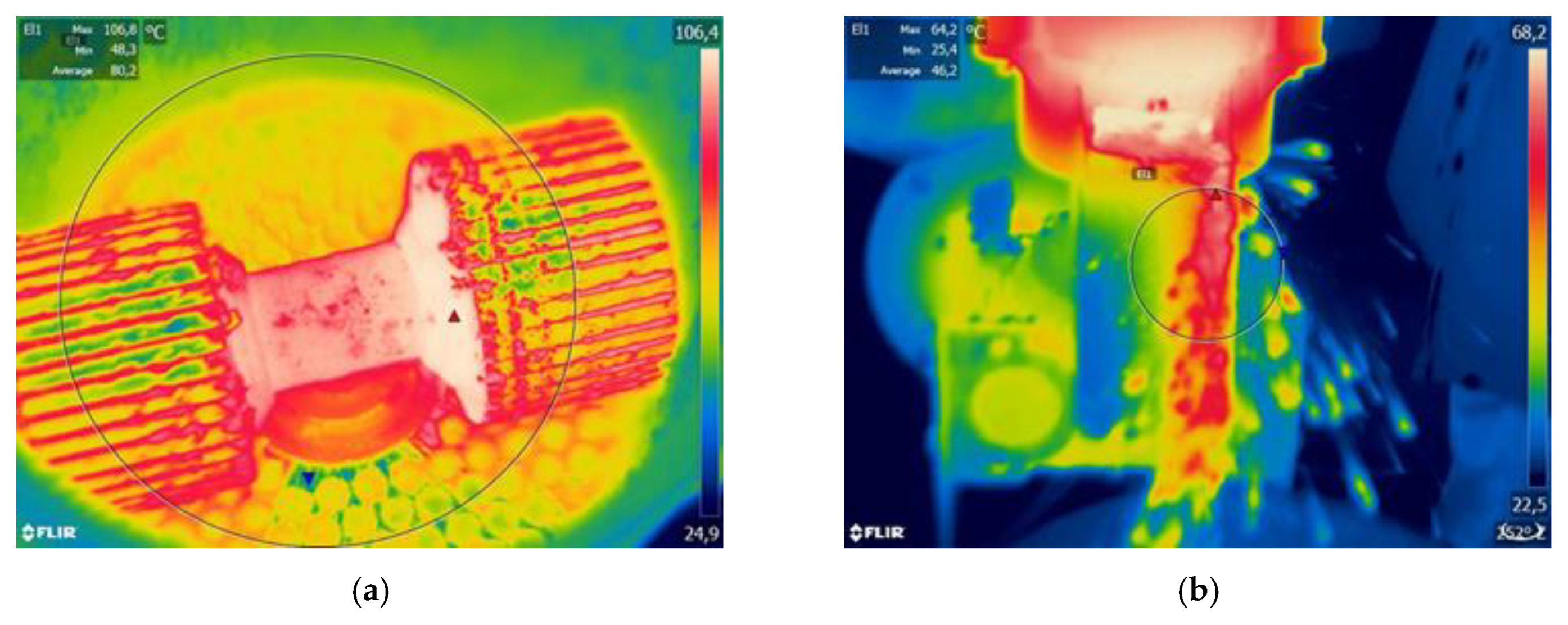
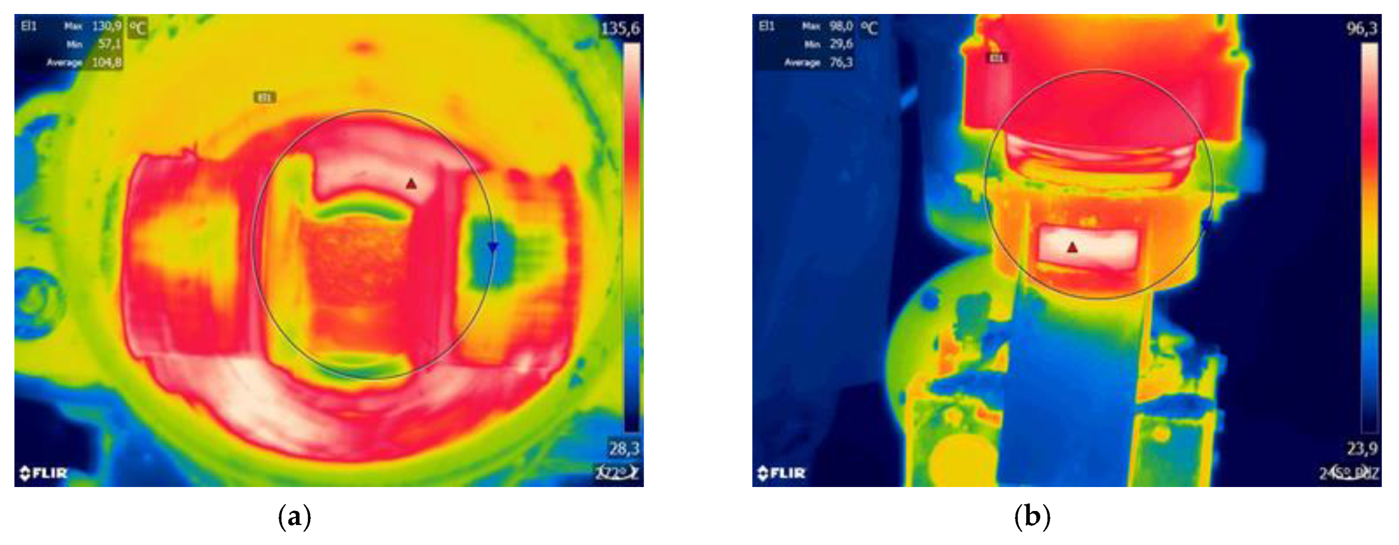
Before designing the new die, we tested the standard biomass die, to determine die temperature and pellet quality. We used a standard biomass die, with a channel diameter of 8 mm, a thickness of 35 mm, and an entry angle of 19.6°. The results, shown in Table 2, show that this type of channel geometry is inappropriate for RDF. Figure 13 shows images of pellets formed using this die. They are short and there are large amounts of fine particles. Thermographic analysis of the die and pellets temperatures are shown in Figure 14. For biomass material, the die temperature should be nearby 100°C [56,57]. For RDF, these temperatures are lower, reaching only 80 °C. This results in pellet temperatures at the 60 °C level. According to the laboratory-scale results, these values are too low. This was considered for the new die design.

Table 2.
Pellet quality and raw materials.
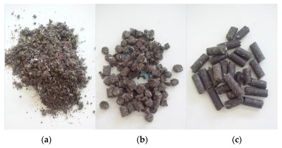
Figure 13.
(a) Images of the raw RDF grist, (b) pellets from biomass die, and (c) from modified RDF die.
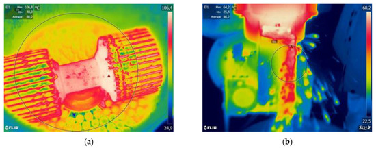
Figure 14.
Thermographs from the infrared (IR) camera using the biomass die: (a) view of die and rollers, and (b) view of pellet output.
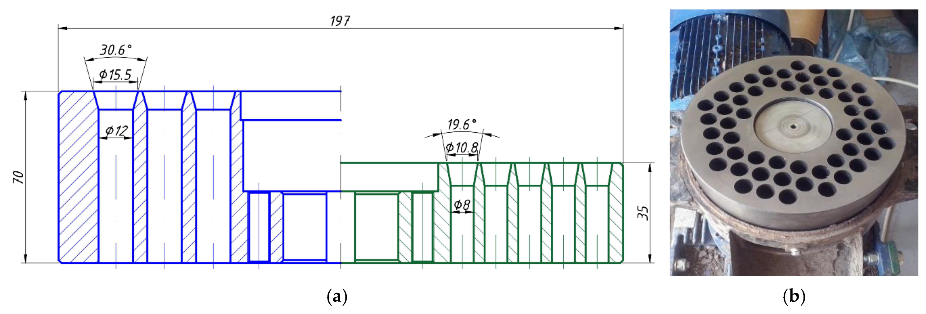
Details of the geometry, in comparison to biomass die, are shown in Figure 15a. Due to construction issues, we reduced the channel diameter to 12 mm (for details see the discussion section). The modified construction is also up to two times thicker (Figure 15b).
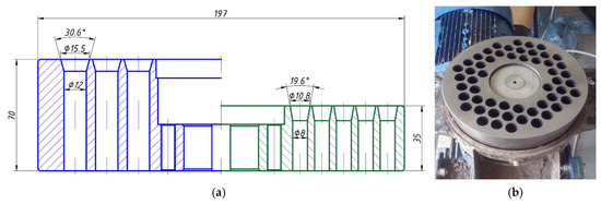
Figure 15.
(a) Modified die (blue) compared to standard biomass die (green), and (b) modified die mounted into the pelletiser.
3.4. Flat Die and Semi-Professional Line Results
The standard, used for biomass densification and redesigned for the RDF dies, was compared. From this test, we acquired information about bulk density and mechanical durability of the pellets. The results are presented in Table 1.
Thermographic analysis (with the IR camera) is shown Figure 16. It is clear that the die and pellet temperatures are higher. These increases meet assumptions made during the design process. In addition, Table 2 shows that based on a comparison of BD and DU for modified and standard dies to biomass, pellets from modified dies are of higher quality.
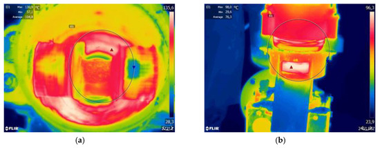
Figure 16.
Thermographs from IR camera while using the modified RDF die: (a) view of die and rollers, and (b) view of pellet output.
The final stage was verification of our design incorporated in other types of pelletisers (i.e., ring die), which are the most popular in high yield installations. The ring die was modified based on previous assumptions. Table 2 presents results from the semi-professional line equipped with a modified ring die. The bulk density and durability values confirm that produced pellets are of high quality.
4. Discussion
The results show how difficult RDF is, especially in terms of agglomeration. However, several aspects must be considered. First, there is the morphology of the waste stream. Composition can vary within the year, and it is dependent on many factors. This problem is described in many studies [2,17]. Based on the average composition, we could define parameters that can be tailored to materials like RDF. Low amount of binders in a pre-densified mixture in connection with high content of plastics requires special geometry. This will ensure a sufficiently high die temperature, exceeding 100°C. Such temperature for small scale production of pellets (laboratory scale) was not found in the literature [42,47].
A comparison of the specific density values leads to some issues connected with this material. In the laboratory-scale testing, it was difficult to form each sample with the same composition. This is the main reason there are such noticeable differences within a single series. As can be seen in Figure 10, some samples have many cracks, which reduces the measured density. In addition, there were some sections of hard and dense plastics (e.g., polyamide), so the granule density would be higher. Despite this, we were able to evaluate some general trends. The highest granule density was obtained with the smallest channel diameter: 16 mm. At this stage, it is difficult to determine why this dependency has occurred. The literature describes many density and pellet diameter analyses. In most cases, specific density depends on the type of material, although there is no clear dependency with pellet diameter [57].
The expansion factor provides information about the shape stability of pellets. Here, we specified that good quality pellets should not exceed an expansion coefficient greater than 10% (Figure 11). In this case, temperature plays a major role, as only a few granules exceeded the value of 5%. The averages for all diameters at this temperature were at a similar level (from 2.1% to 2.4%). The lowest expansion coefficient, occurring at the highest temperature could be explained by the melting of plastics on the outer surface of the granule. The produced shell then stabilises the shape. Slightly higher values, in the case of the 16 mm die, can be explained by the fact that all granules have similar mass. Thus, a small die diameter will result in higher quality pellets, and compressed material will act like a spring.
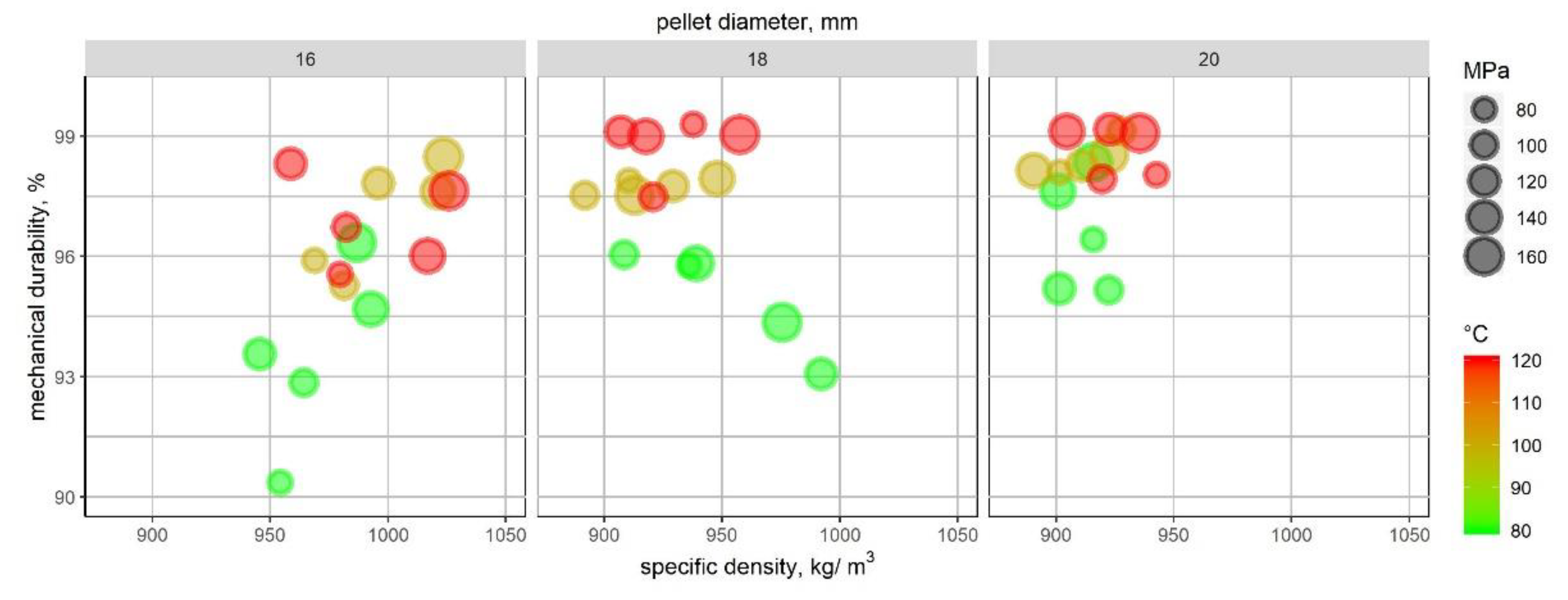
Given that the density of RDF-based pellets depends on composition, it is difficult to correlate this value with durability. For higher specific densities, higher durability is generally expected. For inhomogeneous material, such as MSW, this rule may not apply. Figure 17 shows that, in our case, these parameters do not correlate at all. Thus, this needs further investigation. More important is the earlier assumption that temperature plays a key role in pellet quality. This is confirmed in Figure 12. The durability of the pellets increases with temperature. For pellets of diameter 16 mm, we also observe a dependency with pressure. At 80 °C, durability is low, compared to other diameters. A similar problem occurs at higher temperatures. Higher temperature pellets have a tendency to break during the test, which should explain this phenomenon. Almost all samples at the temperature of 120 °C have a durability higher than 96%. This value is noted as a limit value for good quality biomass pellets [32]. It is hard to compare laboratory test results with pellets from real production, as we used a modification of the standardized method [53]. Nevertheless, this type of test seems to be more representative than the compressive strength analyses which can be often found in the literature [42,58,59,60]. The lower durability of the longer pellets can be explained in a different way. The closed chamber compaction has some limitations. The material, during densification, does not move with respect to the channel walls. The friction between the walls and materials is very low, and heat transfer is not very intense. Lower heating rates will result in less meltdown formation. Meltdowns form the plastic shell, which maintains the shape of the pellet. More heat transferred to pellet will result in a thicker shell. For long pellets, with a thin meltdown layer, the overall strength of the structure will be weaker. Thus, a thick meltdown layer or short pellets seems to be crucial for springy material like RDF.
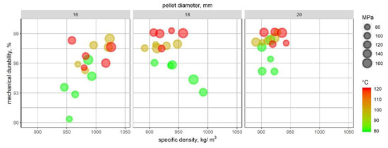
Figure 17.
The relationship between mechanical durability and specific density. Average values for series (five granules). Size represents compaction pressure and colours are in connection to temperature.
Considering all aspects from the laboratory-scale test, the RDF die should generate high temperatures and high compression. Higher expansion of the pellets, with smaller diameter, provides information on how to modify the geometry of the entry channel. For the biomass die, the entrance angle is usually about 20°. The conical section height is equal to, or higher than, the pellet diameter. This ensures good compression and arrangement of the particles. As a result, durable and long pellets will be produced. Different materials require modifications to the channel geometry. For RDF, this angle would be greater, as longer pellets will have greater expansion. To avoid forming long pellets, the conical section should be shorter than the channel diameter. This would result in the compaction of small portions of the material. Given that energy to heat up the die is generated from frictional forces, it was important to optimise this factor. The rollers moving on the die, and material squeezing through a channel, generates the most heat. Table 2 shows that under-heated die results in low-quality pellets. In addition, we do not observe meltdowns on the outer surface. This was one of the key conclusions from the laboratory-scale test. Therefore, in the prototype design, we decided to double the thickness of the die, increasing it to 70 mm. This would ensure that the material is exposed to high temperatures so that the meltdown of plastics occurs. It is clear the produced pellets show a different outer surface. For the biomass die, meltdowns do not occur, while the modified die produces a well-melted shell. This also improves the durability and bulk density of the pellets. This result confirms that temperature plays a major role in the pelletisation of the MSW-based materials. However, there are other crucial parameters to consider. Die geometry, especially the entry channel angle, is also important. Increasing this dimension generates good quality pellets. The die thickness also had a clear impact on durability. A longer residence time results in a thicker layer of molten plastics on the outer surface. This principle occurs with both the flat and ring die.
The comparison of bulk densities of the raw RDF and pellets gives clear information how this process affects fuel quality. Figure 18 shows that in case of RDF the BD of pellets can be up to five times higher in relation to raw material. At shown in literature [32,36,50,61,62] these values are achieved for soft biomass materials, with low bulk density. This will improve economics of transportation and logistics [36,50].

Figure 18.
Improvement in bulk densities (related to raw material) of RFD samples, in connection to literature, respectively [32,36,61].
5. Conclusions
This study aimed to determine the major factors that affect RDF-based pellet production. Our results show that RDF is a difficult material to work with. The key conclusions are as follows:
- Low bulk density of the raw RDF provides high potential in densification operations.
- Negligible content of natural binders enforces redesign of die.
- It was proven that temperature significantly affects pellet quality.
- The temperature condition of 120 °C results in the most durable pellets for all variations of compaction pressure and channel diameter. This is a result of the melting of plastics.
- Dies dedicated for RDF pelletisers should be thicker (double the thickness or more), compared to those for biomass pelletisers. This will ensure the formation of the outer shell from the melted plastics.
- Improvement in bulk density (by more up to five times), results in the reduction of transportation and storage costs.
Our results are relevant to many fields, which are not described in the literature. The majority of the tests undertaken on a small scale (when several pellets are formed), present compressive strength results. Such a test does not give information on how such material will behave during handling and other logistics processes. The modified method of determining mechanical durability proposed in the paper seems to be more representative than the compression strength test used in many analyses. However, it still needs to be analysed in detail, and this will be done in the near future. Additionally, further research on channel dimensions may be useful for improving this topic. This will require the design of a new type of laboratory-scale attachment, which should enable analysis on the influence of both the entry angle and channel length on pellet quality. A similar device is presented in the literature [63].
Author Contributions
Conceptualization, K.M., M.W., and J.F.; methodology, K.M., M.W., J.F.; investigation, K.M., M.W., M.J., and K.D.; resources, M.J. and K.D; data curation, M.J. and M.W.; writing—original draft preparation, M.J. and K.D.; writing—review and editing, M.J.; visualization, M.J.; supervision, J.F., K.M., and M.W. All authors have read and agreed to the published version of the manuscript.
Funding
This study was founded as part of grant “EkoRDF—an innovative manufacturing technology of alternative fuel from municipal waste for power and heating plants—a key component of the Polish waste management system” financed by the Polish Centre for Research and Development (GEKON programme), which was undertaken at the University of Agriculture in Kraków. Grant no GEKON2/05/268002/17/2015.
Acknowledgments
The authors express many thanks to Wiktor Głowa, MSc, who performed part of the laboratory tests.
Conflicts of Interest
The authors declare no conflict of interest.
References
- European Commission. Life Cycle Thinking and Assessment for Waste Management; European Commission: Brussels, Belgium, 2016. [Google Scholar]
- Jewiarz, M.; Frączek, J.; Mudryk, K.; Wróbel, M.; Dziedzic, K. Analysis of MSW Potential in Terms of Processing into Granulated Fuels for Power Generation. In Renewable Energy Sources: Engineering, Technology, Innovation; Springer: Cham, Switzerland, 2018; pp. 661–670. [Google Scholar]
- Caputo, A.C.; Palumbo, M.; Scacchia, F. Perspectives of RDF use in decentralized areas: Comparing power and co-generation solutions. Appl. Therm. Eng. 2004, 24, 2171–2187. [Google Scholar] [CrossRef]
- Caputo, A.C.; Pelagagge, P.M. RDF production plants: II. Economics and profitability. Appl. Therm. Eng. 2002, 22, 439–448. [Google Scholar] [CrossRef]
- Białowiec, A.; Micuda, M.; Koziel, J.A. Waste to Carbon: Densification of Torrefied Refuse-Derived Fuel. Energies 2018, 11, 3233. [Google Scholar] [CrossRef]
- Rahman, A.; Rasul, M.G.; Khan, M.M.K.; Sharma, S.C. Assessment of energy performance and emission control using alternative fuels in cement industry through a process model. Energies 2017, 10, 1996. [Google Scholar] [CrossRef]
- Hemidat, S.; Saidan, M.; Al-Zu’bi, S.; Irshidat, M.; Nassour, A.; Nelles, M. Potential utilization of RDF as an alternative fuel to be used in cement industry in Jordan. Sustainability 2019, 11, 5819. [Google Scholar] [CrossRef]
- Grzesik, K.; Malinowski, M. Life cycle assessment of refuse-derived fuel production from mixed municipal waste. Energy Sources Part A Recover. Util. Environ. Eff. 2016, 38, 3150–3157. [Google Scholar] [CrossRef]
- Nickolaos, C. Use of waste derived fuels in cement industry: A review. Manag. Environ. Qual. Int. J. 2016, 27, 178–193. [Google Scholar]
- Ryu, C.; Shin, D. Combined heat and power from municipal solid waste: Current status and issues in South Korea. Energies 2013, 6, 45–57. [Google Scholar] [CrossRef]
- Lupa, C.J.; Ricketts, L.J.; Sweetman, A.; Herbert, B.M.J. The use of commercial and industrial waste in energy recovery systems—A UK preliminary study. Waste Manag. 2011, 31, 1759–1764. [Google Scholar] [CrossRef]
- Sever Akdağ, A.; Atimtay, A.; Sanin, F.D. Comparison of fuel value and combustion characteristics of two different RDF samples. Waste Manag. 2016, 47, 217–224. [Google Scholar] [CrossRef]
- Dziedzic, K.; Łapczyńska-Kordon, B.; Malinowski, M.; Niemiec, M.; Sikora, J. Impact of Aerobic Biostabilisation and Biodrying Process of Municipal Solid Waste on Minimisation of Waste Deposited in Landfills. Chem. Process Eng. 2015, 36, 381–394. [Google Scholar] [CrossRef][Green Version]
- Debicka, M.; Zygadło, M.; Latosinska, J. Investigations of bio-drying process of municipal solid waste. Ecol. Chem. Eng. A 2013, 20, 1461–1470. [Google Scholar]
- Waste Hierarchy. Available online: https://en.wikipedia.org/wiki/Waste_hierarchy (accessed on 28 January 2020).
- EWIT. The Waste Hierarchy—Hazardous Waste in a Circular Economy. Available online: http://ewit.site/kb/waste-hierarchy-hazardous-waste-circular-economy/ (accessed on 28 January 2020).
- Młodnicki, K.; Malinowski, M.; Łukasiewicz, M.; Religa, A. The share of impurities in selectively collected waste in one- and multi-sack systems. Ecol. Chem. Eng. A 2018, 25, 187. [Google Scholar]
- Petryk, A.; Malinowski, M.; Dziewulska, M.; Guzdek, S. The impact of the amount of fees for the collection and management of municipal waste on the percentage of selectively collected waste. J. Ecol. Eng. 2019, 20, 46–53. [Google Scholar] [CrossRef]
- Malinowski, M.; Łukasiewicz, M.; Famielec, S.; Nowińska, K. Analysis of changes in fees for the collection and management of municipal waste as regards the efficiency of waste segregation. Ekon. Sr. 2019, 69, 24–41. [Google Scholar]
- Wróbel, M.; Frączek, J.; Mudryk, K.; Jewiarz, M.; Dziedzic, K. Conceptual Design of the RDF Granulation Line. In Renewable Energy Sources: Engineering, Technology, Innovation; Springer: Cham, Switzerland, 2018; pp. 813–821. [Google Scholar]
- Wrobel, M.; Mudryk, K.; Jewiarz, M.; Knapczyk, A. Impact of raw material properties and agglomeration pressure on selected parmeters of granulates obtained from willow and black locust biomass. Eng. Rural Dev. 2018, 17, 1933–1938. [Google Scholar]
- Knapczyk, A.; Francik, S.; Wrobel, M.; Mudryk, K. Comparison of selected agriculture universities in Europe on basis of analysis of academic output. In Proceedings of the 17th International Scientific Conference Engineering for Rural Development, Jelgava, Latvia, 23–25 May 2018; pp. 727–732. [Google Scholar]
- Lockwood, F.C.; Ou, J.J. Review: Burning Refuse-Derived Fuel in a Rotary Cement Kiln. Proc. Inst. Mech. Eng. Part A J. Power Energy 1993, 207, 65–70. [Google Scholar] [CrossRef]
- Del Zotto, L.; Tallini, A.; Di Simone, G.; Molinari, G.; Cedola, L. Energy enhancement of Solid Recovered Fuel within systems of conventional thermal power generation. Energy Procedia 2015, 81, 319–338. [Google Scholar] [CrossRef]
- Nixon, J.D.; Dey, P.K.; Ghosh, S.K.; Davies, P.A. Evaluation of options for energy recovery from municipal solid waste in India using the hierarchical analytical network process. Energy 2013, 59, 215–223. [Google Scholar] [CrossRef]
- Zhou, L.; Luo, T.; Huang, Q. Co-pyrolysis characteristics and kinetics of coal and plastic blends. Energy Convers. Manag. 2009, 50, 705–710. [Google Scholar] [CrossRef]
- Chen, D.; Yin, L.; Wang, H.; He, P. Pyrolysis technologies for municipal solid waste: A review. Waste Manag. 2014, 34, 2466–2486. [Google Scholar] [CrossRef] [PubMed]
- Białowiec, A.; Pulka, J.; Stępień, P.; Manczarski, P.; Gołaszewski, J.; Adefeso, I.B.; Ikhu-Omoregbe, D.I.O.; Rabiu, A.M. Sustainable co-generation plant: Refuse-derived fuel gasification integrated with high temperature PEM fuel cell system. Waste Manag. 2013, 70, 91–100. [Google Scholar] [CrossRef]
- Whittaker, C.; Shield, I. Factors affecting wood, energy grass and straw pellet durability—A review. Renew. Sustain. Energy Rev. 2017, 71, 1–11. [Google Scholar] [CrossRef]
- Antczak, A.; Michaluszko, A.; Klosinska, T.; Drozdzek, M. Determination of the structural substances content in the field maple wood (Acer campestre L.)—Comparsion of the classical methods with instrumental. Ann. Warsaw Univ. Life Sci.-SGGW. For. Wood Technol. 2013, 82, 11–17. [Google Scholar]
- Tishler, Y.; Samach, A.; Rogachev, I.; Elbaum, R.; Levy, A.A. Analysis of Wheat Straw Biodiversity for Use as a Feedstock for Biofuel Production. Bioenergy Res. 2015, 8, 1831–1839. [Google Scholar] [CrossRef]
- Peter, K. The Densification Process of Wood Waste; De Gruyter: Berlin, Germany, 2015; ISBN 978-3-11-044142-0. [Google Scholar]
- Stelte, W.; Holm, J.K.; Sanadi, A.R.; Barsberg, S.; Ahrenfeldt, J.; Henriksen, U.B. A study of bonding and failure mechanisms in fuel pellets from different biomass resources. Biomass Bioenergy 2011, 35, 910–918. [Google Scholar] [CrossRef]
- Finney, K.N.; Sharifi, V.N.; Swithenbank, J. Fuel pelletization with a binder: Part I—Identification of a suitable binder for spent mushroom compost—Coal tailing pellets. Energy Fuels 2009, 23, 3195–3202. [Google Scholar] [CrossRef]
- Jamradloedluk, J.; Lertsatitthanakorn, C. Influences of Mixing Ratios and Binder Types on Properties of Biomass Pellets. Energy Procedia 2017, 138, 1147–1152. [Google Scholar] [CrossRef]
- Van Loo, S.; Koppejan, J. The Handbook of Biomass Combustion and Co-firing; Taylor & Francis Group: Abingdon, UK, 2012; ISBN 9781849773041. [Google Scholar]
- Wrobel, M.; Fraczek, J.; Francik, S.; Slipek, Z.; Krzysztof, M. Influence of degree of fragmentation on chosen quality parameters of briquette made from biomass of cup plant Silphium perfoliatum L. In Proceedings of the 12th International Scientific Conference on Engineering for Rural Development, Jelgava, Latvia, 23–24 May 2013; 2013; pp. 653–657. [Google Scholar]
- Mudryk, K.; Fraczek, J.; Slipek, Z.; Francik, S.; Wrobel, M. Chosen physico-mechanical properties of cutleaf coneflower (Rudbeckia Laciniata l.) shoots. In Proceedings of the 12th International Scientific Conference on Engineering for Rural Development, Jelgava, Latvia, 23–24 May 2013; pp. 658–662. [Google Scholar]
- Wróbel, M. Zagęszczalność i Kompaktowalność Biomasy Lignocelulozowej; PTIR: Kraków, Poland, 2019; ISBN 978-83-64377-35-8. [Google Scholar]
- Payne, J.D. Troubleshooting the Pelleting Process; American Soybean Association: St. Louis, MO, USA, 1997. [Google Scholar]
- Holm, J.K.; Stelte, W.; Posselt, D.; Ahrenfeldt, J.; Henriksen, U.B. Optimization of a Multiparameter Model for Biomass Pelletization to Investigate Temperature Dependence and to Facilitate Fast Testing of Pelletization Behavior. Energy Fuels 2011, 25, 3706–3711. [Google Scholar] [CrossRef]
- Sprenger, C.J.; Tabil, L.G.; Soleimani, M.; Agnew, J.; Harrison, A. Pelletization of Refuse-Derived Fuel Fluff to Produce High Quality Feedstock. J. Energy Resour. Technol. 2018, 140, 042003. [Google Scholar] [CrossRef]
- Sarc, R.; Lorber, K.E. Production, quality and quality assurance of Refuse Derived Fuels (RDFs). Waste Manag. 2013, 33, 1825–1834. [Google Scholar] [CrossRef] [PubMed]
- Knapczyk, A.; Francik, S.; Fraczek, J.; Slipek, Z. Analysis of research trends in production of solid biofuels. Eng. Rural Dev. 2019, 18, 1503–1509. [Google Scholar]
- Dyjakon, A.; Noszczyk, T. The influence of freezing temperature storage on the mechanical durability of commercial pellets from biomass. Energies 2019, 12, 2627. [Google Scholar] [CrossRef]
- Civitarese, V.; Acampora, A.; Sperandio, G.; Assirelli, A.; Picchio, R. Production of wood pellets from poplar trees managed as coppices with Different harvesting cycles. Energies 2019, 12, 2973. [Google Scholar] [CrossRef]
- Sprenger, C.; Tabil, L.G.; Soleimani, M. Compression and relaxation properties of municipal solid waste refuse-derived fuel fluff. KONA Powder Part. J. 2018, 2018, 200–208. [Google Scholar] [CrossRef]
- Nielsen, N.P.K.; Holm, J.K.; Felby, C. Effect of Fiber Orientation on Compression and Frictional Properties of Sawdust Particles in Fuel Pellet Production. Energy & Fuels 2009, 23, 3211–3216. [Google Scholar]
- Karbowniczak, A.; Hamerska, J.; Wrobel, M.; Jewiarz, M.; Necka, K. Evaluation of Selected Species of Woody Plants in Terms of Suitability for Energy Production. In Springer Proceedings in Energy; Springer International Publishing: Cham, Switzerland, 2018; pp. 735–742. [Google Scholar]
- Thek, G.; Obernberger, I. The Pellet Handbook: The Production and Thermal Utilization of Biomass Pellets; Taylor & Francis: Abingdon, UK, 2012; ISBN 9781136539916. [Google Scholar]
- Shaw, M.D.; Tabil, L.G. Compression and Relaxation Characteristics of Selected Biomassgrinds. In 2007 ASAE Annual Meeting; American Society of Agricultural and Biological Engineers: St. Joseph, MI, USA, 2007. [Google Scholar]
- Kachel, M.; Kraszkiewicz, A.; Subr, A.; Parafiniuk, S.; Przywara, A.; Koszel, M.; Zając, G. Impact of the Type of Fertilization and the Addition of Glycerol on the Quality of Spring Rape Straw Pellets. Energies 2020, 13, 819. [Google Scholar] [CrossRef]
- International Organization for Standardization. ISO 17831-1:2015 Solid Biofuels—Determination of Mechanical Durability of Pellets and Briquettes—Part 1: Pellets; International Organization for Standardization: Geneva, Switzerland, 2015. [Google Scholar]
- Larsson, S.H.; Samuelsson, R. Prediction of ISO 17831-1:2015 mechanical biofuel pellet durability from single pellet characterization. Fuel Process. Technol. 2017, 163, 8–15. [Google Scholar] [CrossRef]
- International Organization for Standardization. ISO 17828:2015 Solid Biofuels—Determination of Bulk Density; International Organization for Standardization: Geneva, Switzerland, 2015. [Google Scholar]
- Mostafa, M.E.; Hu, S.; Wang, Y.; Su, S.; Hu, X.; Elsayed, S.A.; Xiang, J. The significance of pelletization operating conditions: An analysis of physical and mechanical characteristics as well as energy consumption of biomass pellets. Renew. Sustain. Energy Rev. 2019, 105, 332–348. [Google Scholar] [CrossRef]
- Tumuluru, J.S. Effect of process variables on the density and durability of the pellets made from high moisture corn stover. Biosyst. Eng. 2014, 119, 44–57. [Google Scholar] [CrossRef]
- Kambo, H.S.; Dutta, A. Strength, storage, and combustion characteristics of densified lignocellulosic biomass produced via torrefaction and hydrothermal carbonization. Appl. Energy 2014, 135, 182–191. [Google Scholar] [CrossRef]
- Carone, M.T.; Pantaleo, A.; Pellerano, A. Influence of process parameters and biomass characteristics on the durability of pellets from the pruning residues of Olea europaea L. Biomass Bioenergy 2011, 35, 402–410. [Google Scholar] [CrossRef]
- Jiang, L.; Liang, J.; Yuan, X.; Li, H.; Li, C.; Xiao, Z.; Huang, H.; Wang, H.; Zeng, G. Co-pelletization of sewage sludge and biomass: The density and hardness of pellet. Bioresour. Technol. 2014, 166, 435–443. [Google Scholar] [CrossRef] [PubMed]
- Theerarattananoon, K.; Xu, F.; Wilson, J.; Ballard, R.; Mckinney, L.; Staggenborg, S.; Vadlani, P.; Pei, Z.J.; Wang, D. Physical properties of pellets made from sorghum stalk, corn stover, wheat straw, and big bluestem. Ind. Crops Prod. 2011, 33, 325–332. [Google Scholar] [CrossRef]
- Monedero, E.; Portero, H.; Lapuerta, M. Pellet blends of poplar and pine sawdust: Effects of material composition, additive, moisture content and compression die on pellet quality. Fuel Process. Technol. 2015, 132, 15–23. [Google Scholar] [CrossRef]
- Lisowski, A.; Olendzki, D.; Świętochowski, A.; Dąbrowska, M.; Mieszkalski, L.; Ostrowska-Ligęza, E.; Stasiak, M.; Klonowski, J.; Piątek, M. Spent coffee grounds compaction process: Its effects on the strength properties of biofuel pellets. Renew. Energy 2019, 142, 173–183. [Google Scholar] [CrossRef]
© 2020 by the authors. Licensee MDPI, Basel, Switzerland. This article is an open access article distributed under the terms and conditions of the Creative Commons Attribution (CC BY) license (http://creativecommons.org/licenses/by/4.0/).

