Abstract
The subsea tree is one of the critical pieces of equipment in the subsea production system, and its installation is related to the safe production of offshore oil and gas. Due to the differences in the form of the structures, the speed of entering the water, the marine environment, and other factors, the process of the structure entering the water is exceedingly complicated. During the engineering installation, the most dangerous phase involves the structure passing through the splash zone. Based on the theory of the movement of the subsea tree passing through the splash zone, Lingshui 17-2 subsea tree installation was analyzed with the marine engineering software OrcaFlex, and a sensitivity analysis of the lowering of the subsea tree was performed. During the splash zone phase, the wave height had the highest impact on the subsea tree, affecting the horizontal offset and cable load, which may lead to the oil tree capsizing and cable breakage. Furthermore, the velocity only affected the horizontal offset, and the overall effect was not noticeable. The operational safety window for the subsea tree installation was established according to the operational safety standards. Therefore, the recommended lowering speed was 0.50 m/s, while the flow velocity should not exceed 1.50 m/s, and the wave height should not be higher than 4.5 m.
1. Introduction
A subsea production system is an essential component in offshore platform installation. Subsea production systems are mainly composed of subsea trees, subsea manifolds, subsea well control systems, and subsea processing systems [1,2]. Forming the core of the subsea production system is the subsea tree, the primary function of which is to control the flow of produced oil and gas, monitor oil and gas parameters, as well as form an isolation barrier between the underground reservoir and the environment containing the subsea wellhead system [3]. The submarine environment is relatively safe compared to the sea surface, but the installation of the subsea trees is more complicated.
According to the China Classification Society (CCS) fixed platform specifications, the splash zone refers to the area where the seawater rises and falls periodically due to the action of waves, that is, the wave height in this area [4]. As shown in Figure 1, the installation of a subsea tree generally goes through three stages, where the subsea tree passes through the splash zone, continues to be decentralized, and is lowered to the designated position. The subsea tree passing through the splash zone denotes the process of entering the water from the air, which is the most dangerous stage of the installation procedure and is generally an exceedingly slow operation. When the subsea tree is lowered, the waves of the ocean rise and fall, generating relative speed between the seawater and the subsea tree, generating an interaction force when the two make contact with each other. When the subsea tree enters the water, it generates an additional impact force, affecting the stability of the subsea tree. Improper operation may cause the subsea tree to overturn or be damaged by the assault of the water at the bottom, potentially causing engineering accidents.
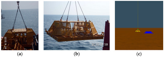
Figure 1.
The subsea tree passing through the splash zone (from left to right): (a) Pass through the splash zone, (b) Continue decentralization, (c) Lower to the designated position.
It is technically challenging for the subsea tree to pass through the splash zone [5]. Therefore, to ensure that the installation process is completed safely and efficiently, it is necessary to carry out appropriate simulations and careful calculations before installation to determine the installation safety window, evaluate possible accident risk factors, and formulate corresponding emergency rescue plans. Rhee et al. [6] and Howison et al. [7] stated that when the structure entered the water, the water surface became a free liquid surface. The effect of air had little effect on the final result, but they noticed that the structure was subjected to uneven forces during the water ingress. In terms of test methods, Cui et al. [8] and Hao et al. [9] studied the influence of different rods and different conditions on the process of entering the water. Since the 21st century, scholars have focused their research on wedges entering the water. Carcaterra et al. [10], Yettou et al. [11], Tveitnes et al. [12], and Tian et al. [13] assessed water ingress at different angles and speeds to obtain wedges, and their results regarding surface pressure and angle when entering the water corresponded with each other. Regarding numerical calculation, Fraenkel et al. [14] and Oger et al. [15] summarized the previous theory and derived a numerical solution for the problem involving a two-dimensional axisymmetric structure entering the water, while Moore et al. [16], Facci et al. [17], and Takagi [18] extended the two-dimensional structure to one that was three-dimensional. Furthermore, it was believed that the above method for calculating the maximum impact hydrodynamic pressure of the wedge into the water was higher than the actual pressure. Shi et al. [19], Jiang et al. [20], and Shen [21] used numerical algorithms to simulate and analyze the change law of impact load under different shapes, speed of entry, and angle of entry.
In the past, research involving structural installation and decentralization has mainly focused on the force of different object shapes at different water inflow speeds and angles. However, few studies exist involving the marine environment, such as current speed, wave height, and the stability of the subsea tree installation. Guan [22] studied wave impacts on structures in the splash zone by using a simplified one-dimensional numerical model. Jia and Agrawal [23] proposed a coupled fluid-structure interaction (FSI) approach to predict wave induced motions, wave loads, dynamic stresses, and deformation of subsea structure and equipment in the splash zone during installation. Du et al. [24] used the explicit formulation dynamic analysis finite element to predict the wave slamming forces on the subsea equipment bottom panels in the splash zone during installation. Nam et al. [25] presented an experimental study of the deepwater lifting and lowering operations of a subsea manifold, and regular wave tests were carried out to investigate the vessel motion and wire tension responses during the deepwater lifting operation. El Mouhandiz et al. [26] studied the hoist wire dynamics and lowering speeds of the subsea structure installation while passing through the splash zone. Previous studies mostly focused on the influence of a single factor on the subsea tree passing through the splash zone, and no safety window for engineering applications was developed for engineering applications. In this paper, taking Lingshui 17-2 actual engineering project as an example, the engineering ship, subsea tree, and its installation tools are modeled, the influence of multiple marine environments is considered, and the multi-body movement relationship between the engineering ship and the lowered structure is established. The effects of velocity, wave height, period, and lowering speed on the installation of the subsea tree is analyzed, the safety window is established to guide the installation of the subsea tree.
2. Installation Theory of the Subsea Tree Passed Through the Splash Zone
When the subsea tree passes through the splash zone, the deformation of the free water surface is considered. Air is a compressible gas, which satisfies the ideal gas state equation. The water is not viscous and incompressible. It was assumed here that the length of the subsea tree is l, and the install speed is V(t). The theoretical model of the subsea tree into water is shown in Figure 2.
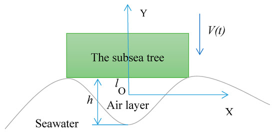
Figure 2.
Theoretical model of the subsea tree into water.
In the process of entering the water, since the two are in surface contact, the phenomenon of compressed air will occur. The air is squeezed by both solid and liquid, and the middle air will escape to both sides. When the solid-liquid contact is close enough, the relative flat-bottom width is sufficiently small, that is, when h/l ≤ 1 is satisfied, the movement of the air sandwiched between the two can be regarded as flowing along the x-axis direction, regardless of the air viscosity. The equations of motion and continuity are obtained as follows:
In Equations (1) and (2), u is the moving speed of the air layer in the horizontal direction, p is the pressure of air, ρa is the density of air, and h is the thickness of the air layer.
In the process of entering the water, the air is continuously squeezed by both solid and liquid states, and the intermediate air will continue to escape to both sides. When the solid and liquid come into contact, some air will still be exhausted in the future, which forms an air cushion, and the process of compressing air can be expressed by the following equation of state:
In Equation (3), γ represents the specific heat ratio of air, and p0 and ρ0 correspond to the air pressure and density in the initial state, respectively.
Assuming the initial time t = 0, h (x, t) = h0, V (t) = V0, and η (x, t) represent the height of the free water surface, then the distance between the subsea tree and the water surface can be expressed as:
Further analyzing Equation (4), the relationship between the thickness of the air cushion and the height of the water surface can be expressed as:
By analyzing the movement process and combining the momentum theorem, we can obtain the speed change equation of the subsea tree under the action of gravity and the reaction of compressed air:
In Equation (5), Ms represents the quality of the subsea tree.
When passing through the splash zone, the ship, cable, and the subsea tree form a multi-body motion system that interact with each other. After the subsea tree enters the water, it has six degrees of freedom in the water, which is simplified to a two-dimensional plane motion. The force diagram of the subsea tree is shown in Figure 3.
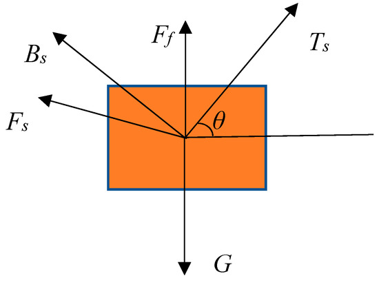
Figure 3.
The force diagram of the subsea tree.
According to Newton’s second law:
where is the cable tension, is the buoyancy of the subsea tree, is the fluid resistance experienced by the subsea tree, is the additional mass force of the subsea tree, and is the gravity of the subsea tree.
Along the cable:
Perpendicular to the cable:
The bottom end of the cable is connected to the subsea tree. In the horizontal direction:
In the vertical direction:
In the above Equations, v is the vertical speed of the ship crane, φ is the speed of the lowering rope, l is the length of the lowering rope, and θ is the angle between the rope and the horizontal direction.
The theoretical calculations shown above are the basic theory of the subsea tree entering the water. It mainly analyzes the movement and force of the subsea tree when it passes through the splash zone. However, due to the complexity of the problem of the subsea tree passing through the splash zone, the current theory cannot accurately give the calculation. To solve the problem, simulation software is needed to calculate the entering conditions of the subsea tree.
3. Analysis of the Subsea Tree Passing Through the Splash Zone
3.1. System Modeling
3.1.1. System Parameter
This paper used the Lingshui 17-2 gas field project in the South China Sea as a case for installation research. According to the actual sea conditions, the density of the seawater is 1.025 × 10³ kg/m3, and the kinematic viscosity coefficient is 1.35 × 10⁻⁶ m2/s, while the temperature is shown in Figure 4. The current parameters are shown in Table 1, and the wave parameters are shown in Table 2.
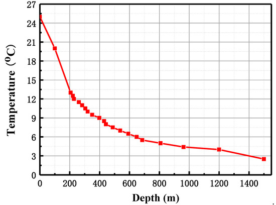
Figure 4.
Seawater temperature graph.

Table 1.
Current parameters.
Table 2.
Wave parameters.
3.1.2. Model Establishment
A steel wire rope with a diameter of 4 inches was used for the installation, where one end of the rope was connected to the subsea tree, and an anti-rotational mechanism was installed to prevent the subsea tree from rotating during the installation process, and affecting the installation and positioning.
Given the conditions of the South China Sea Lingshui 17-2 area, Offshore Oil 708 was selected as the installation vessel. The parameters of Offshore Oil 708 are shown in Table 3, the physical parameters of the subsea tree and the installation tool are shown in Table 4, while the subsea tree and the installation tool material parameters are shown in Table 5. In the OrcaFlex software, the 6D buoy model was used to model the subsea tree and its installation tool. Based on geometric similarity and kinematic similarity, the subsea tree was simplified, while the overall structure of the tree remained unchanged. Masses such as pipes and joints were assigned to the body of the tree, ensuring that the center of gravity of the simplified model remained unchanged. The structures of components such as the tree valve and tree frame were modeled with an elastic solid, and the installation tool was connected to the subsea tree. Figure 5 shows the 3D model of the installation vessel, the subsea tree and installation tool generated with the OrcaFlex software.
Table 3.
Engineering ship parameters.
Table 4.
The subsea tree and installation tool parameters.
Table 5.
The subsea tree and installation tool material parameters.
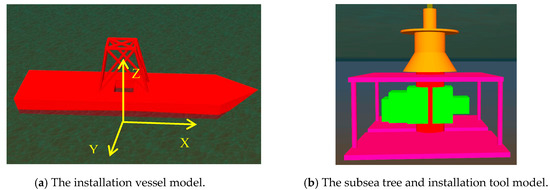
Figure 5.
The installation vessel, the subsea tree, and installation tool 3D model.
After the modeling work was completed, the parameters were set according to the actual working conditions, after which environmental loads were applied, and the installation process of the structure through the splash zone was analyzed. The safe lowering standards provided in the Ocean Engineering Technical Guide and listed in Table 6 were followed before carrying out the hoisting installation [27]. Horizontal movement included the X offset and Y offset, while the vertical movement referred to the Z offset.
Table 6.
Safety standard.
3.2. Simulation Analysis of the Subsea Tree Passing Through the Splash Zone
3.2.1. Analysis of Different Velocities
When passing through the splash zone, the wave velocity and period under normal weather conditions were considered as invariant, which in this case denoted a wave height of 1.5 m and a period of 7 s, while the velocity was taken as 0 m/s, 0.50 m/s, 1.07 m/s, and 1.50 m/s. Then, the horizontal X offset, Y offset, vertical Z offset, and the cable stress of the subsea tree were analyzed. The simulation analysis results are shown in Figure 6.
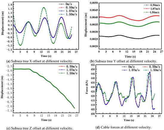
Figure 6.
Subsea Tree offset and cable forces at different velocity.
Figure 6a shows that when the wave height was 1.5 m and the velocity changed within 1.07 m/s, the X offset of the subsea tree was not affected by the velocity, while the offset of the subsea tree remained the same. At a wave height of 1.5 m and a velocity of 1.50 m/s, the displacement of the subsea tree exceeded 1.5 m. Therefore, according to the safety standards listed in Table 6, these weather conditions were no longer suitable to continue work. Figure 6b indicates that the velocity offset for the Y-direction of the subsea tree into the water was within 0.0034 m, while the velocity offset was negligible. Figure 6c illustrates that different flow conditions induced no change in the displacement of the subsea tree in the Z-direction. Furthermore, the results showed that the velocity did not affect the displacement of the subsea tree during vertical movement. Figure 6d shows that at a wave height of 1.5 m and a flow velocity of 1.50 m/s, the cable force fluctuated significantly, indicating that these weather conditions were no longer suitable to continue work. When the wave height was 1.5 m and the velocity changed within a range of 0–1.07 m/s, the cable force was relatively stable and the changes remained the same.
When the subsea tree was lowered to a depth of 10 m, which is out of the splash zone, the set environmental parameters were consistent with the previous ones, and the simulation analysis results shown in Figure 7 were obtained.
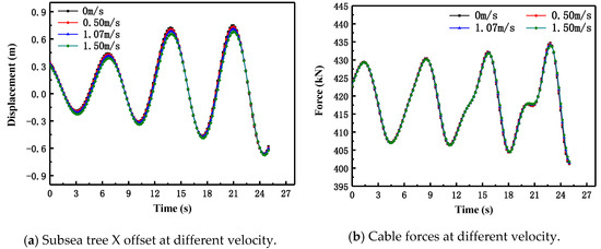
Figure 7.
Subsea tree offset and cable forces at different velocity.
Figure 7a shows that at a depth of 10 m, a velocity of 0–1.50 m/s had little effect on the displacement of the subsea tree, while the offset of the subsea tree was below 0.75 m, which met the requirement specification for safe operation. Compared with Figure 6a, it is clear that the splash area substantially influenced the offset, which decreased as the water depth increased after passing through the splash area. Furthermore, Figure 7b indicates that the maximum force of the cable was 435 kN at a velocity of 1.50 m/s, while the fluctuation remained stable, indicating that the current responsible for restricting proper functioning of the subsea tree was mainly located in the splash zone. When the subsea tree was out of the splash zone, the current had little effect on the offset and cable force.
3.2.2. Analysis of Different Wave Heights
When passing through the splash zone, the wave velocity and period under normal weather conditions were considered invariant, which in this case denoted a velocity is 0.50 m/s and a period of 7 s. The wave heights were taken as 0 m, 1.51 m, 3.03 m, and 4.50 m, while the lateral X offset and cable stress of the subsea tree were analyzed. The simulation analysis results are shown in Figure 8.
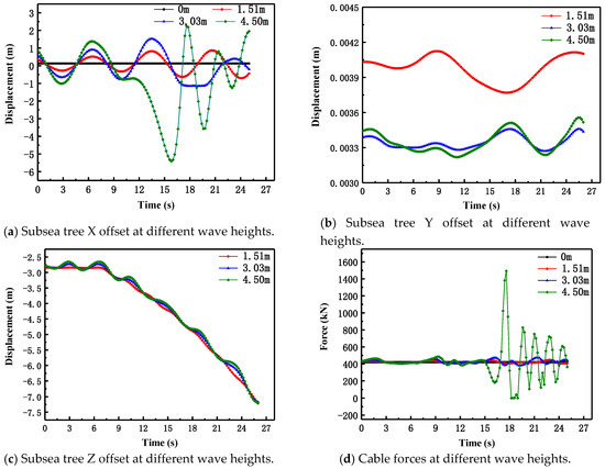
Figure 8.
Subsea tree offset and cable forces at different wave heights.
Figure 8a shows that at a velocity of 0.50 m/s and a wave height of 3.03 m, the displacement of the subsea tree was close to 1.5 m. At a velocity of 0.50 m/s and a wave height of 4.50 m, the subsea tree displacement was 5.5 m. Compared to Figure 8d, the force of the cable increased sharply, with the maximum value reaching 1500 kN. Since the cable is not pressure-resistant, the slackening of the cable may cause the subsea tree to overturn. This event would be followed by the cable being tensioned again and withstanding a relatively large impact tensile force, which would cause a certain degree of damage or even weaken the strength of the cable, rendering it unsuitable to be employed during installation. Figure 8b indicates that the Y-direction offset was within 0.0042 m, while the wave height was negligible for the Y-direction offset. Figure 8c shows that although the wave height influenced the Z-direction migration of the subsea tree, this impact was minimal. Therefore, a larger wave height value induced a more significant variation in the Z-direction offset fluctuation value.
When the subsea tree was lowered to a depth of 10 m, the set environmental parameters were consistent with those previously established, obtaining the simulation analysis results shown in Figure 9.
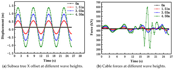
Figure 9.
Subsea tree offset and cable forces at different wave heights.
When a water depth of 10 m was reached, the displacement of the tree increased steadily in conjunction with an increase in the wave height. The overall offset value was smaller than when the subsea tree just entered the water. When it was set to 4.50 m, a substantial force change was evident in the cable, while the maximum force was 650 kN.
3.2.3. Analysis of Different Periods
When passing through the splash zone, the flow velocity and wave height were considered invariant, and in this case, the velocity was 0.50 m/s and the wave height was 1.5 m. Periods of 5 s, 7 s, 9 s, and 11 s were obtained to analyze the lateral X offset and cable stress of the tree. Figure 10 shows the simulation analysis results.
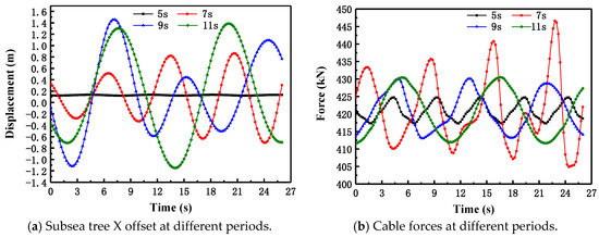
Figure 10.
Subsea tree offset and cable forces at different periods.
Figure 10a shows that an increase in the period induced a gradual increase in the offset range of the X-direction, but when the periods of 9 s and 11 s were reached, the offset remained the same. Figure 10b indicates that the maximum value of the cable pulling force was 446 kN at a period of 7 s. This phenomenon could be ascribed to the cable being about 12 m at the time, with a natural period of about 7 s when resonance occurred. When using a cable to lower the subsea tree, resonance would cause the force of the cable to change dramatically, therefore demanding careful attention.
3.2.4. Analysis of Different Lowering Speeds
According to the sea condition parameters, the flow velocity was 0.50 m/s, the period was 7 s, and the wave height was 1.5 m. Based on past experience, the lowest possible speed was selected for lowering the installation. The absolute lowering speeds of 0.1 m/s, 0.2 m/s, 0.3 m/s, 0.5 m/s, 1 m/s, and 2.0 m/s were used for the simulation calculations, while the force of the tree under different lowering speeds was studied. A force diagram of the tree is shown in Figure 11. The external force was the highest at a 2 m/s lowering speed, followed by a 1 m/s lowering speed. The other speeds had no significant impact on the force of the tree.
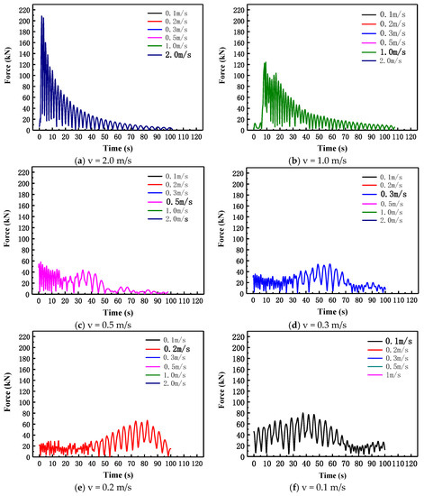
Figure 11.
Different lowering speeds of the subsea tree.
When the tree came into contact with the seawater, its relative speed was impacted by the waves. Furthermore, a reduced lowering speed was subject to a more substantial assault when the relative speed was larger. An absolute lowering speed that is too fast or too slow would induce a larger relative speed of the subsea tree and the wave, increasing the attack force of the subsea tree and seawater, as well as causing a dramatic rise in the cable force. In actual engineering, it is necessary to choose a more economical and safer devolution speed according to sea conditions. At a flow velocity of 0.50 m/s and a wave height of 1.5 m, the recommended lowering speed was 0.50 m/s.
The parameter sensitivity of the subsea tree installation stability is shown in Table 7. The wave height had the greatest influence on the installation stability of the tree, followed by the flow velocity, while the impact of the lowering speed was moderate, and the period exhibited little effect on the tree installation stability.
Table 7.
The subsea tree sensitivity.
The results from the analysis above indicate that the flow velocity should not exceed 1.50 m/s, and the wave height should not be higher than 4.5 m. In the limited area, the velocity (0 m/s, 1.50 m/s) and the wave height (0 m, 4.5 m) were interpolated. The test method repeatedly debugged multiple sets of data and determined the safety window for installing the tree, as shown in Figure 12. When the corresponding parameter falls in the green shaded area, it indicates a safe area for lowering the oil tree. Each point in this area corresponds to a suitable lowering speed. Before project construction, it is necessary to measure the current ocean parameters and predict the climatic conditions in the future, and then determine whether the installation can be performed. Moreover, comparative verification is very important, based on the theory and simulation, experimental work is needed to verify the safe climate window predicted by model.
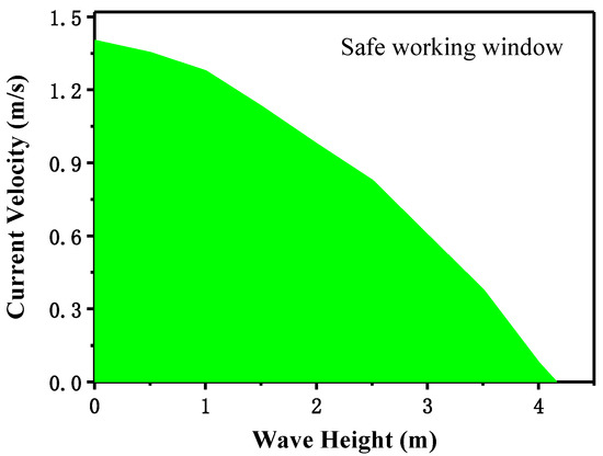
Figure 12.
The subsea tree installing safety window.
4. Conclusions
This article was based on the theory of lowering the subsea tree through the splash zone. The OrcaFlex software was used to analyze the installation process of the Lingshui 17-2 subsea tree through the splash zone under different velocities, wave heights, periods, and lowering speeds.
Subsea trees are most significantly affected by sea conditions when they pass through the splash zone. As the depth of the tree increases after entering the water, the tree offset displacement and cable forces decrease. The wave height represents the main factor involved in the offset displacement of the subsea tree and the change in cable tension. An excessively high wave height causes vertical displacement of the subsea tree. During this process, overturning accidents, damage to cables, and lifting equipment may occur, therefore demanding careful attention to the plan. Velocity mainly affects the horizontal migration of the tree during the lowering process, and there is almost no risk of the tree overturning or sudden changes in cable stress. Changes in velocity cause horizontal offset of the tree. The lower the installation speed, the higher the attack pressure may be, and it is necessary to select the safest and most economical installation speed, adhering to the marine environmental parameters. Combining the research methods above with safe operating standards allows for the determination of the safety window when the tree is installed, providing guidance for the installation.
Author Contributions
Y.L. contributed significantly to analysis and manuscript writing; H.Z. performed the numerical simulation and data analyses; N.X. contributed to the conception of the investigation; X.W. helped perform the analysis with constructive discussions; D.W. contributed to the writing-review & editing. All authors have read and agreed to the published version of the manuscript.
Funding
This work was financially supported by Ministry of Science and Technology of the People’s Republic of China (2016YFC0303701), Ministry of Industry and Information Technology of the People’s Republic of China ((2018)472), National Natural Science Foundation of China (51875578).
Conflicts of Interest
The authors declare that they have no conflict of interest.
Nomenclature
| the fluid resistance | |
| the buoyancy of the subsea tree | |
| the additional mass force of the subsea tree | |
| the gravity of the subsea tree | |
| H | air layer thickness |
| l | the length of the lowering rope |
| L | the length of the subsea tree |
| Ms | the quality of the subsea tree |
| p | the pressure of air |
| p0 | the pressure of air in the initial state |
| the cable tension | |
| u | air layer horizontal moving speed |
| v | the vertical speed of the ship crane |
| V(t) | the install speed |
| θ | the angle between the rope and the horizontal direction |
| ρ0 | the density of air in the initial state |
| ρa | the density of air |
| γ | specific heat ratio of air |
| φ | the speed of the lowering rope |
References
- Bhattacharyya, S.K.; Cheliyan, A.S. Optimization of a subsea production system for cost and reliability using its fault tree model. Reliab. Eng. Syst. Saf. 2019, 185, 213–219. [Google Scholar] [CrossRef]
- Wang, L.; Wang, X.; Lizhang, H.; Jia, P.; Yun, F.; Wang, H. Design and reliability analysis of the electrical control system of the subsea control module. Proc. Inst. Mech. Eng. Part I J. Syst. Control Eng. 2019, 233, 720–733. [Google Scholar] [CrossRef]
- Zhao, H.L.; Chen, R.; Luo, X.L.; Duan, M.L.; Lu, Y.H.; Fu, G.W.; Tian, H.P.; Ye, D.H. Metal sealing performance of subsea X-tree wellhead connector sealer. Chin. J. Mech. Eng. 2015, 28, 649–656. [Google Scholar] [CrossRef]
- Rules for Classification and Construction of Offshore Fixed Platforms; China Classification Society: Beijing, China, 2012.
- Zhang, K.; Duan, M.; Luo, X.; Hou, G. A fuzzy risk matrix method and its application to the installation operation of subsea collet connector. J. Loss Prev. Process. Ind. 2017, 45, 147–159. [Google Scholar] [CrossRef]
- Rhee, S.H.; Makarov, B. Validation study for free-surface wave flows around surface-piercing cylindrical structures. In Proceedings of the ASME 2005 24th International Conference on Offshore Mechanics and Arctic Engineering, Halkidiki, Greece, 12–17 June 2005. [Google Scholar]
- Howison, S.D.; Ockendon, J.R.; Wilson, S.K. Incompressible water-entry problems at small deadrise angles. J. Fluid Mech. 1991, 222, 215. [Google Scholar] [CrossRef]
- Cui, S.; Cheong, H.K.; Hao, H. Experimental study of dynamic post-buckling characteristics of columns under fluid–solid slamming. Eng. Struct. 2000, 22, 647–656. [Google Scholar] [CrossRef]
- Hao, H.; Cheong, H.K.; Cui, S. Analysis of imperfect column buckling under intermediate velocity impact. Int. J. Solids Struct. 2000, 37, 5297–5313. [Google Scholar] [CrossRef]
- Carcaterra, A.; Ciappi, E. Hydrodynamic shock of elastic structures impacting on the water: Theory and experiments. J. Sound Vib. 2004, 271, 411–439. [Google Scholar] [CrossRef]
- Yettou, E.M.; Desrochers, A.; Champoux, Y. Experimental study on the water impact of a symmetrical wedge. Fluid Dyn. Res. 2006, 38, 47–66. [Google Scholar] [CrossRef]
- Tveitnes, T.; Fairlie-Clarke, A.C.; Varyani, K. An experimental investigation into the constant velocity water entry of wedge-shaped sections. Ocean Eng. 2008, 35, 1463–1478. [Google Scholar] [CrossRef]
- Tian, X.; Zou, Z.; Wang, F.; Ren, H. Experimental investigation of bow flare slamming loads. Int. Soc. Offshore Polar Eng. 2014, 1, 472. [Google Scholar]
- Fraenkel, L.E.; Keady, G. On the entry of a wedge into water: The thin wedge and an all-purpose boundary-layer equation. J. Eng. Math. 2004, 48, 219–252. [Google Scholar] [CrossRef]
- Oger, G.; Doring, M.; Alessandrini, B.; Ferrant, P. Two-dimensional SPH simulations of wedge water entries. J. Comput. Phys. 2006, 213, 803–822. [Google Scholar] [CrossRef]
- Moore, M.R.; Howison, S.D.; Ockendon, J.R.; Oliver, J.M. Three-dimensional oblique water-entry problems at small deadrise angles. J. Fluid Mech. 2012, 711, 259–280. [Google Scholar] [CrossRef]
- Facci, A.L.; Porfiri, M.; Ubertini, S. Three-dimensional water entry of a solid body: A computational study. J. Fluids Struct. 2016, 66, 36–53. [Google Scholar] [CrossRef]
- Takagi, K. Numerical evaluation of three-dimensional water impact by the displacement potential formulation. J. Eng. Math. 2004, 48, 339–352. [Google Scholar] [CrossRef]
- Shi, Y.; Pan, G.; Yan, G.-X.; Yim, S.C.; Jiang, J. Numerical study on the cavity characteristics and impact loads of AUV water entry. Appl. Ocean Res. 2019, 89, 44–58. [Google Scholar] [CrossRef]
- Jiang, Y.; Bai, T.; Gao, Y.; Guan, L. Water entry of a constraint posture body under different entry angles and ventilation rates. Ocean Eng. 2018, 153, 53–59. [Google Scholar] [CrossRef]
- Shen, T.; Zhao, T.; Li, D.; Zhao, X. Numerical simulations for water entry of hydrophobic objects. Ocean Eng. 2019, 190, 106485. [Google Scholar] [CrossRef]
- Chan, E.S.; Cheong, H.F.; Gin, K.Y.H. Wave impact loads on horizontal structures in the splash zone. Int. Soc. Offshore Polar Eng. 1991, 1, 173. [Google Scholar]
- Jia, D.; Agrawal, M. Fluid-structure interaction: Lowering subsea structure/equipment in splash zone during installation. In Proceedings of the Offshore Technology Conference 2014, Houston, TX, USA, 5–8 May 2014. [Google Scholar]
- Du, Y.; Liu, G.; Duan, M.; Wang, Y. Numerical study of wave slamming forces on panels in the splash zone based on ALE method. In Proceedings of the 29th International Ocean and Polar Engineering Conference, Honolulu, Hawaii, USA, 16–21 June 2019. [Google Scholar]
- Nam, B.W.; Kim, N.W.; Choi, Y.M.; Hong, S.Y. A model test for deepwater lifting and lowering operations of a subsea manifold. Int. Soc. Offshore Polar Eng. 2016, 26, 263. [Google Scholar] [CrossRef]
- El Mouhandiz, A.A.; Troost, S. Subsea templates installation at North Sea using HLV THIALF. Int. Soc. Offshore Polar Eng. 2013, 1, 306. [Google Scholar]
- Guan, X.; Jin, Y.; Zhou, C. Offshore Engineering Technology Guide; Shanghai Jiaotong University Press: Shanghai, China, 2014. [Google Scholar]


© 2020 by the authors. Licensee MDPI, Basel, Switzerland. This article is an open access article distributed under the terms and conditions of the Creative Commons Attribution (CC BY) license (http://creativecommons.org/licenses/by/4.0/).