Abstract
The geomechanics effects and seabed subsidence are critical issues that should be considered in the development of a hydrate reservoir. The purpose of this study is to couple the geomechanics, hydrate reaction, and multiphase fluid flow modules to investigate the feasibility of CO2 enhanced gas recovery (CO2-EGR) of a Class-1 hydrate deposit by observing the formation deformation, and the seabed subsidence. The production methods of depressurization and CO2-EGR are modeled, respectively. The production behaviors and seabed subsidence of different production methods are compared. The positive influence on the gas recovery for a Class-1 hydrate deposit via CO2-EGR is observed. The calculations of seabed subsidence showed a significant improvement can be achieved when CO2-EGR was used. The subsidence is only 6.8% of that from the pure depressurization in the case of a pressure drop of 30%. The effects of production pressure drop and production gas rate are investigated. The association between the gas production and the pressure drop of the well is different from the cases of pure depressurization and the CO2-EGR. The appropriate initial time for the CO2 injection is tested. Slighter seabed subsidence is observed when the CO2 injection is initiated earlier. The case of different injection pressure control showed that a lower injection pressure leads to a heavier seabed subsidence. A higher CO2 fraction allowed in the produced gas stream results in a higher cumulative gas production, but there is no significant impact on the seabed subsidence.
1. Introduction
Gas hydrates are currently recognized as an up-and-coming energy resource. The natural gas produced from hydrate deposits has the advantages of relatively lower carbon emissions and air pollution [1,2]. Gas hydrates are solid compounds that are formed by small gas molecules and a specific amount of water molecules. Under high pressure and low temperature conditions, the water molecules tend to bond via hydrogen bonding and form crystal-like structures that create cavities between the water molecules [3].
Three major kinds of gas hydrate deposits naturally exist that have production potentials based on their geological structures, hydrate distributions, and strategies for production. Among them, Class-1 hydrate deposits possess hydrate strata with the accumulation of free natural gas beneath the hydrate bearing layer [4]. The hydrate bearing layer can also act as a cap rock for the gas layer. Class-1 hydrate deposits are also recognized as the most profitable reservoir type because of the additional gas resources under the hydrate zone. Production of the free gas without complications and extra costs is almost guaranteed [5,6].
To produce the natural gas from a hydrate deposit, the depressurization method can be used [7]. The depressurization method creates a pressure drawdown in the reservoir. As the pressure reaches the condition for hydrate equilibrium, hydrate dissociation will occur [4,8]. While this dissociation reaction continues, the reservoir temperature drops along the equilibrium line. As the reservoir cools, a greater decrease in pressure is required to drive this dissociation reaction. Depressurization is the most economical method to produce natural gas from a hydrate deposit, and it may be achieved by withdrawing fluid from inside of the reservoir. Considering this, Class-1 hydrate deposits are the best targets for the depressurization method. By producing the free gas that exists beneath the hydrate bearing layer, a pressure decrease occurs in the hydrate layer and creates a hydrate melting zone, which releases free gas into the gas zone during the gas production process [5,9].
However, most hydrate deposits occur in shallow (200–1500 m) underground without completely consolidated reservoir rocks, especially in an oceanic environment [10,11,12]. The weak structure of these reservoir rocks may lead to serious formation damage and cap rock failure during the gas extraction and hydrate dissociation processes. The risk of geological hazards that may occur during the hydrate production process must be avoided [13]. Hydrate dissociation that occurs in the reservoir releases both free gas and water, thereby influences the pore pressure. The changes in pore pressure affects the effective stress between the sedimentary grains and eventually influences the strength and stability of the hydrate deposits. The poor strength of such a formation can result in severe geological damage, including formation subsidence and collapse, the sinking of the operation wells, the destruction of the above production platform, and landslides [14,15,16]. For Class-1 hydrate deposits, another kind of potential geological hazard may occur. In Class-1 hydrate deposits, free gas is trapped underneath the hydrate layer. When no additional impermeable overburden structures exist in such a system, the hydrate layer is the most important impermeable cap rock for the accumulated free gas. By overproducing and dissociating the hydrates in situ, the integrity of the hydrate layer is diminished. Without the hydrate layer acting as a cap rock, the free gas may easily leak to the surface. In fact, the leakage of massive quantities of methane from hydrate deposits can increase the rate of climate change [17,18]. In order to prevent geological hazards from occurring during gas production from hydrate reservoirs, careful investigations of hydrate deposits and considerations of potential geological deformations are required.
As mentioned previously, Class-1 hydrate deposits are the most profitable hydrate deposits. The free gas that exists underneath the hydrate layer may be easily produced without additional costs and complex techniques. However, the risks of damage to the surrounding formation and gas leakage during production limits the production rate and overall amount of gas produced. In order to avoid hydrate dissociation and the weakening of the overlying formation, the injection of CO2 into a reservoir to maintain the hydrate layer pressure has been proposed [19,20]. By injecting CO2, the reservoir is repressurized and the contained oil and gas will be displaced [21,22,23,24,25]. There are two main reasons that CO2 is selected as the injection fluid. First, CO2 injection and sequestration during the development of new hydrocarbon energy resources can reduce the overall CO2 emissions from the combustion of hydrocarbons. Second, the technology related to CO2 enhanced gas recovery (EGR) is very mature. The application of this technology towards the development of hydrates is promising [26].
However, there is limited literature studying the feasibility of the CO2-EGR of hydrate deposits by a coupled geomechanics-hydrate-fluid flow model. As mentioned before, the geomechanics effect and formation deformation are critical issues that should be considered in the development of a hydrate reservoir. The information of the seabed subsidence is also important when the CO2-EGR is conducted for pressure management. Therefore, the purpose of this study is to establish an integrated geomechanics-hydrate-fluid flow model, by coupling the geomechanics, the hydrate reaction (dissociation/formation), and multi-phase fluid flow modules, to investigate the feasibility of CO2-EGR of a Class-1 hydrate deposit by observing the formation deformation and the seabed subsidence. This can lead to a safe operation strategy that prevents severe seafloor subsidence during gas production from a hydrate deposit.
2. Materials and Methods
2.1. Numerical Simulation
In order to simulate the hydrate behavior and gas production, many aspects must be considered including mass transfer, heat transfer, geomechanics, etc. Obtaining a solution via an analytical method is nearly impossible. Numerical methods are therefore used to solve these complex problems. In this study, the Steam Thermal Adaptive Reservoir Simulator (STARS) developed by the Computer Modelling Group Ltd. is used for hydrate simulation coupled with a geomechanics module. CMG STARS is a commercial reservoir simulator that is capable of calculating multiphase fluids flows, thermal conduction, and geomechanics [27]. In the numerical simulation, a control volume is examined. The rate of mass and heat transfer across in the control volume is considered. The rate of mass and heat change can be expressed as: Rate of change of accumulation = net rate of inflow from adjacent regions + net rate resulting from sources and sinks. The rate of change in terms of the accumulation is composed of the net mass and heat flow from the source/sink and the inflow terms. These three terms form the conservation equation in this simulator [27,28].
2.2. Gas Hydrate Reaction Module Design
CMG STARS features a kinetic-reaction module that may be used to establish the geochemical reactions required for hydrate simulations. In order to build a hydrate reaction module in this simulator, the hydrate component properties must be defined [29]. The hydrate components designed by Gaddipati [30] were represented using a thick oil-phase compound that has an extremely high viscosity and very low mobility. This design benefits from the relative permeability calculation that enables the oil-phase designed hydrates to influence the other phases of fluid flow, such as gas and water, in the reservoir [30]. On the other hand, the hydrates designed by [31] were set as solid components in STARS, and these solid phase hydrate components were used in the simulated reservoir [31]. The assumption of solid-phase designed hydrates allows the hydrates to possess mechanical properties that may influence the geomechanics of the formation during gas production. In this study, the solid phase design is adopted to study the subsidence caused by hydrate production.
The hydrate formation and dissociation reactions can be expressed as [30]:
The reaction rate can be expressed via the rate of change of the hydrate concentration [28,31]:
where is the hydrate reaction activation energy, R is the universal gas constant, T is the reservoir temperature, is the hydrate concentration, is the hydrate saturation, is the porosity, is the hydrate density, and the K is the equilibrium constant.
In the kinetic-reaction module in STARS, the “frequency,” which controls the reaction rate, can be described as:
where is the intrinsic rate constant, is the specific reaction area, is the correlation constant of the equilibrium pressure, is the water saturation, and is the hydrate density.
In the reaction calculation module, the equilibrium constant, K, is assigned to control the activation of the formation and dissociation reactions. The K value is determined by the following correlation equation:
where rxk1, rxk2, rxk3, rxk4, and rxk5 are the correlation coefficients of the equilibrium, is the reaction equilibrium pressure, and and are the correlation coefficients of the equilibrium pressure, which are determined from the experiment [3,30]. As the correlation coefficients are changed, the equilibrium temperature and pressure are also altered. In the simulation, the reaction begins when . As exceeds , K will become greater than 1 and the reaction calculation will begin. By setting K = 1, this equation can be used to obtain the desired correlation coefficients for the hydrate reaction over a certain range of reaction temperatures.
By using the experimental data for the methane hydrate reaction [3,32], a polynomial regression line for the equilibrium temperature and pressure of the methane hydrate reaction was created and used in this study, as shown in Figure 1.
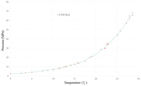
Figure 1.
Polynomial regression of the equilibrium temperature and pressure for the methane hydrate reaction.
By using Equation (4) and the polynomial regression line, a set of correlation coefficients were determined for the temperature range of 0 to 28 °C (Table 1).

Table 1.
Correlation coefficients of the equilibrium constant for methane hydrates.
2.3. Geomechanical Coupling Calculations
In CMG STARS, the geomechanical module is constructed based on the calculations of several parameters: stress (σ), strain (ε), and displacement (u). The deformations and displacements are calculated according to the basic physical properties in the geomechanical design of the reservoir, including the Young’s modulus, Poisson’s ratio, and bulk modulus. Without the geomechanical coupled calculations, the bulk volume of each grid remains unchanged during the simulation. In order to account for the influence of the geomechanical behavior of the reservoir, the relationship between the reservoir porosity and the stress is addressed using several equations. The following equations are used to calculate the strain of a deformable porous medium [33,34].
Force equilibrium equation:
where is the body force and is the total stress.
Strain-displacement relation:
where represents the displacement and is the matrix transpose function.
Total and effective stress relation:
where is the effective stress, is the Biot’s number, is the pressure, and represents the identity matrix.
Stress–strain relation:
where is the tangential stiffness tensor, is the thermo-elastic constant, and is the temperature difference. For a one-dimension case, the tangential stiffness tensor is equal to the Young’s modulus (C = E); for a three-dimension case, the tangential stiffness tensor can be expressed as:
Effective stress:
Displacement equation:
To solve these geomechanical calculations, the temperature and pressure data from the fluid flow calculations are first used in the displacement Equation (11). Then, the results obtained from the displacement equation are used to calculate the strain via the strain-displacement Relation (6). The effective stress can then be determined using the effective stress Equation (10). To couple the time-based fluid flow simulation with the geomechanical calculations, which do not involve a time-based solution, the iterative coupling method is adopted in STARS. Unlike the full coupling method, the iterative coupling method only requires certain variables to allow for the exchange of information between the flow simulator and geomechanical calculations. In STARS, these variables are the reservoir porosity and absolute permeability. The two separate sequential calculations may converge if the highest restrictive tolerance of the change in pressure, stress, or porosity is satisfied. The reservoir porosity is used in the calculation of reservoir flow. The conservation of fluid in a deformable porous media can be expressed as:
where represents the reservoir porosity, is the fluid density, is the permeability, is the fluid viscosity, is the body force of a unit mass of fluid, and is the flow rate of the fluid.
The reservoir porosity () used in Equation (12) can be calculated using the true porosity and volumetric strain obtained from the geomechanical calculations as:
where is the volumetric strain and is the true porosity.
The definition of the reservoir porosity () and true porosity () can be expressed as follows:
In this study, the permeability is set as a function of the reservoir porosity using the Carmen–Kozeny formula.
In this study, the dual-grid system was adopted for the geomechanics design, and the geomechanic calculations exceeded the region of the reservoir area reaching to the surface of the seabed. The dual-grid system represents the different designs in fluid-flow grids and geomechanics grids. Information exchange is achieved via the mapping algorithm between these the two grids system. This kind of grid design is often used when the fluid flow calculations and geomechanic behavior of a system are inconsistent. It can also be used to reduce the grid complexity in one of the grid systems to reduce the overall calculation time. The flowchart for the overall calculation of the reservoir simulator coupled with a geomechanical module is illustrated in Figure 2, where “CI” represents the coupling iteration. With the coupling iteration employed in the system, either the pressure, porosity, or mean total stress is used to confirm the calculation results. The system will converge when the most restrictive tolerance is satisfied in the calculation results.
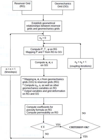
Figure 2.
A general flowchart for iterative time-based coupling and dual-grid coupling [34].
2.4. Study Process and Numerical Model Designs
In this study, a numerical model was constructed to illustrate the gas production mechanisms involved in the injection of CO2 into the free gas zone of a Class-1 hydrate deposit. The CO2-EGR strategy was tested using a hypothetical Class-1 gas hydrate reservoir model in which the formation parameters are referred to a Class-1 gas hydrate deposit located offshore of southwestern Taiwan. First, a simple depressurization production simulation was conducted as a control. The control results demonstrate depressurization-induced production without the use of CO2 injection and pressure control in the reservoir. The CO2-EGR strategy was then applied. The calculation results of the reservoir pressure, cumulative methane gas production, cumulative CO2 injection volume, volume of dissociated hydrates, and formation subsidence were compared. By comparing these results, the different operation strategies can be evaluated.
2.4.1. Numerical Model Design
The reservoir model was designed as a cubic unit of a marine hydrate reservoir with an area of 1 km2 (Figure 3, Table 2). On top of the underground reservoir, there is a 600-m thick overburden under a 2000-m deep sea. Inside of the reservoir, there is a 50-m thick hydrate zone on top of the 100-m thick free gas zone. The reservoir was designed using a gradient temperature system to distinguish the hydrate zone and the free gas zone. Two constant temperature layers exist as different temperatures are set on top of and underneath the reservoir grids. The temperature of the top constant temperature layer is 20.15 °C, and the temperature of the bottom constant temperature layer is 24.95 °C.
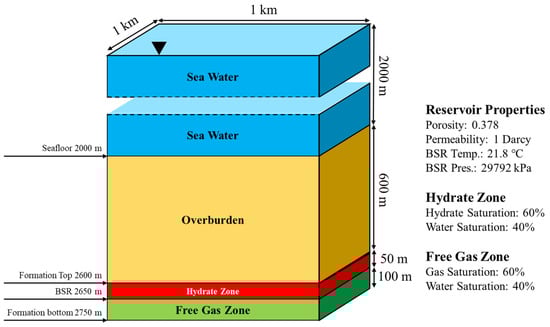
Figure 3.
Sketch of the cubic unit hypothetical Class-1 hydrate reservoir model.
Table 2.
Hypothetical Class-1 hydrate reservoir parameters.
In this study, one of the goals is to manage the pressure change in the reservoir. In order to achieve this, a horizontal production well design was considered. With a horizontal well, the hypothetical model can be further simplified to a sliced model to obtain a better simulation time and a reduced grid dimension, which allows for a better resolution of the simulation results. The model used in this study was the simplified sliced model (Figure 4), which was developed from the hypothetical cubic model.
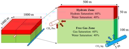
Figure 4.
Sketch of the sliced 2D hypothetical Class-1 hydrate reservoir model.
2.4.2. Geomechanics Module
In this study, the geomechanical model of the solid component and rock formation is a linear-elastic model. The rock failure was not considered in this case. The geomechanic parameters were collected from literature [35,36,37]. The Young’s modulus (elastic modulus) was calculated according to the following equation [35] that is associated with the effective confining stress of the hydrate bearing reservoir:
where is the Young’s modulus associated with the sand sediment without hydrates in the pores, and are the constants for the sand Young’s modulus calculation, and is the effective confining stress. Inside the reservoir, the effective stress was set as 29,792 kPa to calculate the corresponding Young’s modulus. According to [35], the Young’s modulus of a hydrate bearing sand may increase along the saturation increment of the solid hydrate in the pore area. The suggested formula used to calculate the hydrate-enhanced elastic modulus is:
where is the Young’s modulus increment caused by the existing hydrates, is a constant for the Young’s modulus increment caused by these hydrates, and is the hydrate saturation. In this study, the hydrate component was set as a solid component inside of the pore. Therefore, the hydrate enhancement effect can be calculated using different hydrate saturation values during the production process to demonstrate the strata weakening caused by hydrate dissociation. The Young’s modulus in STARS can be determined by:
where is the volume fraction of the matrix and fluid, is volume fraction of the hydrate, is the Young’s modulus of the reservoir without hydrates, is the hydrate-enhanced Young’s modulus, and is the scaling power, which is set as 2 by default in STARS. To simulate the hydrate reinforcement behavior in the reservoir, was determined with the use of Equation (17). The parameters used for the Young’s modulus calculations are shown in Table 3. The results of the Young’s moduli obtained using different hydrate saturation values are shown in Figure 5. The Young’s moduli obtained from Equations (17) and (18) are very close. Basically, the correlation used for the Young’s modulus in STARS has a higher generalization than the correlation from [35] because the parameter of curvature correlation (m) is used. The spatial distribution and values of the geomechanic parameters used in this study are shown in Figure 6.
Table 3.
Young’s modulus parameters [21,27].
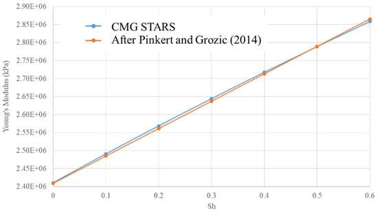
Figure 5.
The results of the Young’s moduli obtained using different hydrate saturation values.
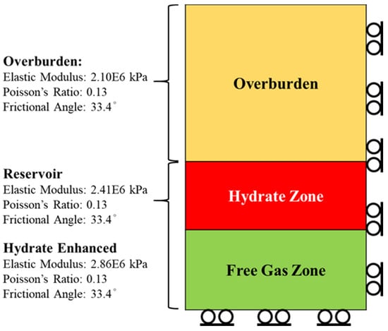
Figure 6.
Geomechanics parameters and spatial distribution.
2.4.3. Well Placement and Production Strategy
In the original cubic model, one horizontal production well penetrates the top of the free gas zone in the middle of the reservoir, and two horizontal injection wells are placed on the two sides of the reservoir boundary parallel to the production well. The model is then simplified to a sliced model that represents half of the cross section of the original cubic model. The 2D sliced model is 500-m long in the I direction (half that of the cubic model) and 150-m high in the K direction. In the J direction, there is one layer of the grid with a 5-m width. The reservoir is divided into 101 × 1 × 25 (I × J × K) grid blocks. There are five grid layers with heights of 10 m for the 50-m thick hydrate zone, and there are 20 grid layers with 5-m heights for the 100-m thick free gas zone. Table 4 shows the reservoir design parameters for the 2D slice model, and the thermal conductivity values are based on [30].
Table 4.
Sliced 2D hypothetical Class-1 hydrate reservoir design parameters [28,30,38].
In the sliced model, the production well is placed on one side at the top of the free gas zone, and the injection well is placed on the other side at the bottom of the free gas zone. The production well is set to produce at a surface gas rate of 1 MMscm/day with a maximum pressure drop of 50% of the initial reservoir pressure for a 1-km long horizontal well. Due to the specific gravity difference between the methane gas and injected CO2, the production well is better located on top of the free gas zone to delay the CO2 breakthrough that reduces the methane production. The production well is designed to stop once the CO2 fraction in the total produced gas exceeds 10% [21,39]. The injection well injects CO2 at the bottom of the free gas zone. The injection well is set to inject CO2 at the well bottom hole pressure of the initial reservoir to neutralize the depressurization. Via buoyancy flow, the methane in the free gas zone is expected to be brought upward while the injected CO2 accumulates on the bottom of the reservoir.
3. Results and Discussion
3.1. Production with Pure Depressurization
First, the pure depressurization method was applied to the reservoir to produce natural gas from the free gas zone beneath the hydrate layer. The maximum pressure drop of the horizontal production well is 50% of the initial reservoir pressure, and the maximum gas production rate is 1 MMscm/day for the 1-km-long production well. The sliced model was designed to be four-hundredths of the cubic model, and the actual gas production rate used in the sliced model is 2500 scm/day. In this section, the formation subsidence behavior is observed using different operation parameters and reservoir conditions. These tests with different variables help to elucidate the relationship between the production performances, geomechanical behaviors, and the applied parameters in this Class-1 hydrate deposit model.
Our base case was examined using the original settings that were mentioned above, and the results showed that the overall gas production after 20 years was 9.986 MMscm in the sliced model. Of the original hydrate content, 39% remains in the reservoir at the end of the production. In the initial period of the gas production, a constant production rate exists for around 3500 days, and then the pressure limitation occurs. From this point, the well bottom hole (WBH) pressure and the average (AVE) pressure of the model remains at around 15,000 kPa for the following production. Hydrate dissociation continues throughout this production time. After production constraints are reached, the reservoir stops depressurization, and the hydrate dissociation rate remains constant for a long period of time (Figure 7 and Figure 8).
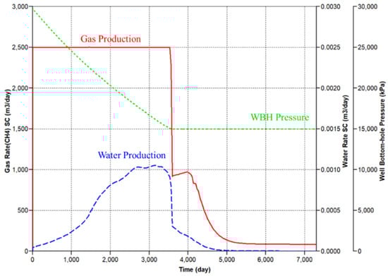
Figure 7.
Production profile of the base case production via pure depressurization, in which the WBH pressure = the well bottom hole pressure.
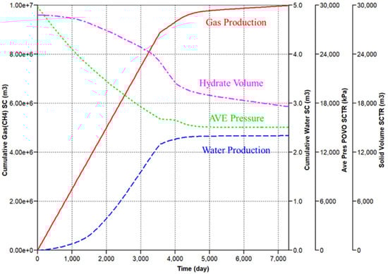
Figure 8.
Cumulative production profile of the base case production via pure depressurization, in which the AVE pressure = the average pressure.
The spatial distribution of the Young’s modulus in the reservoir is shown in Figure 9a. The original Young’s modulus of the reservoir is 2.41 × 10⁶ kPa. It is clear that the existence of hydrates strengthens the reservoir rock by increasing the value of the Young’s modulus. The reservoir Young’s modulus with the initial hydrate content is 2.86 × 10⁶ kPa. During the depressurization production, the hydrate saturation decreases due to hydrate dissociation. The reservoir strength likewise decreases along with the decrease in hydrate content. The results of the volumetric strain shown in Figure 9b also demonstrate similar spatial distribution changes due to the difference in rock strength resulting from the hydrate content. The maximum volumetric strain is located in the free gas zone without the strengthening provided by the hydrates. The formation subsidence (Figure 9c) increases during the depressurization of the reservoir. After the reservoir pressure becomes stable, the subsidence stops. The Young’s modulus changes due to the hydrate dissociation and only influences the subsidence by a small amount.
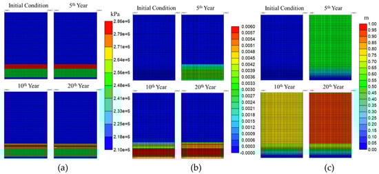
Figure 9.
Spatial distribution of the parameters of the base case production via pure depressurization: (a) Young’s modulus; (b) volumetric strain; (c) formation subsidence.
The hydrate saturation is initially 0.6. After 20-years of production, around 60% of the hydrates in the reservoir were dissociated to form water and methane gas. This dissociation gradually occurs from the center of the reservoir where the production well is located. The gas saturation in the free gas zone does not change significantly during the production because methane gas has a high compressibility that allows it to expand during reservoir depressurization. Some methane gas remains in the reservoir at the end of the production period. The reservoir temperature drops as the hydrates undergo dissociation. At the end of the production, the reservoir temperature of the hydrate zone gradually approaches a new reaction equilibrium temperature in accordance with the lower reservoir pressure, which decreases the hydrate dissociation rate. Therefore, an area in which the hydrates remain solid exists in the middle of the hydrate zone. Further dissociation of the hydrates is associated with the heat transfer from the overburden and the reservoir below (Figure 10).
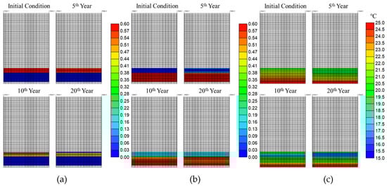
Figure 10.
Spatial distribution of the parameters of the base case production via pure depressurization: (a) hydrate saturation; (b) methane gas saturation; (c) reservoir temperature.
Finally, the estimation of seafloor subsidence is observed (Figure 11). The deformation begins to occur dramatically at the bottom of the free gas zone, and then becomes less drastic at the hydrate zone. The deformation occurs at the bottom of the overburden grids. There is no obvious cumulative formation subsidence in the overburden. The reservoir depressurization enters a relatively stable state after 10 years of production. From then, the reservoir pressure is maintained at 50% of the initial pressure, while the hydrate continues to be dissociated and causes further subsidence. The final seafloor subsidence is around 0.907 m.
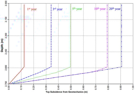
Figure 11.
The subsidence along the vertical trajectory at the production well of the base case production via pure depressurization.
3.1.1. Effect of Production Pressure Drop
The pure depressurization production method was applied using different well bottom hole pressure limitations in the production well. In this section, there are three cases that use 30%, 50%, and 70% pressure drops from the initial reservoir pressure as production limits. The results show a greater pressure drop of the production well results in a longer period of high-rate gas production. Additionally, a greater pressure difference between the initial reservoir pressure and the production well bottom hole pressure leads to a higher hydrate dissociation rate, which causes a higher gas rate after the well bottom hole pressure reaches the limitation. The water production rate profiles are not influenced by the differences in pressure drops. The same water production patterns occur as long as the gas production is maintained at 2500 scm/day.
The simulation results are shown in Table 5. In the cumulative production results, the hydrate volume in the reservoir is reduced along with the gas production. A higher pressure drop of the production well leads to a larger amount of hydrate dissociation. In the 70% pressure drop case, the hydrate dissociation ratio is over 55%, which has a negative influence on the formation stability. The cumulative gas production also shows significant improvements along with an increase in the applied pressure drop. In this study, the recovery factor (RF) in free gas zone was calculated using only the gas in the free gas zone and the overall RF includes the gas resource derived from the hydrate phase. The overall RF exceeds 64% when the 70% pressure drop is used. The difference of RF in free gas zone between the lowest and the highest values is around 50%. The subsidence observation results show a positive correlation with the pressure drop. As the reservoir pore pressure decreases, the effective formation stress increases and causes the compression of the reservoir rock, which results in vertical subsidence.
Table 5.
Results of the different production pressure drop values.
Based on the hydrate dissociation ratio and the seafloor subsidence, the lowest pressure drop case is considered to be the safest of all three cases. However, the gas production results of this case are not desirable. According to the simulation results of the pure depressurization method, a higher cumulative gas production leads to a higher risk of a potential geohazard.
3.1.2. Effect of Production Gas Rate
The production gas rate was tested at 2000, 2500, and 3000 scm/day in the slice model. A 50% pressure drop was applied for all cases. The results (Table 6) showed that the production gas rate has a large influence on the duration of production. A higher gas rate leads to a shorter production duration; however, the overall production results are relatively similar in all three cases. Increasing the production rate increases the hydrate dissociation volume in the reservoir by a small amount. The results suggest that the production rate is also related to the seafloor subsidence rate, as a higher production gas rate results in faster subsidence. However, the final subsidence results are the same across all cases.
Table 6.
Results of the different production gas rates.
3.2. CO2 Enhanced Gas Recovery
In this section, different CO2-EGR strategies are applied to the reservoir model. The simulation results are discussed to determine the effects of these strategies on the production performance, geomechanical behavior, and the operation parameters. The injection well is placed in the right-hand bottom corner of the sliced model. To avoid the overproduction of the injected CO2, the production well was set to stop when the CO2 fraction of the produced gas exceeds 10%. To maintain the initial pressure of the reservoir, different CO2 injection rates were tested to determine the ideal operation parameters. The injection rate of 3900 scm/day was found to be a stable injection parameter that provides only a small pressure drop in the reservoir. The CO2 injection rate is controlled by two constraints, which are the maximum injection rate of 3900 scm/day and the maximum well bottom hole pressure considering the initial reservoir pressure. The CO2 injection stops when the bottom hole pressure exceeds that of the initial reservoir to prevent the occurrence of hydrate reformation.
Considering the hydrate dissociation, the hydrate stabilized zone remains undisturbed during the production as a result of the CO2 injection (Figure 12a). The methane mole fraction in the reservoir is shown in Figure 12d. It was observed that the methane mole fraction decreases beginning at the bottom of the reservoir. The production ends due to the occurrence of CO2 breakthrough after 5630 days. At this time, one-fourth of the original amount of methane gas has not been produced from the free gas zone. The spatial distribution of the fluid composition shows that CO2 may lift methane (Figure 12c). This phenomenon shows the effectivity of CO2 injection and demonstrates the positive influence of this injection on methane recovery. The cumulative CO2 injection in the reservoir is 21.82 MMscm. Without hydrate dissociation, the reservoir temperature is maintained at its initial value throughout the production process. The temperature is only affected by the heat introduced by the injected CO2 (Figure 12b).
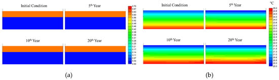
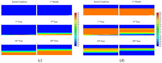
Figure 12.
Spatial distribution of the parameters of the production via CO2 enhanced gas recovery (CO2-EGR): (a) hydrate saturation; (b) reservoir temperature; (c) CO2 mole fraction; (d) methane mole fraction.
Using the same CO2 injection operation described in the preceding section, the effects of different pressure drops were tested. The CO2 injection was controlled using a constant pressure pump with a maximum injection rate of 3900 scm/day. The injection pressure constraint was set as the initial reservoir pressure and the production stopped when this pressure was reached. In this test, the use of different pressure drops showed no difference in the production results and geomechanical behaviors. Due to the limitation of the CO2 fraction in the produced gas, the production ends when CO2 breakthrough occurs. In the other words, unlike the pure depressurization case wherein the gas production is associated with the pressure drop in the production well, the production performance of the CO2-EGR strategy is majorly controlled by the CO2 injection.
The seafloor subsidence performance showed a significant improvement when CO2 injection was used. The subsidence reduces to 0.036 m, which is only 6.8% of the seafloor subsidence observed using the pure depressurization case with a 30% pressure drop (Table 7). The simulation results of the pure depressurization case and the depressurization with CO2 injection are compared. The depressurization with CO2 injection outperformed the pure depressurization case significantly in every analyzed aspect. This result is very encouraging towards the application of this method to Class-1 hydrate deposits.
Table 7.
Results of the pure depressurization case and depressurization with CO2-EGR.
3.2.1. Delayed CO2 Injection Test
In most CO2-EGR operations, the CO2 injection begins after production has already been carried out for a period of time. In this study, the delay time was designed to delay the CO2 injection. When the injection was delayed, the point at which CO2 breakthrough occurs was also delayed. Therefore, the gas production process may be elongated, and a higher cumulative gas production may be achieved. In this case, delay times of 1, 3, and 5 years were tested with the reservoir model.
The effect of the delay time on the subsidence behavior was investigated, and the results are shown in Table 8. At first glance, the observation of the final formation subsidence shows that there is only a minor subsidence of the seafloor in all the cases. However, a maximum deformation of the reservoir does not exist at the end of the production (Figure 13). As the reservoir pressure decreases, the formation is compressed. The delay time design may cause extreme pressure alterations in the reservoir, which results in harsh reservoir strain changes during operation. The unstable formation deformations may increase the risk of potential geohazards. Further CO2 injection after gas production may cause subsidence recovery in the free gas zone.
Table 8.
Results of different delay times.
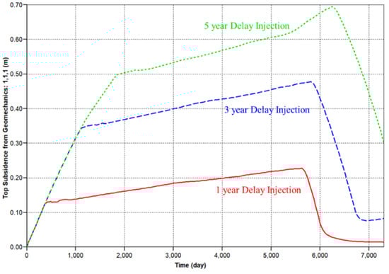
Figure 13.
Seafloor subsidence using different delay times.
3.2.2. CO2 Injection with Different Pressures
Another method to delay CO2 breakthrough involves reducing the CO2 injection pressure. By reducing the injection pressure, the injection begins when the reservoir pressure decreases below the injection pressure. In this section, three injection pressure values of 100%, 80%, and 60% of the initial reservoir pressure are tested.
Reducing the injection pressure has the same effect as increasing the delay time on the gas production behavior (i.e., the production period is extended) (Table 9). However, the injection pressure is associated to the reservoir pressure maintenance ability of the CO2 injection. As the reservoir pressure depends on the CO2 injection pressure, a lower injection pressure leads to a lower reservoir pressure and causes hydrate dissociation. A lower reservoir pressure also results in an increase in the formation subsidence.
Table 9.
Results of the different injection pressures.
3.2.3. The Limitation of the CO2 Fraction in the Produced Gas
In order to increase the overall methane gas production, the delay times and injection pressures were varied in the previous sections. However, the gas production was often observed to increase along with an increased risk of a potential geohazard. According to literature, limiting the CO2 fraction in the produced gas avoids a negative cash flow in the production project. However, no real data concerning the economic commercial production parameters for Class-1 hydrate deposits via CO2 injection exists. Therefore, different limitations of CO2 fractions in the produced gas are tested in this section.
With a higher CO2 fraction in the produced gas, the production period can be extended, and the amount of stored CO2 storage can increase (Table 10). However, a higher CO2 fraction in the produced gas results in a lower methane production rate. The methane production rate also decreases when CO2 breakthrough occurs. According to the curve of the decreasing methane production rate, the effectivity of the gas production increment achieved by raising the CO2 fraction permitted in the gas produced decreases as the CO2 fraction increases. The CO2 fraction limitation is therefore dependent on the cash flow that must be calculated using the economic parameters in each particular case in the future.
Table 10.
Results of the different limitations of the CO2 fraction in the produced gas.
4. Conclusions
We proposed a coupled geomechanics-hydrate reaction-multiphase fluid flow model to investigate the feasibility of CO2-EGR of a Class-1 hydrate deposit by observing the formation deformation and the seabed subsidence. The STARS simulator was used, and the gas hydrate reaction module was designed for the hydrate simulation, in which the solid-phase hydrate component was designed. The geomechanics was coupled with the fluid flow-hydrate reaction model to have an integrated simulation calculations of production behavior and formation deformation.
The production methods of depressurization and CO2-EGR were modeled, respectively. The production profiles, geomechanical parameters, formation deformation, and seabed subsidence of different production methods were compared. Our simulation results proved the effectivity of CO2 injection in a Class-1 hydrate deposit, and the positive influence on the gas recovery via CO2-EGR was observed. The calculations of seabed subsidence showed a significant improvement can be achieved when CO2-EGR was used. The subsidence is only 6.8% of that from the pure depressurization in the case of a pressure drop of 30%.
The effects of production pressure drop and production gas rate were investigated. We found that gas production is associated with the pressure drop in the production well in the case of pure depressurization, which is different from that of the case of CO2-EGR. The appropriate initial time for the CO2 injection was also tested. Slighter seabed subsidence is observed when the CO2 injection is initiated earlier. The case of different injection pressure control showed that a lower injection pressure leads to a higher hydrate dissociation and heavier seabed subsidence. A higher CO2 fraction allowed in the produced gas stream results in a longer production life and higher cumulative gas production, but there is no significant impact on the seabed subsidence.
Author Contributions
Conceptualization, T.-K.L. and B.-Z.H.; Methodology, T.-K.L.; Resources, B.-Z.H.; Software T.-K.L. and B.-Z.H.; Supervision, B.-Z.H.; Writing—original draft, T.-K.L. and B.-Z.H.; Writing—review & editing, B.-Z.H. All authors have read and agreed to the published version of the manuscript.
Funding
This research was funded by Ministry of Science and Technology, Taiwan, grant number MOST 108-2116-M-006-014.
Acknowledgments
This work was supported by the Ministry of Science and Technology, Taiwan (grant MOST 108-2116-M-006-014). We thank Cheng-Yueh Wu for his valuable help on this work.
Conflicts of Interest
The authors declare no conflict of interest.
References
- Sun, C.C. Introduction of global gas hydrate resources. In Proceedings of the Cross-Strait Conference on Geochemical and Environmental Geology, Washington, DC, USA, 15 December 2016; pp. 118–119. [Google Scholar]
- Zhong, S.X. Review and Prospect of Methane Hydrate; Bulletin of the Central Geological Survey, MOEA: New Taipei, Taiwan, 2005. [Google Scholar]
- Sloan, E.D.; Koh, C.A. Clathrate Hydrates of Natural Gases; CRC Press: Boca Raton, FL, USA, 2007. [Google Scholar]
- Xia, Z. Production characteristic investigation of the Class I, Class II; and Class III hydrate reservoirs developed by the depressurization and thermal stimulation combined method. J. Pet. Sci. Eng. 2017, 157, 56–67. [Google Scholar] [CrossRef]
- Moridis, G.; Collett, T. Strategies for Gas Production from Hydrate Accumulations under Various Geologic Conditions; Lawrence Berkeley National Laboratory: Berkeley, CA, USA, 2003. [Google Scholar]
- Moridis, G.J. Challenges, Uncertainties and Issues Facing Gas Production from Gas Hydrate Deposits; Lawrence Berkeley National Lab.: Berkeley, CA, USA, 2010. [Google Scholar]
- Wu, C.-Y.; Hsieh, B.-Z. Depressurization on Gas Production from Gas Hydrate Prospect on Yuan—An Ridge Offshore Southwest Taiwan. Mining & Metallurgy: The Bulletin of the Chinese Institute of Mining & Metallurgical Engineers; Elsevier: Amsterdam, The Netherlands, 2016; Volume 60, pp. 46–61. [Google Scholar]
- Merey, Ş.; Longinos, S.N. Numerical simulations of gas production from Class 1 hydrate and Class 3 hydrate in the Nile Delta of the Mediterranean Sea. J. Nat. Gas Sci. Eng. 2018, 52, 248–266. [Google Scholar] [CrossRef]
- Oragui, O. Methane Production from Gas-Hydrate Using Depressurization Method. Master’s Thesis, Civil Engineering and Geosciences, Stevinweg, The Netherlands, 2010. [Google Scholar]
- Diaconescu, C.C.; Knapp, J. Gas Hydrates of the South Caspian Sea, Azerbaijan: Drilling hazards and sea floor destabilizers. In Proceedings of the Offshore Technology Conference, Richardson, TX, USA, 6–9 May 2002. [Google Scholar] [CrossRef]
- Ruppel, C.D. Gas Hydrate in Nature; U.S. Geological Survey: Reston, VA, USA, 2018; pp. 2017–3080.
- Wu, C.-Y.; Chiu, Y.-C.; Huang, Y.-J.; Hsieh, B.-Z. Effects of Geomechanical Mechanisms on Gas Production Behavior: A Simulation Study of a Class-3 Hydrate Deposit of Four–Way–Closure Ridge Offshore Southwestern Taiwan. Energy Procedia; Elsevier: Amsterdam, The Netherlands, 2017; Volume 125, pp. 486–493. [Google Scholar]
- Yang, Y.; He, Y.; Zheng, Q. An analysis of the key safety technologies for natural gas hydrate exploitation. Adv. Geo-Energy Res. 2017, 1, 100–104. [Google Scholar] [CrossRef]
- Rutqvist, J.; Moridis, G.J. Numerical studies on the geomechanical stability of hydrate-bearing sediments. In Proceedings of the Offshore Technology Conference, Houston, TX, USA, 30 April–3 May 2007. [Google Scholar] [CrossRef]
- Gupta, S.; Helmig, R.; Wohlmuth, B. Non-isothermal, multi-phase, multi-component flows through deformable methane hydrate reservoirs. Comput. Geosci. 2015, 19, 1063–1088. [Google Scholar] [CrossRef]
- Wang, Y.; Feng, J.-C.; Li, X.-S.; Zhang, Y.; Han, H. Methane Hydrate Decomposition and Sediment Deformation in Unconfined Sediment with Different Types of Concentrated Hydrate Accumulations by Innovative Experimental system. Applied Energy; Elsevier: Amsterdam, The Netherlands, 2018; Volume 226, pp. 916–923. [Google Scholar]
- Ruppel, C.D.; Kessler, J.D. The Interaction of Climate Change and Methane Hydrates. Reviews of Geophysics; The American Geophysical Union: Washington, DC, USA, 2017; Volume 55, pp. 126–168. [Google Scholar]
- Dhakal, S.; Gupta, I. Predictive modeling of thermogenic methane hydrate formation and geobody distribution–results from numerical simulations. J. Nat. Gas Sci. Eng. 2020, 75, 103154. [Google Scholar] [CrossRef]
- Kim, T.H.; Cho, J.; Lee, K.S. Evaluation of CO2 Injection in Shale Gas Reservoirs with Multi–Component Transport and Geomechanical Effects. Applied Energy; Elsevier: Amsterdam, The Netherlands, 2017; Volume 190, pp. 1195–1206. [Google Scholar]
- Narinesingh, J.; Alexander, D. CO2 Enhanced Gas Recovery and Geologic Sequestration in Condensate Reservoir: A Simulation Study of the Effects of Injection Pressure on Condensate Recovery from Reservoir and CO2 Storage Efficiency. Energy Procedia; Elsevier: Amsterdam, The Netherlands, 2014; Volume 63, pp. 3107–3115. [Google Scholar]
- Al-Hasami, A.; Ren, S.; Tohidi, B. CO2 injection for enhanced gas recovery and geo–storage: Reservoir simulation and economics. In Proceedings of the SPE Europec/EAGE Annual Conference. Society of Petroleum Engineers, Madrid, Spain, 13–16 June 2005. [Google Scholar] [CrossRef]
- Clemens, T.; Secklehner, S.; Mantatzis, K.; Jacobs, B. Enhanced Gas Recovery-Challenges shown at the example of three gas fields. In Proceedings of the SPE EUROPEC/EAGE Annual Conference and Exhibition. Society of Petroleum Engineers, Barcelona, Spain, 14–17 June 2010; p. 17. [Google Scholar]
- Solano, S.V.; Nicot, J.-P.; Hosseini, S.A. Sensitivity Study of CO2 Storage in Saline Aquifers in the Presence of a Gas Cap. Energy Procedia; Elsevier: Amsterdam, The Netherlands, 2011; Volume 4, pp. 4508–4515. [Google Scholar]
- Kalra, S.; Wu, X. CO2 Injection for Enhanced Gas Recovery, SPE Western North American and Rocky Mountain Joint Meeting; Society of Petroleum Engineers: Denver, CO, USA, 2014; p. 15. [Google Scholar]
- Gou, Y.; Hou, Z.; Li, M.; Feng, W.; Liu, H. Coupled thermo–hydro–mechanical simulation of CO2 enhanced gas recovery with an extended equation of state module for TOUGH2MP-FLAC3D. J. Rock Mech. Geotech. Eng. 2016, 8, 904–920. [Google Scholar] [CrossRef]
- Anwar, M. CO2 capture and storage: A way forward for sustainable environment. J. Environ. Manag. 2018, 226, 131–144. [Google Scholar] [CrossRef] [PubMed]
- CMG. STARS USER GUIDE; Computer Modelling Group Ltd.: Calgary, AB, Canada, 2015. [Google Scholar]
- Wu, C.-Y. Comparisons of Different Hydrate Simulation Design for Class–1 Gas Hydrate Deposits. Ph.D. Thesis, Degree in National Cheng Kung University Department of Resources Engineering, Taipei City, Taiwan, 2018; pp. 1–114. [Google Scholar]
- CMG. Gas Hydrate Simulation Using STARS; Computer Modelling Group Ltd.: Calgary, AB, Canada, 2009. [Google Scholar]
- Gaddipati, M. Code Comparison of Methane Hydrate Reservoir Simulators Using CMG STARS; West Virginia University: Morgantown, WV, USA, 2008. [Google Scholar]
- Uddin, M.; Coombe, D.; Law, D.; Gunter, B. Numerical studies of gas hydrate formation and decomposition in a geological reservoir. J. Energy Resour. Technol. 2008, 130, 032501. [Google Scholar] [CrossRef]
- Zhou, X.; Fan, S.; Liang, D.; Du, J. Determination of Appropriate Condition on Replacing Methane from Hydrate with Carbon Dioxide. Energy Conversion and Management; Elsevier: Amsterdam, The Netherlands, 2008; Volume 49, pp. 2124–2129. [Google Scholar]
- CMG. Geomechanics Using GEM and STARS; Computer Modelling Group Ltd.: Calgary, AB, Canada, 2015. [Google Scholar]
- Tran, D.; Shrivastava, V.K.; Nghiem, L.X.; Kohse, B.F. Geomechanical risk mitigation for CO2 sequestration in saline aquifers. In Proceedings of the SPE Annual Technical Conference and Exhibition, Society of Petroleum Engineers, New Orleans, LA, USA, 4–7 October 2009. [Google Scholar] [CrossRef]
- Pinkert, S.; Grozic, J. Prediction of the mechanical response of hydrate-bearing sands. J. Geophy. Res. Solid Earth 2014, 119, 4695–4707. [Google Scholar] [CrossRef]
- Song, B. Seafloor subsidence response and submarine slope stability evaluation in response to hydrate dissociation. J. Nat. Gas Sci. Eng. 2019, 65, 197–211. [Google Scholar] [CrossRef]
- Sun, X.; Wang, L.; Luo, H.; Song, Y.; Li, Y. Numerical modeling for the mechanical behavior of marine gas hydrate-bearing sediments during hydrate production by depressurization. J. Pet. Sci. Eng. 2019, 117, 971–982. [Google Scholar] [CrossRef]
- Gaddipati, M. Reservoirs Modeling of Gas Hydrate Deposits in North Slope of Alaska and Gulf of Mexico; West Virginia University: Morgantown, WV, USA, 2014. [Google Scholar]
- Leeuwenburgh, O. Enhanced Gas Recovery—A Potential ‘U’for CCUS in The Netherlands. Energy Procedia; Elsevier: Amsterdam, The Netherlands, 2014; Volume 63, pp. 7809–7820. [Google Scholar]


© 2020 by the authors. Licensee MDPI, Basel, Switzerland. This article is an open access article distributed under the terms and conditions of the Creative Commons Attribution (CC BY) license (http://creativecommons.org/licenses/by/4.0/).