Abstract
Reversal ventilation is one of prevention methods against fire hazard in underground mines, but it is not recommended for the mines where methane is present. The authors introduce the new method of reversal and by conducting numerical simulations they prove that it allows to keep methane at the acceptable level during miners escape. However, it requires connection between the subnetworks of the main ventilation fans. It was also shown, that by using the method some escape routes will be shortened. It is possible to apply this method in the mines where the fans and stoppings are fully controlled across the full range of their operating parameters. The findings are important for underground mines, as well as for surface facilities where air control or smoke control is managed by two or more fans.
1. Introduction
An outbreak of fire in an underground mine poses major health and safety risks and results in significant material losses related to damage or destruction of machinery and devices, as well as due to the interruption of the mining process. Fires may even persist for months in circumstances where the fire outbreak is of a specific kind and isolated [1,2]. The process of combustion related to the fires, besides generating heat [3,4], causes the production of combustion products (including carbon monoxide and sulphur dioxide)—gases that are poisonous for a human [4,5,6,7,8,9]—as well as those that are explosive (methane, hydrogen) [10]. Additionally, the gases produced cause a decrease of oxygen concentration in the mine atmosphere. Due to the above reasons, underground workers should be evacuated by means of the shortest possible route containing a smoke-free air current. There are number of research into this matter for instance [11,12]. Most often, workers retreat through excavations through which smoke and fire gas flow out [9,13]. Sometimes the escape route may be very long. Studies on evacuation in an underground fire emergency were carried out by Adijski et al. and Guangwei [14,15]. In such cases, underground self-rescuer replacement stations are applied. In the case of a fire in fresh air current groups, the time taken to pass through smoke-affected mine workings may be decreased significantly by means of reverse ventilation. Among other methods, reverse ventilation may be obtained via the reverse operation of the main fan/fans. The result of such operation of the main fan is a change in the airflow direction in the mine working containing the fire outbreak [16]. In such cases, gases and smoke will also flow in the direction opposite to that prior to the reversal of the ventilation.
The fire in a longwall under a methane hazard is significantly dangerous [17]. Rosiek [18] stated that according to methane hazard reverse ventilation in an underground coal mine is hazardous. The authors pointed out that reverse operation can change potential values in a longwall what may lead to increased methane emissions to an excavation. Thus, methane concentration can not be predicted. The same thesis was pointed out by [19].
Therefore, there was a need to find a safe solution for such a case. Nowadays studies on mine ventilation network are being conducted into different aspects: field measurements and numerical evaluation [20,21], optimization of mine ventilation fan speeds [22], improving of present network methods [23,24] and risk estimation for automated ventilation systems [25]. The studies do not include reversal ventilation network analysis when gas hazard is present.
To solve the problem, in this article, there is an analysis of ventilation networks in which diagonal currents exist. It is possible to achieve a reversed direction of airflow, gases and smoke by controlling the ventilation stoppings. Such reverse ventilation is referred to as local reversion.
As mentioned above, the feasibility and advisability of reverse ventilation depends not only on ventilation hazards, but also on the structure of the mine ventilation network [19,26].
The existence of dependent air currents connecting the subnetworks of the main fans facilitates a specific means of reversing the ventilation. This method consists of adjusting the operating points of the main fans and a remote and smooth control of stoppings located at the intake of the ventilation regions [27]. The reverse operation of the main fans is not necessary in this case. The resultant reverse ventilation enables a reduction in the passage time for miners moving through mine workings that are smoke-affected and filled with gases. Taking into consideration the methane hazard, it is advantageous to maintain an unchanged airflow in the ventilation regions, including longwall areas. Thus, it is useful and necessary to maintain an automatic anemometry system. Anemometric control allows operators to verify whether manoeuvring the regulating stoppings and fan operating points has resulted in the intended effect. It should be noted that in contrast to the ventilation reversion methods described earlier, the current of air flowing through the fire location is not reversed.
The paper presents the results of calculations of air distribution in mine ventilation networks, taking into account the effects of a reverse ventilation that depends on the presence of a ventilation branch (or branches) connecting the subnetworks of the main ventilation fans. Two cases have been analysed to prove that there is a method for safe reverse ventilation in an underground mine, even when methane hazard is present.
1.1. Fire Hazard in Underground Mining
The number of fires in Polish underground mines in the years 2014–2018 reached 57 [28]. The vast majority of the fires occurred in coal mines, in which 45 fires were noted, and in copper mines—10 fires. Additionally, in the period in question, there was one fire in a salt mine and one fire in a zinc/lead mine.
In coal mines, endogenous fires were predominant—29 fires, as compared to 16 exogenous fires [28]. The endogenous fires were often located in the longwall areas—19 fires fell into this category.
In copper mines, 100% of the fires were exogenous and attributable to mechanical causes in 90% of the cases.
In the years 2014–2018, a total of 1718 miners were evacuated from zones containing smoke [28].
According to information provided by the State Mining Authority, 16 fires occurred in 2018, 3 of which were located at the surface. In hard coal mines, the number of fires reached 13, of which 8 were endogenous and 5 were exogenous. 3 fires were also noted in copper mines—all of which were exogenous [28].
According to Conti [29], Mine Safety and Health Administration (MSHA) statistics indicate that 137 fires (fires reported to MSHA) occurred in underground coal and metal/non-metal mines from 1991 to 2000 in the United States, resulting in 2 fatalities and 34 injuries (these statistics also include the Willow Creek Mine fire and explosion). A significantly higher number of unreported fires are believed to have occurred. Friction fires are the most common category of underground coal mine fires. In underground metal/non-metal mines, mobile equipment fires are the leading category of fires, following by cutting and welding and the ‘other’ category.
Considering the spontaneous combustion of coal, according to Singh [30] in the Indian coal region of Jharia Coalfield (JCF) about 1864 million tonnes of coal is lying blocked in about 65 fires. In China, the world’s biggest coal producer with an annual output of around 2.5 billion tons, coal fires are a dangerous problem. It has been calculated that some 10–20 million tons of coal is lost annually due to coal fires.
In Indonesia, inferring the data for the regions of Kalimantan and Sumatra underlain by known coal deposits, it was estimated that more than 250,000 coal seam fires have occurred in Indonesia since 1998.
1.2. Reversal of Ventilation
As Ray stated [31], reversal of the main ventilation is one of the important means of isolating a fire during emergency situations. The following two reversal types may be distinguished:
- complete reversal—in this case the direction of airflow is changed in all underground workings,
- local reversal—the change only encompasses a part of the workings.
- The reversal may be achieved using several methods:
- change of the rotor rotation direction (only in the case of axial fans allowing for flow reversal) [1],
- the use of a reversal channel and reversion gates (in the case of both axial and radial fans) [1],
- placing special reversal fans set to suction, allowing for flow reversion in downcast shafts—in normal ventilation these fans are turned off,
- placing special reversal fans set to pumping, allowing for flow reversion in upcast shafts—in normal ventilation theses fans are turned off,
- supplying water to upcast shafts,
- use of stoppings, airlocks and air crossings to achieve local reversion in areas of exploitation.
Different authors [19,20] reported that the first two methods are time consuming.
It should be added that changes in the directions of the airflow in workings are not achieved immediately after the ventilation procedure (the change of main ventilation fan rotor rotation direction or manipulating the reversing gates), but that they require a certain time to occur in all of the workings. The time required for the changes to occur is strongly dependent on the size and structure of the mine ventilation network. For instance, due to the above, the time limit of 20 min, which is required in Polish law stipulated in §158, subSection 2 of the Regulation [32] for achieving reverse ventilation in underground workings, may be exceeded. An additional hazard, especially significant in mines with a high (or very high) methane hazard, is constituted by the transition period during the process of ventilation reversal, during which the flow of air in the mine workings is very low. This reduced airflow may cause increased methane concentrations in the workings, potentially reaching explosive values, and thus contributing to the risk posed to human life [33]. It is important that the volumes of air flowing in mine workings in which humans are present should not vary unduly.
1.3. Analysis of the Structure of a Mining Ventilation Network
In the literature [19], a division of ventilation networks into 3 groups has been proposed:
- Group 1—simple networks—networks with a single downcast shaft and a single upcast shaft (Figure 1a),
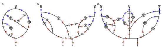 Figure 1. Canonical diagrams of ventilation networks with (a) simple structures, (b) complex structures and (c) highly complex structures [19].
 - Group 2—complex networks—networks with a larger number of peripheral upcast shafts and a larger number of centrally positioned downcast shafts (Figure 1b). By introducing stoppings in single headings, these networks may be classified in the 1st group,
- Group 3—highly complex networks—downcast shafts located in various parts of mines and with a large number of peripheral and central upcast shafts (Figure 1c). These networks are predominant in Polish mining.
The effects of the reversal performed in a single main fan station differ widely for each type of ventilation network. The highest range of reversion is achieved in mines with Group 1 networks (air currents in all workings are reversed), while the lowest range is achieved in the Group 3 networks.
The division of ventilation networks based on the number of main ventilation fans and the presence of dependent currents may be found the literature [34].
In mines with a single downcast shaft and a single return shaft, the reversed fan operation leads to a complete reversal of airflow. In networks with a higher number of upcast shafts, on the other hand, in order to achieve a reversed direction of airflow in all workings it is necessary to reverse the operation of all the main ventilation fans. Such actions have never been applied in the mining industry. The reversed operation of a single fan station in Group 3 networks does not have to cause—due to the operation of the remaining main ventilation fans—the reversal of the direction of airflow in any of the downcast shafts. In the event of a fire in a downcast shaft, the reverse ventilation of a single fan station may thus be inefficient or even increase the size of the zone directly under the influence of smoke.
The presence of diagonal currents is a significant feature of all actual ventilation networks in Polish underground mines. One of the properties of branches with such air currents is the ability to achieve reversed airflow direction [35]. Such a reversal may be achieved by changing the aerodynamic resistance of the neighbouring branches, as well as—in certain cases—by making adjustments to the operating point of the main ventilation fans.
Dependent currents are a special type of diagonal current. They may occur in intake air or in return air. The currents are characterized as linking intake and return air currents. Additionally, currents connecting subnetworks of the main ventilation fans may be distinguished among dependent currents. These currents allow for the return air to be redirected between the main fans. This may be advisable due to the energy costs of the mine, namely the decrease in costs related to the operation of the main ventilation fans. The effects are achieved by regulating the fan operation parameters, e.g., by changing the rotational speed of the rotors or by changing the inclination angle of the fan vanes.
The main part of this paper presents an analysis of the effects of reverse ventilation that has been conducted for two ventilation networks, different in terms of the presence (or absence) of the branch connecting the subnetwork of the main ventilation fans, and partial reversal (or the magnitude of partial reversal) is dependent on whether you have a branch connecting the subnetwork of the main fans.
The presented examples are based on results of numerical calculations performed by using a software package known as “WK-RP”, which enables the air distribution in a ventilation network to be determined. The advisability of carrying out such calculations has been mentioned by W. Dziurzyński [36].
2. Materials and Methods
2.1. General Methodology
To introduce the solution for safe reversal ventilation under methane hazard two methods were analysed:
- method 1—change of a one main fan’s work from exhaust to forcing (chapter 3.1)—known method, without a branch connecting sub-networks of the main ventilation fans
- method 2—modification of following parameters: working points of main fans (constant exhaust mode) and resistance of local stoppings (chapter 3.2)—a brand new method, with a branch connecting sub-networks of the main ventilation fans.
In order to compare the results, both examples include the case when the is no reversal ventilation.
The results allow to determine gas concentration, smoke presence as well as aerodynamic potentials for the nodes. When aerodynamic potential between two nodes in a section is kept at the same level, no additional methane emissions is expected [1].
Smoke presence allowed to determine the shortest escape route for the miners. The time of their movement is estimated on the basis of the following research [11,12]
2.2. Tools and Software
An iterative Hardy Cross method was implemented to compute the airflow in the ventilation network. In order to solve this, the “WK-RP” software (co-authored by employees of the Silesian University of Technology) was applied.
Required input parameters are as follows: structure of a ventilation net by determination of start and end node of a branch, aerodynamic resistance of a branch given in kg/m7, fan’s characteristic curve by giving its approximation coefficients.
Output parameters are:
- airflow rate in particular excavations, m3/min or m3/s,
- pressure loss (dissipation), Pa,
- total fan head (Pa) and their airflow rate, m3/min,
- methane rate, m3/min,
- aerodynamic potentials in the nodes, Pa,
- smoke presence.
Gas concentration can be determined knowing an airflow rate and methane rate.
The program “WK-RP” solves following equations
- Equations for nodes of the net (I Kirchoff’s law):
- Equations for cycles (II Kirchoff’s law):
- Vi—volume flow of i air stream,
- Wi—energy dissipation of i branch (pressure loss),
- Hi—head of i fan, natural draught or fire draught,
- m—number of branches in the net,
- n—number of nodes in the net,
- sji—an element of a matrix of node-branch incidence having a value: −1 when air flowing to i branch comes from j node, 1 when air from i branch flows to j node, 0 when there is no incidence between i branch and j node.
Row of sji matrix is n-1
- cki—and element of cycle-branch matrix having a value: −1 when orientation of i branch is not the same as the orientation assumed for the entire k cycle, 1 when orientation of i branch is accordant to the orientation assumed for the entire k cycle, 0 when there is no incidence between i branch and k cycle.
Row of cki matrix is ν = m-n + 1.
2.3. Assumptions and Simplifications
When calculating the airflow, it was assumed that the decrease in air pressure is directly proportional to the square of the airflow rate in the branch and that the airflow is one-dimensional along the excavation line. Calculations were carried out for steady states.
The ventilation networks for which the calculations were performed are simplified real ventilation nets of an underground Polish coal mine. Following simplifications were made: mining region was given as a single branch, parallel branches or branches connected in raw were given as a single branch, shaft bottoms were simplified. The ventilation network consists of two upcast shafts. There are two stations of main fans working under exhaust mode. This is a typical solution for underground mines. The simplifications assumed allowed for easier analysis of the issue, while not significantly affecting the results.
Methane emissions were assumed on the basis of in situ measurements [1]. The amount of methane emissions assumed is typical for Polish underground mines.
3. Examples of Calculations of Reverse Air Distribution—Results and Discussion
The analysis of different methods of reversal ventilation is presented in the following subchapters. It includes the aim, description, the results discussion and advantages and disadvantages of the case. Section 3.1 is referred to the ventilation network without a branch connecting sub-networks of the main ventilation fans. Section 3.2 is referred to the ventilation network with a branch connecting subnetworks of the main ventilation fans.
3.1. Ventilation Network without a Branch Connecting Sub-Networks of the Main Ventilation Fans
3.1.1. Description, Aim and the Results
This example consists of an analysis of the ventilation network of a mine referred to as ‘mine A’ (the canonical diagram of the network is shown in Figure 2). The air flows into the mine through two downcast shafts (marked 1–3 and 2–4, based on the branch numbers), and it flows out through two peripheral upcast shafts (branches 22–23 and 24–25). The ventilation network compromises 5 exploitation areas: A, B, C, D and E (branches 11–21, 12–21, 15–17, 16–19 and 13–18) and a functional chamber (in branch 14–17). Among the branches, one may distinguish branches with intake air dependent currents (e.g., branches 7–8, 3–5 and 4–5) and a branch with a dependent current of return air (branch 18–19). The network does not contain branches connecting the subnetworks of the main ventilation fans.
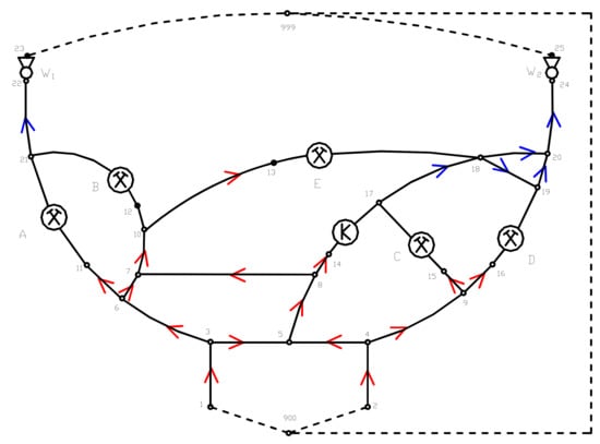
Figure 2.
Canonical scheme of mine A (own work).
In the network, it is not possible to clearly distinguish the subnetwork of the W1 fan and the subnetwork of the W2 fan. Due to this, the network may be classified as a Group 3 network—very complex in terms of ventilation reversal. In the event of a fire fresh air current in branch 3–6, the exploitation areas A, B and E will be situated in a smoke-affected zone. The dotted line represents the atmosphere.
Determination of methane emissions rate and time of escape were the aims of simulations. Fire was set up in a fresh air current. The simulations were undertaken for two cases: reversal and lack of reversal. Reversal ventilation was achieved by turning exhaust into forcing mode of W1 fan.
Methane emissions rate to particular mining sections: A, B, C, D and E were as follows: 14 m3 CH4/min, 13 m3 CH4/min, 11 m3 CH4/min, 6.5 m3 CH4/min and 15 m3 CH4/min.
Table 1 presents time of evacuation. They were determined on the basis of length of the excavations and average velocity of movement [11,12].

Table 1.
Time of miners movement in A mine (own work).
The difference of aerodynamic potentials in a section was also checked. The difference at the same level means that increased methane emissions is not expected.
Table 2 presents the results of the air and methane rate distribution calculations in a normal situation and in case of reversing the operation of the W1 fan, performed after a fire outbreak in branch 3–6.
Table 2.
Comparison of air and methane distribution in the ventilation network of mine A in the case of normal and reverse ventilation (own work).
3.1.2. Discussion
Changes in Air Distribution
From analysing the results of calculations of the reversed airflow (Table 2), it can be seen that the smoke and gases produced by the fire in branch 3–6 (fire outbreak location) were directed mostly to the shaft 1–3, and then to the surface. The airflow in the branch from node 6 to node 3 amounted to 1346 m3/min (at a normal airflow in the section from node 3 to node 6 of 2436 m3/min). In shaft 1–3, 1259 m3/min of air was flowing towards node 1. A small amount of smoke (airflow of 86 m3/min) passed through a number of stoppings in branch 3–5 to node 5. In this node, the air currents were mixing together: the air from smoke-affected node 3 and that from smoke-free node 4. After the mixing process, the air flowed into the functional chamber; areas C and D were not under the influence of smoke. Of course, the direction of flow of air was reversed in the A and B areas.
While comparing the airflow rates in each of the branches before and after reversal, it can be noted that there is a difference in the values, for instance, in the C and D exploitation areas the differences reached 20%. An even greater increase of air volume after reversing the ventilation—reaching 80%—was observed in the E area. This was caused by the cooperation of fans W1 and W2. It was also the result of the diagonal orientation in relation to the closing branch of the branches 10–13–18. These observations allow us to conclude that in networks structurally similar to the network presented in the example, the reverse ventilation achieved by means of reversing the fan in one of the shafts may cause significant changes in the ventilation of mine workings, both in terms of direction and in terms of the volume of air flowing in each of the workings. Such changes may result in the permitted air speeds in workings being exceeded, as well as a considerable increase in the difference in aerodynamic potentials between the initial and final nodes of a longwall (e.g., the E exploitation area—Table 2).
Escape Routes
According to the rules the miners must escape in the same direction as smoke flows. Miners from A and B sections go to W1 shaft and go to the node 23 where there is no smoke (Figure 2). Miners from E section go to node 18 and to branch 17–18. This branch is without smoke.
Routes and times for miners from sections A, B and E (adverse location—beginning of the mining district) are as follows:
- A—through branches 11–21, 21–22, 22–23 – 51 min + 75 min + 1 min = 127 min,
- B—through branches 12–21, 21–22, 22–23 – 48 min + 75 min + 1 min = 124 min,
- E—through branches 13–18 – 36 min.
After reversal smoke will flow to upcast shaft and minimal amount of smoke will flow to a function chamber, although mining sections will not be under smoke. Miners being in the chamber can go to the node 17 (clean air from C). Evacuation time is 8 min (only through 14–17).
Lack of smoke in mining sections and short evacuation time could indicate that this known method is correct. However, as so far methane hazard has not been considered.
Methane
The difference in aerodynamic potentials may result in increased or decreased emissions of methane to the longwall area and thus an increased/decreased methane hazard level. When reversal ventilation was turned on the differences were as follows:
- A—increase 166 Pa, change of potential assignment,
- B—increase 299 Pa, change of potential assignment,
- C—decrease 140 Pa, no change of potential assignment,
- D—decrease 95 Pa, no change of potential assignment,
- E—increase 528 Pa, no change of potential assignment.
Considering methane hazard, a decrease of the potential in C and D is advantageous. It makes lower methane emissions to excavations. An increase of the potential is computed for A, B and E. It means increase of methane emissions to the excavations. The worst situation is for E. The potential is increased threefold. Detailed determination of methane emissions increase in such a situation is almost impossible [37,38]. The process is very dynamic, there is an influence of baric pressure variations and usually gobs are not known sufficiently. Although, it can be stated that under reversal ventilation methane from B and approximately 10% of methane from A will flow to E. As a result amount of methane in E is 29.8 m3/min, when without reversal it was 15 m3/min. Thus, it is almost 100% increase. However, it’s temporary [39].
Decreasing the volume of air or even a momentary interruption of the airflow in the workings in which the ventilation has been reversed (for example, in the A and B exploitation areas—Figure 2, Table 2), may cause an increased methane concentration in these mine workings, up to values exceeding the allowable limits permitted by regulations. In some cases, this may lead to production of an explosive methane and air mixture.
Advantages and Disadvantages of Reversal Ventilation
Decrease of smoke area is advantage. Section A, B and E are not smoked. The miners are safe there. Smoke flows through branch 1–3 to the surface.
Disadvantages are as follows:
- increase of methane hazard, particularly in section E (according to increase of aerodynamic potentials),
- change of air direction and amount in excavations. They can not fill the regulations,
- reversal of air direction in sections A and B, at some moment it leads to lack of air movement,
- minimal smoke amount in a function chamber.
For this reason, the application of reverse ventilation in mines with high methane hazards, achieved by means of reversed operation of the main ventilation fans, is a risky procedure. The decision to refrain from performing reverse ventilation in mines with methane hazard during a fire outbreak may thus be substantiated and may be reflected in the firefighting plan of a mine with a high methane hazard.
3.2. Ventilation Network with a Branch Connecting Subnetworks of the Main Ventilation Fans
3.2.1. Description, Aim and the Results
In this example, as compared to example 1, 20–21 branch has been added, located in the used air zone and connecting the subnetworks of the main fans. A canonical diagram of this network is shown in Figure 3, while the distribution of air in a normal situation is given in Table 3.
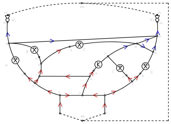
Figure 3.
Canonical scheme of mine B (own work).
Table 3.
Airflow distribution in mine B in the case of normal ventilation (own work).
Branches containing fans have been marked as bolded, while branches with exploitation areas and a chamber have been marked in italics. The negative (direction) airflow in branches 7–8 and 20–21 indicate the fact that the actual direction of the airflow in these branches is from node 8 to node 7 and from node 21 to node 20 as shown in Figure 3.
The aim was the same as for 3.1. However, different method of reversal was applied. By adjusting the operating points of the main fans and through changes in the settings of the regulation stoppings located at the mouths of the exploitation areas, the airflow in the 20–21 branch may be reversed while maintaining identical (as compared to the initial state) amounts of air in the exploitation areas and the functional chamber. The air distribution depicting such a procedure is shown in Table 4.
Table 4.
Airflow distribution in mine B in the case of reverse ventilation (own work).
Comparing the results with the previous example, methane emissions rate to particular mining sections is constant. Evacuation times are the same as in Table 1. Time of evacuation for added branch 20–21 is 83 min.
3.2.2. Disscussion
In the event of a fire outbreak in branch 3–6 and the reversed operation of fan W1, numerical calculations not provided herein reveal the occurrence of a situation similar to that obtained in example 1 (a slight inflow of smoke to the functional chamber and considerable changes in terms of the volumes of air in the exploitation areas, as compared to the normal state).
Changes in Air Distribution
The presence of the 20–21 branch, which is a diagonal branch with a dependent current connecting the subnetworks of the main ventilation fans, allows a local reverse ventilation to be achieved. This reverse ventilation is made possible not only due to the adjustment of the main ventilation operating points (e.g., by means of changing the direction of rotor rotation and/or changes in the inclination angle of the main fans’ vanes), but also due to the possibility of different (in terms of quantity) removal of air from the exploitation areas and chambers to each of the main fans.
In the distribution of air presented in Table 3—normal ventilation, 2368 m3/min of air flows towards fan W1 and 3909 m3/min flows towards the W2 fan. The total flow of air through the mine reaches 6277 m3/min.
While comparing the air distributions presented in Table 3 and Table 4, it may be noted that the volumes of air in exploitation areas and the chamber are identical and that the air current was reversed in branch 20–21 in the reverse ventilation procedure. In the case of normal ventilation airflow rate was 158 m3/min, direction was from node 21 to node 20. In the case of reversion airflow rate was 274 m3/min (opposite direction). The achievement of reverse distribution was possible by means of increasing the aerodynamic resistance of branches 6–11 and 10–12, and via adjustment of the main ventilation fans’ operating point (changes in pressure differences and airflow volume of the W1 and W2 fans, Table 3 and Table 4). It should be added that to achieve such a reverse air distribution in a part of the network, the reversed operation of the main ventilation fan is not necessary. The adjustment of the main ventilation fans’ operating points in both the upcast shafts is sufficient. To fulfil the legal requirements regarding the time to perform the reversal of the ventilation, the automation of regulating stoppings is necessary to allow quick and remote control of their parameters. Solutions consisting of the remote control of stoppings are known [40].
Escape Routes
In this case, fire situated in the branch 3–6 (fresh air current) causes smoke in sections A, B and E. Considering smoke in the branch 20–21 the miners from sections A and B must go to the node 23. The miners from section E must go to the node 18 (Figure 3). There is no smoke in the nodes 23 and 18. Escape routes and times are the same as for 3.1:
- from A—127 min,
- from B—124 min,
- from E—36 min.
Reversal ventilation achieved by regulation of working points of W1 and W2 fans and by regulation of resistance of the stoppings leads to change of air direction in the branch 20–21.
The inflow of clear air from node 20 to node 21 is an advantage resulting from reversing the flow of air in the 20–21 branch. In the event of a fire in an intake group of air currents (branch 3–6), this results in shorter escape routes from the A and B exploitation areas and smaller zones under the direct influence of smoke. Workers present in the E region should be able to reach node 18, to which fresh air without smoke flows from the 17–18 branch. Escape routes and times are as follows:
- from A—through the branch 11–21—51 min,
- from B—through the branch 12–21—48 min,
- from E—through the branch 13–18—36 min.
The presence of the branch connecting subnetworks of the main fans (such as branch 20–21, Figure 3) may turn out to be beneficial for yet another reason. If this branch contained a number of stoppings, then the airflow—and thus the air speed in the branch—would be low (it should, however, allow for a minimal air speed resulting from the provisions of law). In such case, workers from the A and B areas would be able to move through the mine workings faster than the smoke flowing in the branch.
Methane
In this case, air distribution is partly the same as for normal ventilation (fresh air currents before entering mining sections and the function chamber). Airflow rates in the sections and in the chamber are also the same (Table 3 and Table 4). Table 5 presents that the differences of the potentials in the sections are the same, too. They are:
Table 5.
Aerodynamic potentials in the nodes for reversal and normal venilation (own work).
- A—branch 11–21—424 Pa,
- B—branch – 12–21—458 Pa,
- C—branch 15–17—349 Pa,
- D—branch 16–19—354 Pa,
- E—branch 13–18—256 Pa.
Thus, it can be pointed out that there will be no additional methane emissions to the sections. In this case, they are the same for normal as well as for reversal ventilation:
- A—14 m3 CH4/min,
- B—13 m3 CH4/min,
- C—11 m3 CH4/min,
- D—6.5 m3 CH4/min,
- E—15 m3 CH4/min.
It leads to the most important conclusion. The new method (ventilation network with a branch connecting subnetworks of the main ventilation fans) does not increase methane hazard in the mining sections.
Advantages and Disadvantages of the New Method
To summarize, the ventilation procedure presented in example 2 consists of an adjustment of the main ventilation fans’ operating points (without the need for reverse operation of any of the main fans) and in changes in the resistance of the regulation stoppings at the mouths of the exploitation areas. As a result, the direction of the used air flow in the branch connecting the subnetworks of the main ventilation fan is changed, which is necessary for the reduction of the time in which workers are in the section of the smoke-affected escape route. The described ventilation procedure should thus be considered a special kind of local reversion.
The application of the ventilation procedure is also beneficial in terms of maintaining a stable airflow in these areas. The maintenance of an unchanged airflow (in relation to conditions prior to the procedure) in the exploitation areas is beneficial due to methane hazard prevention. This is because an unchanged airflow will contribute to the maintenance of the current conditions of methane release to the longwall areas and thus to maintaining methane concentrations within the limits set out under provisions of law.
Advantages:
- shorter time of evacuation from the sections A and B. Time required from E remains the same,
- keeping constant air distribution beyond and in the sections, keeping constant difference of the potentials in the sections,
- lack of methane hazard increase (according to mentioned above points).
- However, the method requires additional measures (disadvantage). To conduct the ventilation procedure presented in Example 2, it is necessary to fulfil the following three conditions:
- the presence of a return air current connecting the subnetworks of the main ventilation fans in the mine ventilation network,
- the ability to adjust the operating points of the main ventilation fans,
- the possibility of smooth and remote change of resistance of regulating stoppings.
4. Conclusions
- (1)
- As so far, reversal ventilation in underground mines where methane hazard is present has been considered as dangerous. The authors proved that there is a method to perform safe reversal, keeping methane hazard at an acceptable level. It requires connection between the subnetworks of the main ventilation fans. The results of numerical computation of air distributions in mine ventilation networks presented in Examples 1 and 2 confirm the significance of the connection which is required for performing the kind of reverse ventilation that enables safe egress of workers due to fire in an intake group air current.
- (2)
- In highly complex networks which do not contain a branch connecting the main ventilation fan subnetworks (example 1), the reverse operation of a fan may cause considerable changes in the volumes of air flowing in the exploitation areas. This could lead to permissible air velocity parameters being breached and an increased methane hazard. The decision not to perform the reversal in such networks in mines with high methane hazards may thus be substantiated.
- (3)
- In highly complex networks containing branches connecting subnetworks of main ventilation fans (example 2), the reverse ventilation in part of the network may be conducted by adjustment of the main fans’ operating points and changing the resistance of regulating stoppings while maintaining the airflow in the exploitation areas.
- (4)
- The reverse ventilation described in example 2 reduces the time in which workers are present in the part of the escape route containing smoke and decreases the size of the smoke-affected zone while maintaining methane safety in the exploitation areas.
- (5)
- To perform the ventilation procedure presented in example 2, the following elements are necessary: the presence of a branch connecting the subnetworks of the main ventilation fans, the possibility of smooth and remote adjustment of the fan operating points and of the regulating stoppings.
- (6)
- It is advisable for the devices regulating the airflow and the main ventilation fans to be fully automated, that is, allowing for remote and smooth changes of their parameters. Applying such facilities could reduce the time required for reversal.
Given methods, particularly the second one, indicate directions and perspectives for further research. It would be necessary to solve economical issues of the method. It’s clear that the method requires change of working point of the fans, thus, the costs will also vary. It would be also interesting to apply the method for more complex networks, including more than two main fans.
Author Contributions
Conceptualization, G.P.; Methodology, G.P.; Validation, G.P., Z.R., P.W. and A.N.; Formal Analysis, G.P., P.Z. and V.Z.; Resources, Z.R. and P.W.; Writing—Original Draft Preparation, G.P., P.W. and Z.R.; Writing—Review & Editing, V.Z. and P.Z. All authors have read and agreed to the published version of the manuscript.
Funding
This research received no external funding.
Acknowledgments
Appreciations for Tim Harrell for English proof reading of the text. This research did not receive any specific grant from funding agencies in the public, commercial, or not-for-profit sectors.
Conflicts of Interest
The authors declare no conflict of interest.
References
- Wacławik, J. Wentylacja Kopalń; AGH: Krakow, Poland, 2010; pp. 328–340. [Google Scholar]
- Saulov, D.; Klimenko, A.Y.; Torero, J.L. Underground fire prospective technologies. In Underground Coal Gasification and Combustion; Woodhead Publishing: Sawston, UK, 2018; pp. 583–599. [Google Scholar]
- Hansen, J. Full-scale fire experiments in an underground mine. In Proceedings of the 3rd International Symposium on Mine Safety Science and Engineering, Montreal, QC, Canada, 13–19 August 2016; pp. 13–19. [Google Scholar]
- Cheng, L.H.; Ueng, T.H.; Liu, C.W. Simulation of ventilation and fire in the underground facilities. Fire Saf. J. 2001, 36, 597–619. [Google Scholar] [CrossRef]
- Yuan, L.; Thomas, R.A.; Rowland, J.H.; Zhou, L. Early fire detection for underground diesel fuel storage areas. Process Saf. Environ. Prot. 2018, 119, 69–74. [Google Scholar] [CrossRef] [PubMed]
- Yuan, L.; Zhou, L.; Smith, A.C. Modeling carbon monoxide spread in underground mine fires. Appl. Therm. Eng. 2016, 100, 1319–1326. [Google Scholar] [CrossRef] [PubMed]
- Dudzińska, A.; Cygankiewicz, J. Analysis of adsorption tests of gases emitted in the coal self-heating process. Fuel Process. Technol. 2015, 137, 109–116. [Google Scholar] [CrossRef]
- Hansen, R. Modelling temperature distributions and flow conditions of fires in an underground mine drift. Geosyst. Eng. 2018, 1–16. [Google Scholar] [CrossRef]
- Chen, P.; Guo, S.; Wang, Y. Human evacuation affected by smoke movement in mine fires. Int. J. Coal Sci. Technol. 2016, 3, 28–34. [Google Scholar] [CrossRef]
- Wang, Y.; Li, X.; Wang, W.; Guo, Z. Experimental and in-situ estimation on hydrogen and methane emission from spontaneous gasification in coal fire. Int. J. Hydrog. Energy 2017, 42, 18728–18733. [Google Scholar] [CrossRef]
- Adjiski, V.; Mirakovski, D.; Despodov, Z.; Mijalkovski, S. Simulation and optimization of evacuation routes in case of fire in underground mines. J. Sustain. Min. 2015, 14, 133–143. [Google Scholar] [CrossRef]
- Adjiski, V.; Despodov, Z. Methodology for Optimal Fire Evacuations in Underground Mines Based on Simulated Scenarios. In Fire Safety and Protection; IntechOpen: London, UK, 2020; pp. 1–24. [Google Scholar]
- Nawrat, S.; Napieraj, S. The application of the simulation program for the analysis and design of the evacuation of mining crews from fire hazard areas. Bezpieczeństwo Pracy Ochrona Środowiska Górnictwie 2012, 8, 3–7. [Google Scholar]
- Adjiski, V.; Zubicek, V.; Despodov, Z. Monte Carlo simulation of uncertain parameters to evaluate the evacuation process in an underground mine fire emergency. S. Afr. Inst. Min. Metall. 2019, 119, 907–917. [Google Scholar] [CrossRef]
- Guangwei, Y.; Dandan, F. Escape route planning of underground coal mine based on improved ant algorithm. Math. Probl. Eng. 2013, 32–46. [Google Scholar] [CrossRef]
- Strzemiński, J. Main ventilation reversion in hard coal mines. Mechanizacja Automatyzacja Górnictwa 1998, 1, 31–37. [Google Scholar]
- Szlązak, N.; Szlązak, J. Ventilation of wall workings in coal mines in condition of methane and fire hazard. Górnictwo Geologia 2013, 8, 115–131. [Google Scholar]
- Rosiek, F.; Sikora, M.; Urbański, J. Main Ventilation Reversion in LGOM Mines. Min. Sci. 2007, 9, 89–105. [Google Scholar]
- Szlązak, N.; Zając, K. Ocena Możliwości Wykonania Rewersji Wentylacji Głównej w Kopalniach Węgla Kamiennego; Biblioteka Szkoły Eksploatacji Podziemnej: Kraków, Poland, 1998; pp. 1–90. [Google Scholar]
- Arif, W.; Kyuro, S.; Yuichi, S.; Yoshiaki, S.; Hiroyuki, T.; Kagemi, U.; Hiroyuki, M. Assessment of air dispersion characteristic in underground mine ventilation: Field measurement and numerical evaluation. Process Saf. Environ. Prot. 2015, 93, 173–181. [Google Scholar]
- Hasheminasab, F.; Bagherpour, R.; Aminossadati, S.M. Numerical simulation of methane distribution in development zones of underground coal mines equipped with auxiliary ventilation. Tunn. Undergr. Space Technol. 2019, 89, 68–77. [Google Scholar] [CrossRef]
- Thakur, P. Advanced Mine Ventilation: Respirable Coal Dust, Combustible Gas and Mine Fire Control; Woodhead Publishing: Cambridge, UK, 2018; pp. 61–77. [Google Scholar]
- Stewart, C.M.; Aminossadati, S.M.; Kizil, M.S. Improving the Performance of the Hardy Cross Algorithm for Large Ventilation Models. 2019. Available online: espace.library.uq.edu.au (accessed on 4 April 2020).
- Tabibian, S.M.; Najafabadi, M.K.; Shahizare, B. Review of common fire ventilation methods and Computational Fluid Dynamics simulation of exhaust ventilation during a fire event in Velodrome as case study. SN Appl. Sci. 2019, 1, 685. [Google Scholar] [CrossRef]
- Sabanov, S.; Tussupbekov, Y.; Aldoamzharov, B.; Karzhau, A.S.; Mukhamedyarova, Z. Risk Estimation Approach Considering Implementation of Automated Ventilation Systems into Kazakhstan Metal Mines. In Proceedings of the 28th International Symposium on Mine Planning and Equipment Selection—MPES, Perth, Australia, 2–4 December 2019; Topal, E., Ed.; Springer: Berlin/Heidelberg, Germany, 2019. [Google Scholar]
- Dziurzyński, W.; Krach, A.; Pałka, T. Method of ventilation reversal in regions containing ascending and descending currents in the conditions of fire and methane explosion hazards. Górnictwo Geologia 2013, 8, 19–34. [Google Scholar]
- Pach, G. Safe and energy-efficient ventilation in mines–application of the golden ratio method in designing forced air distribution for ventilation networks. Conference Mining—Prospects and threats, Coal—Cheap, clean energy and workplaces. In IOP Conference Series: Earth and Environmental Science; PublisherIOP Publishing: Bristol, UK, 2018; Volume 198. [Google Scholar]
- State Mining Authority. 2019. Available online: http://www.wug.gov.pl/bhp/stan_bhp_w_gornictwie (accessed on 8 November 2019).
- Conti, R.S. Responders to Underground Mine Fires. In Proceedings of the 32nd Annual Conference of the Institute on Mining Health, Safety and Research, Salt Lake City, UT, USA, 5–7 August 2001; pp. 111–121. [Google Scholar]
- Singh, R.V.K. Spontaneous Heating and Fire in Coal Mines. Procedia Eng. 2013, 62, 78–90. [Google Scholar] [CrossRef]
- Ray, S.K.; Sahay, N.; Singh, R.P.; Singh, A.K.; Bhowmick, B.C. Reversal of underground mine ventilation. J. Mines Met. Fuels 2002, 50, 339–344. [Google Scholar]
- Minister of Energy. Regulation of the Minister of Energy on specific requirements for running underground mining facilities. Dziennik Ustaw, 23 November 2016. [Google Scholar]
- Trenczek, S. Assessment of methane and spontaneous fire hazards level in the areas ventilated by refreshment of returned air in light of the applicable regulations. Przegląd Górniczy 2017, 73, 21–28. [Google Scholar]
- Pach, G. Substitute characteristics of ventilators in the forced airflow problems. Systemy Wspomagania Inżynierii Produkcji 2017, 6, 232–246. [Google Scholar]
- Krach, A. Determining diagonal branches in mine ventilation networks. Arch. Min. Sci. 2014, 59, 1097–1105. [Google Scholar] [CrossRef]
- Dziurzyński, W.; Krawczyk, J. Calculation possibilities of selected simulation programmes applied in the world mining industry describing the flow of air, fire gases and methane in the mine workings network. Przegląd Górniczy 2012, 68, 1–11. [Google Scholar]
- Trutwin, W. Zmiany ciśnienia bezwzględnego w rejonie ściany jako wskaźnik zagrożenia metanowego. In Prace Instytutu Mechaniki Górotworu; Instytut Mechaniki Górotworu PAN: Kraków, Poland, 2012; pp. 239–244. [Google Scholar]
- Lolon, S.; Brune, J.; Bogin, G.; Grubb, J.; Saki, S.; Juganda, A. Computational fluid dynamics simulation on the longwall gob breathing. Int. J. Min. Sci. Technol. 2017, 27, 185–189. [Google Scholar] [CrossRef]
- Lunarzewski, L.W. Gas emission prediction and recovery in underground coal mines. Int. J. Coal Geol. 1998, 35, 117–145. [Google Scholar] [CrossRef]
- Konsek, S.; Mazurek, C.; Jędrzejek, K.; Słowik, A. Regulacja przewietrzania w grupowym prądzie powietrza odprowadzanym do szybu wydechowego jako element optymalizacji i stabilizacji sieci wentylacyjnej kopalni na przykładzie KWK Jankowice. In Górnictwo, Perspektywy, Zagrożenia. Klimatyzacja, Zagrożenia Aerologiczne; P.A. Nova: Gliwice, Poland, 2014; pp. 62–70. [Google Scholar]


© 2020 by the authors. Licensee MDPI, Basel, Switzerland. This article is an open access article distributed under the terms and conditions of the Creative Commons Attribution (CC BY) license (http://creativecommons.org/licenses/by/4.0/).