Abstract
In order to improve the Direct Current (DC) bus utilization ratio and realize harmonic suppression of a five-phase induction motor, the SVPWM (Space Vector Pulse Width Modulation) algorithm was researched in depth. Based on an analysis of the present SVPWM algorithm and the volt-second balance principle, a dynamic and adjustable new pattern four-vector SVPWM algorithm was proposed. The algorithm uses the modulation index and zero vector to improve the characteristics of the inductor motor, the function relationship with real-time dynamic ratio between the action–time ratio of the space voltage vector and the modulation index was proposed to maximize DC bus utilization ratio, and the random zero-vector dynamic modulation mode was used to reduce harmonic influence, being able to spread harmonics concentrated around certain frequencies across a wider frequency band and thus produce a more continuous and uniform power spectrum. The new algorithm model was built using Matlab/Simulink, and the simulation and experimental results demonstrated that the algorithm is effective and feasible.
1. Introduction
Five-phase induction motor drives show several advantages over three-phase induction motors, such as lower voltage with high power, small torque ripple, high fault-tolerance capability, lower DC (Direct Current) link current harmonics, high reliability, high efficiency, lower current with equal voltage, and high torque density, which suggests many applications in electric locomotive, electric ship propulsion, aerospace engineering, and wind power [1,2,3,4,5,6,7]. Five-phase induction motors are generally driven by a multi-phase voltage/current source inverter, which is composed of a speed/torque control system with a controller and sensor. In recent years, the PWM (pulse-width modulation) multi-phase inverter control method and variable-speed multi-phase motor control strategy have become two research hotspots in multi-phase motor applications. SVPWM (space vector pulse-width modulation) using the method of vector combination is widely used in the multi-phase motor driving field because of its advantages of small torque ripple and current distortion, clear concept, better flexibility, and easy digital implementation compared with SPWM. More harmonics, larger noise and switch loss, and lower DC bus utilization are the main problems with SVPWM if it is not implemented properly. Many SVPWM control methods have been proposed to solve the above problems in different applications [8,9,10,11,12,13,14,15,16,17,18]. A new coordinate system SVPWM method was developed to eliminate common-mode voltage for multi-level inverters [8]; a five-phase SVPWM algorithm based on a modulation function was used to improve the computing speed and precision, replacing the traditional multiplication and division operation [9,10]; zero-sequence signal injection for a carrier-type multiphase inverter was used to improve PWM wave characteristics and reduce the influence of harmonics on the system [11]; reference voltage decomposition was used to calculate a multi-level space vector to simplify calculations and optimize the switching state [12]; a model of a three-phase VSI (voltage source inverter) and CSI (current source inverter) was presented and the THD (total harmonic distortion) of two models was analyzed based on the SVPWM technique [13]; and a novel SVPWM control technique for a nine-phase induction motor was used to improve the linear modulation region and create a better harmonic profile [14]. The random SVPWM method has attracted attention as a solution in recent years [15,16,17,18]. The random pulse modulation technique, the fixed sample frequency and variable switching frequency SVPWM strategies, and the dual random technique are the main research topics. A hybrid SVPWM technique was used to obtain an optimum switching sequence and reduce the instantaneous voltage error for a three-phase motor [15], a random selection of carriers between two triangular signals and random pulse-width modulation were combined to improve DC bus utilization and randomization of the harmonic power in a three-phase motor [16], a random forest regression SVPWM algorithm was proposed to improve the performance of a motor [17], and a non-sinusoidal random SVPWM strategy based on a randomized switching time delay and randomized distribution of the zero vector was used to improve the high-frequency performance of a five-phase motor and to realize harmonic dispersion [18]. Improving the performance of five-phase motors based on SVPWM strategies is still an active research area.
To improve DC bus utilization and reduce harmonic influence, this paper proposes a dynamic and adjustable new pattern four-vector SVPWM algorithm, which combines a dynamic ratio space vector and an adjustable zero-vector action time modulation mode for a five-phase induction motor to improve the DC bus voltage utilization rate and reduce the harmonics. Section 2 shows the structure and characteristic of the five-phase induction motor. Section 3 presents the characteristics of the space voltage vector of the five-phase induction motor and the relationship between the DC-link voltage and the reference voltage. Section 4 explains the principle of the proposed dynamic and adjustable new pattern four-vector SVPWM algorithm. Finally, the corresponding simulation model was established using Matlab/Simulink, and proved the feasibility of the proposed method. The experimental results demonstrated that the proposed algorithm is effective and feasible.
2. Five-Phase Induction Motor Components and Structural Characteristics
Figure 1 shows the structure topology of a five-phase induction motor. The rotating reference frame dq0 and stationary reference frame αβ0 were used to analyze the characteristics of the five-phase induction motor. The d axis and α axis are coincident in the initial state. The conversion relationship between the two coordinate systems is shown in Equation (1):
where UA, UB, UC, UD, and UE are the reference voltage vectors in dq0; and Uα and Uβ are the voltage vectors in αβ0.
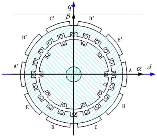
Figure 1.
Five-phase induction motor structural topology.
According to the extended Park transform, two orthogonal subspaces α1β10 and α3β30 and a zero-sequence component were obtained using Equation (1). The α1β10 subspace included the fundamental components, and α3β30 included the third-harmonic components [19,20,21,22]:
In order to reduce as much as possible the influence of magnetic field fluctuation on the induction motor performance, the ideal output voltage, as shown in Equation (3), was assumed to form an ideal circular magnetic field via the inverter:
This paper proposes an SVPWM algorithm that combines the adjustable variable ratio and the adjustable zero-vector action time to improve the DC-link utilization and realize harmonic suppression.
3. Analysis of a Space Voltage Vector Based on a Five-Phase Voltage Inverter
Figure 2 shows the structural topology of a five-phase voltage-source inverter driving induction motor.
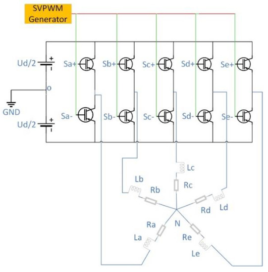
Figure 2.
Five-phase voltage source inverter structural topology.
The switch function S = [SA, SB, SC, SD, SE] is used to describe the working status of a voltage source inverter. S* is a Boolean variable (* = A, B, C, D, E); when S*+ = 1, the upper switch of the corresponding leg is on and the lower switch is off, and when S*+ = 0, the lower switch of the corresponding leg is on and the upper switch is off. According to Figure 2, the output phase voltage of the five-phase voltage source inverter can be expressed as U* = S*·UD, where UD denotes the DC-link voltage. Therefore, the output voltage space vector of a five-phase voltage source inverter can be expressed as shown in Equation (4):
When the switch function S has different values according to Equation (4), different output voltage vectors will be obtained, which can be divided into four categories according to their amplitude. There are 32 active vectors, including 10 large active vectors, 10 middle active vectors, 10 small active vectors, and 2 zero vectors, (U0 = 00000) and (U31 = 11111), which form a regular decagon with different side lengths, dividing the space into 10 sectors. Table 1 shows the amplitude of the four kinds of space vector.

Table 1.
Amplitude of the voltage vector for a five-phase inverter.
The voltage space vector distribution of a five-phase voltage-source inverter is given as shown in Figure 3 in the α1β1 space. The 5 bit binary corresponding to each voltage space vector indicates the switching state corresponding to the vector; for example, U25(11001) indicates the switch function S = [1,1,0,0,1], SA+ = 1, SB+ = 1, SC+ = 0, SD+ = 0, SE+ = 1, SA− = 0, SB− = 0, SC− = 1, SD− = 1, SE− = 0.
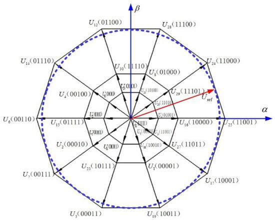
Figure 3.
Voltage vector distribution of a five-phase voltage source inverter.
4. Algorithm Analysis and Comparison
4.1. Traditional Last Four-Vector Algorithm
According to Figure 3, the nearest two-vector SVPWM algorithm (NTSVPWM), which is composed of two large vectors and two zero vectors adjacent to the reference vector, and the nearest four-vector SVPWM algorithm (NFSVPWM), which is composed of two large vectors, two medium vectors, and two zero vectors adjacent to the reference vector, are traditional algorithms used in the context of a five-phase motor based on the mature SVPWM symmetric modulation algorithm of the three-phase inverter.
When NTSVPWM is used, the maximum value of the reference voltage vector is the inscribed circle radius of the positive decagon, composed of the large vector in the linear modulation range, as shown in Equation (5). is the amplitude of the reference voltage. is the maximum amplitude of the reference voltage:
The modulation index of the voltage source inverter can be defined as in Equation (6):
The maximum linear modulation index, based on NTSVPWM, is shown in Equation (7):
Because of the two following reasons [1,20], although the modulation index m = 1.231 is greater than m = 1.1547 (modulation index of the three-phase motor in the line range), m = 1.231 does not become the boundary of the linear and overmodulation regions.
- (1)
- An independent generation of the output voltage in the n-phase VISs requires at least (n − 1) active voltage vectors, where n is the number of phases.
- (2)
- NTSVPWM is a simple extension of space vector modulation of three-phase VSIs, which leads to the generation of low-order output voltage harmonics of significant values.
The boundary of the linear and overmodulation regions of the five-phase induction motor is m = 1/cos(pi/(2 × 5)) = 1.0514, which comes from thee NFSVPWM algorithm, according to [23,24]. This means that the linear modulation region decreases as the number of phase n increases in the n-phase motor. Although this is a disadvantage, more space vectors and a lesser low-order harmonic influence make the multi-phase motor have better characteristics than the three-phase motor, including a five-phase induction motor.
Figure 4 shows a schematic diagram of any sector generating a reference voltage vector with NFSVPWM adopting a five-phase voltage source inverter.
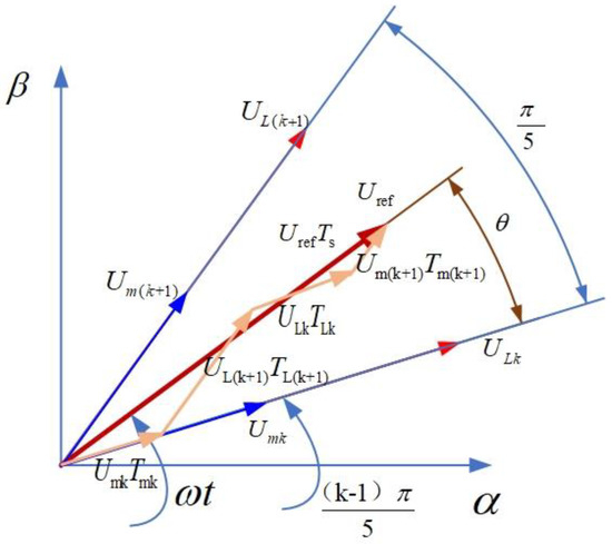
Figure 4.
Composition of a reference vector based on NFSVPWM (the Nearest Four-vector SVPWM algorithm) in sector k.
According to the volt-second balance principle of the space voltage vector and Figure 4, the vector equilibrium equation is presented as Equation (8):
where TLk, TL(k+1), and Tmk, Tm(k+1) are the large vector and middle vector action time in sector k; Ts is the PWM switching period; and T0 is the action time of the zero vector in one switching period.
When the ratio of the vector action time equals the ratio of the corresponding vector amplitude, as shown in Equation (9), the action time of the four vectors can be obtained as shown in Equations (10)–(14):
The modulation waveform of the symmetric modulation mode in the first sector, as shown in Figure 5, can be given, and the modulation waveforms in another sector can be obtained, which are not described here.
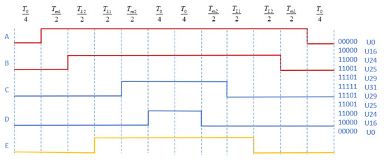
Figure 5.
Modulation waveforms in the first sector.
The maximum reference voltage based on NFSVPWM can be obtained as shown in Equation (15):
The corresponding modulation index can be obtained as shown in Equation (16):
According to Equations (7) and (16), NFSVPWM has a lower modulation index than NTSVPWM but better characteristics. When m ≤ 1.0514, either NTSVPWM or NFSVPWM can be used, but NFSVPWM is the best according to [22,23,24]. When 1.0514 < m ≤ 1.231, the NFSVPWM algorithm cannot be used because of the longer action time of the middle space vector. The aim of this paper was to propose a new method dynamic modulation four-vector algorithm to improve DC bus utilization and reduce the harmonics.
4.2. Dynamic Modulation Four-Vector Algorithm
According to Section 4.1, NFSVPWM results in the DC bus utilization being lower because of the low modulation index, and NTSVPWM uses two large vectors, which improves the DC bus utilization and obviously increases the harmonics. Therefore, this section proposes a four-vector SVPWM algorithm that combines the dynamic ratio changing space vector acting time and the adjustable zero-sequence acting time, which improves the utilization rate of the DC bus voltage and reduces the harmonics.
The specific implementation steps of the algorithm are as follows:
- (1)
- Define the action time ratio λ between the medium vector and the large vector.
- (2)
- According to the volt-second balance principle and Equation (8), compute the action time of the space vector to give Equations (17)–(20):
- (3)
- Determine the relationship between the parameter λ and the reference voltage Uref, which is shown as Equation (21):
According to Equation (21), when Ud is constant, the reference voltage changes with λ; the relationship is shown in Figure 6. When λ = 0, the maximum reference voltage can be obtained, which is 0.6472Ud, and the corresponding modulation index is m = 1.231, in which only the two adjacent larger vectors work. When λ = 0.618, the reference voltage is 0.5527Ud and the corresponding modulation index is m = 1.0514, which means the two adjacent large vectors and the two middle vectors work together.
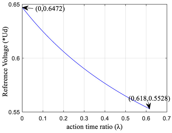
Figure 6.
The relationship between the reference voltage and λ.
Figure 7 shows the relationship between the modulation time and action time ratio λ when Ts = 10−4 s. When λ > 0.618, the reference voltage further decreases (m < 1.0514); the long action time of the middle vector causes the total action time to be greater than Ts, which not only reduces the affecting time to ensure the total action time is equal to Ts but also causes the lower DC bus voltage utilization rate and larger harmonics. When m < 1.0514, λ = 0.618 is used to make the best of the space vector.
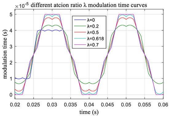
Figure 7.
The modulation time-based action time ratio λ.
- (4)
- Determine the relationship between action time ratio λ and the modulation index m to gain maximum utilization of the DC bus voltage, which is shown as Equation (22):
- (5)
- Zero-vector action time randomizationThe zero-vector action time randomization was proposed because the MMF (magneto motive force) depends on the five-phase voltage vector action time difference and has nothing with the conduction time of the voltage vector. Zero-vector action time randomization, which can adjust the electromagnetic compatibility without additional hardware, was used to spread the harmonics concentrated around certain frequencies to a wider frequency band and produce a more continuous and uniform power spectrum. In order to keep Teffect, as defined in Equation (23), as a constant and to reduce the harmonic effect, zero-vector action time randomization was introduced.In Sector 1, for example, the principle of zero vector randomization is shown in Figure 8. Figure 8a shows the PWM symmetric modulation waveform adopting the traditional four-vector method, wherein the action time of the two zero vectors is equal. Figure 8b shows the PWM random modulation waveform, wherein the action time of the two zero vectors is random.
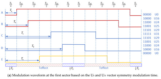
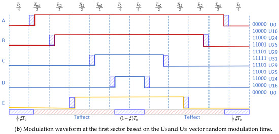 Figure 8. Random modulation waveforms of the first sector of a five-phase induction motor.
The effective action time of the corresponding half cycle can be expressed as Equation (23). The action time of the zero vector (U0 and U31) in the half cycle is shown by Equation (24):
5. Simulation and Experiments
5.1. Simulation
In order to test the proposed algorithm, a five-phase induction motor simulation model was built based on Matlab/Simulink, as shown in Figure 9. The simulation model mainly included a reference vector module, sector calculation module, action time module, PWM generator module, inverter module, and simulation load module. The motor parameters of the simulation model were consistent with the parameters of the actual induction motor as shown in Table 2. In order to verify the algorithm, two typical modulation indexes, m = 1.0514 and m = 1.1, were considered.
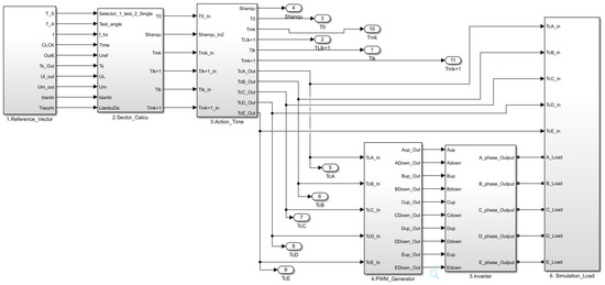
Figure 9.
Five-phase motor simulation model based on Matlab/Simulink.
Table 2.
Main parameters of the five-phase induction motor.
- (1)
- Reference-voltage module: This module was used to set the simulation parameters, such as the five-phase voltage, frequency, and modulation index, to compute the reference voltage.
- (2)
- Sector calculation module: This module was used to calculate the sector of the reference vector and the action time of the corresponding space vector.
- (3)
- Action time module: This module was used to determine the sequence of the space vector at every sector and the effect of moment of the space vector.
- (4)
- PWM generator module: This module was used to generate the PWM wave.
- (5)
- Inverter module: This module was used to simulate the characteristics of the five-phase voltage-source inverter.
- (6)
- Simulation-load module: This module was used to simulate the characteristics of the experimental induction motor.
When the modulation index m = 1.0514, the modulation time waveform curves were as shown in Figure 10. Figure 10a shows the NTSVPWM algorithm and Figure 10b shows the NFSVPWM algorithm. The corresponding voltage curve of each phase is shown in Figure 11; the output voltage of each phase was far less than the DC bus voltage and the maximum DC-bus utilization rate was not reached using NTSVPWM, as shown in Figure 11a, although the output voltage of each phase could reach the DC-bus voltage with a short modulation time using NFSVPWM, as shown in Figure 11b. The corresponding harmonic chart is shown in Figure 12. The third harmonic was 28.9% and the seventh harmonic was 4.66% for NTSVPWM, as shown in Figure 12a, which shows that the harmonic component was relatively large. The third harmonic was 0.28% and the seventh harmonic was 0.35% for NFSVPWM, as shown in Figure 12b.
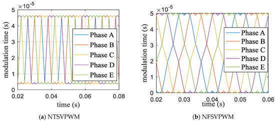
Figure 10.
Five-phase modulation time based on traditional algorithms.
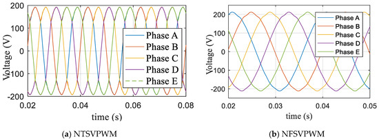
Figure 11.
Voltage waveforms based on traditional algorithms.
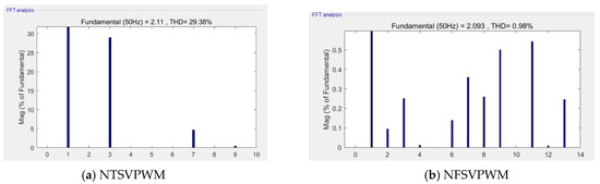
Figure 12.
Harmonic characteristics at m = 1.0514.
When the modulation index m = 1.0514, according to Equation (22), the modulation time ratio was the same as the amplitude ratio. Two large vectors, two middle vectors, and two zero vectors modulated dynamically. The corresponding modulation time waveform only phase A and phase C modulation time are shown in Figure 13. The corresponding output voltage of each phase is shown in Figure 14, where the output voltage reached the maximum DC bus utilization. Figure 15 shows the corresponding harmonics, where the third harmonic accounted for 0.21% and the seventh harmonic accounted for 0.25%. The third and seventh harmonics were reduced.
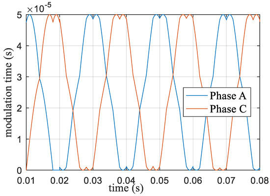
Figure 13.
Action time of the space vector voltage at m = 1.0514.
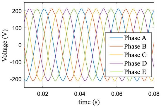
Figure 14.
Five-phase voltage based on the new algorithm at m = 1.0514.
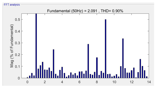
Figure 15.
Harmonic characteristics based on the new algorithm at m = 1.0514.
When the modulation index m = 1.1, the NTSVPWM and dynamic NFSVPWM with a symmetry zero vector were used to obtain the phase action time waveform, as shown in Figure 16. The corresponding output voltage is shown in Figure 17, and the corresponding harmonic characteristics are shown in Figure 18. The third harmonic accounted for 28.9%, and the seventh harmonic accounted for 4.66% for NTSVPWM as shown Figure 18a. The third harmonic accounted for 9.127%, and the seventh harmonic accounted for 1.215% for the dynamic NFSVPWM with a symmetry zero vector as shown Figure 18b.
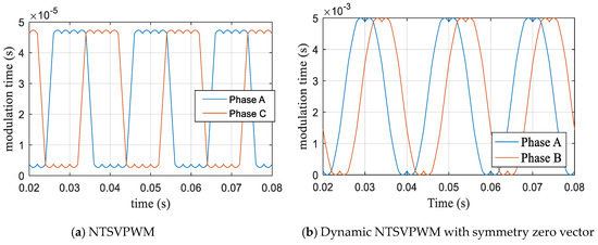
Figure 16.
Modulation time curve based on NTSVPWM at m = 1.1.
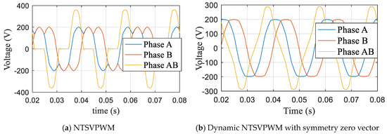
Figure 17.
A and B phase voltage at m = 1.1.
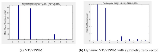
Figure 18.
Harmonic characteristics at m = 1.1.
When the modulation index m = 1.1, the action time ratio λ was determined according to Equation (22), and the modulation time curve was obtained as shown in Figure 19. The corresponding five-phase voltage and AB (AB = Phase A − Phased B) line voltage curves are shown in Figure 20, and the corresponding harmonic characteristics are shown in Figure 21. The third harmonic accounted for 8.9% and the seventh harmonic accounted for 1.2%.
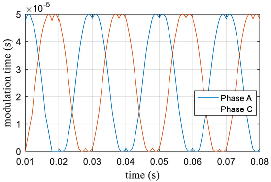
Figure 19.
Modulation time curve of the space vector voltage based on the new algorithm at m = 1.1.
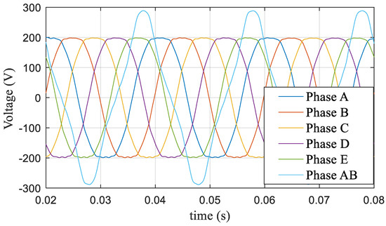
Figure 20.
Five-phase voltage and AB (AB = Phase A − Phase B) line voltage at m = 1.1.
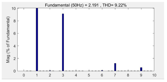
Figure 21.
Harmonic characteristics at m = 1.1.
The simulation showed that the proposed algorithm not only ensured that the DC-bus voltage utilization ratio remained in the maximum utilization state but also effectively reduced the influence of harmonics.
5.2. Experiments
In order to verify the proposed algorithm, a five-phase prototype system was supplied by an inverter composed of two three-phase two-level voltage-source inverters sharing the same DC-link voltage, with each inverter phase leg operating independently. A STM32F407 high-performance microcontroller was used to control the inverter. Figure 22 shows the experimental system of the five-phase induction motor.
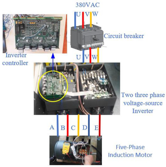
Figure 22.
Five-phase induction motor control principle.
The main parameters of the five-phase induction motor are shown in Table 2.
Figure 23 shows the some-phase PWM (Pulse Width Modulation) control waveform. The PWM frequency was 10 kHz in this experiment. When the electrical characteristics of the IGBT inverter were considered, a 5-us dead band was set taking into account the inverter manufacturer’s suggestion to form a complementary control waveform of the upper and lower bridge, thus avoiding inverter burn because the upper and lower bridge are connected at the same time. In order to avoid the influence of the dead band on the inverter output voltage, voltage feedback compensation was taken into account.
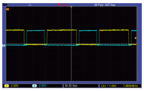
Figure 23.
PWM (Pulse Width Modulation) control waveform of phase A.
Figure 24 shows the experimental voltage waveform at m = 1.0514, when a traditional modulation strategy was used. Figure 25 shows the harmonic characteristics; the third harmonic accounted for 28.9%, and the seventh harmonic accounted for 4.66%, as shown in Figure 25a, for NTSVPWM. The third harmonic accounted for 0.27%, and the seventh harmonic accounted for 0.36%, as shown in Figure 25b, for NFSVPWM.
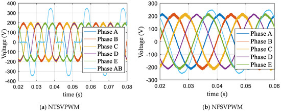
Figure 24.
Voltage waveform based on traditional modulation at m = 1.0514.
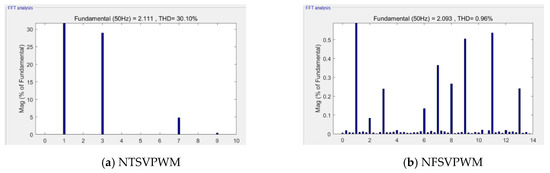
Figure 25.
Harmonic characteristics at m = 1.0514.
Figure 26 shows the experimental voltage waveform at m = 1.0514 when the dynamic modulation algorithm proposed in this paper was used. Figure 27 shows the harmonic characteristics, wherein the third harmonic accounted for 0.22%, and the seventh harmonic accounted for 0.25%.
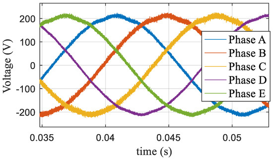
Figure 26.
Voltage waveform based on the dynamic modulation algorithm at m = 1.0514.
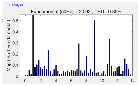
Figure 27.
Harmonic characteristics based on the dynamic modulation algorithm at m = 1.0514.
Figure 28 shows the experimental voltage waveform at m = 1.1, when the NTSVPWM and dynamic NFSVPWM with a symmetry zero vector were used. Figure 29 shows the harmonic characteristics. The third harmonic accounted for 28.93%, and the seventh harmonic accounted for 4.75% for NTSVPWM as shown Figure 29a. The third harmonic accounted for 9.13%, and the seventh harmonic accounted for 1.211% for the dynamic NFSVPWM with a symmetry zero vector as shown Figure 29b.
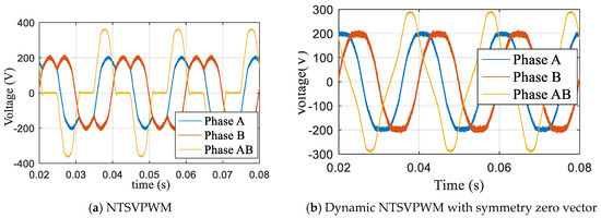
Figure 28.
Voltage waveform based on traditional modulation at m = 1.1.
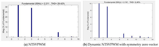
Figure 29.
Harmonic characteristics at m = 1.1.
Figure 30 shows the experimental voltage waveform at m = 1.1, at which the dynamic modulation algorithm proposed in this paper was used. Figure 31 shows the harmonic characteristics, wherein the third harmonic accounted for 8.9% and the seventh harmonic accounted for 1.4%.
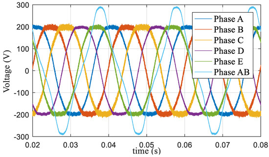
Figure 30.
Voltage waveform based on the proposed dynamic modulation algorithm at m = 1.1.
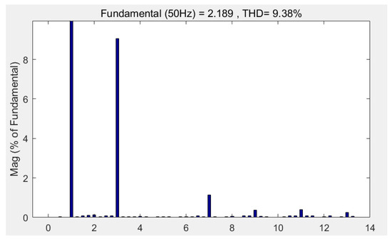
Figure 31.
Harmonic characteristics based on the proposed dynamic modulation algorithm at m = 1.1.
The experimental results showed that the proposed algorithm can improve DC-bus voltage utilization and effectively reduce the influence of harmonics.
5.3. Results Analysis
Based on the information provided in Section 5.1 and Section 5.2, Table 3 and Table 4 were compiled.
Table 3.
Simulation and experimental data for m = 1.0514.
Table 4.
Simulation and experimental data for m = 1.1.
- (1)
- When NTSVPWM is adopted, the lower-order harmonic is large and remains constant no matter how the modulation index ratio changes.
- (2)
- When m ≤ 1.0514, NFSVPWM and the proposed algorithm can be used because of the small harmonic. When m > 1.0514, the dynamic NFSVPWM with a symmetry zero vector can be used to improve the DC bus utilization and harmonic.
- (3)
- The proposed dynamic and adjustable new pattern four-vector SVPWM algorithm has better characteristics to improve DC-bus utilization and reduce the harmonic influence
6. Conclusions
The five-phase induction motor, as a typical multiphase motor, has its own advantages and applications in many fields. Based on systematic analysis of the existing SVPWM algorithm, this paper proposed a dynamic and adjustable new pattern four-vector SVPWM method. The algorithm uses the modulation index and zero vector to improve the characteristics of the inductor motor, the function relationship with real-time dynamic ratio between the action–time ratio of the space voltage vector and the modulation index was proposed to maximize DC bus utilization ratio, and the random zero-vector dynamic modulation mode was used to reduce the harmonic influence, being able to spread the harmonics concentrated around certain frequencies across a wider frequency band and thus produce a more continuous and uniform power spectrum.
A simulation model was developed using Matlab/Simulink and an experimental system was established based on an STM32 microprocessor and two three-phase voltage source inverters. When m ≤ 1.0514, NFSVPWM and the proposed algorithm can be used because of the small harmonic. When m > 1.0514, the proposed dynamic and adjustable new pattern four-vector SVPWM algorithm has better characteristics, which proved the feasibility and effectiveness of the proposed algorithm to improve DC-bus voltage utilization and reduce the harmonics.
Author Contributions
J.L. wrote the paper and performed the simulation and experimental work; D.M. contributed to providing materials/funding/analysis tools and supervised the paper. All authors have read and agreed to the published version of the manuscript.
Funding
This research received no external funding.
Conflicts of Interest
The authors declare no conflicts of interest.
References
- Levi, E. Multiphase electric machines for variable-speed applications. IEEE Trans. Ind. Electron. 2008, 55, 1893–1909. [Google Scholar] [CrossRef]
- Levi, E.; Bojoi, R.; Profumo, F.; Toliyat, H.A.; Williamson, S. Multiphase induction motor drives-a technology status review. IET Electr. Power Appl. 2007, 1, 489–516. [Google Scholar] [CrossRef]
- Subotic, I.; Bodo, N.; Levi, E.; Katic, V.A.; Dumnic, B.; Milicevic, D. Overview of fast on-board integrated battery chargers for electric vehicles based on multiphase machines and power electronics. IET Electr. Power Appl. 2016, 1, 217–229. [Google Scholar] [CrossRef]
- Singh, S.; Tiwari, A.N. Simulation and Comparison of SPWM and SVPWM Control for Two Level Inverter. In Proceedings of the First International Conference on Smart Technologies in Computer and Communication, Rajasthan, India, 27–29 March 2017. [Google Scholar]
- Kumar, K.V.; Michael, P.A.; John, J.P.; Kumar, S.S. Simulation and Comparison of SPWM and SVPWM Control for Three Phase Inverter. Arpn. J. Eng. Appl. Sci. 2010, 10, 61–74. [Google Scholar]
- Lakhdari, L.; Bouchiba, B.; Bechar, M. Comparative Analysis of SVPWM and the Standard PWM Technique for Three Level Diode Clamped Inverter fed Induction Motor. Int. J. Electr. Comput. Eng. 2018, 12, 102–108. [Google Scholar]
- Show, S.K.; Parthiban, P. Analysis of current controlled voltage source Inverter with Space Vector PWM and Sinusoidal PWM techniques. In Proceedings of the International Conference on Innovations in Information, Embedded and Communication Systems, Coimbatore, India, 19–20 March 2015. [Google Scholar]
- Tang, X.; Lai, C.; Liu, Z.; Zhang, M. A svpwm to Eliminate Common-Mode Voltage for Multilevel Inverters. Energies 2017, 10, 715. [Google Scholar] [CrossRef]
- Chen, X.-Z.; Yu, Z.-P. SVPWM Modulation Algorithms in Motor Controller of Electric Vehicles. J. Tongji Univ. (Nat. Sci.) 2017, 45, 92–97. [Google Scholar]
- Gao, H.-W.; Yang, G.-J.; Liu, J. SVPWM algorithm for five-phase voltage source inverter based on modulation functions. Electr. Mach. Control. 2014, 18, 56–61. [Google Scholar]
- Yu, F.; Zhang, X.; Qiao, M. Multi-phase Carrier PWM Control Technology Based on Zero-Sequence Signal Injection. Trans. China Electrotech. Soc. 2009, 24, 127–131. [Google Scholar]
- Liu, H.; Yu, H.; Sun, L. Modulation Strategy to Reduce Common-Mode Voltage for Three-to-Five Phase Indirect Matrix Converter. In Proceedings of the International Conference on Intelligent Computing for Sustainable Energy and Environment, Shanghai, China, 12–13 September 2012; pp. 28–36. [Google Scholar]
- Pradeepa, S.; Surrendra Kumar, P.; Prakash, G. Adoption of SVPWM Technique to CSI and VSI. In Proceedings of the 2018 3rd International Conference for Convergence in Technology, Pune, India, 6–8 April 2018. [Google Scholar]
- Janaki, R.V.; Keerthipati, S. An improved SVPWM control technique to reduce winding losses of 9-phase induction motor. In Proceedings of the 2019 IEEE Region 10 Conference, Kochi, India, 17–20 October 2019. [Google Scholar]
- Biswas, J.; Nair, M.D.; Gopinath, V.; Barai, M. An optimized hybrid SVPWM strategy based on multiple division of active vector time (MDAVT). IEEE Trans. Power Electron. 2017, 32, 4607–4618. [Google Scholar] [CrossRef]
- Muthukumar, P.; Melba, P.; Jeevananthan, S. An Improved Hybrid Space Vector PWM Technique for IM Drives. Circuits Syst. 2016, 7, 2120–2131. [Google Scholar] [CrossRef]
- Hannan, M.A.; Ali, J.A.; Mohamed, A.; Uddin, M.N. A Random Forest Regression Based Space Vector PWM Inverter Controller for the Induction Motor Drive. IEEE Trans. Ind. Electron. 2017, 64, 2689–2699. [Google Scholar] [CrossRef]
- Zhu, L.; Bu, F.; Huang, W.; Pu, T. Non-Sinusoidal Dual Random Space Vector Pulse Width Modulation Strategy for Five-Phase Inverter. Trans. China Electrotech. Soc. 2018, 33, 4824–4833. [Google Scholar]
- Karampuri, R.; Prieto, J.; Barrero, F.; Jain, S. Extension of the DTC technique to multiphase induction motor drives using any odd number of phases. In Proceedings of the 2014 IEEE Vehicle Power and Propulsion Conference (VPPC), Coimbra, Portugal, 27–30 October 2014; pp. 1–6. [Google Scholar]
- Lewicki, A.; Strankowski, P.; Morawiec, M.; Guzinski, J. Optimized Space Vector Modulation Strategy for Five Phase Voltage Source Inverter with Third Harmonic Injection. In Proceedings of the 19th European Conference on Power Electronics and Applications, Warsaw, Poland, 11–14 September 2017. [Google Scholar]
- Tang, J.; Wang, T.; Cui, S. Implementation Method of SVPWM for Five-Phase Inverters. Trans. China Electrotech. Soc. 2013, 28, 64–72. [Google Scholar]
- Ryu, H.-M.; Kim, J.-H.; Sul, S.-K. Analysis of Multiphase Space Vector Pulse-Width Modulation Based on Multiple d-q Spaces Concept. IEEE Trans. Power Electron. 2005, 20, 1364–1371. [Google Scholar] [CrossRef]
- Prieto, J.; Barrero, F.; Durán, M.J.; Marín, S.T.; Perales, M.A. SVM Procedure for n-Phase VSI with Low Harmonic Distortion in the Overmodulation Region. IEEE Trans. Ind. Electron. 2014, 61, 92–97. [Google Scholar] [CrossRef]
- Halasz, S. Overmodulation Region of Multi-phase inverters. In Proceedings of the 13th International Power Electronics and Motion Control Conference, Poznan, Poland, 1–3 September 2008. [Google Scholar]


© 2020 by the authors. Licensee MDPI, Basel, Switzerland. This article is an open access article distributed under the terms and conditions of the Creative Commons Attribution (CC BY) license (http://creativecommons.org/licenses/by/4.0/).