Abstract
Thermal conductivity, hydraulics properties and potential use in low-enthalpy geothermal applications of single and double U geothermal probes enhanced with carbon fibre are discussed in this work. Although the efficiency of a shallow geothermal installation is chiefly based on chemical and physical characteristics of rocks and hydrogeological aspects of the subsurface, the total heat extracted from the subsoil also depends on the intrinsic thermal characteristics of probes. New configurations and solutions aimed at enhancing the performance of components are therefore of considerable interest in this field of research. As a consequence of the economic and versatility advantages of the components, geothermal probes have been generally developed with materials like polyethylene, which presents, however, isolating behaviour that does not allow ideal heat exchange in ground source heat pump systems (GSHP). Innovative combinations of different materials are therefore necessary in order to improve thermal conductivity and to preserve the exceptional workability and commercial advantages of the finest elements available on the market. This work presents results coming from experimental tests involving standard polyethylene geothermal probes integrated with radial rings of polyacrylonitrile-based carbon fibre (PAN). Our evaluations are aimed at finding the best solutions for thermal exchange and adaptability with respect to traditional systems. Hydraulic and thermal performances and the response in a geo-exchange system have been verified. The new solutions appear to be highly suitable as geothermal exchangers in shallow geothermal systems and contribute to significantly reduce the total costs pertaining to the drilling operations.
1. Introduction
Within the current global energy context, the constant increase in energy demand leads to a redefinition of the energy supply models [1,2]. In this respect, innovative forms of exploitation like low temperature geothermal applications find an ideal condition for growth. Although the direct use of heat has found exploitation in many countries, current technologies regarding the implementation of innovative materials for heat exchange are scarcely investigated and consequently with limited development [3]. Shallow geothermal systems (SGS) are suitable in subsoils with normal thermal gradients. The thermal energy stored in the shallowest portion of the Earth’s crust (100–150 m depth) is very high, since the soil temperature remains constant throughout the year with values comparable with the average annual temperatures at the surface depending on the latitude [1,3]. This paradoxically represents an optimal condition for the supply of thermal energy through the use of heat exchanger systems with open or closed-loop configurations [3]. Although geothermal probes are essential components of SGS, standard materials do not allow at present an optimal heat exchange between the soil and the system. Significant thermal dissipation occurs between the soil, the bentonitic grout as filler and the heat exchanger, which finally causes reduction in performances of the entire system. This means that higher performances of the whole SGS installation can be only accomplished if characteristics of each of the above-mentioned components turns out to be enhanced. Applied research in this direction has been conducted especially in regards to the bentonitic grout [4,5] and thermo-vector fluids [6,7], producing encouraging results for what concerns the final heat output of the system. Experimentation of new materials for improving the characteristics of standard geothermal probes has been extremely limited throughout recent years.
Polyethylene is currently used in the production of low enthalpy geothermal probes (DIN 8074 standard) [8,9]. Polyethylene has completely replaced metallic materials such as copper and stainless steel used in past installations, which, although characterized by high thermal conductivity, have shown technical problems of a different nature (for example, stray currents, corrosion) coupled with expensive production costs [3,10]. As a matter of fact, polyethylene is a polymer, with good chemical-physical properties (chemical composition, thermal expansion, flexural strength, compressive strength, etc.) and limited production costs. In this regard, all properties of polyethylene such as ductility, flexibility, transportability on site, workability and easy installation make it the best compromise in terms of quality/cost ratio for any type of SGS [10,11]. However, polyethylene exhibits very low thermal conductivity between 0.40 and 0.45 W/mK. Being basically a thermal insulator, it can be considered scarcely adequate for heat exchange purposes [12,13].
Research of new solutions capable of improving the heat exchange performances of SGS also regarding the probes, moved our point of view towards polyethylene materials doped with carbon fibre (CF) in order to produce hybridized geothermal probes [14,15]. Indeed, CF is a material characterized by exceptional mechanical properties and high thermal conductivity (~14 W/mK) [16,17,18]. The hybridization of polyethylene probes with CF would therefore allow a significant increase of the thermo-mechanical performances of the geo-exchange system.
The analysed data are aimed at finding an optimal configuration to enhance both hydraulic and thermal properties of this new probe type. These improvements make the hybridized probes highly suitable for their use as efficient components in geothermal installations, reaching on the whole better economic competitiveness than standard materials on the market [4].
2. Materials and Methods
The experimental idea comes from the observation of multiple limitations due to materials currently used in SGS. For this reason, the use of alternative and innovative composite materials like polymeric ones hybridized with CF has been taken into account [10,19]. CF has peculiar physical and mechanical characteristics that, properly applied on a polymeric material such as for example polyethylene, allows significantly increasing the thermo-mechanical performance of the geo-exchange system. The exclusive use of CF for the construction of the geothermal probes cannot be considered as a realistic solution, since the required economic investment would be too expensive and cannot be compensated even considering the significant benefit in terms of thermal conductivity and heat exchange. In addition, the CF pipes can be only made of rods, as the finished product is absolutely rigid and consequently lacking in flexibility, and also with a limited length (6 m–max value), implying the use of hydraulic joints and not allowing easy procedures during transport and movements in the installation site.
The research in testing a new composite product combining good physical-mechanical characteristics of polyethylene and high thermal conductivity of CF has been finalized with the aim of revisiting the classic single and double U geothermal probes [15,20,21]. Although the polyethylene geothermal probes show good mechanical properties, contained costs, portability and easy work operations on site, they have intrinsic low thermal properties (thermal conductivity, power of extraction). Since polyethylene does not appear as the optimal material for heat exchange in the subsoil, the identification of materials with higher thermal conductivity (>1 W/mK) can represent a turning point in the primary exchange in SGS. CF was taken into consideration for designing such new components [22]. It is necessary to specify that the CF products display several configurations depending on the manufacturing process for its production. To date, most CF applications are generally obtained from polyacrylonitrile-based carbon fibre (that is, PAN, produced by modifications of organic acrylonitrile fibres, such as Toho Tenax HTS40) [16], which is much less expensive and with good heat transmission (thermal conductivity of about 16–20 W/mK) [17,23] compared to CF production obtained from viscoelastic polymer composed of aromatic hydrocarbons (that is, PITCH, produced from tar residue-Dialed K13916) [24,25], which shows higher mechanical properties, much higher manufacturing costs and considerable thermal conductivity (200 W/mK) [18,26,27].
Although thermal conductivity of the PITCH fibre is elevated, it is not fully exploitable since the thermal exchange between the probe–cement system and the subsoil occurs at low or very low temperatures. In fact, the high thermal conductivity properties could cause pronounced thermal dissipative phenomena. However, if we consider that the “hybrid” probe is characterized by small and localized thermally improved exchange surface, what has been previously supposed could be completely limited by the facts.
Concerning the investigation of innovative setup solutions, various tests were carried out to verify the best configuration for the implementation of more conductive materials and subsequently to prove the hydraulic seal conditions and the thermal properties of a prototype system. Firstly, an experimental test for the longitudinal application has been carried out on polyethylene pipe samples (PN16) with diameter of 32 mm, thickness of 3 mm and length of 3 m. The application consists of 3 CF coatings on the outer surface of the polyethylene pipe, staggered from each other by 120 degrees and equipped with a width of 1 cm and thickness of 1.5 mm for the total length of the probe. The implementation of each coating occurs by overlapping the fibre layers through interweaving of fibre and resin filaments until the desired thickness is obtained. Some critical issues arose by using this configuration, such as the internal micro-deformations on its external surface due to the straightening process of reel winding, and excessive cost due to massive quantities of CF treatment.
Another configuration, aimed at applying the CF radially on the probe, has been therefore tested as a more suitable solution. Using an appropriate experimental equipment available at the EarTherm Laboratory (Figure 1a), a series of grooves with constant section (width of 1 cm and depth of 1.5 mm) have been carried on the circumference of the 3-m-long polyethylene pipe. These grooves have been then filled with CF. Two different layouts have been developed: (1) a first configuration, based on 5 radial grooves coated with CF, with a defined distance of 50 cm (I50); and (2) a second setting based on 3 radial grooves coated with the same CF material, with a defined distance of 80 cm (I80) (Figure 1b).
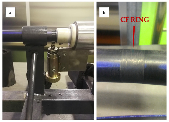
Figure 1.
(a) Production of the innovative probes with radial carbon fibre (CF) rings and (b) finishing of the radial CF rings.
As required by the testing protocols [8,28], specific water tightness tests were carried out on the probe. This procedure consists in filling the probe circuit using water or air systems to specific operating pressures of 5–6 bars [8,28]. The minimum duration of the test is 1 h, while the pressure variation tolerance is around 0.2–0.5 bars. The test circuit consists of a PN 16 polyethylene sample tube with a diameter of 32 mm and a length of 3 m, accompanied by 5 CF rings 2 cm wide, radially arranged and spaced 50 cm steps from each other (I50). The ends of the tube were connected respectively to a mains water point and a pressure gauge to control the pressure variations (Figure 2).

Figure 2.
“Sausage effect” during the pressurization hydraulic test.
Once the hydraulic testing phase of the hybridized probes has been completed, a second phase of thermal conductivity tests was performed to compare the heat exchange performances of the hybrid CF-polyethylene (I50–I80) and standard-polyethylene probes (ST). The comparison test was carried out between three reference samples: (1) commercial probe in polyethylene Ø 32 mm with a thickness of 3 mm and a length of 2.80 m (ST); (2) a hybrid probe with the main core in polyethylene Ø 32 mm and application of 3 CF rings of constant section (width = 1 cm; thickness = 1.2 mm) radially displaced and spaced at 80 cm steps for the whole length (2.80 m) (I80); and (3) a hybrid probe with the main core in polyethylene Ø 32 mm and application of 5 CF rings of constant section (width = 1 cm; thickness = 1.2 mm) radially displaced and spaced 50 cm step for the whole length (2.80 m) (I50) (Figure 3). Each probe has been equipped with bends at 90 degrees in order to both facilitate the filling of the water inside the circuit and to prepare two water temperature measuring detectors inside the circuit (S1 and S2 in Figure 3a). For the entire length of the pipe (excluding a length of 30 cm on each side), an electrically operated heating cable (heat output of 49 W/m, 58.7 °C maximum temperature) has been joined and clamped (Figure 3b). To ensure a good contact of the heating cable arranged along a rectilinear direction on the surface of the pipe, an adequate number of clamps has been used, arranged and spaced from each other with a pitch of about 6 cm. Each sample, after an internal cleaning (jets of water and then dried with compressed air), has been almost completely filled with 1.6 litres of main supply water. The thermal test has been carried out in a static fluid regime to determine the heat exchange occurring only through conduction. The test is divided into three steps: (1) heating phase to verify the response times of the thermal conductivities during the transmission of heat by conduction; (2) cooling phase to evaluate the thermal dispersion by conduction; and (3) heating/cooling phase in order to determine the possible effect of thermal inertias.
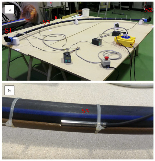
Figure 3.
(a) Setup of the thermal test for the hybrid polyethylene probe and (b) detail of the temperature detection system S3 and heating cable component.
The study of an innovative heat exchange material has allowed to develop geo-exchange prototype systems useful to reproduce, at a small scale, the heat exchange taking place between the elements of a geo-exchange system: subsoil–concrete/grout–probe [29,30]. Firstly, two cylindrical systems 1.05 m height were built and “U” type geothermal probes have been embedded inside them. In particular, the first system has been assembled using a standard polyethylene probe cemented within a pre-mixed commercial grout (Figure 4a), while the second system has been built using a radial I50 probe fixed inside hybridized bentonite grout (1.5% of graphite additive) (Figure 4b) according to the optimal heat exchange properties analysed by [4]. In both cases, the filling and the complete maturation of the grout (28 days) within suitable PVC moulds (diameter of 200 mm) took place. After the maturation and drying phase, the two cement-probe columns were inserted inside the tubes with a heating cable (Figure 4c). The empty space between the column and the tube containing the heating cable (equal to 5.5 cm per side) was completely filled with soil, which represents the transmission and propagation source of the heat. Furthermore, the top of the column was also covered with a thickness of 5 cm of soil. During the test, the soil thermal inertia variation could be attenuated (constant temperature of 17 °C) by calibrating the heating cable operation range (turning off temperature = 17.2 °C, starting temperature = 16.9 °C). The two different configurations (standard and innovative) were analysed through a thermal test in no water condition (Figure 5a), static water regime (Figure 5b) and dynamic regime (Figure 5c). Through three temperature probes, the temperature variation was recorded: S3 was placed at 21 cm of depth inside the soil (Figure 5), and S1 and S2 were placed to respectively measure the inlet and outlet temperatures of the fluid inside the probe (Figure 5).
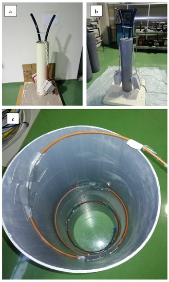
Figure 4.
(a) Preparation of the standard system for the thermal response test; (b) preparation of the innovative system for the thermal response test; and (c) heating cable configuration.
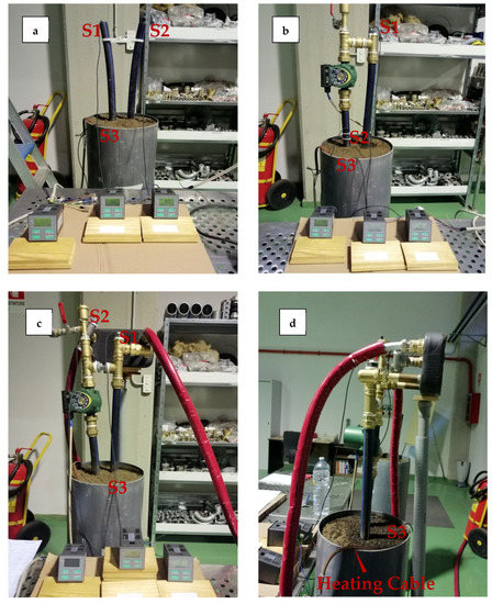
Figure 5.
Geo-exchange prototype configuration: (a) no-water and static initial condition; (b) dynamic regime test; (c) primary and secondary circuit configuration; and (d) details of the supplementary double circuit device.
Moreover, to evaluate and verify the different behaviours of the 2 cement-probe systems in a real configuration setup, an additional heat exchange element (plate heat exchanger) equipped with 2 independent circuits was considered. A primary circuit consisting of a closed loop system connected to the probe and a secondary circuit was made up of an open water loop network (Figure 5c,d). The primary circuit operation and the secondary circuit activation may cause considerable change in the recorded temperatures of S1 (inside the geothermal probe) and S2 (heat exchanger IN) probes (Figure 5c, Table 1).

Table 1.
Experimental data resulting from tests on the geo-exchange prototype system.
3. Results
3.1. Hydraulic Conditions
The test circuit consists of a PN 16 polyethylene sample tube with diameter of 32 mm and length of 3 m, accompanied by 5 CF rings 2 cm wide, radially arranged and spaced at steps of 50 cm from each other (Figure 2). The test started at a pressure of 5.2 bars. After 2 h a value of 28 bars was fixed and mantained up to 24 h (much longer duration than the time required for the test validation protocol [8,28]). At the end of the test, a pressure of 50 bars was established to evaluate and avoid the possible presence of micro-leaks in the circuit. No leaks, deformations, cracks, fractures or signs of weakening in the piping system were detected up to a maximum pressure of 50 bars (sausage effect shown in Figure 2).
3.2. Standard vs. Innovative Probe Thermal Response
Results of thermal tests on the standard and innovative probes are reported in Figure 6. The experimental temperature values were measured at three different steps: heating–cooling and heating/cooling phases for each studied system (that is, ST, I50 and I80). Each testing phase displays marked differences between standard and innovative probes (Figure 6).
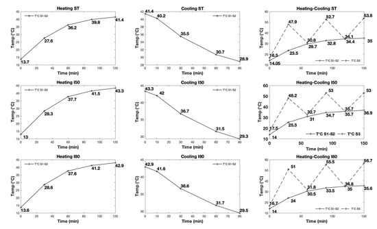
Figure 6.
Results of the thermal test in standard (ST) and innovative probes (I50–I80): heating step, cooling step, heating-cooling step.
Tests performed during the heating phase (heating cable starting temperature of 17.2 °C and maximum temperature reached of 58.7 °C) confirm the net change in temperature between the standard and both hybrid probes. As a matter of fact, the water temperature at the end of the test for the I80 hybrid probe has a surplus of 1.6 °C if compared to the ST probe, while the I50 hybrid probe shows a surplus value of 2.6 °C (Figure 6). Furthermore, although the I50 shows a lower starting water temperature (13 °C), after the first half hour of the test it shows higher temperature values. This is clearly evidenced also after an hour of testing, since the gap between the water temperature of the I80 and I50 hybrid systems turns out to be already canceled; the 0–60 min time range of the I50 hybrid probe displays a thermal output of 0.9 °C, higher than the ST system and 0.1 °C higher than the I80 configuration.
Although the I50 and I80 configurations allow better heat exchange during the heating phase, they show lower perfomances during the cooling phase (heating cable turned off). After 80 min, the water temperature decreased only by 12.5 °C for the ST configuration, while probes with innovative components I50 and I80 produced 14 °C and 13.4 °C temperature decreases, respectively. It is worth noting that the CF rings negatively affect the entire cooling process in a way that the heat exchange during the first heating phase was favoured by the high thermal conductivity of CF, but this caused pronounced heat dissipation during the cooling phase.
In order to define the behaviour of innovative materials with alternating heat exchange processes over a short period of time, data from heat and cooling alternation heat exchange tests have been acquired (S3 temperature values; Figure 6). The obtained results illustrate higher values of heat exchange for both hybrid probe systems (I50, I80). In particular, the water temperature (S1–S2 measure) in the I80 hybrid system (measured at the end of the test) displays a surplus of 0.6 °C compared to the ST configuration, while the water temperature of the I50 layout shows a surplus of 1.9 °C (Figure 6).
3.3. Geo-Exchange Prototype System
Data from the experimental results conducted for both standard (commercial material) and innovative (I50 CF probe and doped grout) geo-exchange prototype systems are reported in Figure 7. Among the main analysed aspects, the measure of the soil temperature as a function of time has been taken into specific consideration (temperature detector S3). Since the initial test conditions of standard probe and commercial grout vs. innovative probe and doped grout apparatuses are identical, the different behaviour can be related principally to the new composite materials of the I50 probe system. Three different conditions have been analysed (Figure 5a–c).
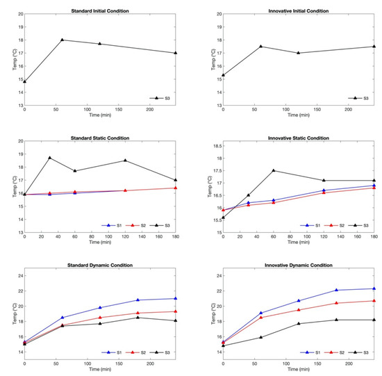
Figure 7.
Results of thermal test in standard (ST) and innovative geo-heat exchanger prototype (I50): standard initial condition, static condition, dynamic condition. Values were recorded every 5 min, although graphs show values at 30, 60, 120, 180, and 240 min for convenience.
The initial no-water condition (initial condition graph in Figure 7) allows evaluating the effects of thermal inertia of the soil. Observing the S3 temperature during the whole testing time, the temperature values of innovative system rise up to 17.5 °C, but they do not reach the value of 18 °C found in the standard system. Indeed, the ground is able to transfer heat more effectively with the cement-probe innovative system.
The presence of water (1.6 litres of main water that fills geothermal heat exchangers) allows observing the heat exchange in static water conditions of the two geo-exchange systems, simply by the record of the temperature of the water (at rest) inside the probes S1 and S2 (Figure 5a). As for the previous no-water condition, a maximum temperature value of 18.7 °C was recorded in the S3 sensor due to thermal inertia for the standard ST system, since the ground is unable to optimally exchange heat with the standard cement-probe system and tends therefore to accumulate and transmit it slower. Concerning the innovative system, the maximum temperature of 17.5 °C has been observed in S3. In addition, temperature values observed in S1 further highlight the goodness of the heat exchange of this hybrid geo-exchange system (16.9 °C at the end of the test) compared to the standard one (16.4 °C at the end of the test). Figure 8 shows the S1 values detected in both systems (hybrid and innovative) in order to proceed with a direct comparison of the values obtained. Two substantial differences have been recognized: (1) the standard system shows an increase from the initial value of 0.5 °C at the end of the initial condition test; and (2) the hybrid system illustrates an increase of 1 °C at the end of the test.
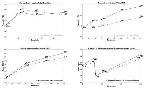
Figure 8.
Standard (ST) and innovative (I) systems during the initial, static, dynamic and primary-secondary circuits tests.
Unlike the static water testing phase, during the dynamic tests the thermal geo-exchange was influenced by both processes of heat transmission through conduction and by significant convection phenomena [3]. The amount of the exchanged heat by convection per time unit depends on several aspects. Among these, the most important are: the difference in temperature between the walls of the probe and the fluid, the exchange surfaces, the fluid’s velocity (the higher the fluid velocity the higher is the molecules movement and maximum amount of heat absorbed by the fluid) [3], the convective exchange coefficient of the wall and fluid. For this type of test, a substantial difference is given by the positioning of probes S1, S2, S3 (Figure 5b). Observing the values of temperature in the standard system (cement-polyethylene probe), the maximum value of 18.5 °C was reached in the S3 probe. However, after an hour, the attained value of 17.4 °C confirms the hypothesis that heat exchange with the ground is limited in the standard system, so it tends to store heat (in an hour the soil increased its temperature by 2.4 °C).
The S2 temperature in standard configuration shows a total increase of 4.1 °C compared to the initial test measurement. On the other hand, the hybrid cement-probe system shows a different behaviour. The S2 temperature values display an increase of 5.5 °C compared to the initial value: this illustrates a total surplus of 1.4 °C compared to the standard cement-probe system after the first hour of testing (Figure 7).
Figure 8 shows the S1 values detected in both systems (hybrid and innovative) in order to proceed with a direct comparison of the values obtained. As shown in the Figure 8, the two systems, despite starting from the same initial value, show two different behaviours. The standard system displays an increase of 3.2 °C after 1 h, 4.5 °C after 2 h, 5.5 °C after 3 h and 5.7 °C at the end of the test compared to the initial status. On the other hand, the hybrid system shows an increase of 3.8 °C after 1 h, of 5.4 °C after 2 h, of 6.8 °C after 3 h and 7 °C at the end of the test compared to the starting temperature. As a result, the hybrid system allows a better and more efficient heat exchange with the subsoil, providing 1.3 °C water temperature more than a standard system and with a temperature difference always present at any phase of the test.
3.4. Primary and Secondary Circuit
In order to evaluate and verify the different behaviour of the 2 cement-probe systems in a real configuration setup, an additional heat exchange element (plate heat exchanger) equipped with 2 independent circuits was considered. A primary circuit consists of a closed loop system connected to the probe, whereas a secondary circuit is made up of an open water loop network where, at the end of the heat exchange, the water is consumed (Figure 5c,d). During the test the temperature probes position is important in order to determine the temperature before and after the exchange between the two circuits. Figure 5c,d shows that the S1 recorder is positioned inside the geothermal probe in order to obtain the soil-probe heat exchange temperature; the S2 probe is placed at the inlet of the heat exchanger in order to measure the probe-mains water temperature heat exchange.
The S3 probe is placed at a depth of 21 cm to measure the temperature of the ground heated by the cable (Figure 5c,d). As a result of the activation of the secondary circuit after the primary circuit operations (previous test parameters), there is a considerable change in temperatures recorded in the S1 and S2 probes, caused by the mains water which has a lower temperature (11–11.3 °C).
The temperature variations are due to thermal exchange between the primary and secondary system; a significant decrease in the temperature of the heat transfer fluid and an increase in the water temperature of the secondary circuit was observed (Figure 9).
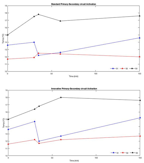
Figure 9.
S1, S2 and S3 measurements in standard and innovative configuration during the primary-secondary circuits tests.
In fact, according to the first principle of thermodynamics, heat moves spontaneously from the hottest fluid to the colder fluid until a certain equilibrium temperature is reached [3]. As a matter of fact, once equilibrium is reached, the temperature is not the same for both fluids (constant temperatures over time). The test has a total duration of 150 min: during the first 30 min the primary circuit was activated, while the secondary circuit was activated only from 30 to 60 min; during the last 90 min, only the primary circuit was operating. Considering the standard system, it is possible to observe that during the operation of the primary circuit (after the first 30 min), the recorded temperature in S1 (temperature of the water circulating inside the geothermal probe) increases by 0.4 °C compared to the starting temperature value. However, after the activation of the secondary circuit (temperature of inlet mains water = 11.3 °C), the temperature decreases by about 1.8 °C in approximately 5 min. During the simultaneous running of the 2 circuits, S1 increases its temperature by 0.4 °C. Finally, after the disconnection of the secondary circuit (60 min), the S1 temperature reaches the value of 14.6 °C at the end of the test (150 min), 2.0 °C higher than the previous value. On the other hand, the temperature recorded in the S2 probe increases when the secondary circuit is opened. This is probably due to the presence of air bubbles in the system or to a higher temperature of the intake water. Concerning the hybrid cement-probe system, S1 values during the first 30 min of the test (operation of primary circuit only) display an increase of 0.9 °C with respect to the initial value. However, after the activation of the secondary circuit (inlet of mains water temperature = 11 °C), the temperature decreases by 2.7 °C in only 5 min. During the work of both circuits, the S1 increases its temperature by 0.7 °C. Finally, after the disconnection of the secondary circuit (60 min), the S1 temperature reaches the value of 15.2 °C at the end of the test (2.5 °C higher than the initiaal condition). In particular, a temperature of 13.7 °C has been recorded in S1, that is, the system supplied an increase of 1 °C to the geo-probe water after just 15 min (Table 1). With respect to the S2 temperature values, these also changed during the primary circuit operation phase, and this is due to the constant presence of water inside the exchanger circuit. With respect to the S2 values, the first 30 min of the test show a 0.6 °C increase in the S2 detector. After the activation of the secondary circuit, the temperature value of S2 drops by 0.5 °C due to the mains water (11 °C). After 60 min, S2 registers a 0.5 °C temperature increase. Finally, after the disconnection of the secondary circuit the system reaches a temperature of 12.7 °C (during the last 90 min), 0.5 °C more than the previous value.
4. Discussion
The importance of increased thermal efficiency and using unconventional materials useful for their implementation in a probe system prototype were investigated in this study.
The configuration of CF rings added to a standard polyethylene probe affects not only the thermal exchange but also the hydraulic properties of the final product. Concerning the hydraulic characteristic of the studied probes, pumping gradually until the pressure of 28 bars starting from the initial pressure of 5.2 bars and maintaining the whole circuit pressurized for about 2 h did not produce either any significant sign of deformation (swelling) nor of failure (Figure 1). Although the circuit has been subjected to progressive pressurization up to 50 bars, the pipe connections showed significant resistance. However, the section between the CF rings showed evident swelling (sausage effect), preserving the initial section in correspondence with the CF rings. Given that a standard polyethylene probe would have already exhibited permanent deformations under these conditions (maximum expected operating pressure of 16 bars [7]), the high breaking resistance of an experimental probe is instead attributable to the presence of the CF coating rings which, sufficiently spaced from each other, have divided the overall length of the polyethylene pipe into shorter segments and almost doubled the probe’s operating pressure. Looking at thermal tests carried out on the geothermal probe system, a significant difference between the standard probe’s material and both innovative setups, I50 and I80, can be observed (Figure 4). Application of CF in the radial direction increased the thermal output of the probes. In particular, as evidenced in Figure 10, the thermal output of probes varies according to the distance where different CF rings are placed. During the heating phase, the I80 probe shows a thermal output higher than 3.62% with respect to the ST probe, while the I50 probe shows an increase of 4.6% with respect to the ST probe. Under alternating heating/cooling phases, the I80 probe shows an increase of 1.7% compared to the standard probe, while the I50 probe has thermal output higher than 5.4% (Figure 10). Application of CF in the radial direction (I50) is therefore the best configuration in terms of thermal output under multiple test conditions. For these reasons, this configuration has been used for assembling a prototype geothermal well undergoing other thermal tests. Considering the performances relative to the optimal thermal properties in additivities grout materials [6] and according to the previous thermal analysis on hybrid polyethylene probes, the thermal response tests were realized taking into consideration a prototype consisting of bentonite material with additives of pure graphite at 1.5% and hybridized geothermal probes with I50 configuration, compared to a prototype in standard grout material and geothermal probes in standard polyethylene. Results in Figure 11 show that during the heating step of the test, doped materials such as cement with 1.5% pure graphite and the CF-I50 probe allowed an increase in heat exchange of about 3% compared to the standard one. In the test with running water, the heat transfer increase is even sharper and reaches a value of 6%. The results show that, even in the case of water at rest, the hybrid system allows a more effective heat exchange, compared to the standard system. In addition, the hybrid system allows a better and more effective heat exchange with the subsoil in dynamic condition, providing the water 1.3 °C more than a standard system and with a temperature variation evidenced at any point of the test. To constrain the heat transfer values in a real heat exchange system, a device consisting of a plate heat exchanger has been inserted into the prototype system. The primary circuit, linked directly with the probe fluid, and a secondary open circuit linked to the main water has been considered. Figure 5 shows the main components of the standard and innovative configuration heat exchange systems. Although starting from the same initial value, the advanced system provides a higher water temperature than the standard system after the first phase of the test (first 30 min). After the activation of the secondary circuit, the heat fluid of the I50 configuration probe undergoes a greater drop in temperature due to the entry of cold mains water (I50 prototype = 12 °C, ST prototype = 12.2 °C), but is able to reach a higher temperature at the end of the test (I50 prototype = 15.2 °C, ST prototype = 14.6 °C). Results confirm the idea of a non-optimal exchange of the soil in the ST configuration, since it tends to accumulate heat and gradually transmit it. Considering the hybrid probe system, the 15.2 °C recorded values in the S1 probe show an optimum heat exchange. This means that the hybrid system allows an effective heat exchange. Considerably increased output temperatures define a 4% improvement of the thermal exchange compared to the standard system (ST probe + grout) (Figure 11).
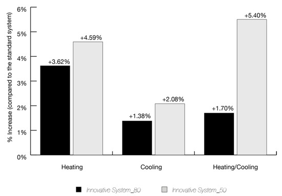
Figure 10.
Thermal exchange increase between CF-I80 and CF-I50 composite probe for heating, cooling and heating/cooling thermal tests.
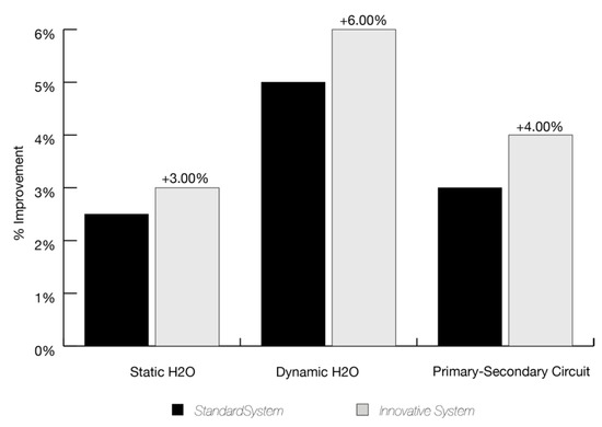
Figure 11.
Thermal exchange increasing comparison between standard and innovative geo-heat exchange prototype for static, dynamic and primary/secondary tests.
Considering the subsoil as an unlimited heat accumulation reservoir, dissimilar conductivity values between the constructive elements of a shallow geothermal system (soil-grout-probe interaction) result in a thermal output limitation. Assuming the grout and probe materials as two resistors placed in series, a simplified evaluation can be obtained by calculating the total heat output through the thermal analogy between Fourier’s Law with the electrical conduction of Ohm’s Law [3,31]. According to thermal conductivity computation through a planar interface (values close to cylindrical surface approximation), thermal resistances (Rb) for each element can be obtained from the following equation:
where Rb is the thermal equivalent resistance expressed in K/W, ΔT is the minimum temperature difference required for heat exchange expressed in K and q is the rate of heat transfer in W. Assuming a conventional setting of the thermal exchange system (that is, geometry of the probe pipes, borehole and probe diameters) for both the ST and I50 configurations, results presented in this work put into evidence the effect of the changing thermal conductivity of innovative probe (λI50) in the computation of Rb. Considering that [31]:
where Rp is the total thermal resistance of the probe and Rgr is the thermal resistance of the sealing grout (that is, pipe/ground interface), both expressed in m K/W; Lp and Lgr refer to the thickness of probe and grout respectively; Ap and Agr refer to the area perpendicular to heat flow (in m2) for the probe and grout respectively, and they are obtained from the relation 2πrh, where r is the probe and grout radius (m), h is the depth (m); λgr is the thermal conductivity of the grout and λp the thermal conductivity of the probe.
A simplified calculation can be obtained by fixing a minimum temperature difference required for standard heat exchange of 279.15 K (ΔT). In this regard, a total thermal exchange (q) of 9.2 kW is obtained from equation (1) for the ST configuration. For what concerns the I50 configuration, an average λpI50 has been calculated with a simple weighted average of the thermal conductivities of each part constituting the hybrid probe (standard polyethylene plus CF rings), together with a λgrI50 for a doped bentonite taken from [4]. In doing this, a value of ~19 kW of exchanged heat has been calculated by using the innovative compound materials. Changes of λp from λpST = 0.45 W/mK to λpI50 = 1.3 W/mK, along with changes of λgr from λgrST = 1.9 W/mK to λgrI50 = 2.2 W/mK, produce increasing of the total heat output approximately twice.
The decreasing of the equivalent thermal resistance Rb due to the increase of thermal exchange have important effects on the configuration of the SGS system. Indeed, considering a borehole 125-m-long and with diameter of 180 mm, a total length reduction of 37.5 m (ca. 30%) is obtained by using the innovative I50 pipe system without any heat output decreasing. This implies that the larger the sizing of the closed-loop system results in a higher economic benefit due to reduction of the total borehole length or of the total number of probes to be installed. All these benefits result in a significant economic savings for the whole drilling operations, due to savings from the amount of grout in order to fill the borehole, the costs associated with the probes and, finally, for the correct sizing of the heat pumps.
5. Conclusions
In this work, the thermal characteristics of new configuration geothermal probes have been analysed with the aim of creating an innovative setup useful for geothermal applications. The experimentation is aimed at producing hybrid probes with CF radial rings used in a small real geothermal prototype. The development of prototypes using innovative configurations, such as composite CF-polyethylene probes has allowed obtaining configurations with an optimal thermal output compared to standard polyethylene probes currently used in the geothermal energy market. Results put into evidence good perspectives for their possible use in real closed loop geothermal installations with massive advantages in terms of probes length optimization and economic savings. In addition, through an adequate engineering process involving industrial production on a large scale, these materials could replace components currently used for the installation of SGS, improving their thermal performances. Concerning the innovative CF use, the radial implementation of CF rings allows suitable production cost and commercial distribution. Indeed, raw materials could be obtained from secondary industrial recycle processes, like recycled CFs from scraps of virgin fibre processing or recovery from discarded material. Therefore, the re-processing of waste, will be introduced again into the production cycle for creation of new products like geothermal probes in a circular economic model. For this reason, the cost/benefit ratio of experimental products could be very competitive. Importance of such experimental research consists in finding innovative materials and configurations that are able to create a foundation for the future perspectives of composite materials for geo-heat conduction and to make low enthalpy geothermal applications more competitive in the renewable energy market.
Author Contributions
G.F. and M.V. conceived and drafted the work; G.F., M.V., F.B., S.I. and G.M.B. conceived and designed the experiments; F.B., S.I. and G.M.B. performed the experiments and G.F. analysed the data. M.V. gave the final approval of the version to be published. All authors have read and agreed to the published version of the manuscript.
Funding
This work was supported by the funding program PIACERI 2020-22 of the University of Catania (project code 22722132140; principal investigator M.V.).
Institutional Review Board Statement
Not applicable.
Informed Consent Statement
Not applicable.
Acknowledgments
The authors are grateful to the staff of EarTherm laboratories for providing an opportunity to design and build the innovative solutions and for recording the thermal data of the heat-exchange systems.
Conflicts of Interest
The authors declare no conflict of interest.
References
- Midttømme, K.; Banks, D. Ground-source heat pumps and underground thermal energy storage: Energy for the future. NGU Spec. Publ. 2008, 11, 93–98. [Google Scholar]
- Floridia, G.; Viccaro, M. Geological field investigation for the assessment of the low-grade geothermal resources from volcanic terrains of the Island of Salina (Aeolian Islands, Italy). Earth Environ. Sci. 2019, 367, 012007. [Google Scholar] [CrossRef]
- Banks, D. An introduction to “thermogeology” and the exploitation of ground source heat. Q. J. Eng. Geol. Hydrogeol. 2009, 42, 283–293. [Google Scholar] [CrossRef]
- Viccaro, M. Doped bentonitic grouts for implementing performances of low-enthalpy geothermal systems. Geotherm. Energy 2018, 6. [Google Scholar] [CrossRef]
- Blázquez, C.S.; Martín, A.F.; Nieto, I.M.; García, P.C.; Sánchez Pérez, L.S.; González-Aguilera, D. Analysis and study of different grouting materials in vertical geothermal closed-loop systems. Renew. Energy 2017, 114, 1189–1200. [Google Scholar] [CrossRef]
- Riahi, A.; Damjanac, B.; Moncarz, P. Innovative Closed-Loop Geothermal Well Designs Using Water and Super Critical Carbon Dioxide as Working Fluids. In Proceedings of the Forty-Second Workshop on Geothermal Reservoir Engineering, Stanford, CA, USA, 13–15 February 2017. [Google Scholar]
- Badache, M.; Eslami-Nejad, P.; Bastani, A.; Aidoun, Z.; Nguyen, A. Theoretical and experimental analysis of a vertical direct expansion geothermal evaporator using CO2 as refrigerant. Sci. Technol. Built Environ. 2019, 25, 1081–1094. [Google Scholar] [CrossRef]
- Ground Source Heat Pump Association. Closed-Loop Vertical Borehole Design, Installation & Materials Standards; Ground Source Heat Pump Association: Milton Keynes, UK, 2011; pp. 1–45. [Google Scholar]
- Kavanaugh, S.P.; Rafferty, K. Ground-Source Heat Pumps, Design of Geothermal Systems for Commercial and Institutional Buildings; ASHRAE: Atlanta, GA, USA, 1997. [Google Scholar]
- Stober, I.; Bucher, K. Geothermal Probes. In Geothermal Energy: From Theoretical Models to Exploration and Development; Springer: Berlin/Heidelberg, Germany, 2013; pp. 65–113. ISBN 978-3-642-13352-7. [Google Scholar]
- Vasile, C.; Pascu, M. Practical Guide to Polyethylene; Smithers Rapra Publishing: Shawbury, UK, 2005. [Google Scholar]
- Abesser, C. Open-Loop Ground Source Heat Pumps and the Groundwater Systems: A Literature Review of Current Applications, Regulations and Problems; British Geological Survey Nottingham: Nottingham, UK, 2010. [Google Scholar]
- Ball, D.A.; Fischer, R.; Talbert, S.G.; Hodgtt, D.; Aurer, F. State-of-the-art survey of existing knowledge for the design of ground-source heat pump system. NASA STI/Recon Technical Report N 1983, 84, 16504. [Google Scholar]
- Badenes, B.; Sanner, B.; Mateo Pla, M.Á.; Cuevas, J.M.; Bartoli, F.; Ciardelli, F.; González, R.M.; Ghafar, A.N.; Fontana, P.; Lemus Zuñiga, L.; et al. Development of advanced materials guided by numerical simulations to improve performance and cost-efficiency of borehole heat exchangers (BHEs). Energy 2020, 201. [Google Scholar] [CrossRef]
- Mendrinos, D.; Katsantonis, S.; Karytsas, C. Review of Alternative Pipe Materials for Exploiting Shallow Geothermal Energy. Innov. Corros. Mater. Sci. 2017, 7, 13–29. [Google Scholar] [CrossRef]
- Bhatt, P.; Goe, A. Carbon Fibres: Production, Properties and Potential Use. Mater. Sci. Res. India 2017, 14, 52–57. [Google Scholar] [CrossRef]
- Katzman, H.A.; Adams, P.M.; Le, T.D.; Hemminger, C.S. Characterization of low thermal conductivity pan-based carbon fibers. Carbon 1994, 32, 379–391. [Google Scholar] [CrossRef]
- El-Hage, Y.; Hind, S.; Robitaille, F. Thermal conductivity of textile reinforcements for composites. J. Text. Fibrous Mater. 2018, 1. [Google Scholar] [CrossRef]
- Mendrinos, D.; Katsantonis, S.; Karytsas, C. Pipe materials for borehole heat exchangers. In Proceedings of the European Geothermal Congress 2016, Strasbourg, France, 19–24 September 2016; pp. 19–24. [Google Scholar]
- McCray, K. Guidelines for the Construction of Vertical Boreholes for Closed Loop Heat Pump Systems; National Ground Water Association: Westerville, OH, USA, 1997. [Google Scholar]
- Roumeli, E.; Markoulis, A.; Kyratsi, T.; Bikiaris, D.; Chrissafis, K. Carbon nanotube-reinforced crosslinked polyethylene pipes for geothermal applications: From synthesis to decomposition using analytical pyrolysis-GC/MS and thermogravimetric analysis. Polym. Degrad. Stab. 2014, 100, 42–53. [Google Scholar] [CrossRef]
- Ma, H.; Xu, F.; Zhou, Z.; Xu, W.; Ren, F. Polymer Composites with Enhanced Thermal Conductivity and Mechanical Properties for Geothermal Heat Pump Pipes. Polym. Polym. Compos. 2018, 26, 251–258. [Google Scholar] [CrossRef]
- Hatta, I.; Yamane, T.; Katayama, S.; Todoki, M. The Measurements of Thermal Conductivity of Carbon Fibers. J. Wide Bandgap Mater. 2000, 7, 294–305. [Google Scholar] [CrossRef]
- Kim, J.; Im, U.-S.; Lee, B.; Peck, D.-H.; Yoon, S.-H.; Jung, D.-H. Pitch-based carbon fibers from coal tar or petroleum residue under the same processing condition. Carbon Lett. 2016, 19, 72–78. [Google Scholar] [CrossRef]
- Yang, K.S.; Choi, Y.O.; Kim, Y.M.; Park, S.H.; Yang, C.M.; Kim, Y.J.; Soh, S.Y. Preparations of carbon fibers from precursor pitches synthesized with coal tar or petroleum residue oil. Fibers Polym. 2000, 1, 97–102. [Google Scholar] [CrossRef]
- Naslain, R. Carbon Fibers From Pan and Pitch. In Advanced Inorganic Fibers: Process—Structure—Properties—Applications; Wallenberger, F.T., Naslain, R., Macchesney, J.B., Ackler, H.D., Wallenberger, F.T., Eds.; Springer: Boston, MA, USA, 2000; pp. 233–264. ISBN 978-1-4419-8722-8. [Google Scholar]
- Inagaki, M. (Ed.) Chapter 4—Carbon Fibers. In New Carbons—Control of Structure and Functions; Elsevier Science: Oxford, UK, 2000; pp. 82–123. ISBN 978-0-08-043713-2. [Google Scholar]
- International Ground Source Heat Pump Association. Standards Committee Closed-Loop/Geothermal Heat Pump Systems. In Design and Installation Standards; International Ground Source Heat Pump Association: Stillwater, OK, USA, 2016. [Google Scholar]
- Wang, S.; Jian, L.; Shu, Z.; Chen, S.; Chen, L. A High Thermal Conductivity Cement for Geothermal Exploitation Application. Nat. Resour. Res. 2020, 29, 3675–3687. [Google Scholar] [CrossRef]
- Shonder, J.A. A New Method to Determine the Thermal Properties of Soil Formations from In Situ Field Tests; Oak Ridge National Laboratory: Oak Ridge, TN, USA, 2000.
- Remund, C.P. Borehole Thermal Resistance: Laboratory and Field Studies; ASHRAE Transactions: Atlanta, GA, USA, 1999. [Google Scholar]


Publisher’s Note: MDPI stays neutral with regard to jurisdictional claims in published maps and institutional affiliations. |
© 2020 by the authors. Licensee MDPI, Basel, Switzerland. This article is an open access article distributed under the terms and conditions of the Creative Commons Attribution (CC BY) license (http://creativecommons.org/licenses/by/4.0/).