Abstract
Extruded high-voltage direct current cable systems transmit electric power over long distances. Numerical field simulation can provide access to the internal electrothermal behavior of cable joints, which interconnect cable sections. However, coupled nonlinear electrothermal field simulations are still a challenge. In this work, a robust numerical solution approach is implemented and validated. This approach allows for efficient parameter studies of resistively graded high-voltage direct current cable joint designs. It is assessed how the dielectric stress distribution between the conductor connection and the grounded cable sheath is influenced by nonlinear field and temperature dependent electric conductivity of the field grading material. Optimal field grading material parameters, which fulfill the field grading and power loss requirements, are suggested based on the simulation studies.
Keywords:
HVDC; power cables; joints; field grading; nonlinear electrothermal coupling; multiphysics 1. Introduction
For the ongoing green energy transition, underground high-voltage direct current (HVDC) cable systems are deployed instead of overhead transmission lines. These systems require reduced space and, therefore, lead to a higher acceptance of the public [1,2,3]. The extruded, i.e., plastic-insulated, cable system technology enables long-distance underground power transport through densely populated or environmentally sensitive areas. Therefore, buried power transmission systems require extraordinary long life time, reliability, and resilience against adverse operation conditions. For example, the 525 kV direct current (DC) cable system SuedOstLink will install approximately 1000 km of extruded underground cables in Germany [4]. Several hundred cable joints are required to connect the cable sections, as the length of each cable section is a few km. There is a general consensus that the cable joints are the most vulnerable part of such systems [1,2,3,5]. A failure of a single joint leads to a significant downtime of the complete HVDC link. Hence, even a small failure probability for an individual cable joint leads to an unacceptable failure rate of the entire system. Cable joints interconnect cable sections, which are limited to few kilometers each. A cable joint requires field grading between the conductor connection and the grounded cable sheath in order to limit the dielectric stress. For high-voltage alternating current (HVAC) technologies, field grading design concepts are well established. However, these concepts cannot be transferred easily to the DC case. Thus, further research on field grading is required to adapt and develop concepts such as resistive field grading with field grading material (FGM) layers. These materials feature a field and temperature dependent conductivity to balance the electric field stress inside the joint. Furthermore, the introduction of HVDC cable systems for voltage levels above 320 kV provokes research efforts to better understand their behavior, improve the designs and to, finally, formulate standards [1]. While AC cable systems have been standardized for voltages up to 550 kV for more than 20 years in the highest voltage levels [6] and even longer for low and medium voltage applications [7], HVDC cable systems have only recently been standardized for voltages up to 320 kV [8]. All HVDC cable systems for higher voltage levels are still tested with procedures recommended in a technical report of the Cigré Working Group B1.32 [9].
Numerical simulation allows for an efficient characterization and optimization of cable joint designs. At the same time, they reduce costly experimental investigations in the high-voltage (HV) laboratory [10,11]. Field simulation offers the possibility to adequately resolve the electrothermal field phenomena of HV equipment in space and time (see e.g., [12,13,14]). Different studies were dedicated to HVDC cables and their nonlinear behavior [15,16,17,18,19,20]. Several authors outlined the modeling and simulation of HV cable joints [21,22]. Only a few systematic investigations have been carried out so far on the nonlinear field-controlling behavior of HVDC cable joints [23,24,25]. The strongly field and temperature dependent electric conductivity of the FGM exacerbates the numerical simulation of these joints (see, e.g., [5,25]).
To date, the following key performance parameters of cable joints have been formulated [1,5,16]:
- Electrical, thermal, and mechanical stability for all operating conditions including transient overvoltages,
- Minimal Joule losses and thus minimal heat production in the insulation material,
- Lifetime of several decades with an uncritical aging behavior.
This paper contributes to a deeper understanding of cable accessories by simulating the nonlinear electrothermal behavior of a resistively graded HVDC cable joint. A fast electrothermal field solver allows for studying the influence of the joint’s design parameters on the key performance criteria. The paper is structured as follows: First, the field grading principles and the investigated cable joint model are introduced. Second, the electrothermal problem is defined and the numerical solution approach is presented. Third, the result section comprises a validation of the simulation tool, and presents a study on selected joint parameters. It will be shown that the field strength along the stressed joint-cable interface must be carefully balanced. Furthermore, the effects on power dissipation and operating temperature inside the joint’s functional material must be taken into account.
2. Electric Field Grading and Cable Joint Model
Cable joint designs rely upon the principle of electric field grading, i.e., balancing the electric field stress at all points in the insulation such that a critical field stress is not exceeded [1,26]. Without suitable field grading measures, a joint is prone to internal electric or thermal failure. The bulk insulation fails if the electric field exceeds the dielectric breakdown strength of the material. Even more critical are interfaces of insulating materials subjected to tangential field stress, as they are electrically weak [27]. Therefore, the interface between the cable insulation and the insulating material of the joint body has to be designed carefully [28,29]. Additionally, cable joints may fail for reasons related to on-site installation, as there is the risk of incorrect assembly or contamination [30]. Furthermore, for HVDC applications, extruded cable accessories require dedicated electric field grading concepts. Field inversion and possible charge accumulation eventually caused by nonlinear conductivities must be avoided. Most probably, a combination of resistive and geometrical grading will be necessary, i.e., the resistive grading covering the continuous DC operating stress, and the geometric grading controlling transient stresses from overvoltages during lightning strikes or switching operations [1,2]. The resistive field grading in continuous DC operation is realized by adopting a FGM layer. An insulating material, such as silicone rubber, serves as matrix material. To achieve the desired nonlinear behavior, fillers with a strongly nonlinear electric conductivity, such as microvaristors, are added to the bulk material. The resulting compound material is called FGM. By diligently mixing the bulk matrix and filling materials, tailored field grading behavior can be realized [1]. An FGM layer is, then, placed at the interface of the cable’s and the joint’s insulation materials to balance the tangential field stress. Furthermore, the introduction of a FGM layer decouples the electric field distribution in the internal cross-linked polyethylene (XLPE) cable insulation layer and the insulation material of the joint. As negative side effect, the conductivity of the FGM is temperature dependent, which introduces Joule losses. These may threaten the thermal stability of the joint. On the long timescale, increased temperature stress in the joint may cause aging of the insulation materials and, thus, premature failure of the insulation.
Figure 1 shows a schematic of the investigated HVDC cable joint in an axisymmetric coordinate system, . The different materials are indicated by numbers in the figure. The two copper conductors (domain 1 in Figure 1) are connected with an aluminum connector (domain 2). Both, conductor and connector, are covered by a layer of conductive silicone rubber (domain 3). These domains (1–3) are assumed as perfect electric conductors in the simulation. The cable insulation consists of XLPE (domain 4) and the joint insulation of an insulating silicone rubber (domain 5). Both insulation layers are separated by a nonlinear resistive FGM (domain 6). The outer sheaths of the cable (domain 7) and the joint (domain 8) are made of conductive silicone rubber, which is connected to ground potential. The dash-dotted lines indicate the two-dimensional (2D)-axisymmetry along the z-axis and the reflection-symmetry along the -plane. Additionally, the conductive materials are highlighted in grey, the insulating materials in blue and the nonlinear FGM in yellow. The red line marks the evaluation path of the quantities of interest in the section below.
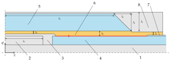
Figure 1.
Schematic of the investigated HVDC joint in the -z-plane (adapted from [24,26], drawing is not to scale). The colors indicate conductive materials (grey), insulating materials (blue) and the FGM material layer (yellow). The red line shows the evaluation path for quantities of interest, such as the tangential electric field strength, m. The numbers indicate the different materials as described in the text.
The joint is located 2 m below the surface (ambient temperature 20 °C). An additional base layer of sand is assumed with a thickness of 30 cm. The material characteristics and dimensions are summarized in Table 1. In this work, the nonlinear conductivity of the FGM is described by the analytical function proposed in [24]. The field and temperature dependent electric conductivity reads,
where and T denote the electric field strength in V/m and the temperature in K, respectively. The parameters, provided by the High-Voltage Laboratory of Technical University of Darmstadt, are , , V/m, V/m, and K. The field and temperature dependence of the conductivity in the range of interest for steady state operation is shown in Figure 2. The conductivity increases with rising temperature T. In the case of an overvoltage stress, the FGM becomes conductive. This operating range is not shown in the figure. The field and temperature dependence of the FGM clearly dominates the electrothermal behavior of the HVDC joint model. Other material characteristics, e.g., of the XLPE insulation material, are known to be less nonlinear and, therefore, are not considered in this paper [1,31].

Table 1.
HVDC cable joint model parameters, total length 1400 mm.
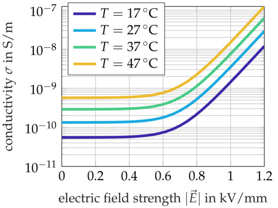
Figure 2.
Nonlinear field and temperature dependent conductivity of the FGM near the switching field strength . The FGM conductivity is described by (1).
The 2D-axisymmetric FE joint model is excited by the DC operating voltage of 320 kV. In the simulation, this excitation voltage is applied at the boundary of the conductive silicone rubber (domain 3 in Figure 1). The outer sheath of the cable (domain 7) and the joint (domain 8) are grounded. In the following, the maximum permissible temperature at the inner conductor (domain 1) during continuous operation is chosen to 90 °C according to the standard [8].
3. Electrothermal Problem Formulation
In continuous power grid operation, a HVDC cable system is in an electrothermal steady state, which is reached after several days of continuous DC operation (see e.g., [2,5]). This paper focuses on the analysis of nonlinear resistive field grading measures with FGM layers in steady state operation. The electrothermal problem is governed by the combination of the stationary current equation and the heat conduction equation,
which are coupled along the Joule losses and the temperature dependence of the electric conductivity, , and the thermal conductivity, . Herein, is the electric scalar potential, and T is the temperature. The steady state temperature of the conductor is almost completely determined by the Joule losses in the conductor itself. Because the electric potential and the temperature are almost constant in the conductor, the conductor is not considered in the joint model. Instead, its potential and its temperature are applied as electric and isothermal boundary conditions to the conductor-joint interface. Accordingly, the right-hand side of (3) only contains the Joule losses of the insulating and field grading materials.
Both field equations are discretized in an axisymmetric setting using nodal FE shape functions :
where and are the degrees of freedom for the electric scalar potential and the temperature, respectively. The FE procedure leads to the coupled system of equations
where follows from discretizing (2), whereas and follow from discretizing (3). The field dependencies of the losses and the material parameters constitute the coupling between (2) and (3).
The strong nonlinearity and the extreme variations in the electric conductivities of the different materials complicate the numerical solution of the electrothermal problem. An outer iteration is set up between (2) and (3). In each step, the relevant fields are updated and the system matrices and right-hand side are calculated anew. The thermal subproblem is solved within any further inner iteration, which means that the temperature distribution of the previous outer iteration determines the thermal conductivity . This is motivated by the fact that the temperature differences are comparably modest. The nonlinearity of the stationary current subproblem, however, needs to be resolved in each outer iteration step. Moreover, a simple successive substitution algorithm does not converge. Therefore, as a next iterate, is assembled using the newly obtained degrees of freedom and the previous iterate . Not until a relaxation factor, , below is selected, convergence is assured. The outer iteration starts with a thermal solution and takes two to three steps to convergence. In each outer iteration step, 30–50 damped iterations of the stationary current subproblem are needed. The implementation is carried out in the in-house MPI-parallel FE simulation tool Ksolv [14]. The Ksolv simulation tool is in the following referred to as HVDC solver. The simulation time is in the range of several seconds for a model with approximately degrees of freedom.
4. Simulation Results
4.1. Validation and Steady State Operation
For the numerical validation of the proposed solution scheme, a steady state simulation of the joint model is compared with the simulation results from [24]. For the validation study, a conductor temperature of 60 °C is assumed. Figure 3a shows the tangential electric field distribution and Figure 3b the temperature distribution along the interface between XLPE and FGM, i.e., the red line indicated in Figure 1. A perfect agreement of the result simulated with the HVDC solver and the reference simulation of [24], which was computed with COMSOL Multiphysics®, is obtained.
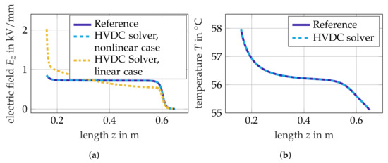
Figure 3.
Fields at the interface between XLPE and FGM in continuous operation, : (a) Tangential electric field strength ; (b) temperature T. The figures compare the simulation results obtained by the HVDC solver (dashed line) and a COMSOL reference simulation (solid line) assuming nonlinear FGM material properties, i.e., . Furthermore, the electric fields are compared to the linear, i.e., S/m, case (yellow dashed line). The evaluation path originates at the conductive silicone rubber sheath of the conductor joint (see red line in Figure 1).
Figure 4a shows the potential distribution, and Figure 4b shows the electric field strength distribution in the cable and the joint insulation material. The nonlinear conductivity of the FGM balances the electric field stress inside the FGM. Furthermore, the tangential field strength along the insulating material interface is balanced and the field stress peaks are more than halved compared to the linear case (see Figure 3a). High field strengths in the range of several kV/mm are observed in the insulating XLPE material of the cable and in the silicone material of the joint. The FGM layer decouples the stresses in the insulation material of the cable and the joint body effectively (see Figure 5). Inside the FGM, maximum field stresses occur at the triple points (see indicated positions in Figure 4b), i.e., the contact points of FGM, insulating material and conductive silicone rubber.
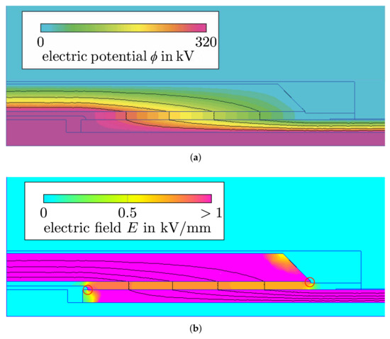
Figure 4.
Field distributions in continuous operation, : (a) Potential distribution and (b) electric field strength distribution inside the 2D cross-section of the HVDC cable joint. Equipotential lines are accentuated in black. The resistively graded joint is in steady state operation. The DC high voltage excitation is applied at the conductive silicone that covers the connection of the conductors and at the conductor. Ground potential is applied at the outer conductor of the cable sheath and the outer surface of the joint. Without suitable field grading measures, the material interfaces at the positions indicated by red circular markers would be affected by excessive electric field stress (compare Figure 3).
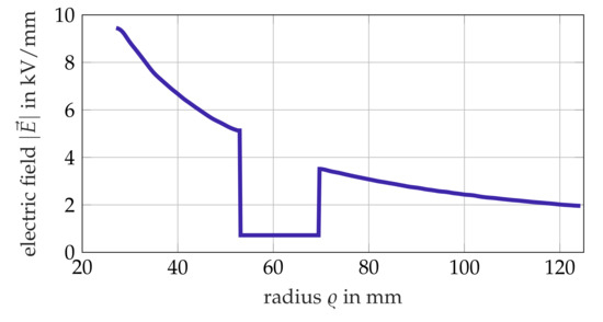
Figure 5.
Radial distribution of the electric field strength, , in kV/mm evaluated at the fixed position m which corresponds to the center of the evaluation path.
The simulation tool allows to study the joint subjected to various operating temperatures (see Table 2). A conductor temperature of 70 °C (normal operation) and 90 °C (temperature limit) is assumed. The surface temperature of the ambient earth is varied from 0 up to 40 °C. The quantities of interest are the mean and maximum tangential electric field strength components, , at the insulation interface (see evaluation path in Figure 1). As Table 2 shows, the mean and maximum electric fields are not significantly affected by the investigated temperature scenarios. Thus, a FGM with the chosen conductivity parameters fulfills the field grading requirements for a wide range of operating temperatures. However, the downside of this property is an increase of the power losses within the FGM by 40% from scenario (1) to (3) and by more than factor 2 from scenario (1) to (4), respectively. Therefore, the fgm performance must be regarded as sensitive to the operating temperature.
Table 2.
Simulated temperature scenarios.
4.2. Optimization of Field Grading Material Layer
An optimal FGM layer smooths out the electrothermal stress along the interface and, in particular, clips field stress peaks at the conductor side. As side effect, the Joule losses arising in the FGM are minimized. Furthermore, the operating temperature stays below a critical temperature such that none of the materials is harmed, and thus lies between 70–90 °C. The simulation tool allows for an investigation of the field grading performance of the FGM layer. Therefore, the FGM material characteristics are varied and the influence on the joint’s key performance parameters is studied. Two temperature scenarios are investigated. First, the inner conductor temperature is set to the value that is obtained for regular continuous operation with DC excitation voltage and rated current, i.e., 70 °C. Second, a worst case scenario with a conductor temperature of 90 °C is simulated. Both scenarios showed qualitatively comparable results. Therefore, the following discussion is restricted to the results assuming a conductor temperature of 90 °C. The influence of the material parameters , , and of the conductivity function (1) is investigated. The obtained field solution is assessed based on the following quantities of interest:
- Maximal tangential electric field strength along the interface between XLPE and FGM (see Figure 1);
- Electric losses inside the FGM;
- Mean and maximum temperature, , inside the FGM.
4.2.1. Base Conductivity
The base conductivity, , in (1) is the dominant conductivity during stationary operation. In the literature, is recommended to ensure decoupling between the insulating layers [23]. Herein, is the largest conductivity of the insulating materials, which is S/m in this model. This lower boundary can be confirmed based on the DC simulation results. A smaller conductivity causes an uneven electric stress distribution along the interface and, thus, increases the peak stress (see Figure 6a). Figure 6b shows the maximum tangential field strength with respect to the base conductivity. A field stress minimum is obtained for a base conductivity of S/m.
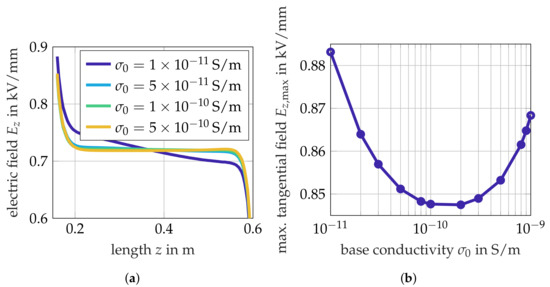
Figure 6.
Influence of the base conductivity : (a) Tangential electric field strength at the interface between XLPE and FGM; (b) Maximum tangential electric field strength at the interface.
Furthermore, Figure 7 shows the Joule losses and temperature stress inside of the FGM. It is observed that the Joule losses in the FGM layer rise linearly for S/m. Figure 7b shows the maximum and mean temperature in the FGM layer. The maximum temperature is constant for S/m; for larger values, the temperature rises quickly above the highest permissible temperature limit of 90 °C. The mean temperature in the FGM rises significantly with respect to the base conductivity for S/m. It is concluded that even a small variation in the base conductivity parameter leads to significantly increased power loss and significant temperature rise in the joint. Hence, an optimization of the base conductivity parameter involves a careful assessment of tangential field stress, Joule loss and operating temperatures. For the given cable joint model, an optimal trade-off between maximum tangential field stress, loss and temperature is reached by adopting a range of S/m for the base conductivity parameter.
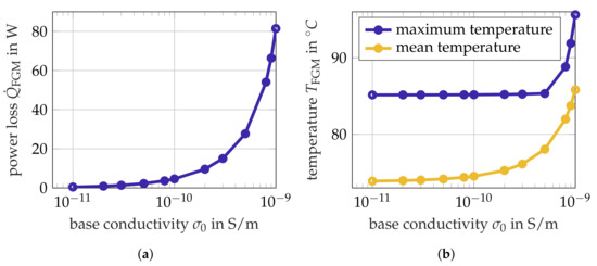
Figure 7.
Influence of the base conductivity : (a) Power loss ; (b) mean and maximum temperature inside the FGM.
4.2.2. Temperature Nonlinearity Exponent
The temperature dependence of DC insulation materials is a well known threat to HVDC cable systems, as it is the reason to the field inversion phenomenon [1]. Fundamental effects on the cable’s insulation have been discussed in [15,32]. For FGM materials as used in cable joints, literature data are available for field dependence only (cf. [31]). In the next step, it is investigated whether the temperature dependence is an important parameter for optimizing resistively graded cable joint designs with FGM layers. The temperature nonlinearity exponent governs the nonlinear temperature dependence in (1). The value , as proposed in [24], serves as a starting point for the investigation. Figure 8a shows that similarly to the previously analyzed base conductivity, there is a “threshold”-value for below which the field stress distribution gets imbalanced, i.e., . As Figure 8b shows, a minimum of the tangential peak field stress exists for .
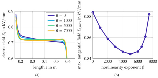
Figure 8.
Influence of the temperature nonlinearity exponent : (a) Tangential electric field strength along the interface between XLPE and FGM; (b) Maximum tangential electric field strength at the interface.
Furthermore, a choice of strongly increases the FGM loss and temperature stress (see Figure 9a). The temperature limit of the cable joint is surpassed for . For determining of the FGM, it is insufficient to require balance of the electric field stress at the interface. The example confirms that the Joule loss must be taken into account as well. The temperature dependence of the FGM layer is identified as an important and sensitive material design parameter for the overall joint behavior.
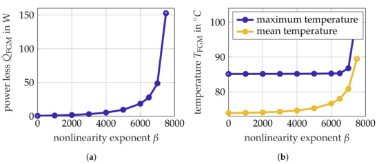
Figure 9.
Influence of the temperature nonlinearity exponent : (a) Power loss ; (b) mean and maximum temperature inside the FGM.
4.2.3. Switching Field Strength
The switching field strength, , determines the operating point at which the conductivity switches from the approximately linear to the nonlinear behavior. Furthermore, decreasing amplifies the slope of the conductivity curves. According to [23], the average tangential electric field along the evaluation path is defined with an additional safety margin of 10%. In our case, this corresponds to a switching field strength of kV/mm. Based on this, the switching field strength is swept in a range between 0.55 kV/mm to 0.9 kV/mm. The investigated variations of do not affect the overall tangential field stress distribution significantly (see Figure 10a) due to the moderate increase of the conductivity above the switching field strength. However, for kV/mm the maximal field strength increases almost linearly. The maximum is located close to the triple point. The switching field strength must, hence, be low enough to clip the field stress at this point.
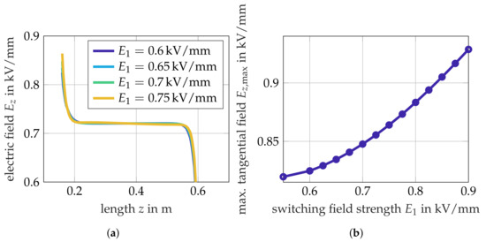
Figure 10.
Influence of the switching field strength : (a) Tangential electric field strength along the interface between XLPE and FGM; (b) Maximum tangential electric field strength at the interface.
For small switching field strengths, the FGM operates in the nonlinear range even in regular continuous operation. This is an unwanted effect, as it leads to increased losses (see Figure 11a). For kV/mm neither the mean nor the maximum temperature inside the FGM are significantly affected (see Figure 11b). Again, the decision for a switching field strength is a trade-off between the tangential field stress, the electric losses and the temperature. For the given cable joint model, a switching field strength of kV/mm as proposed by [23] performs very well.
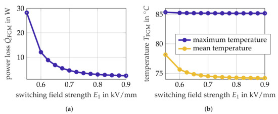
Figure 11.
Influence of the switching field strength : (a) Power loss ; (b) mean and maximum temperature inside the FGM.
5. Conclusions
The steady state behavior of a resistively graded high-voltage direct current cable joint with a nonlinear field grading material layer was investigated by electrothermally coupled finite element analysis. The proposed numerical procedure employs the damped successive substitution method, and proved a reliable approach to solve the coupled problem with high accuracy. The successful validation of the finite element analysis tool allowed for its application for investigating possible improvements of the field grading material performance. Therefore, the influence of the field grading material conductivity parameters on the field grading performance were investigated. The simulations demonstrated that the field grading material cannot be optimized by evaluating the tangential field grading performance at the interface only. The decision for the field grading material conductivity parameters is, rather, a trade-off between low losses in the field grading material and low field strengths at the interface. The investigated conductivity parameters are promising candidates for an optimization of the joint performance.
Author Contributions
Conceptualization, Y.S.-L., H.D.G. and M.K.; software, E.G., H.D.G. and Y.S.-L.; validation, G.R., and Y.S.-L.; formal analysis, G.R.; investigation, G.R. and Y.S.-L.; resources, H.D.G.; writing–original draft preparation, Y.S.-L., G.R.; writing–review and editing, E.G., H.D.G. and M.K.; visualization, G.R.; project administration, Y.S.-L. All authors have read and agreed to the published version of the manuscript.
Funding
This research received no external funding.
Acknowledgments
The authors thank Rashid Hussain for providing the simulation model and material characteristics published in [24].
Conflicts of Interest
The authors declare no conflict of interest.
References
- Cigré Working Group D1.56. Field grading in Electrical Insulation Systems; Number TB794; Conseil International des Grands Réseaux Électriques: Paris, France, 2020. [Google Scholar]
- Ghorbani, H.; Jeroense, M.; Olsson, C.O.; Saltzer, M. HVDC Cable Systems—Highlighting Extruded Technology. IEEE Trans. Power Deliv. 2014, 29, 414–421. [Google Scholar] [CrossRef]
- Chen, G.; Hao, M.; Xu, Z.; Vaughan, A.; Cao, J.; Wang, H. Review of high voltage direct current cables. CSEE J. Power Energy Syst. 2015, 1, 9–21. [Google Scholar] [CrossRef]
- 50hertz; Tennet. SuedOstLink: Erstmals Vergabe kunststoffisolierter Erdkabel für 525 Kilovolt Spannung. press release. 2020. [Google Scholar]
- Jörgens, C.; Clemens, M. A Review about the Modeling and Simulation of Electro-Quasistatic Fields in HVDC Cable Systems. Energies 2020, 13, 5189. [Google Scholar] [CrossRef]
- IEC 62067. Power Cables with Extruded Insulation and Their Accessories for Rated Voltages above 150 kV (Um = 170 kV) up to 500 kV (Um = 550 kV)—Test Methods and Requirements. International Standard, VDE Verlag: Berlin, Germany, 2011. Available online: https://webstore.iec.ch/preview/info_iec62067%7Bed2.0.RLV%7Den.pdf (accessed on 13 May 2021).
- IEC 60840. Power Cables with Extruded Insulation and Their Accessories for Rated Voltages above 30 kV (Um = 36 kV) up to 150 kV (Um = 170 kV)—Test Methods and Requirements. International Standard, VDE Verlag: Berlin, Germany, 2020. Available online: https://webstore.iec.ch/publication/63025 (accessed on 13 May 2021).
- IEC 62895. High Voltage Direct Current (HVDC) Power Transmission—Cables with Extruded Insulation and Their Accessories for Rated Voltages up to 320 kV for Land Applications—Test Methods and Requirements. International Standard, VDE Verlag: Berlin, Germany, 2017. Available online: https://webstore.iec.ch/publication/34020 (accessed on 13 May 2021).
- Cigré Working Group B1.32. Recommendations for Testing DC Extruded Cable Systems for Power Transmission at a Rated Voltage up to 500 kV; Number TB496; Conseil International des Grands réseaux Électriques: Paris, France, 2012. [Google Scholar]
- Gießel, M.; Hinrichsen, V.; Göhler, R.; Späck-Leigsnering, Y.; Gjonaj, E.; De Gersem, H. Electro-Thermal Simulations of High Voltage Metal-Oxide Surge Arresters with and without installed Grading Rings with regard to Thermal Stability. In Proceedings of the CIGRÉ Winnipeg 2017 Colloquium, Winnipeg, MB, Canada, 30 September 2017. [Google Scholar]
- Späck-Leigsnering, Y.; Gjonaj, E.; De Gersem, H. Electrothermal Optimization of Field Grading Systems of Station Class Surge Arresters. IEEE J. Multiscale Multiphy. Comput. Tech. 2019, 4, 29–36. [Google Scholar] [CrossRef]
- Clemens, M.; Gjonaj, E.; Pinder, P.; Weiland, T. Numerical simulation of coupled transient thermal and electromagnetic fields with the finite integration method. IEEE Trans. Magn. 2000, 36, 1448–1452. [Google Scholar] [CrossRef]
- Munteanu, I.; Timm, M.; Weiland, T. It’s About Time. IEEE Microw. Mag. 2010, 11, 60–69. [Google Scholar] [CrossRef]
- Späck-Leigsnering, Y.; Gjonaj, E.; De Gersem, H.; Weiland, T.; Gießel, M.; Hinrichsen, V. Electroquasistatic-thermal modeling and simulation of station class surge arresters. IEEE Trans. Magn. 2016, 52, 1–4. [Google Scholar] [CrossRef]
- Boggs, S.; Damon, D.; Hjerrild, J.; Holboll, J.; Henriksen, M. Effect of insulation properties on the field grading of solid dielectric DC cable. IEEE Trans. Power Deliv. 2001, 16, 456–461. [Google Scholar] [CrossRef]
- Qi, X.; Zheng, Z.; Boggs, S. Engineering with nonlinear dielectrics. IEEE Electr. Insul. Mag. 2004, 20, 27–34. [Google Scholar] [CrossRef]
- Bodega, R. Space Charge Accumulation in Polymeric High Voltage DC Cable Systems. Ph.D. Thesis, Delft University of Technology, Delft, The Netherlands, 2006. [Google Scholar]
- Jörgens, C.; Clemens, M. Conductivity-based model for the simulation of homocharges and heterocharges in XLPE high-voltage direct current cable insulation. IET Sci. Meas. Technol. 2019, 13, 975–983. [Google Scholar] [CrossRef]
- Jörgens, C.; Kasolis, F.; Clemens, M. Numerical Simulations of Temperature Stability Limits in High-Voltage Direct Current Cable Insulations. IEEE Trans. Magn. 2019, 55, 1–4. [Google Scholar] [CrossRef]
- Frobin, S.J.; Freye, C.; Niedik, C.F.; Jenau, F.; Haering, D.; Schroeder, G. Thermal Modelling of HVDC Cables under Consideration of Measured Temperature Profiles. In Proceedings of the VDE ETG—Fachtagung Hochspannungstechnik 2018, Berlin, Germany, 12–14 November 2018. [Google Scholar]
- Saltzer, M.; Christen, T.; Sörqvist, T.; Jeroense, M. Electro-thermal simulations of HVDC cable joints. In Proceedings of the ETG Workshop Feldsteuernde Isoliersysteme, Darmstadt, Germany, 22–23 November 2011. [Google Scholar]
- Frobin, S.J.; Niedik, C.F.; Freye, C.; Jenau, F.; Haring, D.; Schroder, G. A Generic Approach for HVDC Cable Accessories Modelling. In Proceedings of the 2018 IEEE 2nd International Conference on Dielectrics (ICD), Budapest, Hungary, 1–5 July 2018. [Google Scholar] [CrossRef]
- Secklehner, M.; Hussain, R.; Hinrichsen, V. Tailoring of new field grading materials for HVDC systems. In Proceedings of the 2017 INSUCON—13th International Electrical Insulation Conference (INSUCON), Birmingham, UK, 16–18 May 2017. [Google Scholar] [CrossRef]
- Hussain, R.; Hinrichsen, V. Simulation of thermal behavior of a 320 kV HVDC cable joint with nonlinear resistive field grading under impulse voltage stress. In Proceedings of the CIGRÉ Winnipeg 2017 Colloquium, Winnipeg, MB, Canada, 30 September 2017. [Google Scholar]
- Jörgens, C.; Clemens, M. Comparison of Two Electro-Quasistatic Field Formulations for the Computation of Electric Field and Space Charges in HVDC Cable Systems. In Proceedings of the 2019 22nd International Conference on the Computation of Electromagnetic Fields (COMPUMAG), Paris, France, 15–19 July 2019. [Google Scholar] [CrossRef]
- Mazzanti, G.; Marzinotto, M. Extruded Cables for High-Voltage Direct-Current Transmission: Advances in Research and Development; Wiley: Hoboken, NJ, USA, 2013. [Google Scholar]
- Küchler, A. High Voltage Engineering: Fundamentals–Technology–Applications, 1st ed.VDI-Buch: Berlin, Germany, 2018. [Google Scholar]
- Farahani, M.; Werle, P.; Hohloch, J.; Hutt, W. Untersuchungen zur Durchschlagfestigkeit von Polyethylen-Silikon-Grenzflächen. In Proceedings of the VDE ETG—Fachtagung Hochspannungstechnik 2018, Berlin, Germany, 12–14 November 2018. [Google Scholar]
- Kaumanns, J. HVDC Cable Systems—State of the Art Technologies and Future Trends. In Proceedings of the International High Voltage Direct Current 2015 Conference, Seoul, Korea, 18–22 October 2015. [Google Scholar]
- Cigré Working Group B1.22. Cable Accessory Workmanship on Extruded High Voltage Cables; Number TB476; Conseil International des Grands Réseaux Électriques: Paris, France, 2011. [Google Scholar]
- Pradhan, M.; Greijer, H.; Eriksson, G.; Unge, M. Functional behaviors of electric field grading composite materials. IEEE Trans. Dielectr. Electr. Insul. 2016, 23, 768–778. [Google Scholar] [CrossRef]
- Qin, S.; Boggs, S. Design considerations for high voltage DC components. IEEE Electr. Insul. Mag. 2012, 28, 36–44. [Google Scholar] [CrossRef]


Publisher’s Note: MDPI stays neutral with regard to jurisdictional claims in published maps and institutional affiliations. |
© 2021 by the authors. Licensee MDPI, Basel, Switzerland. This article is an open access article distributed under the terms and conditions of the Creative Commons Attribution (CC BY) license (https://creativecommons.org/licenses/by/4.0/).