Communication

Design Study on Customised Piezoelectric Elements for Energy Harvesting in Total Hip Replacements

Department of Orthopaedics, Rostock University Medical Center, 18057 Rostock, Germany
*
Author to whom correspondence should be addressed.
Energies 2021, 14(12), 3480; https://doi.org/10.3390/en14123480
Submission received: 5 May 2021 / Revised: 3 June 2021 / Accepted: 8 June 2021 / Published: 11 June 2021

Abstract

:
Energy harvesting is a promising approach to power novel instrumented implants that have passive sensory functions or actuators for therapeutic measures. We recently proposed a new piezoelectric concept for energy harvesting in total hip replacements. The mechanical implant safety and the feasibility of power generation were numerically demonstrated. However, the power output for the chosen piezoelectric element was low. Therefore, we investigated in the present study different geometry variants for an increased power output for in vivo applications. Using the same finite element model, we focused on new, customised piezoelectric element geometries to optimally exploit the available space for integration of the energy harvesting system, while maintaining the mechanical safety of the implant. The result of our iterative design study was an increased power output from 29.8 to 729.9 µW. This amount is sufficient for low-power electronics.

1. Introduction

Instrumentation of implants is a promising approach to enhance their functionalities and further improve the clinical outcome. With regard to joint endoprostheses, sensors for monitoring implant-related parameters (e.g., implant loading and daily life activity, implant loosening, etc. [1]) can provide data for clinical decisions and therapeutic actions. These data are also relevant for ongoing implant development. Beyond passive diagnostic functions, active measures are investigated, e.g., electrical stimulation to promote bone growth [2,3,4]. To power sensors and actuators, an adequate energy supply is required. Therefore, energy harvesting is an innovative solution that provides continuous and independent energy for an autonomous instrumented implant without the drawbacks of batteries (limited lifetime, risk of leakage) or external power supply (dependence on external components).
The first concept for an energy harvesting system (EHS) for a load bearing endoprosthetic implant was reported by Platt et al. [5,6]. Piezoelectric multilayer elements were placed in the tibial tray of a total knee replacement (TKR). This system was improved by Almouahed et al. [7,8]. Wilson et al. and Safaei et al. modified the concept by moving the piezoelectric transducers to the polyethylene insert of the TKR [9,10]. Other EHS concepts in TKR were based on electromagnetic or triboelectric transducers [11,12]. With regard to total hip replacements (THR), Morais et al. were the first presenting an EHS [13]. The electromagnetic generator, consisting of coils and a magnet-spring system, was placed in a total hip stem. This concept was extended by Santos et al. to a multisource EHS with an additional rotation movement-based electromagnetic generator in the femoral joint and a vibration-based piezoelectric generator in the implanted femoral head [14]. Since then and to the best of the author’s knowledge, our recently published study is the first work on EHSs in THRs [15]. We presented a piezoelectric-based concept that transduces the mechanical loads from human gait into electrical energy by transmitting the acting force on the THR to a lead zirconate titanate (PZT) multilayer element deforming the element and applying mechanical strain (see Figure 1). The piezoelectric element is encapsulated in an ultra-high molecular weight polyethylene (UHMW-PE) housing which fills a cavity excised from the original metallic total hip stem (see Figure 2, Materials and Methods). The generated energy can be used to power various instrumentations. By linking the generated voltage to the implant loading, the EHS can serve in a first application as a self-powered load sensor.
In our previous work [15], we numerically investigated the implant’s fatigue safety and the feasibility of energy harvesting, however, the numerically approximated power output was quite low for the assumed off-the-shelf piezoelectric element (single configuration 8.1 µW, stacked configuration 31.1 µW). Hence, the aim of the present numerical design study was to investigate changes of the cavity and piezoelectric element to increase the maximum power output, while maintaining the mechanical safety of the implant using finite element analysis (FEA). Therefore, the geometry of the introduced cavity was modified or the geometry of the piezoelectric element was changed to better exploit the space available. For the latter, customised geometries were analysed. To the author’s knowledge this approach is new in piezoelectric energy harvesting for load-bearing orthopaedic implants; in the work of the above-referenced groups on EHS concepts in TKR only standard products have been employed to adopt the geometry (seize, height) or number of piezoelectric elements [8,10].

2. Materials and Methods

The finite element model was based on our previous work and is briefly described below, further details are specified in [15]. Following that, the different regarded geometry variants and the process of our iterative design study for the customised geometries were described.

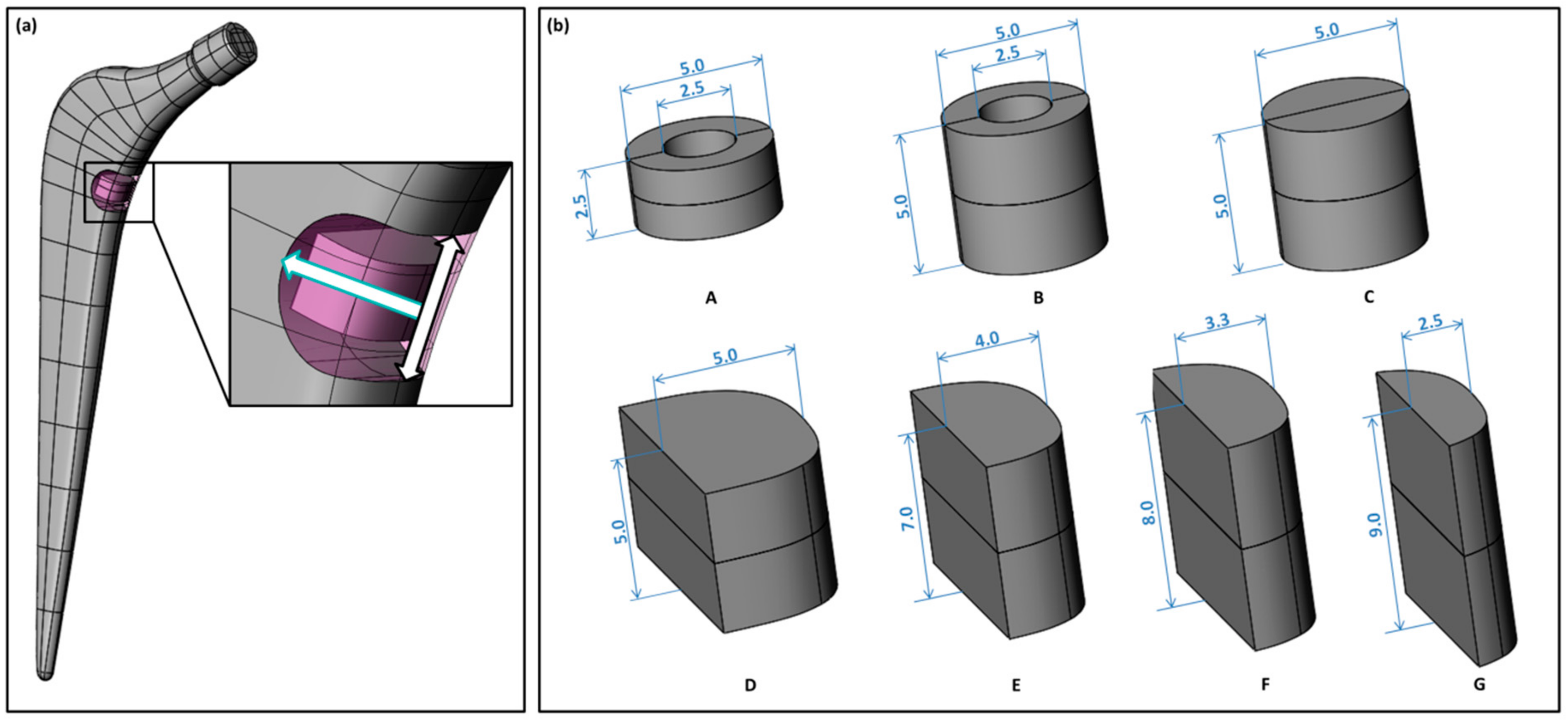
2.1. Finite Element Model
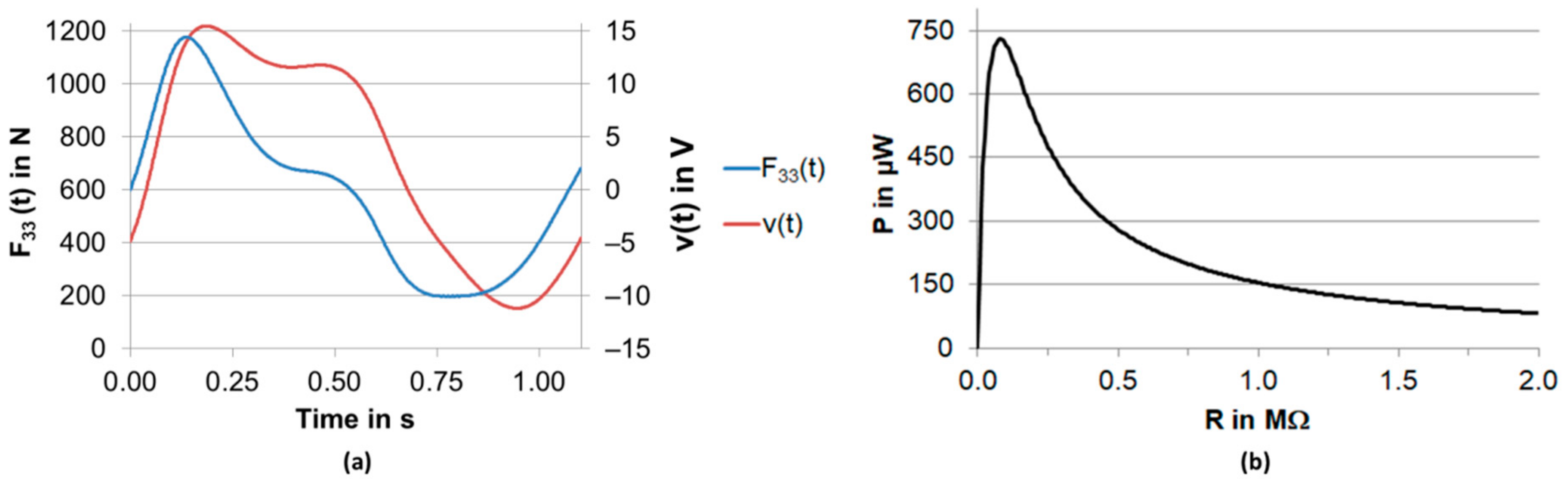
A femoral geometry from a previous reconstruction on basis of computed tomography (CT) data was used [16,17]. Landmarks, necessary for the virtual implantation and load application were created (e.g., femur axis, neck axis, femoral head centre, epicondyles, femoral notch). A femur coordinate system was defined according to Bergmann et al. [18]. The total hip stem geometry (Exeter V40, size 37.5 mm N°3, Stryker, Howmedica Osteonics Corp, Mahwah, NJ, USA) was generated and reconstructed by 3D-scan. Accordingly, landmarks were created (implant stem axis, implant neck axis and virtual head centre) in SolidWorks 2018 (Dassault Systèmes, VélizyVillacoublay, France). From the implant, a cavity was subtracted and replaced with a UHMW-PE housing to contain the various piezoelectric element geometries. The initial designs of the cavity and piezoelectric element were according to [15]. Then, the implant’s virtual head centre and the femoral head centre were superimposed and the total hip stem axis was aligned with the femoral axis. Around the implant, a bone cement mantle of 3 mm thickness was defined. To complete the virtual implantation, the femoral neck and femoral head were resected and a bone cavity was created to house the implant and the bone cement mantle. Figure 1 shows the virtual implantation and the different components of the modified implant.
The full CAD model was imported into the finite element software ANSYS Workbench V19.2 (Ansys Inc., Canonsburg, PA, USA). According to Heller et al. (based on in vivo measurements [18] and musculo-skeletal modelling [19]), a reduced set of four muscle forces and a hip contact force for normal walking were applied for the instance of maximum total hip contact force, scaled to the body weight of an average patient of 75 kg [20]. Using the physiologically based boundary conditions of Speirs et al. [21], the system was fully constrained allowing the typical bending of a femur [15].
Between the bone and the bone cement mantle, a bonded contact was applied. All other contacts were defined to be frictional (frictional coefficient µ = 0.35 between bone cement mantel and implant [22], µ = 0.15 between UHMW-PE housing and implant [23]; for contact between the UHMW-PE housing and piezoelectric element, respectively, bone cement mantle µ = 0.3 was assumed).
The complex geometries of femur, implant and UHWM-PE housing were meshed with quadratic solid tetrahedral elements while the simpler geometries of the piezoelectric element and the bone cement layer were meshed with quadratic hexahedral elements. The mesh densities for the different components were in accordance with the mesh densities from our sensitivity analysis from [15], based on a mesh independence study. Please note that the single layers of the multilayer piezoelectric element are not individually modelled in contrast to our previous work [15], meaning in this region the element height is reduced. For the larger customised geometries, the very small mesh size would substantially increase the numerical problem size and exceed the computing capacity of our hardware system as pretests showed. Since the simulated open circuit voltage was of no interest in this study, this approach is straightforward. However, we compared both approaches for the off-the-shelf configurations (see below).
All materials were defined linear elastic. The material properties are listed in Table 1. We accounted for the heterogeneous stiffness distribution of the bone by applying material mapping. Bonemat V3.2 was used to assign different Young’s moduli on basis of the CT data [24]. The density–elasticity relationship of Morgen et al. on basis of the apparent density ρapp [25] was assumed with a maximum Young’s modulus of 20 GPa, please see [15] for more detail.
The implicit static structural simulations were performed on a high-performance Linux cluster with two Intel® Xeon® Gold 6248 CPU processors (2.50 GHz) and 192 GB RAM per node. A sparse direct solver was used.

2.2. Postprocessing

With regard to the mechanical implant safety, we evaluated the von Mises stress in the metallic implant component at the cavity ground (σImp), where a local stress concentration is induced by integration of the EHS. This parameter was considered uncritical when not exceeding 290.9 MPa which was the global stress maximum for the unmodified geometry in the same loading situation, shown in [15]. For the piezoelectric element, the von Mises stress (σPiez) was evaluated in the mid plane, since the contact situation leads to local stress singularities at the top and bottom end faces. The limit was defined as 30.0 MPa. This value was specified by the manufacturer as maximum preload for using the element with a constant force [32].
For the approximation of the generated power, we followed the approach of Wilson and Safaei et al., and calculated the generated voltage v(t) on basis of a force profile F33(t) by solving the differential equation for different load resistance R
n layer ε 33 T A h n layer dv ( t ) dt + v t R = n layer d 33 F ˙ 33 ( t ) ,
where the first term represents the capacity of the piezoelectric element [9,10]. The piezoelectric element is defined by its base area A, its height h, the number of layers nlayer and the piezoelectric constants ε 33 T and d33. In the design study, the base area A of the element was variable, as well as the height h and the resulting number of layers nlayer. The layer thickness was kept constant at hlayer = 0.05 mm as for the off-the-shelf piezoelectric elements specified by the manufacturer. The used input parameters for the piezoelectric element are listed in Table 2. Since the off-the-shelf piezoelectric elements had passive top and bottom layers of around 0.175 mm thickness at a height of 2.5 mm for each single element (i.e., 2.15 mm of active height and 43 layers for a single element and 4.35 mm of active height and 86 layers for the stacked element, respectively) we assumed an according passive proportion for the customised geometries. If necessary, we reduced the active height to obtain an integer number of layers, thereby choosing for a conservative power approximation.
The acting hip contact force for a full gait cycle of the duration T for normal walking of a patient with average weight from Bergmann et al. was scaled to the contact force acting on the piezoelectric elements end faces F33 from the FEA [18]. The resulting load profile F33(t) approximated the force profile on the piezoelectric element, requiring only the simulation of a single load step (Figure 3a exemplary shows the scaled force profile for the final design). The generated power for different load resistance R was calculated by
P = 1 T 0 T v 2 t R dt
The maximum power for the best matching resistance was used as output parameter. All output parameters are summarised in Table 3.

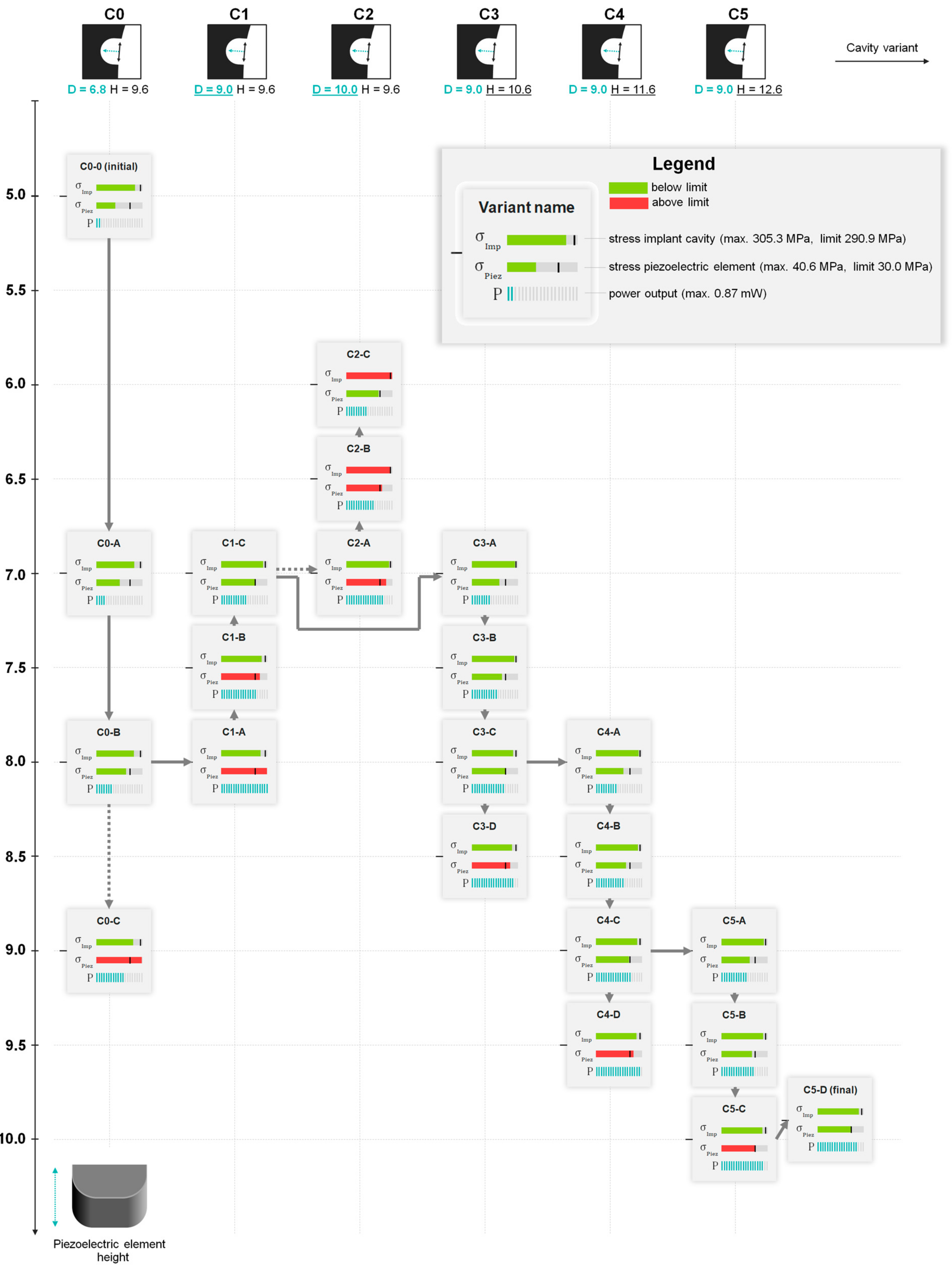
2.3. Geometry Variants

Recalculation of previous data: For the customised geometries the individual representation of the multilayer elements would exceed the computational capacity, as mentioned above. For comparison with our previous data and as reference basis for new simulations, we recalculated the off-the-shelf configurations (single and stacked multilayer piezoelectric element, see Figure 2) with the approach described above, neglecting the layers in the simulation, and considering them only for the power calculation.
New geometries: In addition to the off-the-shelf stacked piezoelectric element with a ring base area, we considered a full cylinder stacked multilayer element.
To better use the available space in the cavity, a fully customised piezoelectric element cross-section was generated (see Figure 2). It was ensured that the piezoelectric element is fully encapsulated by the UHMW-PE housing and a minimum wall thickness comparable to the off-the-shelf configurations was maintained. The initial height was chosen to be comparable to the stacked multilayer element (h = 5 mm). The general configuration (material properties, layer thickness, proportion of passive layers to the active height assuming stacks) was unchanged.
Iterative design study: On basis of the initial customised geometry, we conducted a design study to optimise the power output. Starting with the initial cavity design, we successively changed the piezoelectric element’s height to find the geometry providing the maximum power output, but ensuring compliance with the defined critical stress values (Table 3). The larger the piezoelectric element’s height, the shorter its extension towards the cavity needed to be defined to fit in the UHMW-PE housing (see Figure 2b, A to G). The best design point was then used as input for a new cavity geometry where we changed the cavity height or depth (see Figure 2a for the definition). Again, the piezoelectric element’s height was changed to comply with our specified stress values. After five new cavity geometries and over 20 simulated design points, we stopped the study. All design point geometries are presented and listed in Figure A1 and Table A1, Appendix A.

3. Results

Initially, our simplified approach neglecting the single layers was analysed on the basis of the off-the-shelf configurations. The results were compared to identical configurations from previous data from [15]. The difference was < 5% for all output parameters but for the stress in the stacked piezoelectric element (see in Table 4). However, the absolute difference of < 2 MPa was acceptably small. All results are summarised in Table 4.
The generated power for the off-the-shelf geometries was highest for the stacked configuration (29.8 µW, factor 3.7 compared to the single element), see Table 5. The acting contact force F33 was notably larger, and the stress in the piezoelectric element rose compared to the single element. The full cylinder also absorbed more load, however, the stress in the piezoelectric element was smaller and thereby less voltage and power were generated. All the three design variants fulfilled the stress criteria for the metallic implant component and for the piezoelectric element (see Table 5).
The initial customised geometry was of the same height as the stacked circular geometries and showed a 2.6 times higher power output (77.8 µW). By our iterative design study, we could successively find new geometries fulfilling our specified stress limits and presenting higher power output (see Figure A1 and Table A1, Appendix A). We stopped the study after over 20 design points and 5 new cavity geometries. The calculated power for the final design was 729.9 µW (i.e., an increase of nearly factor 25 to the stacked off-the-shelf configuration, see Table 5).
For the final design, the force profile F33(t) is shown in Figure 3a together with the generated voltage profile for the best matching load resistor (R = 0.08 MΩ). The power output for different load resistance is displayed in Figure 3b, with the calculated peak of 729.9 µW.

4. Discussion

The results for the simplified modelling of the piezoelectric element showed that the influence was minimal when individual layers of the piezoelectric element were neglected. This was expected, since apart from that the model and approach were identical. The impact on the metallic component itself can be disregarded. The deviations for the generated power were higher than for the contact force F33. This has already been shown in our previous work and can be explained by the linear relationship between force and generated voltage which in contrast is contained as squared value in the calculation of the power (see Equation (2)) [15]. The difference for the stress in the piezoelectric element especially for the larger stacked configuration may result from the different height of the finite elements in the very area. The element height was notably smaller when the individual layers were modelled. With respect to the minor absolute deviation, the difference is acceptable and the approach still considered straightforward since the reduction of the model size is necessary to allow the simulation of larger piezoelectric elements of increased height or increased base area. To minimise the mesh density influence for a good comparability of the different design points in the iterative design study, the finite element height for the piezoelectric elements was kept constant for all design points.
As our previous study already showed, a stacked configuration with the same base area led to a higher force transmission, resulting in a higher stress and higher generated power [15]. In contrast, a full cylinder of the same height had no benefit with regard to the power. The slight increased force value did not compensate the increased stiffness by the larger base area, leading to lower deformation and stresses, and thereby lower power output. However, a higher force F33 can be withstood. This can be realised by increasing the height or base area to maximise the force transmission on the piezoelectric element. Therefore, the overall design aspect of the EHS with the mediating function of the UHWM-PE housing allows perfectly matching the piezoelectric elements geometry while maintaining the cavity geometry. This is demonstrated by the initial customised geometry; increasing the base area using the maximum available space for the same height largely raised the generated power but showed a tolerable stress level. The potential of a higher piezoelectric element, pushing the stress to the specified allowed limit, is not even exploited.
The iterative geometry study was a successful approach and highlighted the following aspect: by changing the piezoelectric element’s height, a design point for each generation was found which was below the defined stress levels but had a higher generated power output than the best design from the previous cavity geometry generation. Only for one cavity geometry no valid design point was found. The final power output value of nearly 730 µW shows improvement to the off-the-shelf designs, and improvement by the iterative geometry study, when comparing the final design to the best design of the initial cavity geometry. The voltage and power curves, exemplarily shown for the final design, are in accordance with our previous work [15]. Due to the higher acting force level of F33 and the new configuration of the piezoelectric element, the generated voltage maximum was higher and the best matching resistance was slightly shifted to a lower value.
The calculated generated power is in the range of generated power by EHSs of other work groups: Almouahed et al. increased their output for the optimised design from 1.81 to 3.28 mW [8], Safaei et al. presented a power output of 269.1 µW for their latest design [33] (also raised by a factor > 20 compared to their initial work [34,35]). With regard to EHSs in THRs, Santos et al. calculated a power output of around 55 µW which summed up for all three harvesters [14]. Studies have shown that low power sensory and active functions in implants (e.g., intermitting monitoring and data transmission) need power sources in the range of 100 µW [11,36]. Therefore, the generated power output of our proposed EHS with a customised design can be considered sufficient. We do not expect that further increase by a higher number of additional piezoelectric elements is feasible. In contrast to TKR where much more space is available (in the polyethylene insert or the tibial tray), the area for piezoelectric element placement is much more limited in THR, where the piezoelectric element must be placed in an area which is under compressive load and where the implant cross section is large enough [15]. With our design we have found a good trade-off for a cavity size, which is sufficiently large to integrate a piezoelectric element, but does maintain the mechanical safety of the implant.
A limitation of our study is the calculation of the generated power only for resistive loads. Typical energy harvesting circuitry includes further and more complex components, e.g., rectifiers to convert the alternating current to direct current, voltage regulators and storage devices [37,38]. The efficiency of this electronic circuit determines the amount of energy that is available from the raw harvested energy. For low-frequency piezoelectric transducers, minimum energy loss is a challenging task and circuitry design was discussed already for the first energy harvesting concepts in orthopaedic implants [6,39]. This topic is part of ongoing research, even though commercialised solutions are already available [37,38,40]. In future studies, we will use the piezoelectric EHS as part of a self-powered load sensor. Within this work, we are able to investigate energy harvesting circuitry and efficiency.
With regard to the chosen limits for the evaluation of the mechanical safety, one has to keep in mind that fatigue values are usually determined for test specimens under specific manufacturing and testing conditions. The chosen value for the metallic component was the maximum stress value, taken from a study with the identical loading situation for the unmodified implant geometry [15]. This approach is conservative, since the literature value for the same material, investigated under a stress ratio typical for implants (R = 0.1) at 37 °C tested in Eagle’s medium, is notably higher (470 MPa) [41]. This means that the latter value could also be suited for comparison, allowing higher stress values for the metallic component than in this study; however, the heat treatment or surface finish could differ from the present sample. In our recent research, we showed for our initial design that higher fatigue stress values can be endured [42]. In the absence of fatigue data for multilayer piezoelectric elements used as transducers under the specified loading conditions, we used the manufacturer’s specification for maximum preload as the critical value for the piezoelectric element. Other literature fatigue data of stacked multilayer piezoelectric element actuators with a preload of 20 MPa is available [43]. A different manufacturer with comparable multilayer elements recommends a compressive stress range of up to 80 MPa for unstacked elements [44]. More specific fatigue data, especially for stacked multilayer piezoelectric elements in comparable loading situations and tested as transducer is desirable to exploit the full power generation capacity. The latter highlights the necessity of experimental testing.
In conclusion, this numerical study showed the potential of piezoelectric energy harvesting in THRs with customised geometries. The effort for the new geometries can be outweighed by the highly increased power output in contrast to only relying on standard products. Since manufacturing of customised piezoelectric geometries is many times more expansive than off-the-shelf elements, our work provides the required basis to proceed to experimental investigations. After realising the production of the proposed piezoelectric elements, experimental testing of the power generation and of the fatigue properties of the full system is required. This should also include worst case scenarios, e.g., representing higher loads simulating running, stumbling or implant loosening according to [42]. If the experiments show data allowing for higher loadings, the presented design study could be redone with new limit values. With regard to biocompatibility of the system and the toxicity of lead in PZT ceramics, the UHMW-PE housing already serves as environmental sealing which can be improved by other encapsulation techniques [15], however future studies should also consider lead-free piezoelectric materials [38].

Author Contributions

Conceptualisation, D.K. and H.-E.L.; methodology, H.-E.L. and D.K.; software, H.-E.L.; investigation, H.-E.L.; resources, R.B. and D.K.; data curation, H.-E.L.; writing—original draft preparation, H.-E.L.; writing—review and editing, D.K. and R.B.; visualisation, H.-E.L.; supervision, D.K. and R.B.; project administration, D.K. and R.B.; funding acquisition, D.K. and R.B. All authors have read and agreed to the published version of the manuscript.

Funding

This research is funded by the Deutsche Forschungsgemeinschaft (DFG, German Research Foundation)—SFB 1270/1—299150580.

Acknowledgments

We thank Philipp Spaans for the concise graphical representation of the design study (block diagram Figure A1 in Appendix A).

Conflicts of Interest

The authors declare no conflict of interest.

Appendix A

Figure A1. Variants of the geometry study for the customised geometries showing the different cavity designs from left to right (the changed cavity parameters are underlined), all design points are ordered according to the height of the piezoelectric elements (top down). The arrows indicate the proceeded progress. The evaluated stresses (MPa) and power (mW) are shown in bars based on the maximum reached values. Green bars indicate a value below the critical value, and red above. For quantitative date, see Table A1.
Energies 14 03480 g0a1
Table A1. Overview of all designs with customised piezoelectric element geometries.
Energies 14 03480 i007

References

  1. Ledet, E.H.; Liddle, B.; Kradinova, K.; Harper, S. Smart implants in orthopedic surgery, improving patient outcomes: A review. Innov. Entrep. Health 2018, 5, 41–51. [Google Scholar] [CrossRef] [Green Version]
  2. Schmidt, C.; Zimmermann, U.; Van Rienen, U. Modeling of an Optimized Electrostimulative Hip Revision System under Consideration of Uncertainty in the Conductivity of Bone Tissue. IEEE J. Biomed. Health Inform. 2015, 19, 1321–1330. [Google Scholar] [CrossRef]
  3. Raben, H.; Kämmerer, P.W.; Bader, R.; Van Rienen, U. Establishment of a Numerical Model to Design an Electro-Stimulating System for a Porcine Mandibular Critical Size Defect. Appl. Sci. 2019, 9, 2160. [Google Scholar] [CrossRef] [Green Version]
  4. Dos Santos, M.P.S.; Marote, A.; Santos, T.; Torrão, J.; Ramos, A.; Simões, J.A.O.; da Cruz e Silva, O.A.B.; Furlani, E.P.; Vieira, S.I.; Ferreira, J.A.F. New cosurface capacitive stimulators for the development of active osseointegrative implantable devices. Sci. Rep. 2016, 6, 30231. [Google Scholar] [CrossRef]
  5. Platt, S.R.; Farritor, S.; Garvin, K.; Haider, H. The Use of Piezoelectric Ceramics for Electric Power Generation within Orthopedic Implants. IEEE/ASME Trans. Mechatron. 2005, 10, 455–461. [Google Scholar] [CrossRef]
  6. Platt, S.R.; Farritor, S.; Haider, H. On Low-Frequency Electric Power Generation with PZT Ceramics. IEEE/ASME Trans. Mechatron. 2005, 10, 240–252. [Google Scholar] [CrossRef]
  7. Almouahed, S.; Gouriou, M.; Hamitouche, C.; Stindel, E.; Roux, C. Self-powered instrumented knee implant for early detection of postoperative complications. In Proceedings of the 2010 Annual International Conference of the IEEE Engineering in Medicine and Biology, Buenos Aires, Argentina, 31 August–4 September 2010; pp. 5121–5124. [Google Scholar] [CrossRef]
  8. Almouahed, S.; Hamitouche, C.; Stindel, E. Optimized Prototype of Instrumented Knee Implant: Experimental Validation. IRBM 2017, 38, 250–255. [Google Scholar] [CrossRef]
  9. Wilson, B.E. Modeling and Experimentation for Evaluation of Piezoelectric Sensors for In-Vivo Monitoring. Master’s Thesis, Tennessee Technological University, Cookeville, TN, USA, 2015. [Google Scholar]
  10. Safaei, M. A Piezoelectric Instrumented Total Knee Replacement for Sensing and Energy Harvesting. Ph.D. Thesis, Tennessee Technological University, Cookeville, TN, USA, 2019. [Google Scholar]
  11. Luciano, V.; Sardini, E.; Serpelloni, M.; Baronio, G. An energy harvesting converter to power sensorized total human knee prosthesis. Meas. Sci. Technol. 2014, 25, 25702. [Google Scholar] [CrossRef] [Green Version]
  12. Ibrahim, A.; Jain, M.; Salman, E.; Willing, R.; Towfighian, S. A smart knee implant using triboelectric energy harvesters. Smart Mater. Struct. 2019, 28, 025040. [Google Scholar] [CrossRef]
  13. Morais, R.; Silva, N.; Santos, P.; Frias, C.; Ferreira, J.; Ramos, A.; Simõesd, J.; Baptista, J.; Reis, M. Permanent magnet vibration power generator as an embedded mechanism for smart hip prosthesis. Procedia Eng. 2010, 5, 766–769. [Google Scholar] [CrossRef]
  14. Santos, M.; Ferreira, J.; Ramos, A.; Pascoal, R.; Morais, R.; Silva, N.; Simoes, J.; Reis, M.J.C.S.; Boeri, C.N.; Festas, A.; et al. Multi-Source Energy Harvesting Power Generators for Instrumented Implants—Towards the Development of a Smart Hip Prosthesis. In Biodevices 2012, Proceedings of the International Conference on Biomedical Electronics and Devices, Vilamoura, Algarve, Portugal, 1–4 February 2012; [integrated in BIOSTEC (International Joint Conference on Biomedical Engineering Systems and Technologies)]. International Conference on Biomedical Electronics and Devices; Gabriel, J., Ed.; SciTePress: Setubal, Portugal, 2012; pp. 71–81. ISBN 978-989-8425-91-1. [Google Scholar]
  15. Lange, H.-E.; Hohlfeld, D.; Bader, R.; Kluess, D. A piezoelectric energy harvesting concept for an energy-autonomous instrumented total hip replacement. Smart Mater. Struct. 2020, 29, 115051. [Google Scholar] [CrossRef]
  16. Soodmand, E.; Kluess, D.; Varady, P.A.; Cichon, R.; Schwarze, M.; Gehweiler, D.; Niemeyer, F.; Pahr, D.; Woiczinski, M. Interlaboratory comparison of femur surface reconstruction from CT data compared to reference optical 3D scan. Biomed. Eng. Online 2018, 17, 29. [Google Scholar] [CrossRef] [Green Version]
  17. Kluess, D.; Soodmand, E.; Lorenz, A.; Pahr, D.; Schwarze, M.; Cichon, R.; Varady, P.A.; Herrmann, S.; Buchmeier, B.; Schröder, C.; et al. A round-robin finite element analysis of human femur mechanics between seven participating laboratories with experimental validation. Comput. Methods Biomech. Biomed. Eng. 2019, 22, 1020–1031. [Google Scholar] [CrossRef] [PubMed]
  18. Bergmann, G.; Deuretzbacher, G.; Heller, M.; Graichen, F.; Rohlmann, A.; Strauss, J.; Duda, G. Hip contact forces and gait patterns from routine activities. J. Biomech. 2001, 34, 859–871. [Google Scholar] [CrossRef]
  19. Heller, M.; Bergmann, G.; Deuretzbacher, G.; Dürselen, L.; Pohl, M.; Claes, L.; Haas, N.; Duda, G. Musculo-skeletal loading conditions at the hip during walking and stair climbing. J. Biomech. 2001, 34, 883–893. [Google Scholar] [CrossRef]
  20. Heller, M.; Bergmann, G.; Kassi, J.-P.; Claes, L.; Haas, N.; Duda, G. Determination of muscle loading at the hip joint for use in pre-clinical testing. J. Biomech. 2005, 38, 1155–1163. [Google Scholar] [CrossRef]
  21. Speirs, A.; Heller, M.; Duda, G.N.; Taylor, W.R. Physiologically based boundary conditions in finite element modelling. J. Biomech. 2007, 40, 2318–2323. [Google Scholar] [CrossRef]
  22. Nuño, N.; Groppetti, R.; Senin, N. Static coefficient of friction between stainless steel and PMMA used in cemented hip and knee implants. Clin. Biomech. 2006, 21, 956–962. [Google Scholar] [CrossRef]
  23. Wang, Y.; Yin, Z.; Li, H.; Gao, G.; Zhang, X. Friction and wear characteristics of ultrahigh molecular weight polyethylene (UHMWPE) composites containing glass fibers and carbon fibers under dry and water-lubricated conditions. Wear 2017, 380–381, 42–51. [Google Scholar] [CrossRef]
  24. Taddei, F.; Schileo, E.; Helgason, B.; Cristofolini, L.; Viceconti, M. The material mapping strategy influences the accuracy of CT-based finite element models of bones: An evaluation against experimental measurements. Med. Eng. Phys. 2007, 29, 973–979. [Google Scholar] [CrossRef]
  25. Morgan, E.F.; Bayraktar, H.H.; Keaveny, T.M. Trabecular bone modulus–density relationships depend on anatomic site. J. Biomech. 2003, 36, 897–904. [Google Scholar] [CrossRef]
  26. Kempf, I.; Leung, K.S.; Grosse, A.; Haarman, H.J.T.M.; Seidel, H.; Taglang, G. Practice of Intramedullary Locked Nails: Scientific Basis and Standard Techniques Recommended by AIOD; Springer: Berlin/Heidelberg, Germany, 2002; ISBN 3642563309. [Google Scholar]
  27. Saha, S.; Pal, S. Mechanical properties of bone cement: A review. J. Biomed. Mater. Res. 1984, 18, 435–462. [Google Scholar] [CrossRef]
  28. Kurtz, S.M. UHMWPE biomaterials handbook. In Ultra High Molecular Weight Polyethylene in Total Joint Replacement and Medical Devices, 2nd ed.; Academic: London, UK, 2009; ISBN 9780123747211. [Google Scholar]
  29. PI Ceramic GmbH. Material Coefficients PIC255: V4.3; PI Ceramic GmbH: Lederhose, Germany, 2017. [Google Scholar]
  30. Zysset, P.K.; Guo, X.E.; Hoffler, C.E.; Moore, K.E.; Goldstein, S.A. Elastic modulus and hardness of cortical and trabecular bone lamellae measured by nanoindentation in the human femur. J. Biomech. 1999, 32, 1005–1012. [Google Scholar] [CrossRef]
  31. Ashman, R.; Cowin, S.; Van Buskirk, W.; Rice, J. A continuous wave technique for the measurement of the elastic properties of cortical bone. J. Biomech. 1984, 17, 349–361. [Google Scholar] [CrossRef]
  32. PI Ceramic GmbH. Data Sheet Round PICMA® Chip Actuators: Miniature Multilayer Piezo Actuators with and without Inner Hole. Available online: https://static.piceramic.com/fileadmin/user_upload/physik_instrumente/files/datasheets/PD0xx-Datasheet.pdf (accessed on 15 January 2019).
  33. Safaei, M.; Meneghini, R.M.; Anton, S.R. Force detection, center of pressure tracking, and energy harvesting from a piezoelectric knee implant. Smart Mater. Struct. 2018, 27, 114007. [Google Scholar] [CrossRef] [PubMed]
  34. Safaei, M.; Meneghini, R.M.; Anton, S.R. Parametric analysis of electromechanical and fatigue performance of total knee replacement bearing with embedded piezoelectric transducers. Smart Mater. Struct. 2017, 26, 094002. [Google Scholar] [CrossRef]
  35. Safaei, M.; Meneghini, R.M.; Anton, S.R. Energy Harvesting and Sensing With Embedded Piezoelectric Ceramics in Knee Implants. IEEE/ASME Trans. Mechatron. 2018, 23, 864–874. [Google Scholar] [CrossRef]
  36. Chen, H.; Liu, M.; Jia, C.; Wang, Z. Power harvesting using PZT ceramics embedded in orthopedic implants. IEEE Trans. Ultrason. Ferroelectr. Freq. Control 2009, 56, 2010–2014. [Google Scholar] [CrossRef]
  37. Li, H.; Tian, C.; Deng, Z.D. Energy harvesting from low frequency applications using piezoelectric materials. Appl. Phys. Rev. 2014, 1, 041301. [Google Scholar] [CrossRef] [Green Version]
  38. Safaei, M.; Sodano, H.A.; Anton, S.R. A review of energy harvesting using piezoelectric materials: State-of-the-art a decade later (2008–2018). Smart Mater. Struct. 2019, 28, 113001. [Google Scholar] [CrossRef]
  39. Almouahed, S.; Hamitouche, C.; Poignet, P.; Stindel, E. Battery-free force sensor for instrumented knee implant. In Proceedings of the 2017 IEEE Healthcare Innovations and Point of Care Technologies (HI-POCT), Bethesda, MD, USA, 6–8 November 2017; ISBN 978-1-5386-1392-4. [Google Scholar]
  40. Anton, S.R.; Sodano, H.A. A review of power harvesting using piezoelectric materials (2003–2006). Smart Mater. Struct. 2007, 16, R1–R21. [Google Scholar] [CrossRef]
  41. Okazaki, Y. Comparison of Fatigue Properties and Fatigue Crack Growth Rates of Various Implantable Metals. Materials 2012, 5, 2981–3005. [Google Scholar] [CrossRef] [Green Version]
  42. Lange, H.-E.; Bader, R.; Kluess, D. Endurance testing and finite element simulation of a modified hip stem for integration of an energy harvesting system. Proc. Inst. Mech. Eng. Part H 2021. [Google Scholar] [CrossRef]
  43. Wang, H.; Cooper, T.A.; Lin, H.-T.; Wereszczak, A.A. Fatigue responses of lead zirconate titanate stacks under semibipolar electric cycling with mechanical preload. J. Appl. Phys. 2010, 108, 084107. [Google Scholar] [CrossRef]
  44. CTS Company. Actuators for Dynamic Applications: Tutorial. Version 1501. 2021. Available online: http://www.noliac.com/fileadmin/user_upload/documents/Tutorials/Tutorials_Actuator_2.pdf (accessed on 31 March 2021).
Figure 1. (a) Femoral bone segment with modified hip stem implanted; in the detail view (cross section) the components of the EHS are visible including a cylindrical piezoelectric element. (b) Loading of an arbitrary cylindrical piezoelectric element with the force F33 transmitted through the implant and the UHMW-PE housing. The piezoelectric element in this picture is formed by stacking two single multilayer elements with passive top and bottom layers.
Energies 14 03480 g001
Figure 2. (a) Modified hip stem with EHS (UHWM-PE housing in transparent view and exemplary customised piezoelectric element) with detail view. Arrows indicate the cavity depth (blue) and height (black). (b) Different piezoelectric element geometries; (A) off-the-shelf single element, (B) off-the-shelf stacked element, (C) full cylinder stacked element, (D) initial customised geometry, (E) to (G) further customised geometries of different heights and depth for first cavity geometry.
Energies 14 03480 g002
Figure 3. (a) Force profile of F33(t) acting on the piezoelectric element for the final design, scaled on the basis of Bergmann et al. [18] and our approach described in [15] (red) and the according calculated generated voltage for the best matching resistance R = 0.08 MΩ (blue). (b) Calculated power output according to Equation (2) for different load resistance R for the final design with a maximum of 729.9 µW at R = 0.08 MΩ.
Energies 14 03480 g003
Table 1. Material properties of the defined components in the finite element model.
ComponentYoung’s Modulus (GPa)Poisson’s Ratio 1 (-)
Metallic implant195 [26]0.3
Bone cement mantle2.3 [27]0.3
UHMW-PE housing0.83 [28]0.46 [28]
PZT piezoelectric element52.4 [29]0.35 [29]
Femoral bone6850 × ρapp1.49 [25],
max. value 20 GPa [30,31]
0.3
1 a Poisson’s ratio of 0.3 was assumed, if no other data was available.
Table 2. Parameters defining the piezoelectric element ( ε 0   = 8.854E − 12 As/(Vm)).
ParameterValue
AVariable
hVariable, minus passive layers
hlayer0.05 mm
nlayerVariable, defined by h and hlayer
ε 33 T / ε 0 1751 [29]
d333.996E − 10 m/V [29]
Table 3. Output parameters.
SymbolOutput ParameterLimit
σImpStress maximum at cavity base (metallic implant component)290.9 MPa
σPiezStress maximum in the piezoelectric element’s mid plane30.0 MPa
F33Contact force acting on the piezoelectric element’s end facen/a
PApproximated power outputTo be maximised
Table 4. Comparison of output data when considering or neglecting the individual layers of the piezoelectric element during FEA.
VariantσImp (MPa)σPiez (MPa)F33 (N)P (µW)
SingleLayers269.414.0141.68.1
No layers269.614.1140.68.0
Difference (%)0.08%0.64%−0.67%−1.33%
StackLayers267.216.9196.331.1
No layers267.615.1192.029.8
Difference (%)0.14%−10.71%−2.20%−4.36%
Table 5. Output results of the different geometry variants and the initial and final geometry variants for the iterative design study.
Variant Energies 14 03480 i001 Energies 14 03480 i002 Energies 14 03480 i003 Energies 14 03480 i004 Energies 14 03480 i005
SingleStackedStackedInitial Energies 14 03480 i006 Final
Off-The-ShelfFull CylinderCustomised Geometry
σImp (MPa)269.6267.6266.6256.6273.4
σPiez (MPa)14.115.111.916.929.7
F33 (N)140.6192.0207.7536.01218.7
P (µW)8.029.826.177.8729.9
Publisher’s Note: MDPI stays neutral with regard to jurisdictional claims in published maps and institutional affiliations.

