
A Bus-Sectionalized Hybrid AC/DC Microgrid: Concept, Control Paradigm, and Implementation


Abstract
:1. Introduction
- By specialized control design arrangements, it is not necessary to switch the control scheme of each component in the BSHMG in response to different operation modes.
- Based on the role of each component in the BSHMG, including DC voltage sources, AC voltage sources, dispatchable distributed generators, and PQ controlled converters, the function-based modularization design principle is adopted to make the control scheme extendable, especially for the extension of devices operating in parallel.
- The introduced device state signal in the supervisory algorithm enables the communication fault ride-through capability, and the impact from the communication failures can thus be mitigated.
2. Bus-Sectionalized AC/DC Microgrid
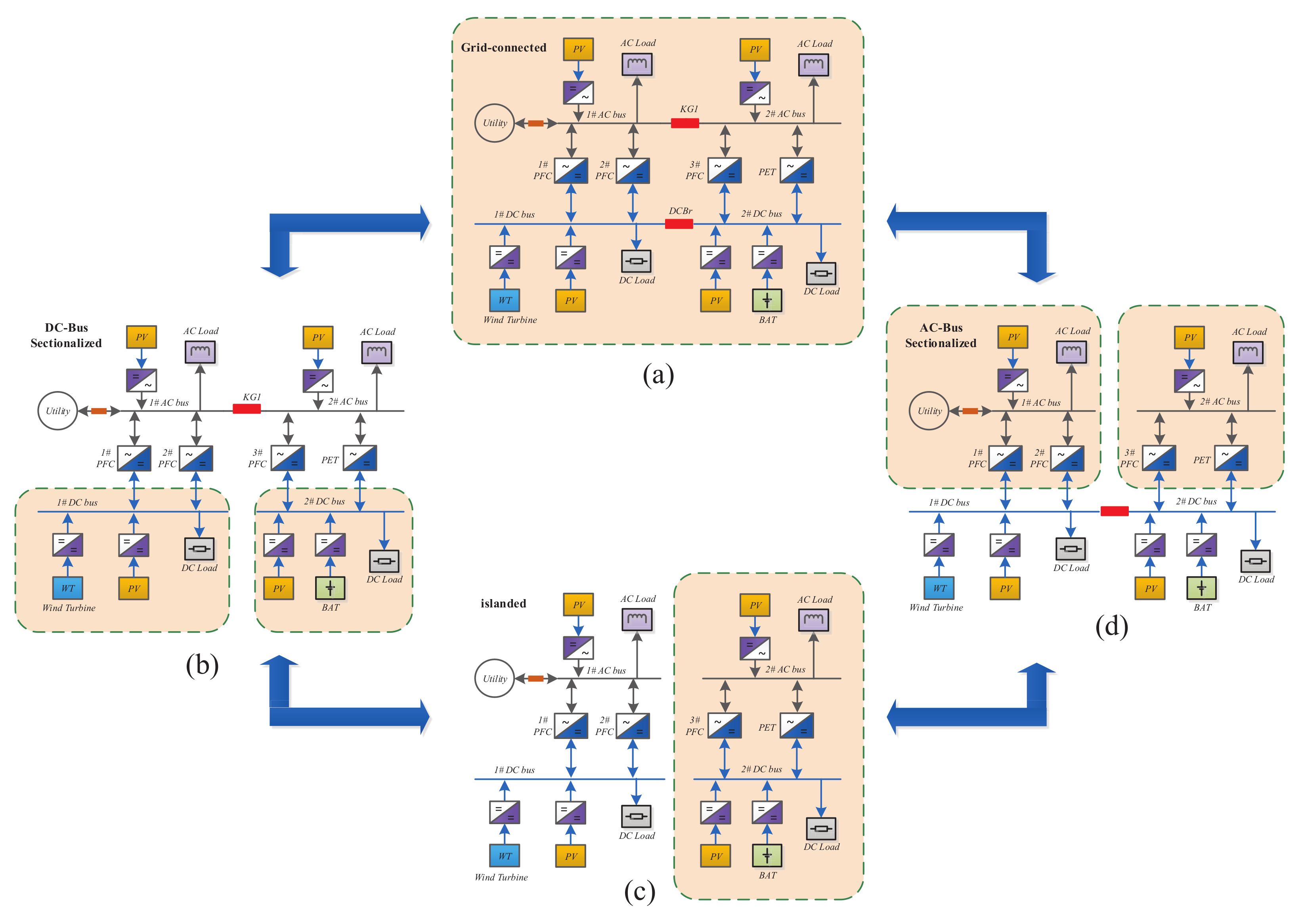
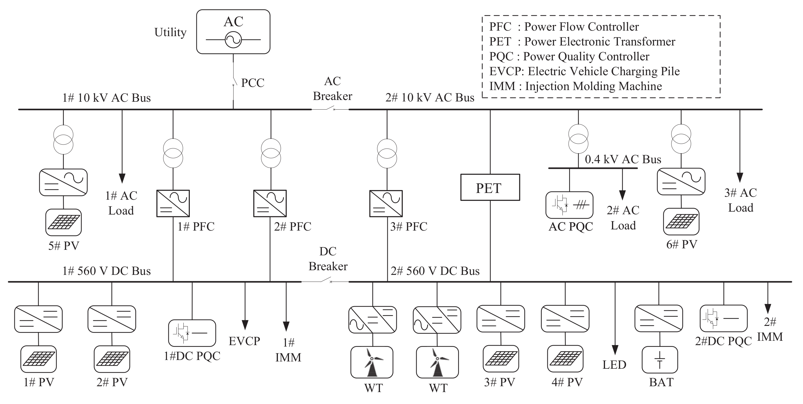
2.1. System Configuration
2.2. Multimode Operation
2.2.1. Grid-Connected Mode
2.2.2. AC-Bus Sectionalized Mode
2.2.3. DC-Bus Sectionalized Mode
2.2.4. Islanded Mode
3. Hierarchical Control of Bus-Sectionalized Hybrid AC/DC Microgrid
- The primary control level supports the DC-bus voltage regulation as well as the AC-bus voltage and frequency regulation.
- The secondary control level restores the DC voltage and AC voltage and frequency to their reference values. Proper power flow sharing schemes are also achieved among PFCs, the PET, and the battery storage.
- Seamless active or passive switching among the different operation modes are achieved through some active control strategies by the secondary control.
- The PFCs, PET, and the battery storage are not necessary to change their primary control configurations in different operation modes.
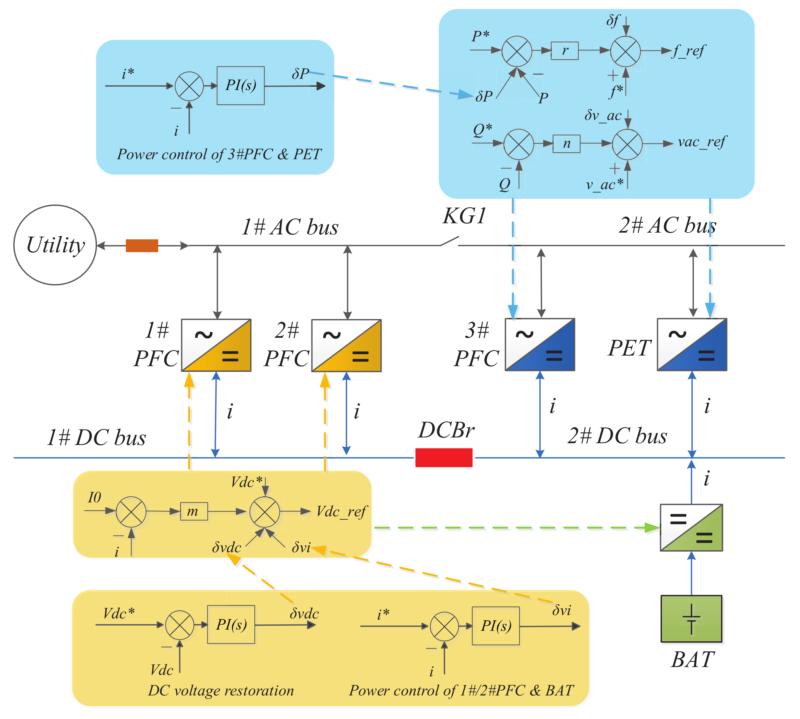
3.1. Primary Control
3.1.1. 1# PFC and 2 # PFC
3.1.2. 3# PFC
3.1.3. PET
3.1.4. Battery Storage
3.1.5. PV Sources
3.2. Secondary Control
3.2.1. Basic Control Principle
- (1)
- Power Flow Adjusting
- (2)
- AC Bus Regulating
- (3)
- DC Bus Regulating
- (4)
- PV Power Control
3.2.2. Multimode Operation
- (1)
- Grid-connected Mode
- Use (8) to regulate for 1# PFC and 2# PFC to restore the DC bus voltage. Calculate the average current () of (for 1# PFC) and (for 2# PFC) and use it as the current reference in (4) to share their output power. To ensure the secondary algorithm is compatible with the failure of certain equipments, the fault state (1 for normal and 0 for fault) of every converter is collected by the secondary controller and added into the calculation of current references, which is given aswhere and are the device states of 1# PFC and 2# PFC, respectively. Hereafter, the subscript of the term s indicates the state of device i, which can be 1, 2, or 3 for the PFCs or just the device names.
- Calculate the weighted average current of , , (for 3# PFC) and (for PET) and then use it as the current reference in (4) and (5) to share the power flow between 3# PFC and the PET, which can be expressed asIn this case, the weighted-average power flow of 3# PFC and the PET are forced to be equal with that of 1# PFC and 2# PFC.
- If both 1# PFC and 2# PFC are in fault, the battery storage now maintains the DC bus voltage and uses (8) to restore the DC-bus voltage deviation. In this case, the average current of , , and (for the battery storage) is calculated and utilized as the current references for 3# PFC and the PET, which is written asIn this case, the weighted power flow of the battery is forced to be equal with that of 3# PFC and the PET, which is aimed to reduce the their stress.
- If at least one of 1# PFC and 2# PFC works well, the battery storage adopts the SOC control. If the SOC exceeds its upper limit, or falls its lower limit, a specific positive or negative is assigned in (4) for the storage battery to discharge/charge itself. Otherwise, if the SOC is within the normal range, a ZERO will be fed into (4) to make the battery work in the floating mode.
- For each PV source, the power dispatching command are given as
- (2)
- AC Bus-sectionalized Mode
- Calculate the weighted average current of and , and then use it as the current reference in (5) for the PET to share the power flow between 3# PFC and the PET.
- If the SOC is in normal range, the battery storage helps to restore the DC-bus voltage to reduce the stress of 1# PFC and 2# PFC, as the fluctuation of the generation or the load consumption is taken by this three in this case.
- To realize the SOC control of the battery, the supervisory current reference for 1# PFC and 2# PFC is given asConsequently, the battery discharges/charges with the specified current if its SOC exceeds/falls below its upper/lower limit. In these two cases, the battery will not participate in the DC bus voltage restoration. Otherwise, the battery will maintain the DC bus voltage in the floating (ZERO power) mode, as well as restore it.
- For each PV source, the power dispatching command is given as
- (3)
- DC Bus-sectionalized Mode
- To realize the SOC control of the battery, the supervisory current reference for 3# PFC and the PET is given asConsequently, the battery discharges/charges with the specified current if its SOC exceeds/falls below its upper/lower limit. Otherwise, the battery will maintain the DC-bus voltage in the floating (ZERO power) mode.
- For PV sources connected to the 1# DC bus, the power dispatching command is given asFor PV sources connected to the 2# DC bus, the power dispatching command is given as
- (4)
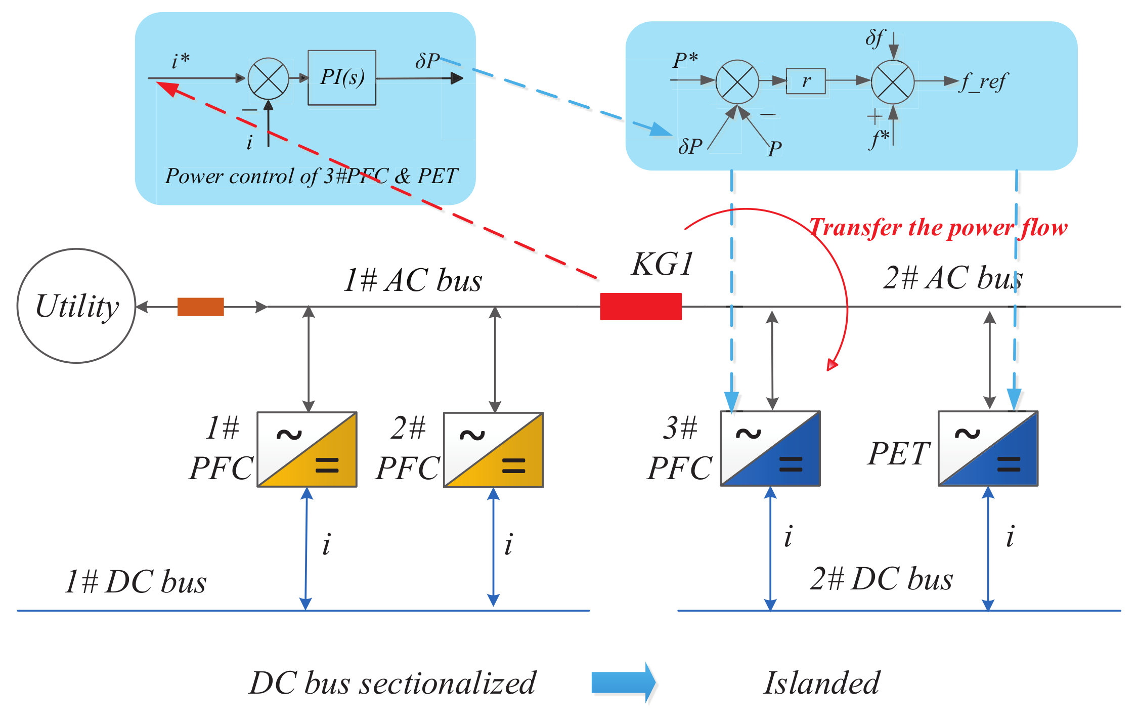
- Islanded Mode
- Use (8) to regulate for the battery to restore the 2# DC-bus voltage.
- Calculate the weighted average current of and , and then use it as the current reference in (5) for the PET to share the power flow between 3# PFC and the PET.
- For PV sources connected to the 1# DC bus, the power dispatching command is given asFor PV sources connected to the 2# DC bus, the power dispatching command is given as
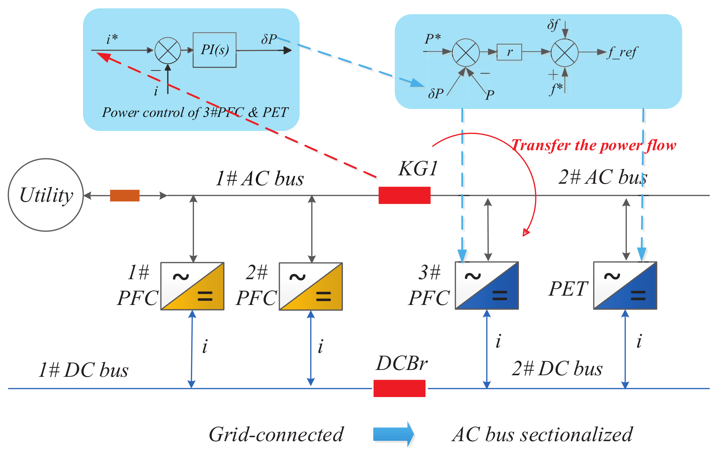
3.2.3. Seamless Mode Switching
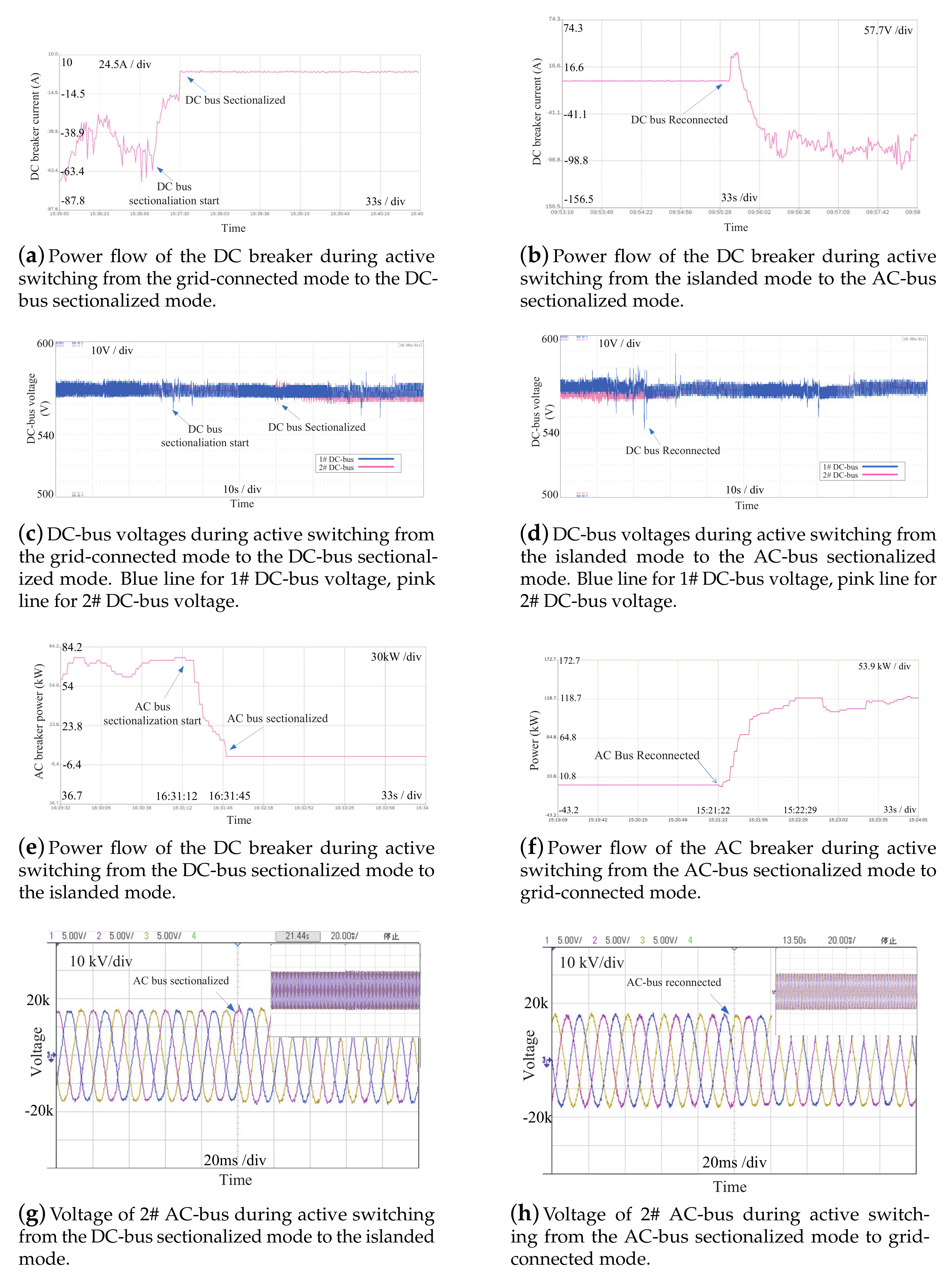
- (1)
- Switching from the grid-connected mode to the AC-bus sectionalized mode
- Calculate the weighted-average current of , , and , and use it as the current reference in (4) to share the output power among 1# PFC, 2# PFC, and the battery.
- Make 3# PFC and the PET to undertake the power flow of the AC breaker, so the current reference for 3# PFC and the PET is given aswhere is the current passing the AC breaker, with the positive direction defined as passing from 1# AC bus to 2# AC bus.
- If the passing power flow in the AC breaker meets the requirements of opening it. The AC breaker then receive the open command to execute the opening operation.
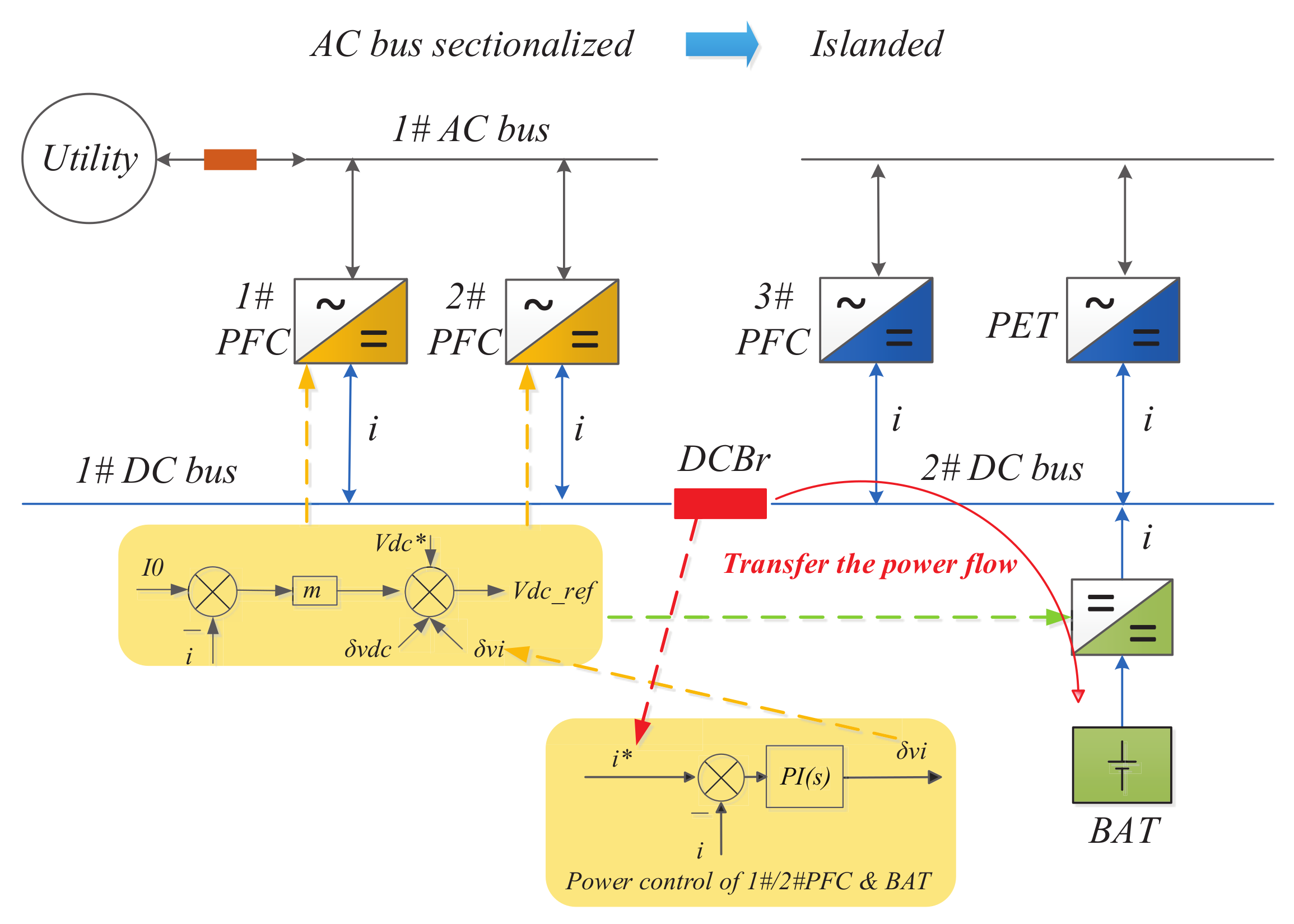
- (2)
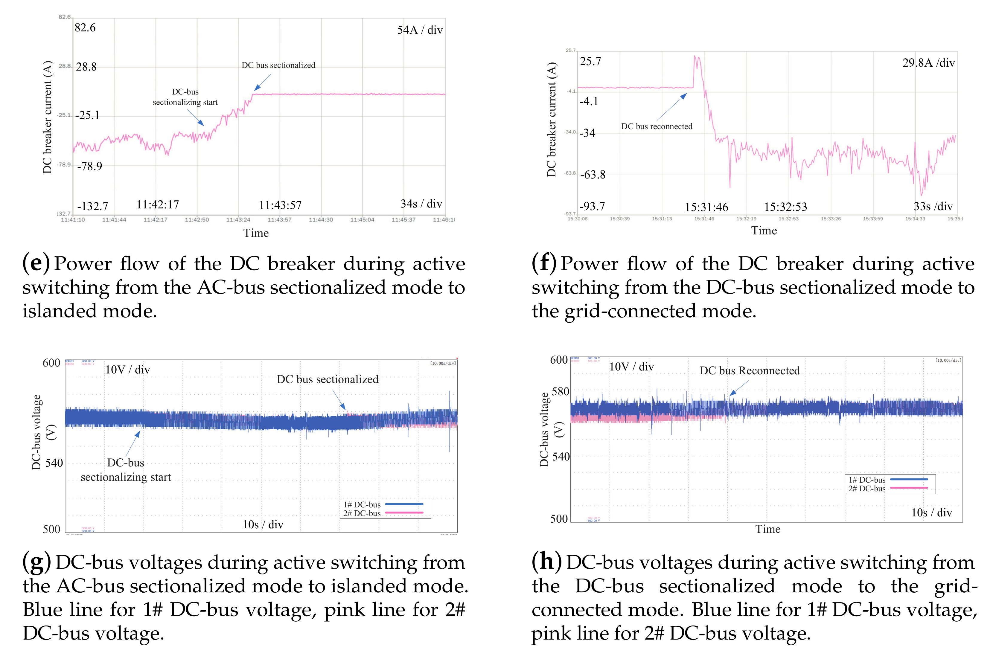
- Switching from the AC-bus sectionalized mode to the islanded mode
- Calculate the weighted average current of and and then use it as the current reference to share the power flow between 1# PFC and 2# PFC.
- Make the battery to undertake the power flow of the DC breaker, so the battery does not share its output power with 1# PFC and 2# PFC any more and the current reference for the battery is given aswhere is the current passing the DC breaker, with the positive direction defined as passing from 1# DC bus to 2# DC bus.
- If the passing power flow in the DC breaker meets the requirements of cutting off, the DC breaker then receives the open command to execute the opening operation.
- (3)
- Switching from the grid-connected mode to the DC-bus sectionalized mode
- Give the ZERO current reference for the storage battery to make it work in the floating mode.
- If the passing power flow in the DC breaker meets the requirements of cutting-off. The DC breaker then receive the open command to execute the opening operation.
- (4)
- Switching from the DC-bus sectionalized mode to the islanded mode
- The current reference for 3# PFC and the PET is given aswhere is the current passing the AC breaker, with the positive direction defined as passing from 1# AC bus to 2# AC bus.
- If the passing power flow in the AC breaker meets the requirements of opening it, the AC breaker then receives the open command to execute the opening operation.
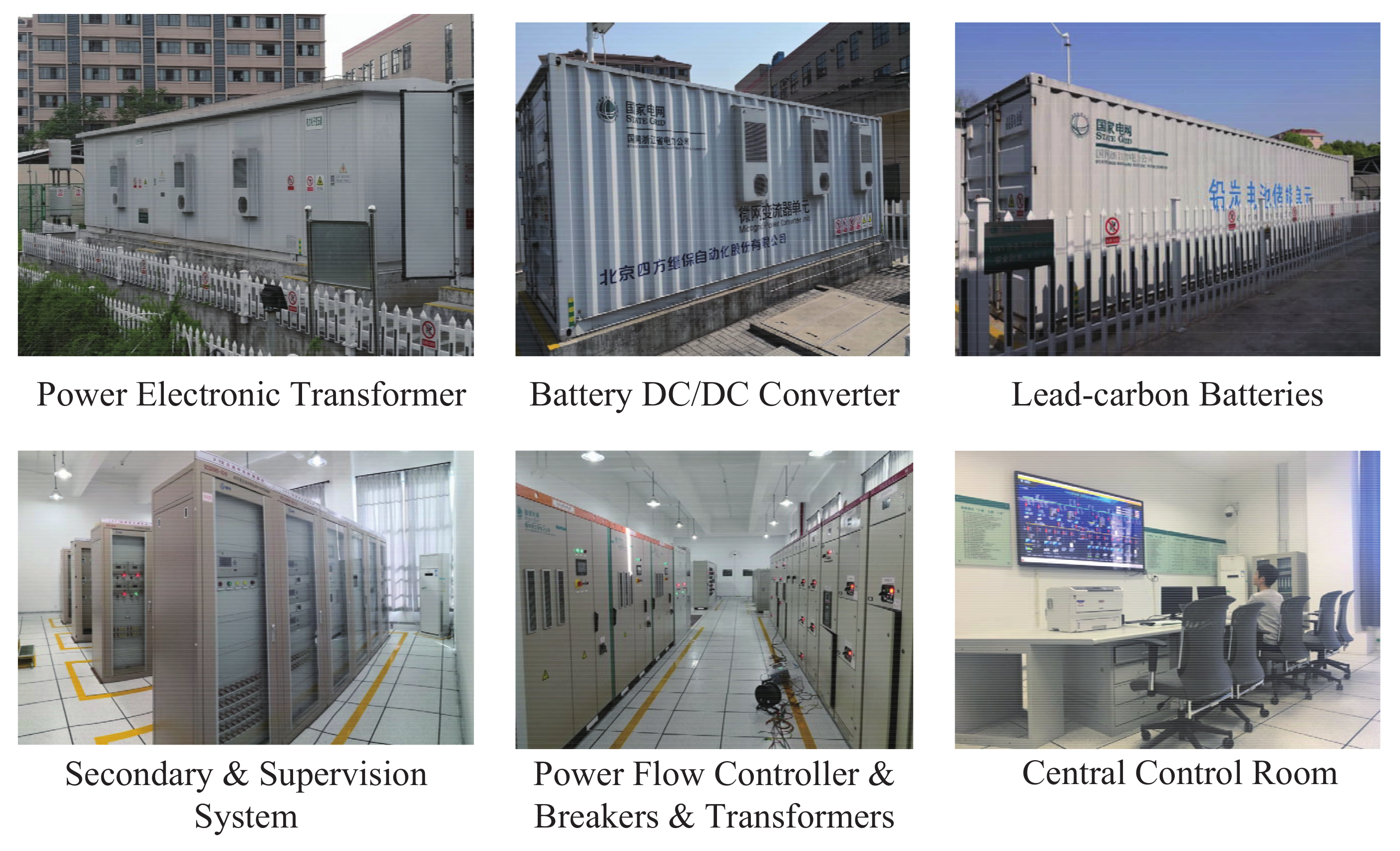
4. Experimental Study
4.1. System Configuration
4.2. Voltage Grade Set
- Economy: The insulation and protection of the 560 Vdc voltage grade is the same as that of the 380 Vac voltage grade. Thus, most of the current produced cables, breakers, and switches can be applied to the 560 Vdc voltage grade directly.
- Compatibility: Compatibility is a key factor of the 560 Vdc voltage grade. Currently, most of the power loads adopt the variable frequency drive technology. The realization of the direct DC power supply for these variable frequency drivers is the greatest advantage of DC distribution networks. The 560 Vdc voltage grade is compatibility with current DC voltage grade of most AC/DC/AC variable frequency drivers.
- Adaptability: Taking distributed generation into consideration, the 560 Vdc voltage grade can easily meet the need of 380Vac inversion. Thus, 560 Vdc fits the requirement for integration of PV sources and batteries very well.
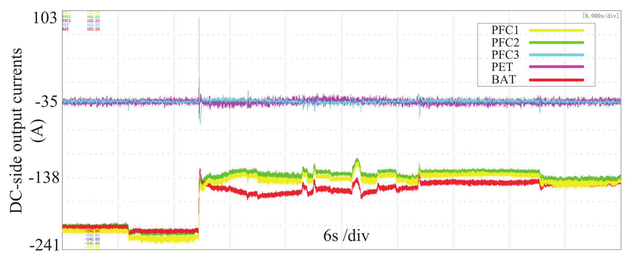
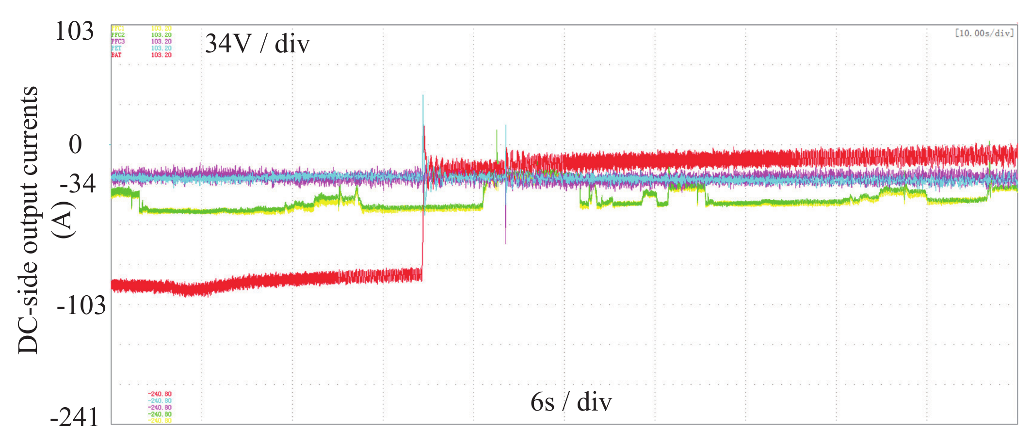
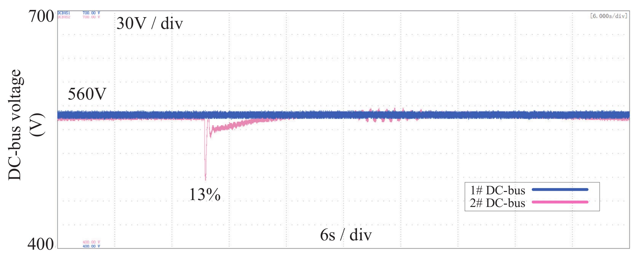
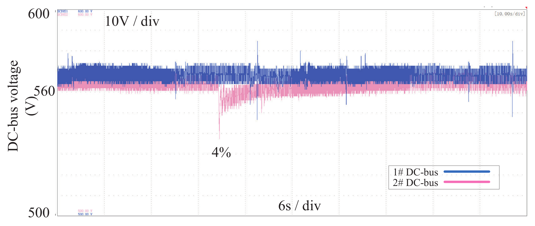
4.3. Multimode Operation Study
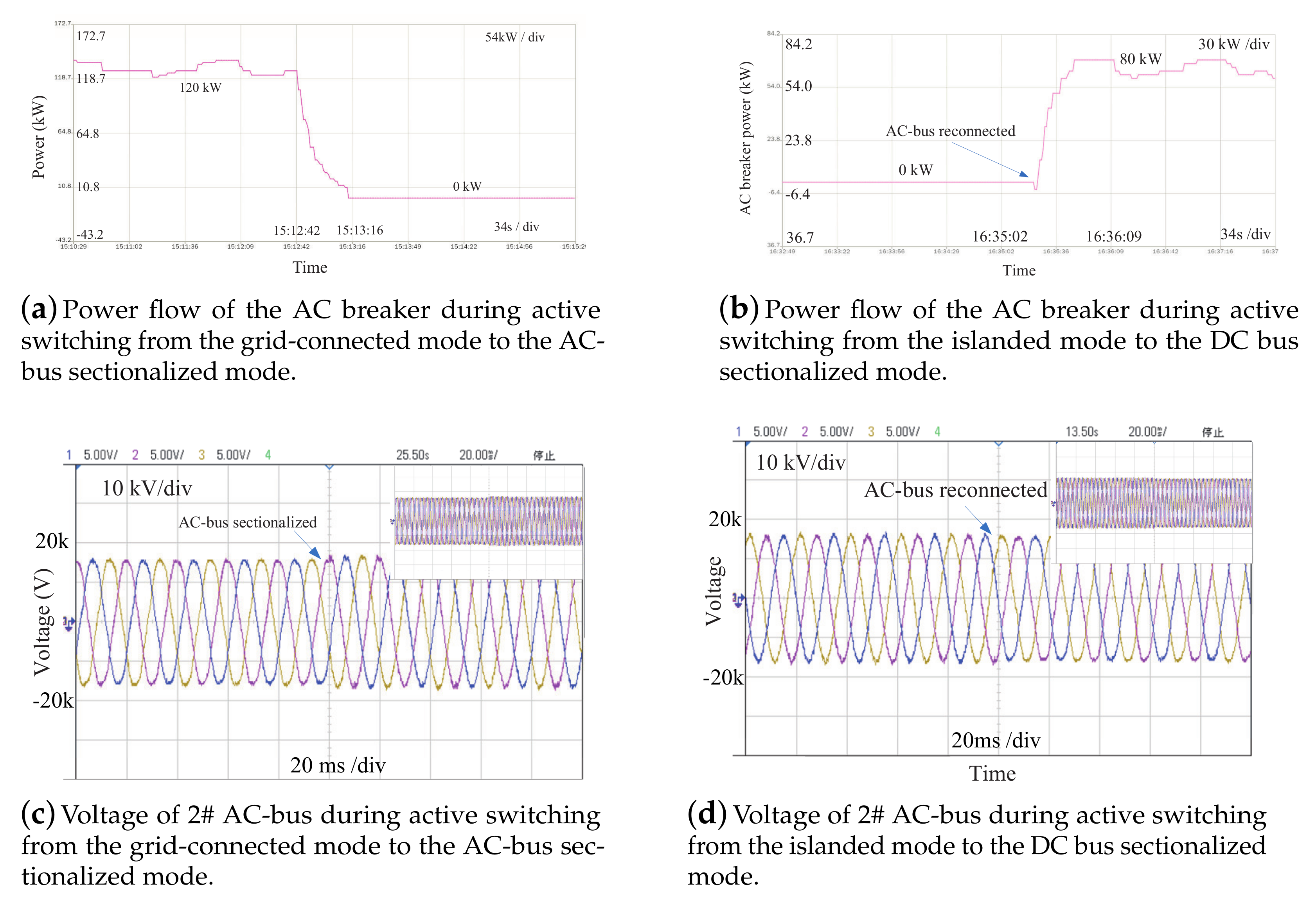
4.4. Seamless Mode Switching Study
5. Conclusions
Author Contributions
Funding
Institutional Review Board Statement
Informed Consent Statement
Data Availability Statement
Conflicts of Interest
Appendix A. Control Parameters

| Device | Function | Parameter |
|---|---|---|
| 1# PFC & 2# PFC | DC voltage restoration | kp = 0.0005, ki = 0.05 |
| DC current regulation | kp = 0.002, ki = 0.2 | |
| DC voltage droop coefficient | m = 0.04 | |
| 3# PFC | AC frequency regulation | kp = 0.001, ki = 0.1 |
| AC voltage regulation | kp = 0.00005, ki = 0.005 | |
| AC voltage droop coefficient | m = 0.00001 | |
| AC frequency droop coefficient | n = 0.000005 | |
| DC current regulation | kp = 0.002, ki = 0.2 | |
| PET | DC current regulation | kp = 0.002, ki = 0.2 |
| Storage | DC voltage restoration | kp = 0.001, ki = 0.1 |
| DC current regulation | kp = 0.002, ki = 0.2 |
References
- Huang, J.; Zhang, X.; Mao, T. Multi-time scale frequency regulation of a general resonant DC transformer in hybrid AC/DC microgrid. IEEE Trans. Ind. Electron. 2020. [Google Scholar] [CrossRef]
- Yang, P.; Yu, M.; Wu, Q.; Wang, P.; Xia, Y.; Wei, W. Decentralized economic operation control for hybrid AC/DC microgrid. IEEE Trans. Sustain. Energy 2020, 11, 1898–1910. [Google Scholar] [CrossRef]
- Zhou, Q.; Shahidehpour, M.; Li, Z.; Che, L.; Alabdulwahab, A.; Abusorrah, A. Compartmentalization strategy for the optimal economic operation of a hybrid AC/DC microgrid. IEEE Trans. Power Syst. 2020, 35, 1294–1304. [Google Scholar] [CrossRef]
- Gupta, A.; Doolla, S.; Chatterjee, K. Hybrid AC-DC microgrid: Systematic evaluation of control strategies. IEEE Trans. Smart Grid 2017, 9, 3830–3843. [Google Scholar] [CrossRef]
- Najafzadeh, M.; Ahmadiahangar, R.; Husev, O.; Roasto, I.; Jalakas, T.; Blinov, A. Recent contributions, future prospects and limitations of interlinking converter control in hybrid AC/DC microgrids. IEEE Access 2021, 9, 7960–7984. [Google Scholar] [CrossRef]
- Zhang, B.; Han, X.; Ren, C.; Zhang, D.; Wang, L.; Song, T. A circulating current suppression method with adaptive virtual impedance for multi-bidirectional power converters under unbalanced conditions. CSEE J. Power Energy Syst. 2020. [Google Scholar] [CrossRef]
- Loh, P.C.; Li, D.; Chai, Y.K.; Blaabjerg, F. Autonomous operation of hybrid microgrid with AC and DC subgrids. IEEE Trans. Power Electron. 2013, 28, 2214–2223. [Google Scholar] [CrossRef]
- Loh, P.C.; Li, D.; Chai, Y.K.; Blaabjerg, F. Autonomous control of interlinking converter with energy storage in hybrid AC/DC microgrid. IEEE Trans. Ind. Appl. 2013, 49, 1374–1382. [Google Scholar] [CrossRef]
- Peyghami, S.; Mokhtari, H.; Blaabjerg, F. Autonomous operation of a hybrid AC/DC microgrid with multiple interlinking converters. IEEE Trans. Smart Grid 2017. [Google Scholar] [CrossRef] [Green Version]
- Lu, X.; Guerrero, J.M.; Sun, K.; Vasquez, J.C.; Teodorescu, R.; Huang, L. Hierarchical control of parallel AC-DC converter interfaces for hybrid microgrids. IEEE Trans. Smart Grid 2014, 5, 683–692. [Google Scholar] [CrossRef] [Green Version]
- Wang, C.; Li, X.; Guo, L.; Li, Y.W. A nonlinear-disturbance-observer-based DC-bus voltage control for a hybrid AC/DC microgrid. IEEE Trans. Power Electron. 2014, 29, 6162–6177. [Google Scholar] [CrossRef]
- Liu, X.; Wang, P.; Loh, P.C. A hybrid AC/DC microgrid and its coordination control. IEEE Trans. Smart Grid 2011, 2, 278–286. [Google Scholar]
- Wang, J.; Jin, C.; Wang, P. A uniform control strategy for the interlinking converter in hierarchical controlled hybrid AC/DC microgrids. IEEE Trans. Ind. Electron. 2018, 65, 6188–6197. [Google Scholar] [CrossRef]
- Yang, P.; Yu, M.; Wu, Q.; Hatziargyriou, N.; Xia, Y.; Wei, W. Decentralized bidirectional voltage supporting control for multi-mode hybrid AC/DC microgrid. IEEE Trans. Smart Grid 2020, 11, 2615–2626. [Google Scholar] [CrossRef]
- Wang, L.; Fu, X.; Wong, M.C.W. Operation and control of a hybrid coupled interlinking converter for hybrid AC/lvdc microgrids. IEEE Trans. Ind. Electron. 2020, 68, 7104–7114. [Google Scholar] [CrossRef]
- Espina, E.; Cardenas-Dobson, R.; Simpson-Porco, J.W.; Saez, D.; Kazerani, M. A consensus-based secondary control strategy for hybrid AC/DC microgrids with experimental validation. IEEE Trans. Power Electron. 2021, 36, 5971–5984. [Google Scholar] [CrossRef]
- Esfahani, M.S.G.; Savaghebi, M. A decentralized control strategy based on v-i droop for enhancing dynamics of autonomous hybrid AC/DC microgrids. IEEE Trans. Power Electron. 2021, 36, 9430–9440. [Google Scholar]
- Biglarahmadi, M.; Ketabi, A.; Baghaee, H.R.; Guerrero, J.M. Integrated nonlinear hierarchical control and management of hybrid AC/DC microgrids. IEEE Syst. J. 2021. [Google Scholar] [CrossRef]
- Khalid, M. Discussion on “novel supervisory control method for islanded droop-based AC/DC microgrids”. IEEE Trans. Power Syst. 2020, 35, 4138. [Google Scholar] [CrossRef]
- Li, X.; Guo, L.; Li, Y.; Hong, C.; Zhang, Y.; Guo, Z.; Huang, D.; Wang, C. Flexible interlinking and coordinated power control of multiple DC microgrids clusters. IEEE Trans. Sustain. Energy 2018, 9, 904–915. [Google Scholar] [CrossRef]
- Lou, G.; Gu, W.; Wang, J.; Wang, J.; Gu, B. A unified control scheme based on a disturbance observer for seamless transition operation of inverter-interfaced distributed generation. IEEE Trans. Smart Grid 2018, 9, 5444–5454. [Google Scholar] [CrossRef]
- Kleftakis, V.; Lagos, D.; Papadimitriou, C.; Hatziargyriou, N.D. Seamless transition between interconnected and islanded operation of DC microgrids. IEEE Trans. Smart Grid 2017, 10, 248–256. [Google Scholar] [CrossRef]
- Nguyen, T.L.; Wang, Y.; Tran, Q.T.; Caire, R.; Xu, Y.; Gavriluta, C. A Distributed Hierarchical Control Framework in Islanded Microgrids and Its Agent-based Design for Cyber-Physical Implementations. IEEE Trans. Ind. Electron. 2020. [Google Scholar] [CrossRef]


| Device | Control Method | Adjustable Parameter | Function |
|---|---|---|---|
| 1# PFC 2# PFC | DC V-I droop | DC rated voltage DC rated current Droop Coefficient | DC-bus voltage restoration accurate current sharing power sharing ratio setting |
| 3# PFC | AC droop AC droop | AC rated frequency AC rated acitve power AC rated voltage AC rated reactive power | AC frequency restoration active power sharing AC voltage restoration Reactive power sharing |
| PET | PQ control | P command Q command | active power sharing Reactive power sharing |
| Battery Storage | DC V-I droop | DC rated voltage DC rated current Droop Coefficient | DC-bus voltage restoration accurate current sharing power sharing ratio setting |
| PV Source | Power Dispatching | MPPT Power dispatching | Maximum power point tracking power generation control |
| Abbreviation | Full Name | Capacity |
|---|---|---|
| 1# PFC 2# PFC 3# PFC | Power Flow Controller | 250 kVA 250 kVA 250 kVA |
| PET | Power Electronic Transformer | 250 kVA |
| 1# PV 2# PV 3# PV 4# PV 5# PV 6# PV | Photovoltaic Source | 96 kWp 235 kWp 270 kWp 270 kWp 520 kWp 520 kWp |
| BAT | Lead-carbon Batteries | 4 h 250 kW |
| 1# 1MM 2# 1MM | Injection Molding Machine Load | 5 * 50 kw 5 * 50 kW |
| EVCP | Electric Vehicle Charging Pile | 8 * 60 kW |
| 1# DC Pdc 2# DC Pdc | DC Power Quality Controller | 50 A |
| AC Pdc | Power Quality Controller | 150 A |
| 1# WT 2# WT | Wind Turbine | 5 kW 5 kW |
| LED | Light-emitting Diode | 50 kW |
Publisher’s Note: MDPI stays neutral with regard to jurisdictional claims in published maps and institutional affiliations. |
© 2021 by the authors. Licensee MDPI, Basel, Switzerland. This article is an open access article distributed under the terms and conditions of the Creative Commons Attribution (CC BY) license (https://creativecommons.org/licenses/by/4.0/).
Share and Cite
Li, J.; Cai, H.; Yang, P.; Wei, W. A Bus-Sectionalized Hybrid AC/DC Microgrid: Concept, Control Paradigm, and Implementation. Energies 2021, 14, 3508. https://doi.org/10.3390/en14123508
Li J, Cai H, Yang P, Wei W. A Bus-Sectionalized Hybrid AC/DC Microgrid: Concept, Control Paradigm, and Implementation. Energies. 2021; 14(12):3508. https://doi.org/10.3390/en14123508
Chicago/Turabian StyleLi, Jing, Hongda Cai, Pengcheng Yang, and Wei Wei. 2021. "A Bus-Sectionalized Hybrid AC/DC Microgrid: Concept, Control Paradigm, and Implementation" Energies 14, no. 12: 3508. https://doi.org/10.3390/en14123508