Article

A Diode-MMC AC/DC Hub for Connecting Offshore Wind Farm and Offshore Production Platform

1
Institute for Energy and Environment, University of Strathclyde, Glasgow G1 1XW, UK
2
Department of Electrical Engineering, Inner Mongolia University of Technology, Hohhot 010051, China
*
Author to whom correspondence should be addressed.
Energies 2021, 14(13), 3759; https://doi.org/10.3390/en14133759
Submission received: 26 May 2021 / Revised: 19 June 2021 / Accepted: 21 June 2021 / Published: 23 June 2021

Abstract

:
A diode rectifier-modular multilevel converter AC/DC hub (DR-MMC Hub) is proposed to integrate offshore wind power to the onshore DC network and offshore production platforms (e.g., oil/gas and hydrogen production plants) with different DC voltage levels. The DR and MMCs are connected in parallel at the offshore AC collection network to integrate offshore wind power, and in series at the DC terminals of the offshore production platform and the onshore DC network. Compared with conventional parallel-connected DR-MMC HVDC systems, the proposed DR-MMC hub reduces the required MMC converter rating, leading to lower investment cost and power loss. System control of the DR-MMC AC/DC hub is designed based on the operation requirements of the offshore production platform, considering different control modes (power control or DC voltage control). System behaviors and requirements during AC and DC faults are investigated, and hybrid MMCs with half-bridge and full-bridge sub-modules (HBSMs and FBSMs) are used for safe operation during DC faults. Simulation results based on PSCAD/EMTDC validate the operation of the DR-MMC hub.

1. Introduction

The global energy transition from fossil fuels to renewable and sustainable alternatives is accelerating, with increased interest in developing offshore wind energy. In Europe, the total installed offshore wind capacity has reached 22.1 GW in 2019 [1]. There has also been increased interest in offshore production platforms (e.g., oil and gas production plants), and the benefits of utilizing offshore wind power and onshore HVDC grid to supply the offshore oil/gas platform have been addressed to replace power generated by gas turbines for carbon reduction commitment [2]. As an efficient and clean form of storing energy, offshore hydrogen can be produced from offshore wind power through power-to-gas technology to accommodate a large amount of intermittent renewable energy in power network [3,4], which could be deployed at unused oil/gas platforms as a financially attractive solution [5]. The interests in offshore production platforms potentially lead to the needs of offshore converter stations with the capability of transmitting wind power to the electrical grid connected to onshore and offshore production platforms with different DC voltages. For example, a concept for integrating offshore wind farm and offshore hydrogen production (delivering power up to 400 MW) is proposed in [3], where the offshore wind power is transmitted to both the onshore power grid and an offshore hydrogen platform by the offshore converter stations at different DC voltage levels.
Due to lower investment, footprint and higher efficiency than other converters, modular multilevel converters (MMCs) and the diode rectifier (DR)-based HVDC transmission systems have been proposed for integrating offshore wind farms [6,7,8,9,10]. However, for the connection of offshore wind/production platform and onshore grid system, using only DRs is not suitable as they cannot separately control the power transmissions to multiple terminals. Thus, a hybrid configuration combining the uncontrolled DR and the fully-controlled MMC is likely required.
Parallel operation of MMC-HVDC and DR-HVDC systems to transmit power from offshore wind farms has been analyzed in [6]. The MMC regulates the offshore AC voltage to support the DR, rather than using distributed wind turbine converters with specific grid-forming control schemes [6,9]. However, the converter power rating of the MMC in this scheme can be quite high, considering the different operation requirements and conditions, leading to an increased cost.
Several hybrid HVDC solutions have been proposed to combine the advantages of different converter topologies. A hybrid scheme with a series-connected line-commutated converter (LCC), or a DR and MMC, has been proposed in which the MMC is used to maintain the AC voltage and frequency [11,12]. However, the hybrid is only dedicated to a single DC network. An MMC-based DC autotransformer (DC AUTO) has been considered for connecting the inner AC bus of the DC AUTO to an external AC system to achieve power exchange between the two DC networks and the AC system [13]. However, the operation control and fault ride-through operation when connecting with an offshore wind farm have not been investigated. A hybrid AC/DC hub composed of the LCC and MMC in series connection has been proposed for onshore wind-power integration and interconnection of two DC networks with different DC voltages [14], but this hub is not suitable for offshore applications due to the large footprint and heavyweight of the LCC, which also needs a strong AC grid for commutation.
To overcome the above challenges, a DR-MMC AC/DC Hub (DR-MMC Hub) with the DR and MMCs connected in parallel at the AC side, and in series at the DC side, is proposed to transmit offshore wind power to an onshore DC network and an offshore production platform with different DC voltage levels. The main contributions of this paper are as follows:
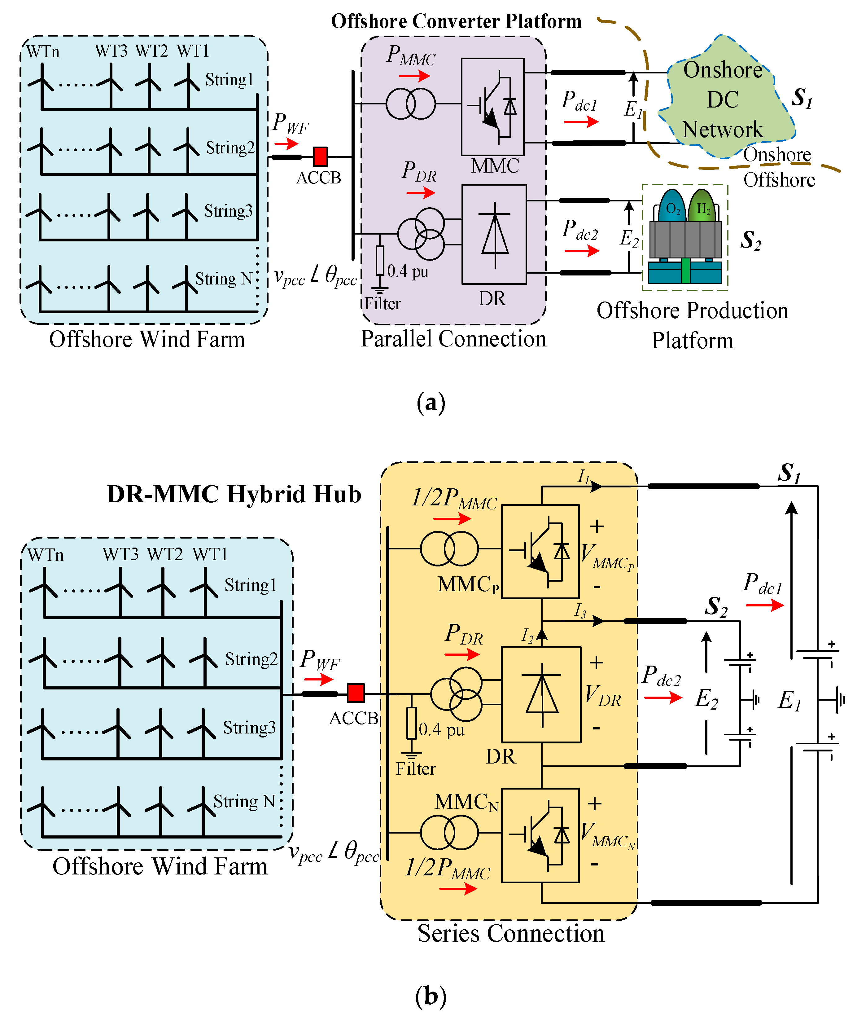
  • The proposal of a new DR-MMC Hub which enables part of the power from the DR to be transmitted to the onshore DC network directly, and thus reduces the size of the MMC and lowers the cost and power loss of the overall converter system when compared with the conventional approach using parallel DR and MMC.
  • Based on the operation requirement of the offshore production platform, comprehensive operating conditions of the proposed DR-MMC Hub are investigated, considering the different control modes (power control or DC voltage control).
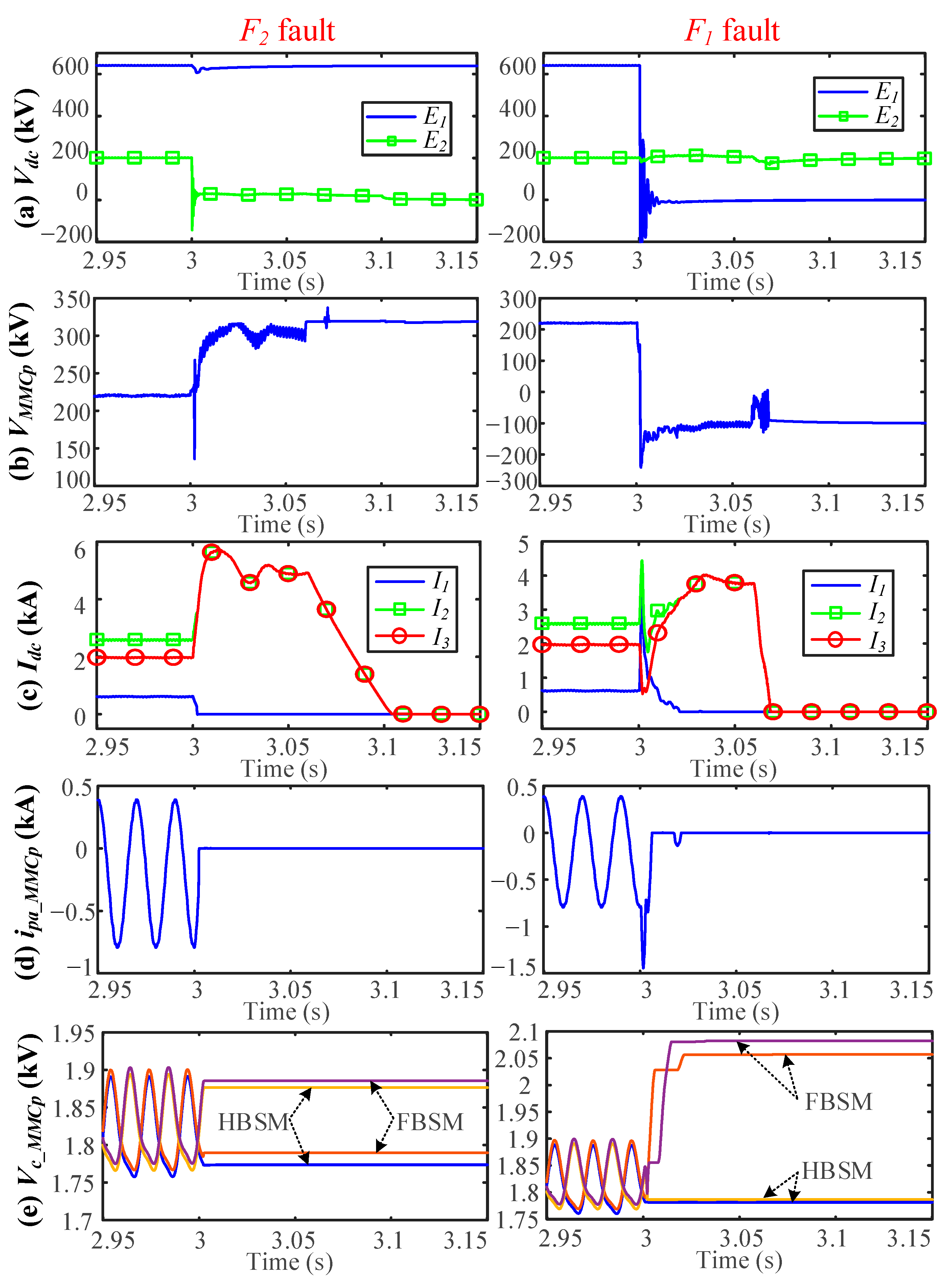
  • Detailed fault ride-through of the DR-MMC Hub and system design are analyzed. For AC faults, the hub can ride through them without adopting any specific protection schemes. For DC faults on either DC network, the hub can isolate them by introducing a hybrid MMC configuration.
The rest of this paper is organized as follows. The topology analysis of the DR-MMC Hub is depicted in Section 2, while Section 3 describes the system control principle of the DR-MMC Hub. A comprehensive AC/DC fault ride-through and converter power loss estimation of the DR-MMC Hub are analyzed in Section 4. Simulation verifications of the DR-MMC Hub during normal operation, and AC and DC faults are given in Section 5. Finally, conclusions are summarized in Section 6.

2. Topology and Efficiency Analysis

2.1. Envisaged Operation Scenario

The envisaged operation scenario is illustrated in Figure 1a, where the offshore converter with parallel-connected MMC and DR, transmits wind power to the onshore DC network (S1) and the offshore production platform DC network (S2), with different DC voltages of E1 and E2 (E1 > E2) respectively. The MMC transmits the generated wind power Pdc1 to S1 and reverses power to feed S2 under low/no wind conditions. The wind power Pdc2 is transmitted to S2 by the DR. The produced oil/gas or hydrogen is transported through pipelines or shipped to land.

2.2. DR-MMC Hub Configuration

Figure 1b depicts the topology of the DR-MMC Hub in a symmetrical monopole setup. The proposed topology is mainly composed of a DR and two MMCs (MMCP and MMCN) in series connection.
If power transferring from the offshore wind farm to S1 and S2 is defined as positive, the ratios of the DC voltages E2 and E1 and the power transfer Pdc1 and Pdc2 can be expressed as:
{ m = E 2 / E 1 ,   0 < m < 1 , α = P d c 1 / P d c 2 ,   α > 0 ,
where Pdc1 and Pdc2 are the active power transmitted to S1 and S2, respectively.
Assuming the power losses on converters and transmission lines are negligible, the total transmitted power from the offshore wind farm is:
P W F = P d c 1 + P d c 2 = ( 1 + α ) P d c 2 .
The DC current at the DR (I2) is the sum of the DC currents of DC networks S1 (I1) and S2 (I3), as:
I 2 = I 1 + I 3 = ( P d c 1 / E 1 + P d c 2 / E 2 ) .
Assuming the voltage drops on the DC lines are low, and can be neglected, the DC voltage of the DR and the sum of the two MMCs’ DC voltages are:
V D R = E 2 ,   V M M C = V M M C P + V M M C N = E 1 E 2 .
Consequently, the total active power of the two MMCs in the DR-MMC Hub is:
P M M C h y b r i d = V M M C I 1 = ( E 1 E 2 ) P d c 1 E 1 = ( 1 m ) P d c 1 = ( α α m ) P d c 2 = α     α m 1   +   α P W F .
Similarly, the active power of the DR is:
P D R h y b r i d = V D R I 2 = E 2 ( P d c 1 E 1 + P d c 2 E 2 ) = m P d c 1 + P d c 2 = ( m α + 1 ) P d c 2 = m α   +   1 1   +   α P W F .
If the conventional parallel system shown in Figure 1a is used, the converter power ratings of the MMC and the DR are:
{ P M M C _ c o n = P d c 1 = α P d c 2 > P M M C _ h y b r i d , P D R _ c o n = P d c 2 < P D R _ h y b r i d .
The converter power ratings of the MMC and DR in different system configurations are shown in Figure 2. Figure 2a indicates that the converter power rating of the MMCs in the DR-MMC Hub is smaller than that in the parallel-connected configuration shown in Figure 1a, especially when the voltage ratio m is high (close to 1). In contrast, as shown in Figure 2b, the DR power rating of the proposed system is higher than that of the conventional parallel system. For example, in a ±100 kV/±320 kV DR-MMC Hub transferring 400 MW Pdc1 and 400 MW Pdc2 (i.e., m = 0.3125 and α = 1), the required power ratings of the MMC and DR are 275 MW and 525 MW, respectively, compared to 400 MW and 400 MW in the parallel connection design. Therefore, the overall efficiency and cost of the DR-MMC Hub are superior to the conventional parallel system as the power loss and cost of the DR for high power schemes are much lower than that of the MMC [8,9].

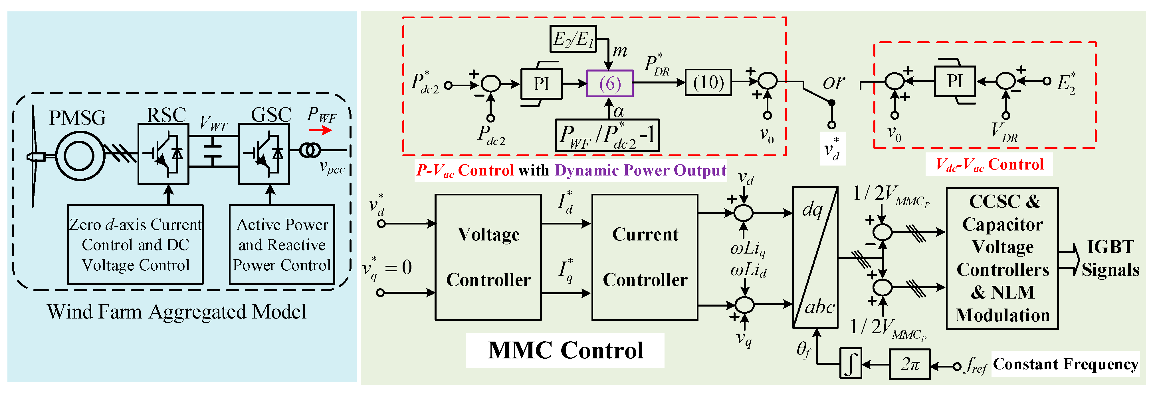
3. System Control Principle

Figure 3 shows the control structure of the DR-MMC Hub. An aggregated wind turbine model is considered, where the rotor-side converter (RSC) controls the DC-link voltage while the grid-side converter (GSC) regulates the active and reactive power [7]. The reactive power of the wind farm is set to be zero in the study, and reactive power compensation is provided by the MMCs of the offshore hub.
For the offshore hub shown in Figure 1b, a 12-pulse DR converter with AC filters is used, while hybrid MMCs with HBSMs and FBSMs are adopted for MMCP and MMCN. The details on the need for FBSMs will be discussed later in the paper. The MMCs in the offshore hub operate in grid-forming mode to control the offshore AC network with desirable voltage amplitude and frequency [15]. As shown in Figure 3, the reference of the q-axis voltage v q * is set to be zero, and the local frequency at the point of common coupling (PCC) is set to be a constant value (e.g., 50 Hz), while the reference of the d-axis voltage v d * is regulated as described late in the paper.
The control target of the DR-MMC Hub is to distribute the offshore wind farm power (PWF) to the two DC systems (i.e., Pdc1 and Pdc2). If Pdc2 is determined by the offshore production platform, the DC voltage of the DR should be maintained at a constant value, which is given as [6]:
V D R = 6 π ( 3 T D R v P C C P D R X D R V D R ) ,
where the turn ratio and reactance of the DR transformer are denoted as TDR and XDR. VDR and VPCC are the DC voltage of the DR and the PCC voltage, respectively.
If the offshore production platform controls the DC voltage of the network S2, Pdc2 should be controlled by the DR. Based on (2) and (6), the relationships between active power, m and α are:
{ P d c 1 = P W F P d c 2 , P d c 2 = P D R 1   +   m a , a = ( P W F / P d c 2 ) 1 .
From (9), the DC voltage ratio is fixed and the power transfer ratio is varied with the changes of PWF and Pdc2. Under low wind conditions, when the wind farm output is insufficient for the offshore production platform, the power from the onshore HVDC network is reversed through the MMCs. The active power of the DR is expressed as [16]:
P D R = 2 T D R E 2 X D R v P C C π E 2 2 6 X D R .
From (8) and (10), the DR’s DC voltage and active power are largely determined by the AC voltage VPCC.
Based on the alternative control targets of the offshore production platform as previously described, i.e., DC voltage (VDR) control or active power (Pdc2) control, the offshore voltage amplitude v d * is generated with different outer loops. When the offshore production platform behaves like a passive load, the DC voltage of S2 is determined by the DR through the control of the MMCs. In this case, the Vdc-Vac loop controls the DC voltage of the DR to the reference value E2, where the DC voltage error at S2 sets the offshore AC voltage reference. When the DC voltage of the offshore production platform is controlled by S2, e.g., by other energy storage devices in S2, the power transmitted to S2 needs to be controlled. In this event, the P-Vac control loop is implemented to regulate Pdc2, where the power output P D R * is dynamically regulated by the desired power reference P d c 2 * and the variation of PWF to produce the offshore AC voltage reference. A set-point v0 is added to keep the offshore AC voltage in the range of 0.9 to 1 p.u. for both cases, as shown in Figure 3. The circulating current suppression control (CCSC), capacitor voltage control and modulation methods which were investigated in [17,18] will not be discussed in this paper.

4. Fault Ride-Through and Power Loss Estimation

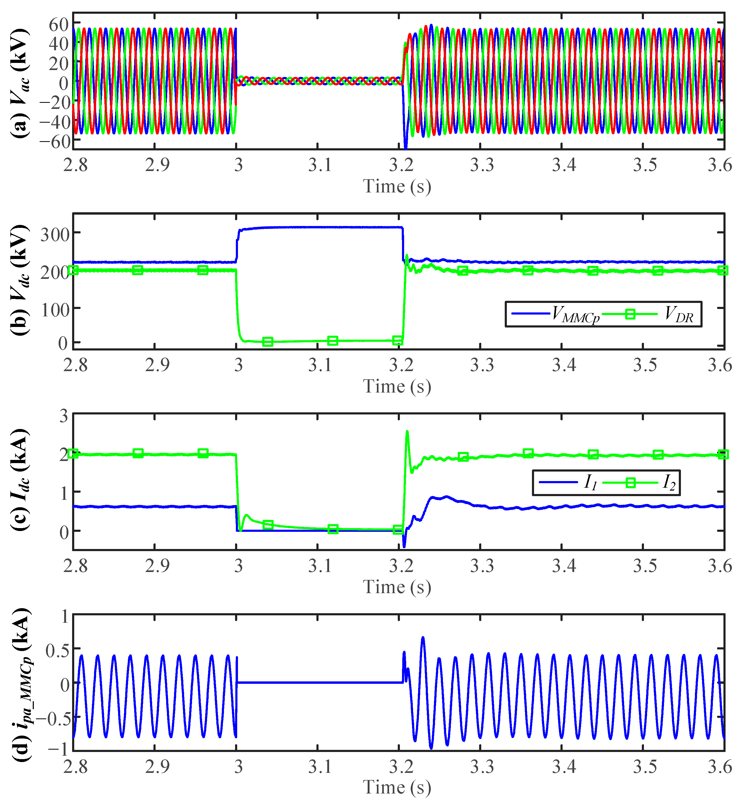
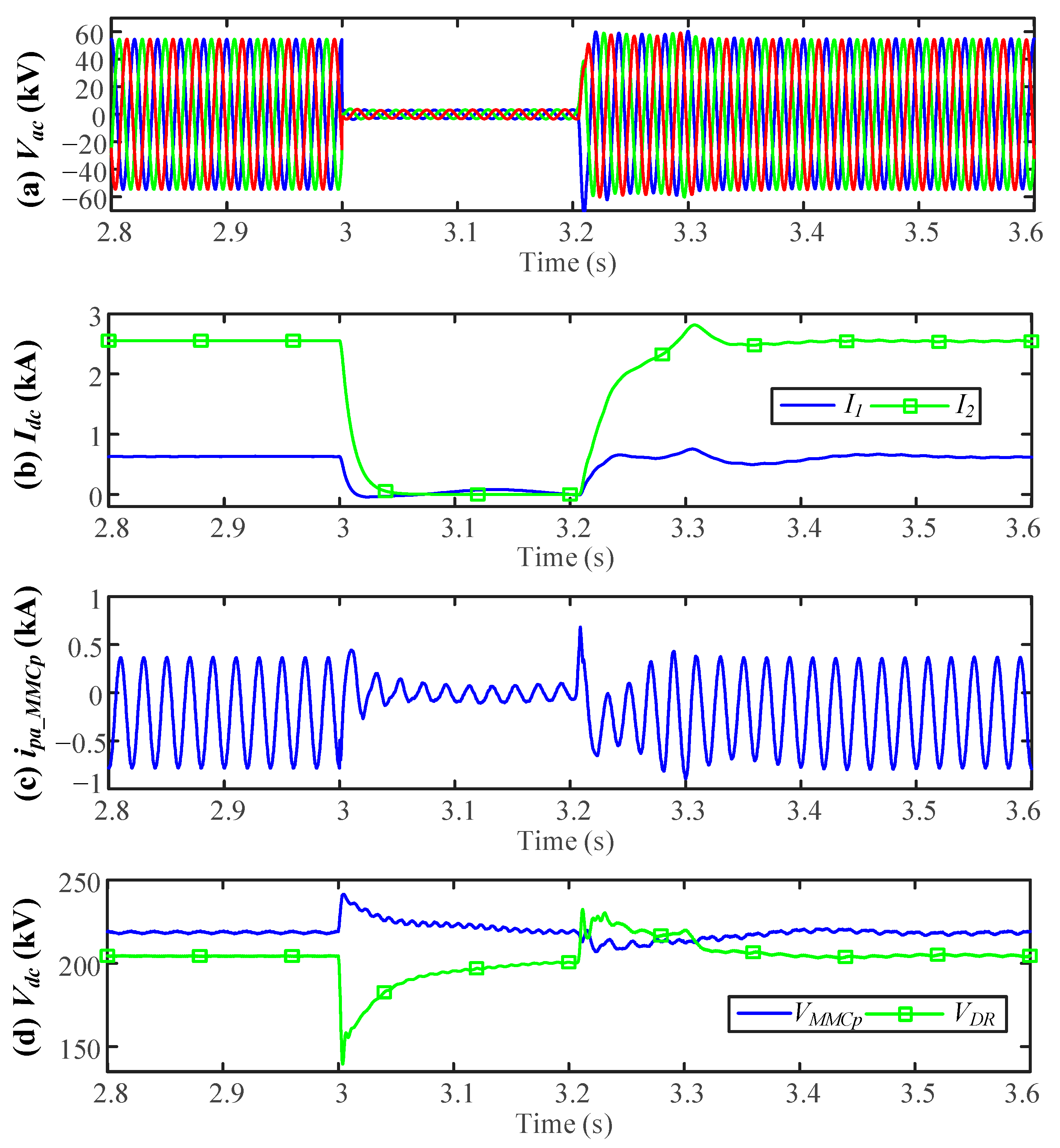
4.1. AC Fault Ride-Through

The response of the DR-MMC Hub and the offshore wind farm during various AC faults in different operation scenarios are presented in this subsection.
An offshore AC fault leads to a significant reduction of the offshore AC voltage and current-limiting operation of the wind turbine converters [19]. There is no active power transmitted from the DR station, of which conduction is blocked when the AC voltage becomes lower than the minimum DR conduction voltage (i.e., π E 2 / 6 2 T D R ).
If the offshore production platform behaves as a passive load, and E2 is controlled by the MMCs, the DC voltage collapses with the decrease of the offshore AC voltage, behaving like a pole-to-pole (p2p) DC fault at the S2 network. Therefore, the MMCs should be blocked immediately to support the DC voltage E1, as detailed in Section 4.2. After fault clearance, the system recovers to the normal operation quickly once the MMCs are re-enabled.
If the MMCs control the DC power of S2, although the offshore AC voltage decreases quickly during the AC fault, E2 is maintained at the rated value by the offshore production platform. No active power is being transmitted through the MMCs or the DR. For the MMCs in the offshore hub, the fault current in the AC fault cases is limited without disturbing DC side performance due to the inner current control loop, which has been well researched in [20]. After the AC faults, the system is restored rapidly with the recovery of the AC system voltage.

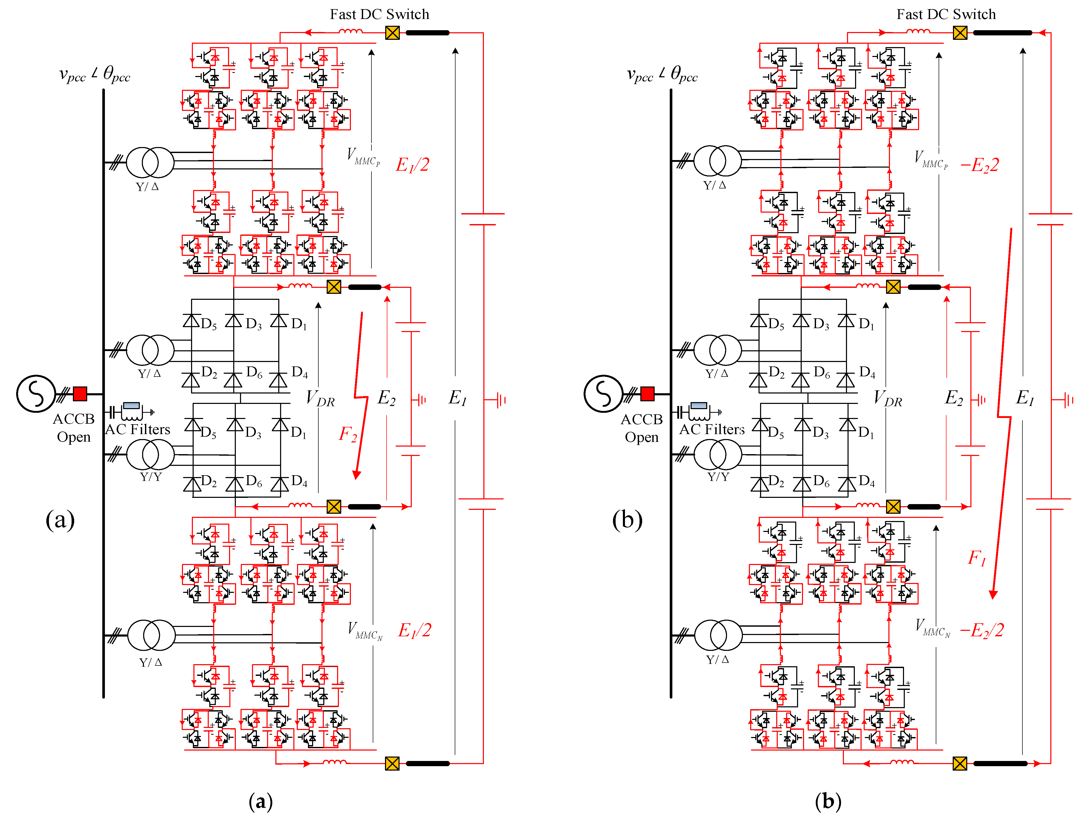
4.2. DC Fault Ride-Through

P2p DC faults in DC networks of S1 and S2 are considered. If a DC fault occurs on either DC network, the healthy DC side feeds the fault current into the faulty DC side through the MMC due to its direct electrical connection [13,14]. On account of the expensive cost and large volume relative to ACCBs at comparable voltages, high-voltage DC circuit breakers (DCCBs) are not considered in the offshore scheme to interrupt the DC faults [21,22].
In the event of a p2p fault happening at S2 (F2), the MMCs must provide the full DC voltage E1 to break the fault current from S1. During an F2 fault, the fault current path of the blocked MMCs in the DR-MMC Hub is shown in Figure 4a. The fault current path (shown in red) indicates that all SM capacitors of the MMCs are charged by the DC voltage E1. The fault current during F2 fault can be isolated as long as the total charged SM capacitor voltages in both MMCP and MMCN are higher than E1/2.
The required SM capacitor voltage ( V a r m _ M M C * ) in each arm for isolating an F2 fault, and the nominal SM capacitor voltage ( V a r m _ M M C * ) of the MMCs are calculated as:
{ V a r m _ M M C * = E 1 / 4 , V a r m _ M M C = ( 1 m ) E 1 / 2 .
If V a r m _ M M C * > V a r m _ M M C * (i.e., m > 1/2), additional HBSMs are required for each arm of the MMCs to withstand the voltage of E1/4 to avoid overcharging SM capacitors.
If a p2p fault happens at S1 (F1), the full DC voltage E2 should be withstood by the MMCs. Thus, FBSMs are required to replace some HBSMs in MMCs to isolate the fault current from S1. As shown in Figure 4b, the HBSMs will be by-passed during F1 fault. The fault current from S2 during F1 fault can be blocked as long as the total charged capacitor voltages of the FBSMs in MMCP and MMCN are higher than E2/2. The required capacitor voltage ( V a r m _ F B S M * ) of the total FBSMs in each arm to isolate F1 fault is given as:
V a r m _ F B S M * = E 2 / 4 = m E 1 / 4 .
If the SM number of each MMC arm without fault considerations is denoted as N S M , according to (11) and (12), the required FBSMs ( N F B * ) and HBSMs ( N H B * ) numbers in the hybrid MMCs for isolating DC faults can be calculated as:
N F B * = m 2 2 m N S M , N H B * = { 2 3 m 2 2 m N S M , m 1 / 2 , 1 2 N S M , 1 / 2 < m < 1 .
From (13), the insulated-gate bipolar transistor (IGBT) device cost per MVA in the MMCs increases compared to the HB-MMCs without fault consideration. Taking a ±100 kV/±320 kV DR-MMC Hub as an example, to safely isolate the DC faults, the required number of FBSMs and HBSMs in the hybrid MMCs are approximately 0.23NSM and 0.77NSM, respectively. Considering the cost of a FBSM is 1.5 times that of an HBSM, the IGBT device cost per MVA of the hybrid MMCs with DC fault blocking capabilities is 1.115 times the HB-MMC base value. However, even taking this into consideration, the proposed DR-MMC Hub still requires fewer switching devices (i.e., IGBTs) when compared to the conventional design outlined in Section 2.
Once a DC fault is detected, the MMCs that regulate the offshore AC voltage and frequency are blocked immediately to isolate the fault current from the AC to the DC side. Consequently, power transmission from the offshore AC network to the DC side is interrupted. If the offshore wind turbines are controlled in such a way that they continue generating active power, the surplus wind power increases the offshore AC voltage. Consequently, overcurrent could occur in the DR. Thus, after blocking the MMCs, the ACCB that connects the offshore wind farm and the DR-MMC Hub is opened to interrupt the potential overcurrent of the DR from the AC side.
When the DC current is reduced to near zero (<10 A) by blocking the MMCs, the fast DC switches on and the faulty part can be opened with the help of a selected DC fault detection algorithm. The DR-MMC Hub and offshore wind farm are then isolated from the DC fault point until fault clearance.

4.3. Valve Power Losses Estimation

The power losses in the proposed DR-MMC Hub are estimated considering the losses of the DR, HBSMs and FBSMs denoted as η D R , η H B and η F B . Thus, the estimated power losses of the conventional parallel system can be obtained as:
η c o n = η H B P d c 1 + η D R P d c 2 P W F .
The estimated power losses of the DR-MMC Hub are:
η h y b r i d = ( η F B N F B * N S M + η H B N H B * N S M ) P M M C _ h y b r i d + η D R P D R _ h y b r i d P W F .
References [8,23] indicate that the valve power losses of the DR, HBSMs and FBSMs are approximately 0.11%, 0.6% and 1.1%, respectively. Table 1 compares the two different configurations in a ±100 kV/±320 kV system transferring 400 MW Pdc1 and 400 MW Pdc2. Although FBSM-based MMCs have higher power losses than MMCs with HBSMs only, the estimated power loss of the DR-MMC Hub is only 0.3175%, whereas the power loss of the offshore converter system in parallel connection is approximately 0.355%. Furthermore, the ability of the DR-MMC Hub to block DC fault indicates the potential use of low-cost DC switch/disconnectors for DC line protection, rather than using expensive DC circuit breakers.

5. Simulation Verifications

The system shown in Figure 1b is modeled using PSCAD/EMTDC. The DC voltages are ±100 kV/±320 kV, and the DC power transmitted to S1 and S2 (Pdc1 and Pdc2) are both 400 MW. The DC cables in S1 (100 km) and S2 (50 km) are modeled using the frequency-dependent model in PSCAD/EMTDC. Fast DC switches are installed between the converters and DC cables.
The simulated system parameters are shown in Table 2. The hybrid MMC adopts the equivalent averaged model to improve simulation efficiency [24]. The simulation results of the MMCP and MMCN are the same due to the symmetrical monopole topology of the proposed system and, therefore, only the results of the MMCP are provided here. The DC voltages of S1 and S2 are given at the rated value when the MMCs operate in P-Vac control mode. If the MMCs operate in Vdc-Vac control mode, the DC voltage source in S2 is replaced by a passive load.

5.1. Operation in Vdc-Vac Control Mode

Figure 5 shows the normal operation of the DR-MMC Hub during power variation between the offshore production plant (Pdc2) and offshore wind farm (PWF). Initially, PWF is 0 and ramped up to the rated value of 800 MW from 2.0 s to 2.5 s. The initial power demand of the offshore production platform (Pdc2) is set at zero, and is stepped to the rated value of 400 MW at 1.5 s by connecting a passive load to E2.
Figure 5a shows that the DC voltage of S2 is well controlled by the MMCs throughout the power and load variations. According to Figure 5b,c, no power is transmitted from the offshore wind farm to S1 or S2 initially. When the passive load at S2 is connected at 1.5 s, the DC power Pdc2 is stepped to 400 MW, which is provided by the power reversed from S1 through the MMCs. When the active power of the offshore wind farm is gradually increased at 2.0 s, the infeed power from S1 to S2 is reduced accordingly. After the wind power becomes higher than the DC power Pdc2, the surplus power is transmitted to S2, as can be seen in Figure 5b.
The active and reactive power of the DR and MMCP shown in Figure 5c,d (MMCN is identical, thus not shown here) follow the system power change smoothly, and the offshore wind farm reactive power is well regulated at zero. To maintain the DC voltage of S2, the MMCs regulate the common bus AC voltage (shown in the RMS value in Figure 5e, and is varied with the change of PDR).

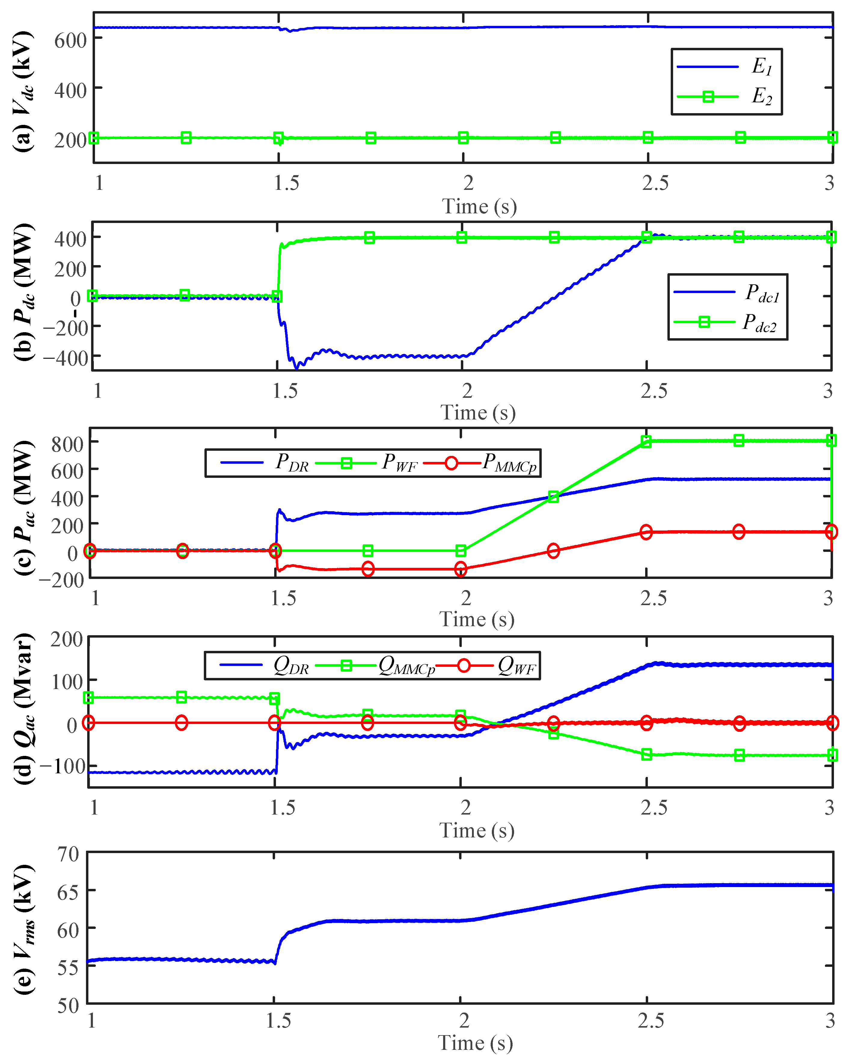
5.2. Operation in P-Vac Control Mode

Figure 6 illustrates the normal operation of the DR-MMC Hub with the MMCs operating in P-Vac control. Pdc2 is ramped up from 0 MW at 1 s, and to the rated value of 400 MW at 1.5 s, while PWF is ramped up from 0 MW at 2.0 s, to the rated value at 2.5 s and then ramped down by 0.15 p.u. (120 MW) from 3 s to 3.1 s. As a result, Figure 6a,b show that Pdc2 is well controlled throughout the power variations. While PWF remains at 0.85 p.u. (680 MW), and the power reference P d c 2 * shown in Figure 6d is dropped by 0.25 p.u. (100 MW) from 3.5 s to 3.6 s. PDR is decreased whereas PMMCp and Pdc1 are increased, so that the overall power is balanced.
Similar to Figure 5d, the smooth reactive power exchanges of the DR and MMCP are shown in Figure 6c, and the zero reactive power from the offshore wind farm is set by the control objective in the simulation study.
Figure 6d shows the power references P D R * and P d c 2 * from the outer controller of the MMCP, where P D R * is varied due to the variation of P d c 2 * and PWF. As shown in Figure 6e, the common bus AC voltage is controlled by the MMCs in accordance with the required PDR transmission.

5.3. AC Fault Ride-Through

Figure 7 shows the system performance during offshore AC faults in Vdc-Vac operation, while Figure 8 shows the corresponding response in P-Vac control. During the studies, a 200 ms three-phase to ground fault occurs at 3.0 s.
As shown in Figure 7a,b, when the DR-MMC Hub operates in Vdc-Vac control, the DC voltage of the DR is quickly decreased to zero after the occurrence of the AC fault. MMCP and MMCN are blocked immediately and their SM capacitors support the DC voltage E1. Consequently, each of the MMC DC terminal voltage increase from 220 kV to 320 kV, as can be seen in Figure 7b, while Figure 7c shows that the DC currents of MMCP (I1) and the DR (I2) are rapidly reduced to zero during the AC fault. Once the fault is cleared, MMCP and MMCN are re-enabled to restore the DC voltages of the MMCs and the DR, and the DC currents return to the prefault values. Figure 7d shows the upper arm current of MMCP, and no overcurrent is observed during the AC fault.
When the DR-MMC Hub operates in P-Vac control, during the AC fault the converters of the offshore wind farm and the MMCs all enter in current limiting operation. As can be seen from Figure 8a,b, the collapse of the offshore AC voltage during the fault quickly reduces the DC currents and power transmission to zero. There is no overcurrent in the arm currents of MMCP due to the current control, as shown in Figure 8c. The DC voltages of MMCP and the DR shown in Figure 8d recover to their nominal values after the initial transients when the fault occurs. After fault clearance and the recovery of the offshore AC voltage, the DC currents and voltages return to prefault condition and no overcurrent occurs. As can be seen, AC faults do not affect the secure operation of the DR-MMC Hub.

5.4. DC Fault Ride-Through

Figure 9 illustrates the system performance when a permanent solid p2p fault (F1 or F2) is applied at 3.0 s. The waveforms in the first column show the system performance under the F2 fault, and the system performance under F1 fault is shown in the second column.
The DC link voltage at the faulty part drops immediately when the DC fault happens, as shown in Figure 9a. The blocking time of the MMCs is set to 2 ms after the fault occurrence, then the offshore ACCB is opened after blocking the MMCs with 60 ms open time delay.
The MMCP DC voltage shown in Figure 9b increases to half of E1 (320 kV) during a F2 fault to break the fault current contributed by S2. For the F1 fault, the MMCP DC voltage appears negative to half of E2 (−100 kV) due to the use of FBSMs to handle the voltage applied by S1. The DC currents of MMCP (I1) and the DR (I2), and the current at the DC terminals of S2 (I3) are shown in Figure 9c. As can be seen, I1 drops to zero during the DC fault due to the hybrid MMCs’ fault blocking capability. Both I2 and I3 experience overcurrent from the DR and are reduced to zero after the ACCB is opened at 3.062 s. The fast DC disconnectors/switches can then open to disconnect the faulty branch so no DCCB is required.
Figure 9d shows the upper arm current of MMCP during the DC faults. The collapse of E2 during the F2 fault is quickly detected, MMCP is blocked immediately and there is no arm overcurrent. In the case of the F1 fault, the drop of E1 leads to voltage collapse and blocking of MMCP. The initial arm overcurrent flows through the freewheeling diodes in the MMC and is quickly reduced to zero, as shown in Figure 9d.
Figure 9e shows the averaged upper and lower arm FBSM and HBSM capacitor voltages of MMCP during the DC faults. All SMs are charged and controlled at around the nominal value during the F2 fault. For the F1 fault, the averaged voltages of the bypassed HBSM capacitors are around the rated value, while those of the FBSMs are increased up to 2.08 kV (1.14 p.u.), which is within the safe margin (typically around 1.3~1.4 p.u.).

6. Conclusions

A DR-MMC AC/DC Hub comprised of series-connected DR and MMC for connecting offshore wind farms with onshore DC network and offshore production platform is proposed in this paper. System configuration and efficiency, and control and operation during normal and fault conditions of the proposed DR-MMC hub were studied. This paper considers a ±100 kV/400 MW DC system for offshore production platform, and a ±320 kV/400 MW for onshore DC network. Compared with the conventional approach using paralleled-connected MMC and DR, the proposed DR-MMC Hub reduces the MMC rating from 400 MW for the conventional approach to 275 MW while the DR rating is increased from 400 MW to 525 MW. The proposed hub can also reduce power losses by 10.5% due to lower power losses of the DR compared to MMC, while a smaller MMC also leads to lower investment costs. Considering different operation requirements, two control modes were developed in the proposed DR-MMC Hub to control the voltage or power of the DC system for the offshore production platform. Due to current-limiting control and MMC blocking capabilities, the DR-MMC Hub can securely ride through offshore AC faults in different operation scenarios. The DR-MMC Hub can also isolate DC faults at the two DC networks due to the adopted hybrid MMCs with DC fault blocking capability. PSCAD/EMTDC simulations verified the performance of the proposed hub during normal operations in different operating scenarios and AC/DC fault cases.

Author Contributions

K.H. and L.X.; methodology, K.H. and L.X.; software, K.H.; validation, K.H., L.X. and G.L.; formal analysis, K.H.; investigation, K.H.; resources, K.H., L.X. and G.L.; data curation, K.H.; writing—original draft preparation, K.H.; writing—review and editing, L.X. and G.L.; visualization, K.H.; supervision, L.X. All authors have read and agreed to the published version of the manuscript.

Funding

This research received no external funding.

Institutional Review Board Statement

Not applicable.

Informed Consent Statement

Not applicable.

Data Availability Statement

Not applicable.

Conflicts of Interest

The authors declare no conflict of interest.

References

  1. Wind Energy in Europe in 2019. Available online: https://windeurope.org/about-wind/statistics/european/wind-energy-in-europe-in-2019 (accessed on 14 June 2020).
  2. He, W. Case study of integrating an offshore wind farm with offshore oil and gas platforms and with an onshore elec-trical grid. J. Renew. Energy 2013, 2013, 1–10. [Google Scholar] [CrossRef] [Green Version]
  3. Hydrogen Production Takes System to New Levels. Available online: https://tractebel-engie.com/en/news/2019/400-mw-offshore-hydrogen-production-takes-system-to-new-levels (accessed on 14 June 2020).
  4. Bring North Sea Energy Ashore Efficiently; World Energy Council (WEC): Tilburg, The Netherlands, 2017; Available online: https://www.worldenergycouncil.nl (accessed on 14 June 2020).
  5. Delivery of an Offshore Hydrogen Supply Programme via Industrial Trials at the Flotta Terminal-Phase 1 Project Report the Oil&Gas Technology Centre. Available online: https://bit.ly/347wvDq (accessed on 14 June 2020).
  6. Li, R.; Yu, L.; Xu, L.; Adam, G.P. Coordinated Control of Parallel DR-HVDC and MMC-HVDC Systems for Offshore Wind Energy Transmission. IEEE J. Emerg. Sel. Top. Power Electron. 2020, 8, 2572–2582. [Google Scholar] [CrossRef]
  7. Blasco-Gimenez, R.; Ano-Villalba, S.; Rodriguez-D’Derlee, J.; Bernal-Perez, S.; Morant, F. Diode-Based HVdc Link for the Connection of Large Offshore Wind Farms. IEEE Trans. Energy Convers. 2011, 26, 615–626. [Google Scholar] [CrossRef]
  8. Bernal-Perez, S.; Ano-Villalba, S.; Blasco-Gimenez, R. Efficiency and Fault Ride-Through Performance of a Di-ode-Rectifier- and VSC-Inverter-Based HVDC Link for Offshore Wind Farms. IEEE Trans. Ind. Electron. 2013, 60, 2401–2409. [Google Scholar] [CrossRef]
  9. Yu, L.; Li, R.; Xu, L. Distributed PLL-Based Control of Offshore Wind Turbines Connected with Diode-Rectifier-Based HVDC Systems. IEEE Trans. Power Deliv. 2017, 33, 1328–1336. [Google Scholar] [CrossRef] [Green Version]
  10. Zeng, R.; Xu, L.; Yao, L.; Finney, S.J. Analysis and Control of Modular Multilevel Converters under Asymmetric Arm Im-pedance Conditions. IEEE Trans. Ind. Electron. 2016, 63, 71–81. [Google Scholar] [CrossRef] [Green Version]
  11. Lin, W.; Wen, J.; Yao, M.; Wang, S.; Cheng, S.; Li, N. Series VSC-LCC converter with self-commutating and dc fault blocking capabilities. In Proceedings of the 2014 IEEE PES General Meeting|Conference & Exposition, National Harbor, MD, USA, 27–31 July 2014; Institute of Electrical and Electronics Engineers (IEEE): National Harbor, MD, USA, 2014; pp. 1–5. [Google Scholar]
  12. Nguyen, T.H.; Lee, D.-C.; Kim, C.-K. A Series-Connected Topology of a Diode Rectifier and a Voltage-Source Converter for an HVDC Transmission System. IEEE Trans. Power Electron. 2013, 29, 1579–1584. [Google Scholar] [CrossRef]
  13. Lin, W. DC–DC Autotransformer with Bidirectional DC Fault Isolating Capability. IEEE Trans. Power Electron. 2015, 31, 5400–5410. [Google Scholar] [CrossRef]
  14. Huang, K.; Xiang, W.; Xu, L.; Wang, Y. Hybrid AC/DC hub for integrating onshore wind power and interconnecting onshore and offshore DC networks. IET Renew. Power Gener. 2020, 14, 1738–1745. [Google Scholar] [CrossRef]
  15. Shi, L.; Adam, G.P.; Li, R.; Xu, L. Control of Offshore MMC During Asymmetric Offshore AC Faults for Wind Power Trans-mission. IEEE J. Emerg. Sel. Top. Power Electron. 2020, 8, 1074–1083. [Google Scholar] [CrossRef] [Green Version]
  16. Yu, L.; Li, R.; Xu, L. Hierarchical control of offshore wind farm connected by parallel diode-rectifier-based HVDC and HVAC links. IET Renew. Power Gener. 2019, 13, 1493–1502. [Google Scholar] [CrossRef] [Green Version]
  17. Wang, S.; Adam, G.P.; Massoud, A.M.; Holliday, D.; Williams, B.W. Analysis and Assessment of Modular Multilevel Con-verter Internal Control Schemes. IEEE J. Emerg. Sel. Top. Power Electron. 2020, 8, 697–719. [Google Scholar] [CrossRef] [Green Version]
  18. Park, C.-H.; Seo, I.-K.; Negesse, B.B.; Yoon, J.-S.; Kim, J.-M. A Study on Common Mode Voltage Reduction Strategies Ac-cording to Modulation Methods in Modular Multilevel Converter. Energies 2021, 14, 1607. [Google Scholar] [CrossRef]
  19. Hossain, M.J.; Pota, H.; Ugrinovskii, V.A.; Ramos, R. Simultaneous STATCOM and Pitch Angle Control for Improved LVRT Capability of Fixed-Speed Wind Turbines. IEEE Trans. Sustain. Energy 2010, 1, 142–151. [Google Scholar] [CrossRef] [Green Version]
  20. Zhou, Y.; Jiang, D.; Guo, J.; Hu, P.; Liang, Y. Analysis and Control of Modular Multilevel Converters under Unbalanced Conditions. IEEE Trans. Power Deliv. 2013, 28, 1986–1995. [Google Scholar] [CrossRef]
  21. Bell, K.R.W.; Xu, L.; Houghton, T. Considerations in design of an offshore network. In Cigré Paris Session; Paper C1-206: Paris, France, 2014. [Google Scholar]
  22. Ni, B.; Xiang, W.; Zhou, M.; Zuo, W.; Yao, W.; Lin, W.; Wen, J. An Adaptive Fault Current Limiting Control for MMC and Its Application in DC Grid. IEEE Trans. Power Deliv. 2021, 36, 920–931. [Google Scholar] [CrossRef]
  23. Zeng, R.; Xu, L.; Yao, L.; Williams, B.W. Design and Operation of a Hybrid Modular Multilevel Converter IEEE Trans. Power Electron. 2015, 30, 1137–1146. [Google Scholar] [CrossRef] [Green Version]
  24. Peralta, J.; Saad, H.; Dennetiere, S.; Mahseredjian, J.; Nguefeu, S. Detailed and Averaged Models for a 401-Level MMC–HVDC System IEEE Trans. Power Del. 2012, 27, 1501–1508. [Google Scholar] [CrossRef]
Figure 1. Topologies of the offshore converter station: (a) Envisaged scenario for DC network interconnection; (b) symmetrical monopole configuration of the proposed DR-MMC Hub.
Energies 14 03759 g001
Figure 2. Converter power ratings for different system configurations versus different power ratio α and DC voltage ratio m: (a) MMC power rating; (b) DR power rating.
Energies 14 03759 g002
Figure 3. System control diagram of the DR-MMC Hub (The symbols with “*” denote to the reference inputs).
Energies 14 03759 g003
Figure 4. Fault current path of blocked MMCs during different DC faults: (a) current flow during F2 fault; (b) current flow during F1 fault.
Energies 14 03759 g004
Figure 5. System operation in Vdc-Vac control mode: (a) DC voltage; (b) DC power; (c) Active power; (d) Reactive power; (e) RMS AC voltage.
Energies 14 03759 g005
Figure 6. System operation in P-Vac control mode: (a) DC power; (b) Active power; (c) Reactive power; (d) Power reference; (e) RMS AC voltage.
Energies 14 03759 g006
Figure 7. System performance to AC fault in Vdc-Vac control mode: (a) AC voltage; (b) DC voltage; (c) DC current; (d) Phase A MMCp upper arm current.
Energies 14 03759 g007
Figure 8. System performance to AC fault in P-Vac control mode: (a) AC voltage; (b) DC current; (c) Phase A MMCp upper arm current; (d) DC voltage.
Energies 14 03759 g008
Figure 9. System performance to DC faults: (a) system DC voltage; (b) converter DC voltage; (c) system DC current; (d) upper arm current of MMCp phase A; (e) average upper/lower arms FBSM and HBSM capacitor voltage of MMCp phase A.
Energies 14 03759 g009
Table 1. Comparison between the two different configurations.
ConfigurationParallel SystemDR-MMC Hub
DR power rating400 MW525 MW
MMC power rating400 MW275 MW
FBSM ratio0%23%
Valve power loss0.355%0.318%
DC fault blockingNoYes
Table 2. Simulated system parameters.
ParametersNominal Value
MMCP
&
MMCN
Power rating137.5 MW
Rated DC voltage±220 kV
SM capacitor voltage1.83 kV
SM capacitance7.5 mF
Arm inductance0.0241 H
SM number per arm125
FBSM number per arm35
Interfacing transformer voltage ratio66 kV/110 kV
DC smoothing reactance0.1 H
12-pulse
DR bridge
Power rating525 MW
Rated DC voltage±100 kV
Reactive power compensation0.4 p.u.
Interfacing transformer voltage ratio66 kV/87.3 kV/87.3 kV
DC smoothing reactance0.1 H
Wind farm
aggregated model
Power rating800 MW
Interfacing transformer voltage ratio0.69 kV/66 kV
AC cable length10 km
Publisher’s Note: MDPI stays neutral with regard to jurisdictional claims in published maps and institutional affiliations.

