Abstract
This study describes the development of the world’s smallest interior permanent magnet synchronous motor (IPMSM) to increase the torque density of micromotors. The research evaluates the feasibility of the miniaturization of IPMSM since recent studies in this area focus on medium to large size compressor and traction motor applications. The standard-type and spoke-type IPMSM were selected for ease of micro machining. In order to surpass the performance of an inset motor of the same size used in previous research, the interior motors were designed with a different slot pole number, permanent magnet shape and rotor structure. Two types of interior motors were manufactured and tested to compare their performance. It was shown that the spoke-type interior motor had a better output torque, while the standard-type interior motor had a lower torque ripple, and both motors matched the specifications of commercially available motors. To achieve a higher torque density, the IPMSM designs increased the slot pole number from 6 slots 4 poles to 9 slots 6 poles. The torque density of the spoke-type motor was increased by 48% compared to the inset motor. The disadvantage is that the new design has a greater number of parts and smaller size, resulting in difficulties in manufacturing and assembly.
1. Introduction
Permanent magnet synchronous motors, depending on the permanent magnet (PM) configurations, can generally be classified as surface mounted, inset, and interior designs [1]. The interior permanent magnet synchronous motor (IPMSM) was first proposed by Steen in 1979 [2]. The IPMSM has the advantages of sturdy structure, high torque density, and a wide constant power speed range. In 2013, Rahman’s [3] review of the history of PM motors noted that the IPMSM has been applied to compression pumps in air-conditioners and traction motors in electric vehicles. Soong and Ertugrul [4], and later, Pellegrino et al. [5] demonstrated that the interior traction motors can provide constant power over a wide speed range, good overload performance, and high efficiency. Kim et al. [6] built a high-speed IPMSM that saved up to 53% of the PM volume compared to the surface mounted permanent magnet synchronous motor (SPMSM). Chiu et al. [7] proposed an optimized IPMSM design based on the Taguchi method to improve efficiency and reduce the use of magnets for compressors. Due to the rapid development of electric vehicles, the number of electric traction motors is expected to reach 147.7 million units in 2023 [8]. The IPMSM not only delivers good overall performance, but reduces the usage of PMs, which decreases the dependence on rare earth magnets and the impact of soaring material prices.
The IPMSM’s performance is dramatically influenced by the rotor topology, and especially the placement of the PMs. Wang et al. [9] compared the performance of five different rotor topologies, including surface, conventional, segmented, V-type and -type PM rotor structures. The -type design has a wider constant power speed range and higher rated torque with the lowest PM mass. Rahman et al. [10] compared the performance of six rotor designs, including the IPM-type (conventional), spoke-type, V-type, U-type, wing-type, and wing-shaped spoke-type. The wing-shaped spoke-type design can improve torque density and decrease the use of magnets. Yu et al. [11] designed five different rotor topologies, including the V-type, U-type, VV-type, VU-type, and UU-type, and found that the U-type had the best fault-tolerant capability for traction motor applications.
In addition, Kim et al. [12] analyzed three different rectangular PM shapes of the same volume and found that higher torque density can be achieved by increasing the PM thickness and reducing the width. Kim et al. [6] proposed a novel rotor design with multilayer, arc-shaped PMs to increase power density. However, Morimoto [13] suggested that the use of rectangular PMs in IPMSM has a cost advantage over arc-shaped PMs.
Few studies have focused on minimization of the cogging torque and torque ripple by optimizing the rotor structures in IPMSM. Fang et al. [14] presented a novel double flux barrier design in a single-layer IPMSM for simplicity and low-cost. Lee et al. [15] proposed an unequal rotor external diameter and flux barrier holes to reduce torque fluctuation. Kim [16] designed an asymmetric flux barrier by the Taguchi method and an inverting lamination rotor core for low cogging torque and torque ripple. Upadhyay et al. [17] recommended magnet shifting and rotor pole shaping to improve the average torque and torque ripple.
Xiao et al. [18] reported that the spoke-type IPMSM was cost competitive due to its simple rotor structure with only one PM per pole, which results in low cost and ease of assembly. In 2017, Park et al. [19] built the smallest spoke-type IPMSM with an external diameter of 38 mm and a length of 20.1 mm. The rotor had three different types of core laminations to overcome the low torque density of a SPMSM and the high flux leakage of a small IPMSM in the bridge of the rotor core. The motor was designed for an E-booster of electric vehicles by providing a higher torque density and stronger structure during high-speed operation.
In this study, the world’s smallest IPMSM was developed to demonstrate the feasibility of miniaturization. Considering the difficulty of micromachining, two simple rotor structures, standard-type and spoke-type, were selected for ease of manufacture. The interior motors were designed with an external diameter of 15 mm and a stack length of 5 mm. The external dimensions were the same as those of the previously developed inset permanent magnet synchronous motor [20]. To achieve a higher torque density the interior motors were redesigned with a different slot pole number, PM shape and rotor structure. The motors were fabricated and tested to compare for their performance. The interior motors were expected to meet or even exceed the performance of the inset motor.
2. Interior Permanent Magnet Synchronous Motors Design and Analysis
2.1. Interior Permanent Magnet Synchronous Motor Design Specifications
The mechanical design of the micro interior motor was similar to the earlier inset motor of Pang et al. [20] in terms of performance. Both motors use the same stator but totally different rotor structures. The stator had an external diameter of 15 mm, an internal diameter of 8.2 mm, and stack length of 5 mm. The rotor had an external diameter of 7.4 mm, an internal diameter of 2 mm, and an air gap of 0.4 mm. The soft magnetic material used for the motor cores was silicon steel sheet (35CS300) (China Steel Corporation, Kaohsiung, Taiwan). The rectangular permanent magnets were made of sintered NdFeB, grade N48H (Teslar Technology Co., Ltd., Taichung, Taiwan), with magnetized in the thickness direction. Each winding coils had a total of 60 turns and resistance of 2.65 Ω. It was excited by a single-phase square wave and the maximum excitation current was 1 A. Table 1 lists the design specifications of the interior permanent magnet synchronous motor.

Table 1.
Design specifications of the interior permanent magnet synchronous motor.
2.2. Selection of Slot Pole Number of Motor
The 2D electromagnetic model analysis in this study employed JMAG finite element analysis software developed by the JSOL Corporation, Tokyo, Japan. The models of the standard-type and spoke-type interior permanent magnet synchronous motor were built and analyzed. Both models were driven by the single-phase square wave current of 1 A at a rotational speed of 1000 RPM without mechanical load. The final motor designs were selected based on the high torque density. It was noticed that the axial flux leakage degrades the motor torque performance [21] but the magnetic field end-effects were not considered in our 2D models.
This study defines torque ripple and torque density, according to Formulas (1) and (2), respectively:
Torque ripple (Tripple) is defined as
where Tmax, Tmin, and Tavg are the maximum, minimum, and average torque, respectively.
Torque density (TV) is defined as
where Vol is the total volume of permanent magnets.
The performance of the IPMSM in this research must surpass that of the inset motor that was previously studied. The preliminary analysis was conducted with the original 6 slots 4 poles design and the characteristics were evaluated, including average torque, torque ripple, total volume of permanent magnets, and torque density. Later, the motor design was changed to 9 slots 6 poles to enhance its performance.
2.2.1. Analysis of 6 Slots 4 Poles (6S4P) Interior Motor
First, this study conducted electromagnetic analysis of 6S4P standard-type and spoke-type interior motors. Figure 1 shows a cross-sectional view of 6S4P standard-type and spoke-type interior motors. Both interior motors use the same permanent magnet volume of 65 mm3. The standard-type interior motor had an average torque of 2.421 mNm, and a torque ripple of 63.52%. The spoke-type interior motor had an average torque of 2.730 mNm, and a torque ripple of 79.93%.
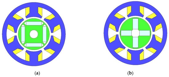
Figure 1.
Cross-sectional view of the 6S4P interior motor (a) standard-type (b) spoke-type.
Table 2 shows the torque characteristics of the standard-type and spoke-type interior motors and a previously studied inset motor [20]. This study found that the average torque of the standard-type and spoke-type interior motors was worse than that of the inset motor, which were 19.5% and 9.24% lower, respectively. Although the inset motor used a larger permanent magnet volume of 69.76 mm3, the torque density of the standard-type and spoke-type interior motors was still lower by 13.7% and 2.6%, respectively.
Table 2.
Characteristics of 6S4P inset, standard-type and spoke-type motor.
2.2.2. Analysis of 9 Slots 6 Poles (9S6P) Interior Motor
The two types of interior motors adopted a 9S6P design to improve torque characteristics. Figure 2 shows a cross-sectional view of the 9S6P standard-type and spoke-type interior motors. The mass and size of the single magnet for both motors were 75 g and 2.5 mm × 0.8 mm × 5 mm, respectively. Table 3 shows the torque characteristics of 9S6P standard-type and spoke-type interior motors. The standard-type interior motor had an average torque of 3.050 mNm, a torque ripple of 66.12%, and the torque was 25.98% higher than the original 4P6S standard-type interior motor. The spoke-type interior motor had an average torque of 3.825 mNm, a torque ripple of 70.27%, and the torque was 40.11% higher than the original 6S4P spoke-type interior motor.
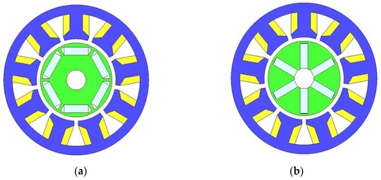
Figure 2.
Cross-sectional view of the 9S6P interior motor (a) standard-type (b) spoke-type.
Table 3.
Characteristics of 9S6P standard-type and spoke-type interior motor.
The overall torque characteristics of the 9S6P interior motors were better than the 6S4P inset motor, with a great improvement in the torque density. The torque of standard-type interior motor was 1.40% higher than the inset motor, the torque ripple was reduced by 11.57%, and the torque density of the permanent magnet was increased by 17.87%. The torque of the spoke-type interior motor was 27.16% higher than the inset motor, the torque ripple was reduced by 6.02%, and the torque density of the permanent magnet was increased by 48.03%. Therefore, this study adopted a 9S6P design and continued with the rotor topology optimization design.
2.3. Optimization Analysis of Interior Rotor
2.3.1. Optimized Design of Standard-Type Rotor
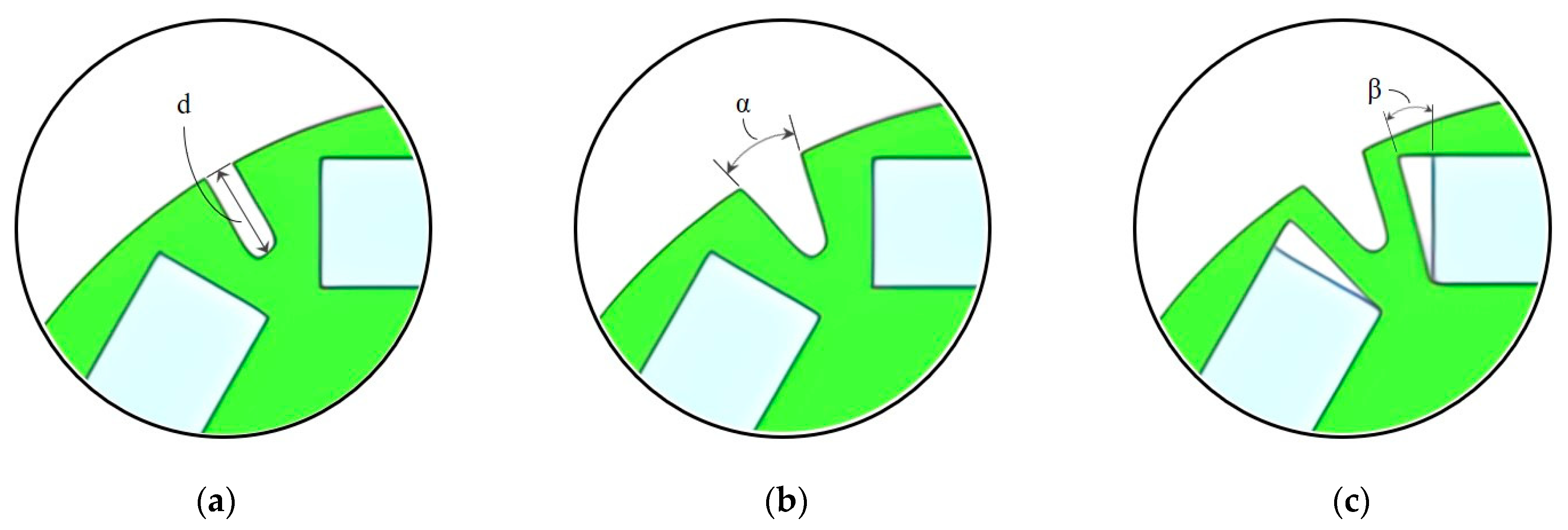
The flux barrier of the standard-type rotor was designed to improve average torque by reducing flux leakage. The rotor structure was based on the single-layer standard-type rotor model of Fang [22] et al. The notch and flux barrier were applied to reduce flux leakage, but carefully selected to avoid any breakage of the rotor structure. The objective function was chosen as the torque density of the permanent magnet in the optimization analysis. Three optimization factors, notch depth (d), notch angle (α), and flux barrier angle (β), were selected as shown in Figure 3. A three-level full factorial experiment was conducted with a total of 27 possible combinations. Table 4 shows the three-factor, three-level full factorial experiment for the standard-type rotor design.
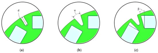
Figure 3.
Three optimization factors for standard-type rotor (a) notch depth (b) notch angle (c) flux barrier angle.
Table 4.
Three-factor, three-level full factorial experiment of standard-type rotor design.
The optimized standard-type rotor design had a notch depth of 0.6 mm, notch angle of 30 degrees and flux barrier angle of 18 degrees. The motor had an average torque of 3.230 mNm and torque ripple of 67.64% as shown in Table 5. Compared with the original model, the torque density of the permanent magnet was increased by 5.90%.
Table 5.
Standard-type interior motor characteristics after optimization.
2.3.2. Optimized Design of Spoke-Type Rotor
To increase the average torque of the spoke-type motor, two rotor parameters, the magnet pole arc and unequal external diameter of rotor (petal-type), were considered as shown in Figure 4. The original rotor design had a magnet pole arc of 60° and external diameter of 7.4 mm. The best parameter design was chosen based on the maximum average torque, but without increasing the torque ripple. The first parameter design was conducted with a magnet pole arc that changed from 52° to 68° in increments of 2°. As shown in Table 6, the average torque and torque ripple both decrease or increase at the same time with variation of the magnet pole arc. Therefore, there was no significant advantage to be gained by changing the magnet pole arc. The magnet pole arc was kept at the original 60°.
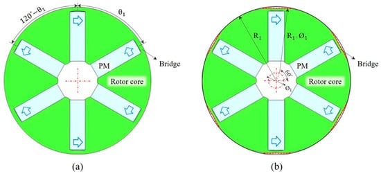
Figure 4.
Two optimization methods for spoke-type rotor (a) magnet pole arc (b) petal-type.
Table 6.
Torque characteristics of magnet pole arc for spoke-type rotor.
The second parameter design was performed with the unequal external diameter changing from 7.4 mm to 6.2 mm in decrements of 0.2 mm. The air gap in the bridge of rotor core was increased to decreased the flux leakage. The torque characteristics of the petal-type design are shown in Table 7. The best design featured a circumscribed circle diameter of 6.2 mm with an average torque of 3.912 mNm and torque ripple of 68.75%. Compared with the original design, the average torque of the petal-type design was increased by 2.27%, and torque ripple was decreased by 2.19%. However, the difference in the average torque was relatively small. Considering the manufacturing difficulty and cost, the external diameter was kept at the original 7.4 mm.
Table 7.
Torque characteristics of petal-type for spoke-type rotor.
The final spoke-type motor used the original rotor design because the two optimization factors, that is, the magnet pole arc and the petal-type improve the torque characteristics of the spoke-type rotor very little and increase the manufacturing difficulty and processing cost. Therefore, these two types of optimized designs were abandoned.
3. Electromagnetic Analysis of Interior Permanent Magnet Synchronous Motor Final Design
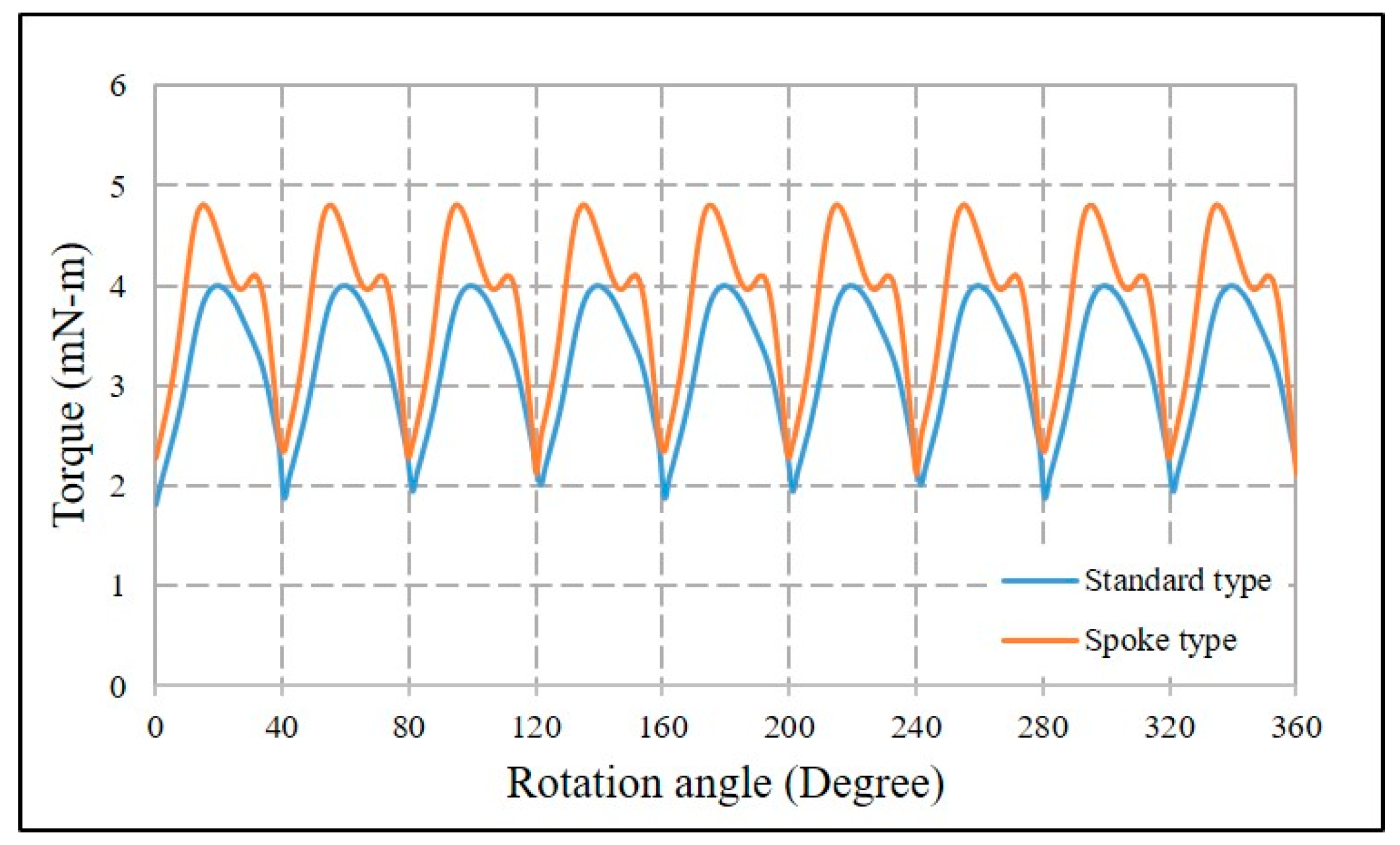
The performances of the 9S6P standard-type and spoke-type interior motors were analyzed and compared. The assembly drawings of the two motors are shown in Figure 5. The average torque was calculated at a single-phase square wave current input of 1 A at rotational speed of 1000 RPM without mechanical load. Figure 6 shows the torque-angle curves of the standard-type and spoke-type interior motors. The standard-type IPMSM had an average torque of 3.230 mNm and torque ripple of 67.64%. The spoke-type IPMSM had an average torque of 3.825 mNm and torque ripple of 70.27%. Figure 7a,b shows the back electromotive force (BEMF)-angle curves of the two motors at the maximum rotational speed of 10,000 RPM. The BEMF of the standard-type and spoke-type interior motors is 4.14 V and 4.68 V, respectively. At the speed of 10,000 RPM, the iron losses of the standard-type and spoke-type interior motors were 0.097 W and 0.134 W. The copper losses of the standard-type and spoke-type interior motors were 0.941 W and 0.569 W.
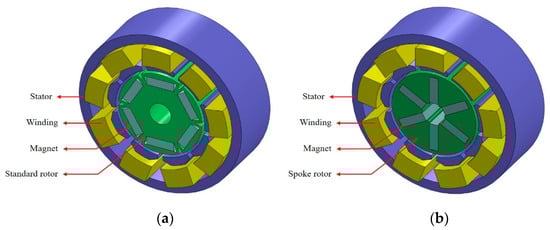
Figure 5.
Assembly drawing of the 9S6P (a) standard-type (b) spoke-type IPMSM.
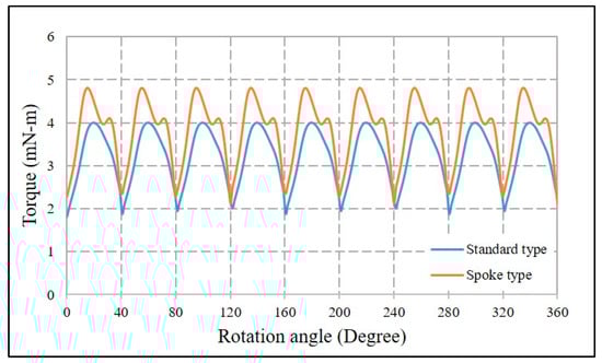
Figure 6.
Torque-angle curves of the 9S6P standard-type and spoke-type interior motors at an input current of 1 A.
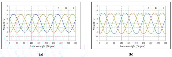
Figure 7.
BEMF-angle curves of the 9S6P (a) standard-type and (b) spoke-type interior motors at a rotational speed of 10,000 RPM.
It was found that the spoke-type IPMSM had a higher air gap flux density with larger average torque and torque ripple. The maximum torque of the standard-type IPMSM occurred at 22 degrees, and the magnetic flux density distribution is shown in Figure 8a. The maximum magnetic flux density was 2.44 T near the notch of the rotor core. The maximum torque of the spoke-type IPMSM occurred at 51 degrees, and the magnetic flux density distribution is shown in Figure 8b. The maximum magnetic flux density was 2.58T in the bridge of rotor core.
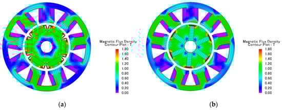
Figure 8.
Magnetic flux density distributions of the 9S6P (a) standard-type and (b) spoke-type interior motors at maximum torques.
Table 8 summarizes the theoretical characteristics of the 6S4P inset motor [20] and the 9S6P standard-type and spoke-type interior motors. This study found that the torque densities of the 9S6P standard-type and spoke-type interior motors were 24.83% and 48.03% higher than those of the 6S4P inset motor, respectively. The average torques of the 9S6P standard-type and spoke-type motor were 7.38% and 27.16% higher than that of the 6S4P inset motor, respectively. The torque ripples of the 9S6P standard-type and spoke-type motor were 9.54% and 6.02% lower than those of the 6S4P inset motor, respectively. The overall performances of the two 9S6P interior motors were better than those of the 6S4P inset motor developed earlier.
Table 8.
Theoretical characteristics of the 6S4P inset motor and the 9S6P standard-type and spoke-type interior motors.
4. Fabrication and Assembly of Interior Permanent Magnet Synchronous Motor
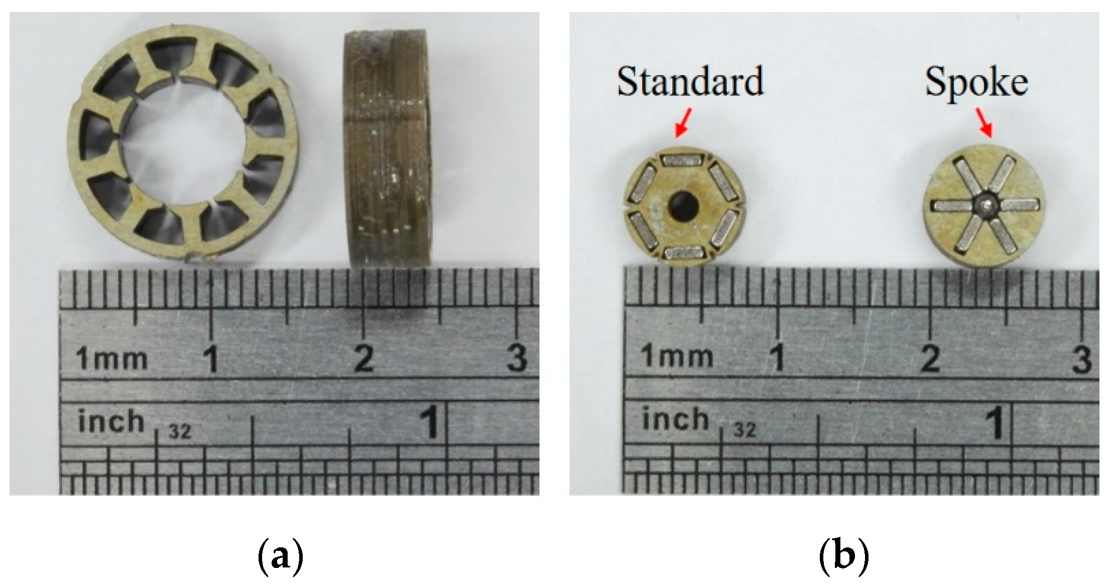
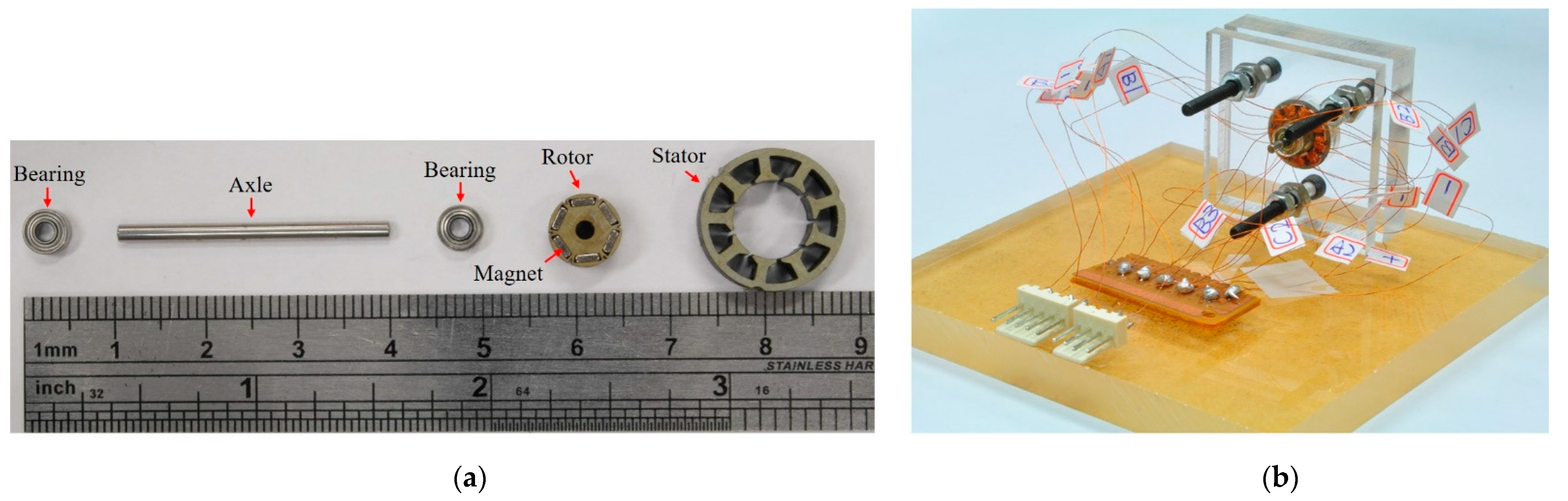
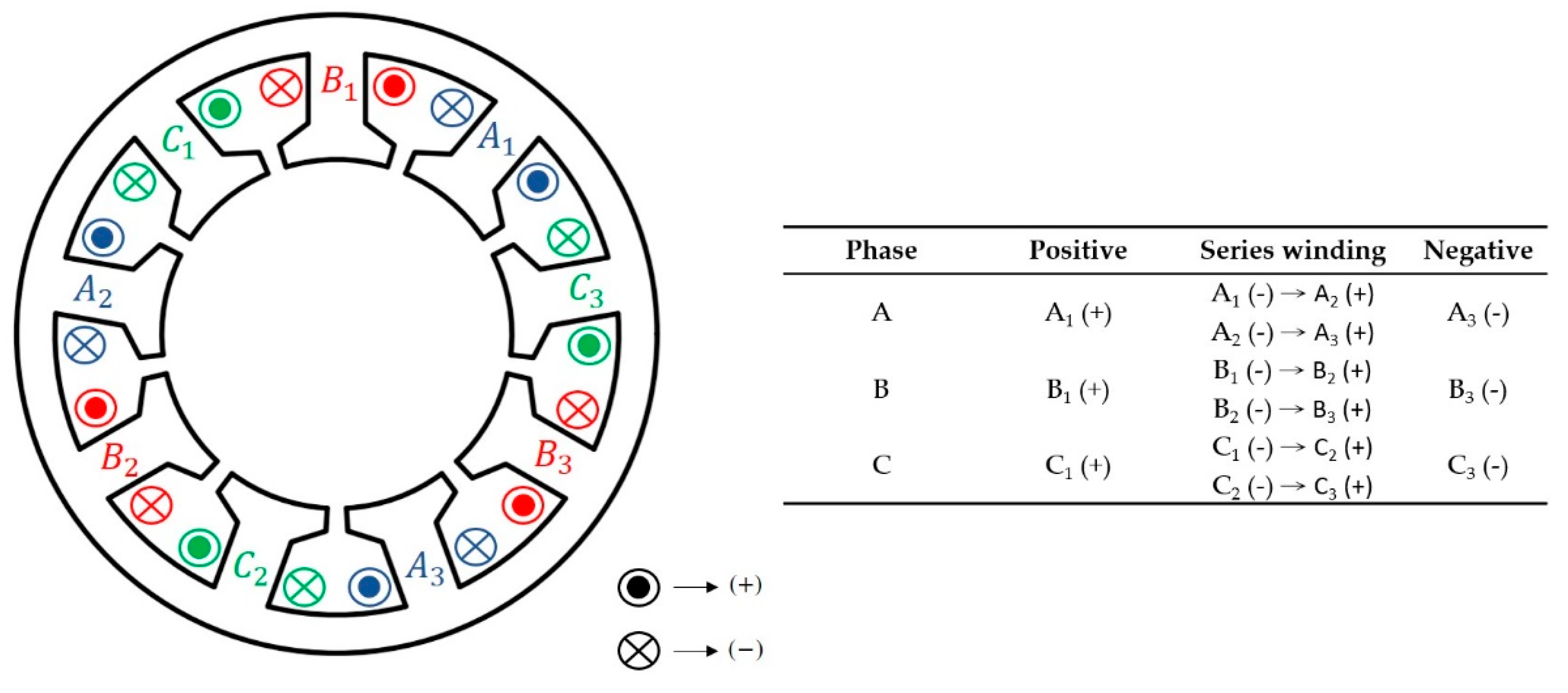
The standard-type and spoke-type interior motors were made of silicon steel sheets (35CS300) and cut by wire electrical discharge machining (WEDM). The stator core and two rotors were stacked and assembled as shown in Figure 9a,b. Photos of the mechanical parts and prototype of the standard-type interior motor are shown in Figure 10a,b. Double-layer fractional slot concentrated winding was adopted for the two interior motors. A schematic of the 3 phase, 9 slots 6 poles stator winding is shown in Figure 11.
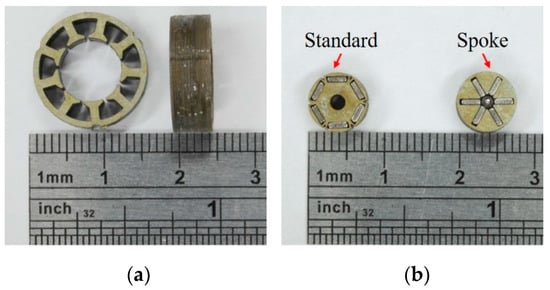
Figure 9.
(a) Stator core (b) standard-type and spoke-type rotors.

Figure 10.
(a) Mechanical parts (b) prototype of the standard-type interior motor.
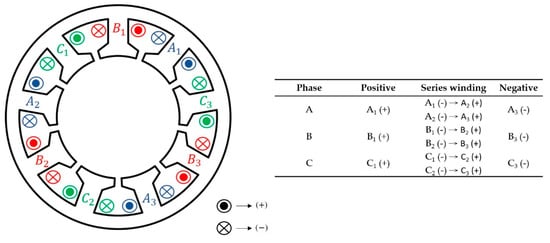
Figure 11.
Schematic of 3 phase, 9-slot 6-pole stator winding.
5. Properties Testing of Interior Permanent Magnet Synchronous Motor
5.1. Motor Testing—Torque
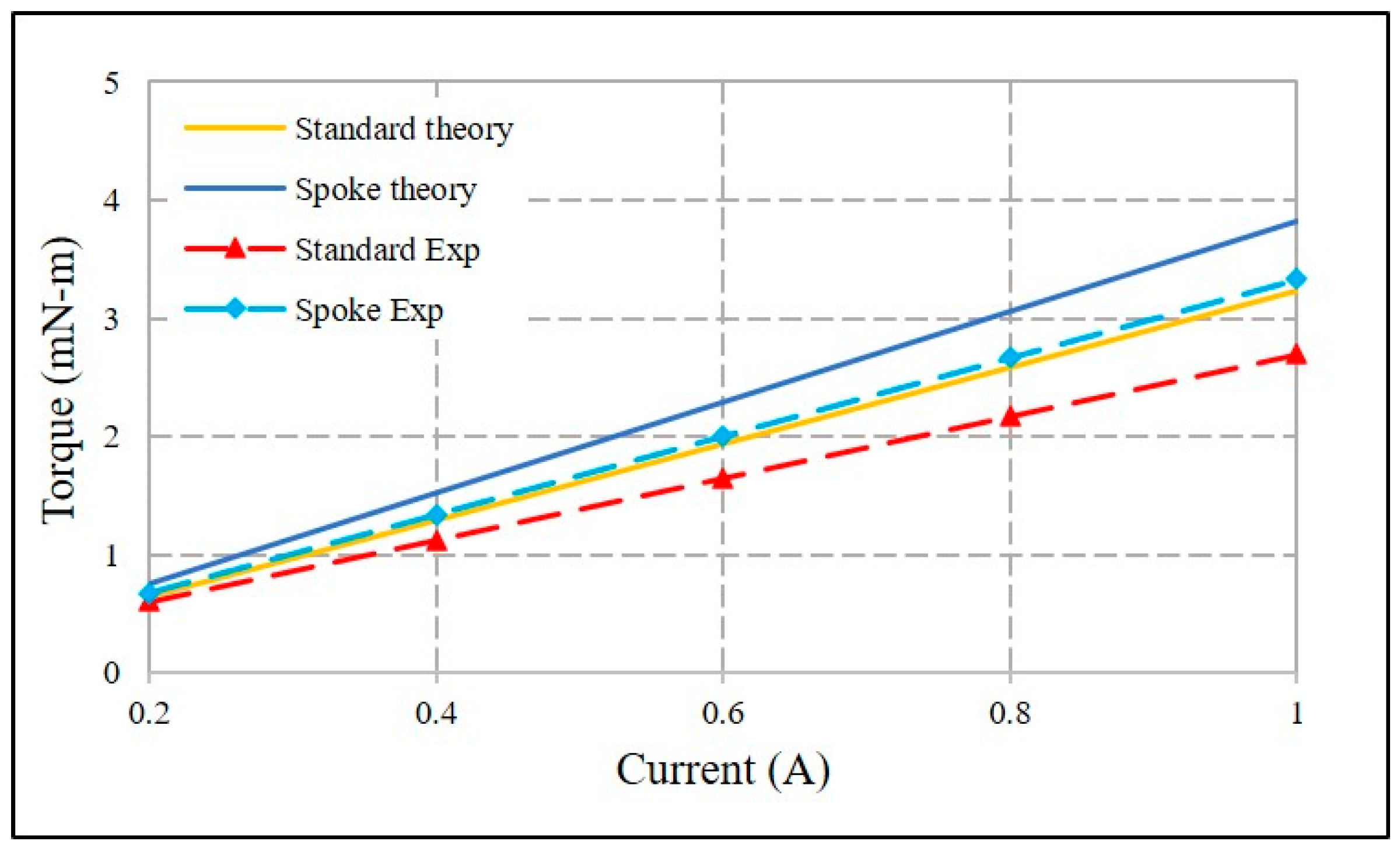
The experimental torque was measured by a micro-dynamometer (HSY. Co., Ltd., Taichung, Taiwan) under different input current conditions. The torque–current curves were tested at currents from 0.2 A to 1 A in an increment of 0.2 A. At a rated current of 1 A, the output torques of the standard-type and spoke-type interior motors were 2.62 mNm and 3.33 mNm, respectively. The torque constants (KT) of the standard-type and spoke-type interior motors were 2.80 mNm/A and 3.35 mNm/A, respectively. The theoretical and experimental KT of the two interior motors are compared in Table 9 and torque–current curves are plotted as shown in Figure 12. The errors between the theoretical and experimental KT of the standard-type and spoke-type interior motors was −13.0% and −12.5%, respectively. The experimental KT of the standard-type motor was 19.6% less than that of the spoke-type motor.
Table 9.
Comparison of torque constants (KT) of standard-type and spoke-type interior motors.
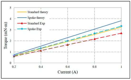
Figure 12.
Torque–current curves of standard-type and spoke-type interior motors.
5.2. Motor Testing—Back Electromotive Force (BEMF)
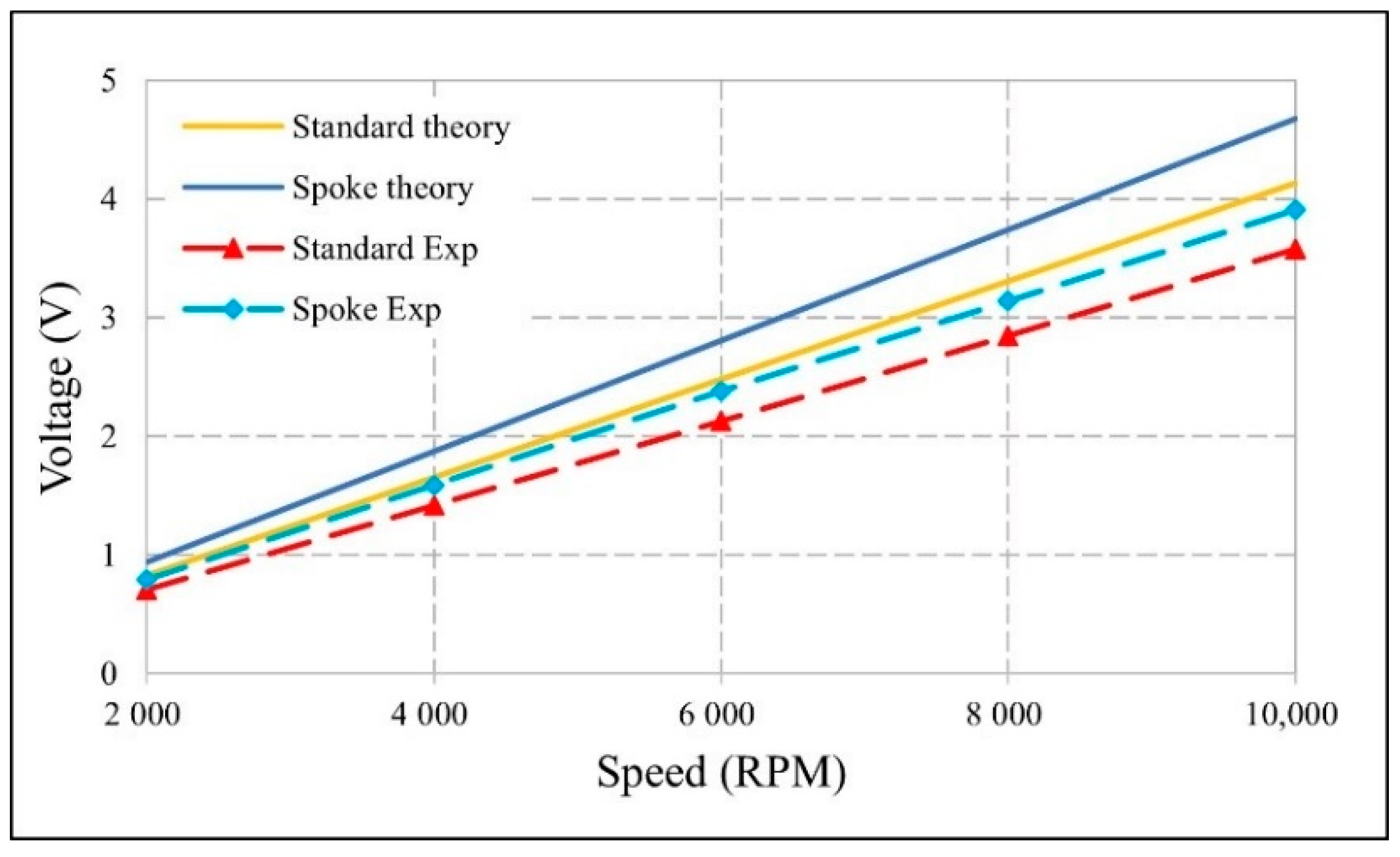
The experimental BEMF was measured using a brushless DC motor (Faulhaber-2036U012B) with a coupler to drive the interior motors at 2000 RPM interval from 2000 to 10,000 RPM. At a rotational speed of 10,000 RPM, the BEMF for the standard-type and spoke-type interior motors was 3.58V and 3.91 V, respectively. The BEMF constants (KE) of the standard-type and spoke-type interior motors were 3.40 mV/(rad/s) and 3.77 mV/(rad/s), respectively. The theoretical and experimental KE of the two interior motors is compared in Table 10 and the voltage–speed curves are plotted as shown in Figure 13. The error between the theoretical and experimental KE of the standard-type and spoke-type interior motors was −13.9% and −15.7%, respectively. The experimental KE of the standard-type interior motor was 10.9% less than that of the spoke-type interior motor.
Table 10.
Comparison of BEMF constants (KE) of standard-type and spoke-type interior motors.
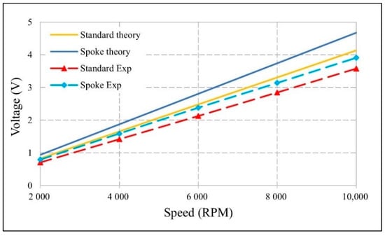
Figure 13.
Voltage–speed curves of standard-type and spoke-type interior motors.
6. Conclusions
This paper demonstrated the feasibility of the industrial application of the micro interior motor, as it achieved a similar performance to that of other permanent magnet synchronous motors. Two micro interior permanent magnet synchronous motors, standard-type and spoke-type, were developed with an external diameter of 15 mm, a rotor external diameter of 7.5 mm, and a length of 5 mm. To exceed the torque density of an inset motor of the same size, the slot pole number of the interior motor was increased from 6 slots 4 poles to 9 slots 6 poles. The permanent magnet shape and rotor topology of two motors were also redesigned to achieve a higher output torque and smaller permanent magnet volume. The spoke-type IPMSM had a higher output torque, while the standard-type IPMSM had a lower torque ripple. At an input square wave current of 1 A, the two motors achieved a torque over 2.62 mNm and a maximum speed of 10,000 RPM. Both motors could match the performance of a commercial BLDC motor such as Faulhaber 1509T006B. The micro interior motors are suitable for low-power, variable-speed applications, such as small aircraft, hand-held power tools and micro robots. However, it must be noted that the increase in the slot pole number will increase the number of parts and shrink their size, resulting in difficulties in their micro fabrication and assembly.
Author Contributions
Conceptualization, D.-C.P.; methodology, D.-C.P.; validation, D.-C.P., Z.-J.S., Y.-H.C., H.-C.H., and G.-T.B.; formal analysis, D.-C.P., Z.-J.S., Y.-H.C. and G.-T.B.; investigation, D.-C.P., Z.-J.S., Y.-H.C., H.-C.H., and G.-T.B.; data curation, D.-C.P., Z.-J.S., Y.-H.C.; writing—original draft preparation, D.-C.P., Z.-J.S., Y.-H.C.; writing—review and editing, D.-C.P., H.-C.H. and G.-T.B.; supervision, D.-C.P. All authors have read and agreed to the published version of the manuscript.
Funding
This work was partially funded by the MEMS and Precision Machinery Research and Development Center and the Department of Mechanical Engineering at National Kaohsiung University of Science and Technology.
Conflicts of Interest
The authors declare no conflict of interest.
References
- Rahideh, A.; Korakianitis, T. Analytical Magnetic Field Distribution of Slotless Brushless Machines with Inset Permanent Magnets. IEEE Trans. Magn. 2011, 47, 1763–1774. [Google Scholar] [CrossRef]
- Steen, C.R. Direct Axis Aiding Permanent Magnets for a Laminated Synchronous Motor Rotor. U.S. Patent 4139790A, 13 February 1979. Available online: https://patentimages.storage.googleapis.com/39/e3/99/469e70252be590/US4139790.pdf (accessed on 1 July 2021).
- Rahman, M.A. History of interior permanent magnet motors [History]. IEEE Ind. Appl. Mag. 2013, 19, 10–15. [Google Scholar] [CrossRef]
- Soong, W.L.; Ertugrul, N. Field-weakening performance of interior permanent-magnet motors. IEEE Trans. Ind. Appl. 2002, 38, 1251–1258. [Google Scholar] [CrossRef] [Green Version]
- Pellegrino, G.; Vagati, A.; Guglielmi, P.; Boazzo, B. Performance Comparison Between Surface-Mounted and Interior PM Motor Drives for Electric Vehicle Application. IEEE Trans. Ind. Electron. 2012, 59, 803–811. [Google Scholar] [CrossRef] [Green Version]
- Kim, S.; Kim, Y.; Lee, G.; Hong, J. A Novel Rotor Configuration and Experimental Verification of Interior PM Synchronous Motor for High-Speed Applications. IEEE Trans. Magn. 2012, 48, 843–846. [Google Scholar] [CrossRef]
- Chiu, M.; Chiang, J.; Lin, C. Design and Optimization of a Novel V-Type Consequent-Pole Interior Permanent Magnet Synchronous Motor for Applying to Refrigerant Compressor. In Proceedings of the 2018 21st International Conference on Electrical Machines and Systems (ICEMS), Jeju, Korea, 7–10 October 2018; pp. 413–418. [Google Scholar]
- Electric Traction Motors for EVs See 17.4% CAGR Over Next Decade. Available online: https://www.electricvehiclesresearch.com/articles/5497/electric-tractioN·motors-for-evs-see-17-4-cagr-over-next-decade (accessed on 14 April 2021).
- Wang, A.; Jia, Y.; Soong, W.L. Comparison of Five Topologies for an Interior Permanent-Magnet Machine for a Hybrid Electric Vehicle. IEEE Trans. Magn. 2011, 47, 3606–3609. [Google Scholar] [CrossRef]
- Rahman, M.M.; Kim, K.; Hur, J. Design and Analysis of Neodymium Free SPOKE-Type Motor with Segmented Wing Shape Permanent-Magnet for Concentrating Flux Density. In Proceedings of the 2013 IEEE Energy Conversion Congress and Exposition (ECCE), Denver, CO, USA, 15–19 September 2013; pp. 4991–4997. [Google Scholar]
- Yu, D.; Huang, X.Y.; Fang, Y.T.; Zhang, J. Design and Comparison of Interior Permanent Magnet Synchronous Traction Motors for High Speed Railway Applications. In Proceedings of the 2017 IEEE Workshop on Electrical Machines Design, Control and Diagnosis (WEMDCD), Nottingham, UK, 20–21 April 2017; pp. 58–62. [Google Scholar]
- Kim, M.; Cho, S.; Lee, K.; Lee, J.; Han, J.; Jeong, T.; Kim, W.; Koo, D.; Lee, J. Torque Density Elevation in Concentrated Winding Interior PM Synchronous Motor with Minimized Magnet Volume. IEEE Trans. Magn. 2013, 49, 3334–3337. [Google Scholar] [CrossRef]
- Morimoto, S. Trend of permanent magnet synchronous machines. IEEJ Trans. Electr. Electron. Eng. 2007, 2, 101–108. [Google Scholar] [CrossRef]
- Fang, L.; Kim, S.; Kwon, S.; Hong, J. Novel Double-Barrier Rotor Designs in Interior-PM Motor for Reducing Torque Pulsation. IEEE Trans. Magn. 2010, 46, 2183–2186. [Google Scholar] [CrossRef]
- Lee, S.; Kang, G.; Hur, J.; Kim, B. Stator and Rotor Shape Designs of Interior Permanent Magnet Type Brushless DC Motor for Reducing Torque Fluctuation. IEEE Trans. Magn. 2012, 48, 4662–4665. [Google Scholar] [CrossRef]
- Kim, K. A Novel Method for Minimization of Cogging Torque and Torque Ripple for Interior Permanent Magnet Synchronous Motor. IEEE Trans. Magn. 2014, 50, 793–796. [Google Scholar] [CrossRef]
- Upadhyay, P.; Rajagopal, K.R. Torque Ripple Minimization of Interior Permanent Magnet Brushless DC Motor Using Rotor Pole Shaping. In Proceedings of the 2006 International Conference on Power Electronic, Drives and Energy Systems, New Delhi, India, 12–15 December 2006; pp. 1–3. [Google Scholar]
- Xiao, Y.; Zhu, Z.Q.; Chen, J.T.; Wu, D.; Gong, L.M. A Novel Spoke-type Asymmetric Rotor Interior PM Machine. In Proceedings of the 2020 IEEE Energy Conversion Congress and Exposition (ECCE), Drives and Energy Systems, Detroit, MI, USA, 11–15 October 2020; pp. 4050–4057. [Google Scholar]
- Park, M.; Kim, D.; Jung, J.; Hong, J. Design of high torque density multi-core concentrated flux-type synchronous motors considering vibration characteristic. IEEE Trans. Ind. Appl. 2017, 55, 1351–1359. [Google Scholar] [CrossRef]
- Pang, D.C.; Shi, Z.J.; Xie, P.X.; Huang, H.C.; Bui, G.T. Investigation of an Inset Micro Permanent Magnet Synchronous Motor Using Soft Magnetic Composite Material. Energies 2020, 13, 4445. [Google Scholar] [CrossRef]
- Lee, S.G.; Bae, J.; Kim, W. Study on the Axial Leakage Magnetic Flux in a Spoke Type Permanent Magnet Synchronous Motor. IEEE Trans. Magn. 2019, 55, 5881–5887. [Google Scholar] [CrossRef]
- Fang, L.; Jung, J.; Hong, J.; Lee, J. Study on High-Efficiency Performance in Interior Permanent-Magnet Synchronous Motor with Double-Layer PM Design. IEEE Trans. Magn. 2008, 44, 4393–4396. [Google Scholar] [CrossRef]


Publisher’s Note: MDPI stays neutral with regard to jurisdictional claims in published maps and institutional affiliations. |
© 2021 by the authors. Licensee MDPI, Basel, Switzerland. This article is an open access article distributed under the terms and conditions of the Creative Commons Attribution (CC BY) license (https://creativecommons.org/licenses/by/4.0/).