Abstract
The paper presents the results of laboratory tests and FEM 2D calculations of the DCEFSM (Direct Current Excited Flux Switching Machine) electric motor prototype, made based on the stator ferromagnetic sheets of the induction motor. Static measurements of torques, currents, power, efficiency, electromotive forces, and voltages of the motor under various operating conditions were performed, as well as the recordings of its currents and back-EMFs waveforms. FEM calculations of measured values were also performed. The obtained results allow us to conclude that the motor has the operating properties of an under-excited synchronous cylindrical motor and can be vector controlled like the PMSM motor. The results of measurements and calculations indicate the need to redesign the magnetic circuit of the stator.
1. Introduction
Electric motors without permanent magnets can be chronologically divided into two groups: motors known for several decades, such as rotating magnetic field motors (induction motors—IM and electromagnetically excited synchronous motors—SM) and commutator motors (DC and AC), and motors constructed or improved during the last 20 years, based on the growing computational capabilities (FEM) and technological possibilities of producing magnetic circuits of electric machines. They must compete with both the motors of the first group, often significantly improved concerning their predecessors (SyRM—Synchronous Reluctance Motor, SRM—Switched Reluctance Motor), and with motors with neodymium permanent magnets (PMSM—Permanent Magnet Synchronous Motor, IPMSM—Internal Permanent Magnet Synchronous Motor, HEFSM—Hybrid Excitation Flux Switching Machine). The reason for the development of this new group of motors is the possibility of obtaining unit torques and power not less than in motors excited by magnets while maintaining their high efficiency. The elimination of magnets is advantageous in terms of price, technology, and operation, due to the limited operating temperatures of the magnets and their susceptibility to rust. There is also the possibility of limiting the weight of copper needed to make the winding, by replacing conventional distributed windings (as in rotating field machines) with windings composed of concentrated coils, i.e., with a pitch of (as in SRM).
In 2010, at a conference in Lille, France (Vehicle Power and Propulsion Conference, 1–3 September), and in 2011, at a conference in Birmingham, UK (14th European Conference on Power Electronics and Applications, 30 August–1 September), two different teams proposed a way to replace permanent magnets with DC coils for three-phase flux switching motors (HEFSMs) [1,2]. These machines were based on the multiplication of the configuration of the field and armature windings used in a single-phase AC motor with flux switching [3]. This relatively new machine is known by the acronym DCEFSM—Direct Current ExcitedFlux Switching Machine (acronyms: FEFSM—Field-Excited Flux Switching Machine—and WFFSM—Wound-Field Flux Switching Machine—are also used). In 2013–2017, the team from the University of Eindhoven has published the results of its research on the operating principle of the DCEFSM [4] and optimization of its design [5,6,7,8,9,10,11,12,13,14], particularly for use in electric vehicles. The research was initially carried out for the motor version with stator teeth and rotor teeth. These studies led to a change in the topology of the motor’s magnetic circuit to increase the torque and reduce its alternating components. The topology ( stator teeth and rotor teeth) of the three-phase motor has become the subject of computational studies (by FEM) [6,10,11]. The studies showed the potential competitiveness of machines with this topology concerning rotary field machines excited by magnets, both due to comparable values of the unit torque and due to comparable possibilities of control of the speed of the motor.
In [15] the topology of the magnetic circuit of the machine was proposed, i.e., twice the topology . Using FEM calculations, the design of a three-phase motor with this topology was optimized and a prototype was built. The results of the prototype measurements showed a unit power of up to (with an efficiency of up to ), which is a value higher than that obtained in typical IPMSM, SRM, and IM motors. In an earlier paper [16], two DCEFSM motor topologies— and —were compared (by FEM calculations), obtaining similar torques and back-EMF. The coil arrangement has been examined to validate each armature coil chase and to prove the operating principle of the machine. The results were used by the Authors to choose the topology for further research, as it was simpler and resulted in a lower frequency of armature currents.
The data included in [15] made it possible to perform our control calculations. They were performed as static 2D FEM calculations using the FEMM program [17]. The results confirmed the results presented in [18], but for a slot filling factor by a copper equal and a current density of , which would practically require cooling the motor with water.
The reason for the research on the design of DCEFSM motors was the confirmation by the results of own calculations of the DCEFSM motor with the topology of its competitiveness (regarding torque and power) against the motors with similar dimensions: HEFSM [19], HEMFM (Hybrid Excited Modulated Flux Machine) [20], DCEMFM (DC Excited Modulated Flux Machine) [21], and IM. In the FEM calculations presented in [18], the outer dimensions of the stator were assumed as in a three-phase, squirrel-cage IM motor with a rated power of and a synchronous speed of (at power supply). Simulation tests (FEM) also showed that the DCEFSM machine should have the operating properties of a cylindrical synchronous machine with electromagnetic excitation. These favorable results were the starting point for the design of a larger three-phase motor with a topology to be powered by a frequency inverter that controls this motor like PMSM. The prototype of this motor became the subject of research, the results of which are presented in this paper.
The research aimed to verify the analytical and numerical (FEM 2D) calculations of the design of the DCEFSM motor—with 36 stator slots and 15 rotor teeth—and also its operating properties. The obtained measurement results were used to further optimize the motor design.
The Authors of [10,13,15,22,23] believe that the main application of the new motors is in electric vehicles. Based on the presented measurement results, it can be concluded that such motors can be competitive for induction and synchronous motors in all applications, at lower current densities than those used in motors designed for electric cars, i.e., without water cooling of the armature.
2. Materials and Methods
2.1. Machine and It’s Operation
The cross-section of the motor is shown in Figure 1. The stator outer diameter is , the rotor diameter—, the air gap has a minimum radial dimension of . The length of the stator and rotor sheet package is . The external dimensions of the stator sheet package correspond to an induction motor with a rated power of approx. and a synchronous speed of (). These sheets are from a typical induction motor. The machine has slots on the stator and teeth of the rotor. Both the field winding and the three-phase armature have a pitch . The field winding and the armature winding are double-layer. The number of pairs of the armature phase poles is , and the number of pairs of the field winding is . The armature phase coils do not overlap, but they partially overlap with the coils of the field winding. The armature winding is wye connected, phase coils are connected in series. The coils of the field winding are also connected in series. The motor is designed to work in a speed control system, powered by sinusoidal three-phase voltages, formed as a function of the measured rotor position. It is a control system analogous to the PMSM vector control (Field Oriented Control—FOC) of speed. The use of such a system results from the operating properties analogous to those of a cylindrical synchronous motor—the motor can be identified as a cage-less, synchronous cylindrical machine. The rated motor speed of is achieved with a supply voltage frequency of . The photo of the motor on the test bench is shown in Figure 2. Rated motor parameters (obtained from measurements) are presented in Table 1.
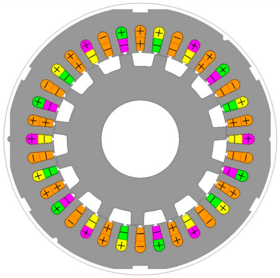
Figure 1.
Cross-section of the motor from the model for FEM calculations. Orange color—field winding (for DC current); yellow, green, purple—phase windings (for AC currents); gray—ferromagnetic sheet.
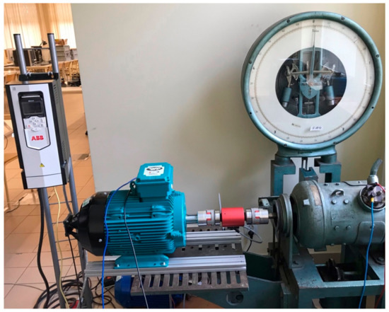
Figure 2.
The tested motor (blue) with encoder on a test bench. In the upper left corner of the photo, there is an inverter that powers the motor. On the right is a loading DC generator and between machines is a torque meter (red).

Table 1.
Rated motor parameters.
In this motor the field coils overlap the armature coils. It is necessary for the change in the direction of the flux associated with the phases of the armature, coming from the field winding. The change of direction of this flux occurs during the movement of the toothed rotor. The rotor speed and number of rotor teeth determine the back-EMF pulsation. When a direct current flows in the field winding and the rotor rotates at a constant angular speed, the period of the back-EMF is one rotation of the rotor divided by , so the pulsation of the back-EMF is . The dependence of the period of the back-EMF on the number of rotates per minute n can be expressed by the formula:
To obtain a non-zero mean value of the motor torque, the pulsation of the three-phase armature currents should also be equal to . The armature winding has pairs of poles, so the speed of the rotating field produced by armature winding is:
For the tested motor this is . The rotor rotates in relation to the rotating field from armature with a slip:
For the tested motor this is Thus there is no synchronism between the rotating armature magnetic field and the rotating rotor.
Generally, this motor is not a rotating field machine, as induction or synchronous machine, despite the sinusoidal voltages and currents. The rotating field of the armature exists but is not used for the torque generation.
2.2. Test Bench and Test Scenarios
The scheme of the measurement system is shown in Figure 3. The motor was powered by an inverter with PWM modulation of output voltages, with a frequency of . The inverter controlled the motor as a PMSM motor. The inverter recognized and identified it. The currents, voltages, and electric power of the armature were measured with Hall effect voltage transducers measuring the phase voltages , and Hall effect current transducers measuring the currents of the supply lines , , . The output signals of the voltage and current transducers were sampled at a frequency of for each channel. Based on these measurements, the active power of armature was computed in real-time, as in (4). For checking, this power was measured with two electrodynamic wattmeters in the Aron circuit, connected directly to the supply lines. The field winding DC voltage and current, coming from a stabilized, separated, laboratory DC Power Supply, were measured directly with a digital laboratory voltmeter and a magnetoelectric ammeter. The torque on the shaft was measured directly with a precise DATAFLEX 32/100 (KTR Systems GmbH, Carl-Zeiss-Straße 25, 48432 Rheine, Germany) torque meter with a measurement error lower than . The steady-state motor speed was measured with a strobe tachometer, measuring the rotation speed with an accuracy of digits. In steady states of the motor, its rotation speed is unambiguously determined by the frequency of voltages and currents supplying the armature, which was also measured based on signals from current transducers. The motor was loaded by a separately excited DC generator with adjustable excitation and variable armature load resistance. The temperature of the motor windings was measured indirectly—after each series of measurements, the armature phase resistances and the field winding resistance were measured by the Voltmeter-Ammeter method. The comparison of these resistances with the resistances measured in the cold state made it possible to determine the average temperature rise for the entire windings.
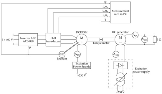
Figure 3.
Simplified schematic diagram of the motor measuring system.
Identification measurements of the motor and measurement of its operating characteristics and properties were carried out. Identification measurements included:
- Measurement of the resistance of the machine windings in the cold and hot state. Measurements were made using Voltmeter-Ammeter DC method with accurate voltage measurement;
- Measurement of self- and mutual inductances of armature phases as a function of rotor position. Measurements were made using an ammeter AC, two voltmeters AC and wattmeter, with accurate voltage measurement, supplying one phase of the armature with sinusoidal voltage. The measuring current was sinusoidal and its RMS value was . Therefore the measurement was performed with the machine’s magnetic circuit unsaturated;
- Measurement of armature inductances and as for a synchronous machine. Measurements were made using an ammeter AC, voltmeter AC, and wattmeter, with accurate voltage measurement, supplying two phases of the armature (connected in wye) with sinusoidal voltage, with two rotor positions: corresponding to the maximum measured inductance (as ) and it’s minimum (as ). The measuring current was sinusoidal and its RMS value was ;
- Measurement of a field winding inductance as a function of rotor position and mutual inductance between field winding and one armature phase. Measurements were made using an ammeter AC, two voltmeters AC, and wattmeter, with accurate voltage measurement, supplying the field winding with sinusoidal voltage. The measuring current was sinusoidal and its RMS value was ;
- Recordings of phase and phase-to-phase EMF waveforms induced in the armature, as a function of the field current (DC), when driving the motor with a constant speed (as an idling generator).
Measurements of the operating characteristics and properties included:
- Measurement of the RMS values of the armature currents as a function of the load torque, at different field currents and different rotation speeds of the motor;
- Measurement of the motor efficiency as a function of the load torque, at different field currents and different motor rotation speeds;
- Measurement of the angular characteristic of the motor starting torque;
- Recordings of phase waveforms of motor voltages and currents when the motor is powered by the inverter.
3. Results
The results of the motor identification measurements are presented in Table 2, Table 3 and Table 4 and Figure 4, Figure 5, Figure 6, Figure 7, Figure 8 and Figure 9. The tables contain the results of measurements of the windings resistances and their maximum and minimum inductances. These inductances with the rotor position vary practically sinusoidally, from the minimum value to the maximum value from Table 3—Figure 4 and Figure 5. The exception is the mutual inductance between field winding and the armature phase—Figure 6. For this reason, the rotational EMF is not exactly sinusoidal, but its THD coefficient is only (up to the 40th harmonic), and the highest value of the higher harmonic (7th) is of the first harmonic—Figure 7 and Figure 8. The results of the identification measurements show that the machine can be identified as a cylindrical synchronous machine, rated under-excited.
Table 2.
The results of measurements of the windings resistances.
Table 3.
The results of measurements and FEM calculations of the windings inductances.
Table 4.
The results of measurements and FEM calculations of the synchronous inductances.
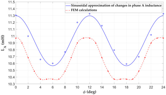
Figure 4.
Measured and calculated inductance of armature phase A, as a function of the rotor position angle.
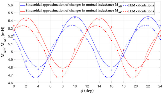
Figure 5.
Measured and calculated mutual inductances between armature phases, as a function of the rotor position angle.
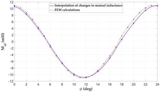
Figure 6.
Measured and calculated mutual inductance between the armature phase A and the field winding, as a function of the rotor position angle.
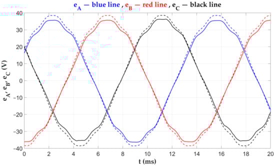
Figure 7.
Measured (solid line) and calculated (dashed line) phase EMF waveforms of the armature at the generator operation of the machine with an open armature winding, speed , and field current .
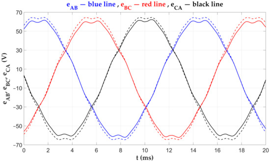
Figure 8.
Measured (solid line) and calculated (dashed line) phase-to-phase EMF waveforms of the armature at the generator operation of the machine with an open armature winding, speed , and field current .
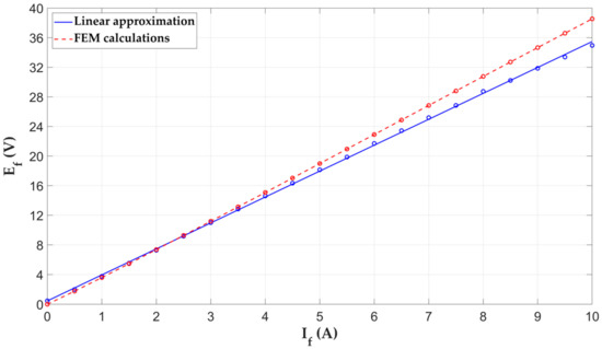
Figure 9.
Measured (blue) and calculated (red) RMS value of the EMF in phase A of the armature, as a function of the field current, at the generator idle state, at the speed .
The results of operating characteristics measurements are shown in Figure 10, Figure 11, Figure 12, Figure 13, Figure 14, Figure 15, Figure 16, Figure 17, Figure 18 and Figure 19. The aim of the measurements was:
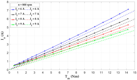
Figure 10.
Measured (solid line) and calculated (dashed line) dependence of the RMS current of the armature phase on the load torque of the motor for different values of the field current, at the rotor speed .
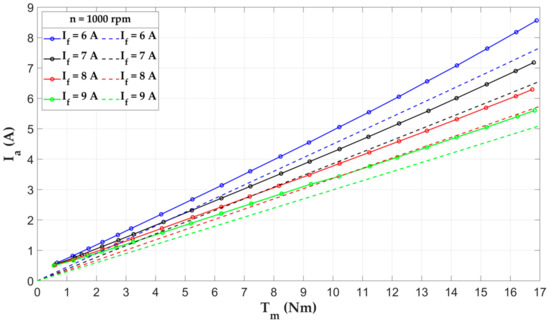
Figure 11.
Measured (solid line) and calculated (dashed line) dependence of the RMS current of the armature phase on the load torque of the motor for different values of the field current, at the rotor speed .
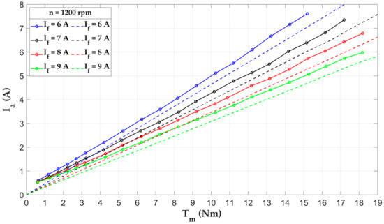
Figure 12.
Measured (solid line) and calculated (dashed line) dependence of the RMS current of the armature phase on the load torque of the motor for different values of the field current, at the rotor speed .
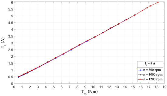
Figure 13.
The measuring dependence of the RMS armature phase current on the motor load torque for different rotor speeds and the field current .
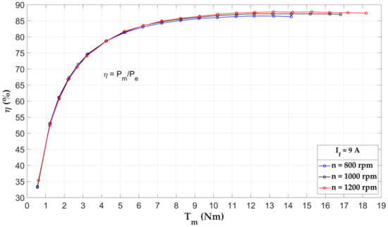
Figure 14.
Measured motor efficiency without power losses in the field winding as a function of motor load torque, at field current and different rotor speeds.
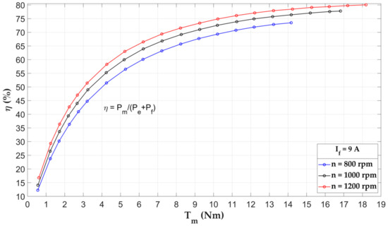
Figure 15.
Measured motor efficiency with power losses in the field winding as a function of motor load torque, at field current and different rotor speeds.
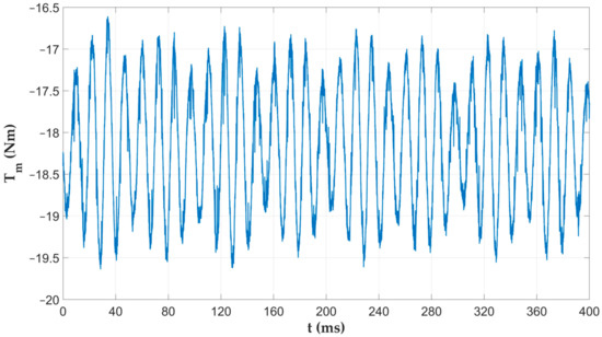
Figure 16.
Recording of motor torque waveform, at field current and rotor speed ; load torque is .
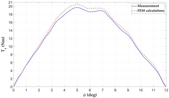
Figure 17.
Measured and calculated dependence of the motor starting torque on the rotor position angle, at the field current and the DC current of two armature phases (current flows into the first phase, it flows out from the second phase, and the current for the third phase is , the rotor is stopped).
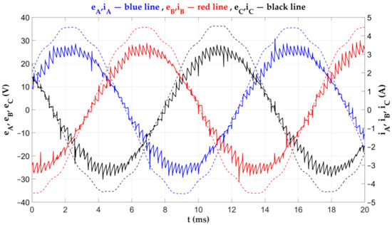
Figure 18.
Waveforms of phase currents (solid line) and phase EMFs (dashed line) of the motor, obtained post factum by superposition the recorded angular waveforms of the EMFs (generator idling) and recorded angular waveforms of the currents (motor powered by the inverter).
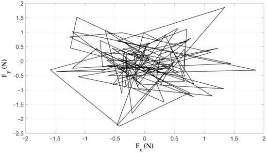
Figure 19.
Horizontal () and vertical () components of the force acting on the rotor, for various rotor positions, changed within one rotor tooth pitch ()—results of FEM calculations.
- Confirmation of the thesis about the functioning of the motor as a cylindrical, under-excited, synchronous motor;
- Measurement of the alternating component of the motor torque (Figure 16);
- Confirmation of the motor’s ability to generate starting torque (Figure 17);
- Confirmation of the correctness of the vector control (FOC) of the motor by the inverter as a PMSM motor (Figure 18).
The efficiency of the motor (Figure 14 and Figure 15) was measured in steady states as:
where: , —average value of the torque measured by the torque meter on the shaft, —rotor speed measured by a strobe meter, —power losses in field winding: , —DC voltage of the field winding (from laboratory Power Supply) measured by a digital voltmeter, —DC current of the field winding, measured by a magnetoelectric ammeter, —power of the armature, calculated on the basis of registered voltages and current waveforms of the armature of the motor, —the period of the armature voltage and current waveforms, —time.
The sound level measured at the side of the motor, at a distance of m, at the height of the shaft, with a torque load of , is , so it exceeds the values for induction motors. However, this level is lower than for other motors with large rotor teeth, such as the SRM. The sound level was measured using the FLUS ET-965 (Shenzhen Flus Technology Co., Ltd., 3rd Floor, Lantian Building, Fountian Science Park, Pingan Road, Pinghu Town, Longgang District, Shenzhen, China 518111) digital multifunctional environmental meter. The decibel meter works in the range with the measurement accuracy and the sensitivity .
The computational (FEM) dependence of the radial forces acting on the rotor on the rotor position angle is shown in Figure 19. These forces do not exceed , so they do not exceed the values of radial forces in induction motors of such power.
Figure 20 and Figure 21 show the computational (FEM) magnetic flux density distribution in the machine air gap in the idle operation (,, ) and with rated armature current (,, ). Figure 20 shows the normal component of the magnetic flux density, and Figure 21 shows the magnetic flux density module. Under load occurs a change in the direction of magnetic flux density under some of the stator and rotor teeth. There is also a big increase in the magnetic flux density under some of the stator teeth. This results in the saturation of these teeth.
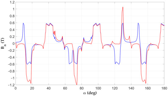
Figure 20.
Normal component of the magnetic flux density distribution in the machine air gap (for of the magnetic circuit) in the idle operation (,—blue line) and with rated armature current (,—red line)—results of FEM calculations.
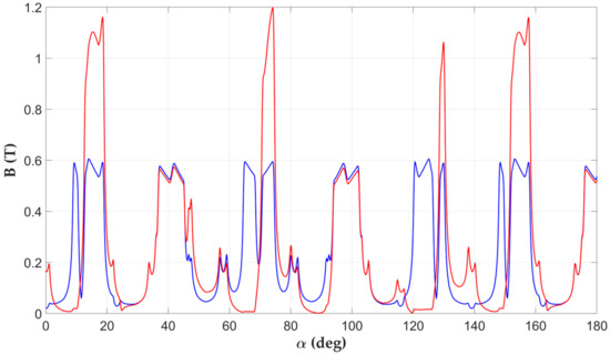
Figure 21.
Magnetic flux density distribution in the machine air gap (for of the magnetic circuit) in the idle operation (,—blue line) and with rated armature current (,—red line)—results of FEM calculations.
Figure 22 shows the magnetic field lines and the values of the magnetic flux density in the cross-section of the machine in the idling state (). The relatively low level of magnetic flux density is noteworthy, both in the stator teeth and in its yoke. Its values do not exceed (in some stator teeth only). This explains the linear increase in EMF of the machine with the field current, in its idle state, shown in Figure 9. The appearance of the rated armature current (Figure 23) significantly increases the saturation, but in the stator teeth only. However, this does not disturb the linear increase in motor torque with the RMS value of the armature current. On the other hand, this results in the lack of an increase in the value of the excitation magnetic flux with an increase in the field current over .
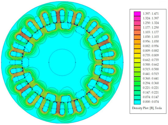
Figure 22.
The magnetic field lines and the values of the magnetic flux density in the cross-section of the machine in the idle operation (,)—results of FEM calculations.
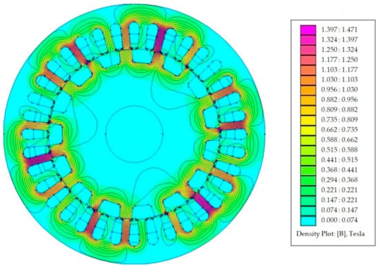
Figure 23.
The magnetic field lines and the values of the magnetic flux density in the cross-section of the machine with rated armature current (, )—results of FEM calculations.
4. Discussion
The test results confirmed the thesis that the motor functions as a cylindrical under-excited synchronous motor, although it is not a rotating field machine. This thesis is confirmed by both the results of the identification measurements and the operating characteristics in Figure 10, Figure 11, Figure 12 and Figure 13. This confirms the linearity of the dependence of the RMS value of the armature current on the load torque, its decrease with the increase of the field current, and the independence of the armature currents from the rotor speed, shown in Figure 13. These properties make it possible to apply a vector control algorithm to the motor control, such as for the PMSM motor. The inverter identifies and controls the motor like a PMSM motor. The correctness of control is confirmed by the lack of phase shifts between the armature phase currents and EMFs of phases—Figure 18. The lack of phase shifts guarantees the maximization of the motor torque. The recorded waveforms of the armature currents show a large alternating component with the frequency of PWM modulation. This is due to the relatively low frequency of PWM modulation, amounting to , with the motor’s current frequency of (at speed ). THD coefficient of currents is (up to the 40th harmonic), and the highest value of the higher harmonic (5th) is of the first harmonic.
The verification of the results of the FEM calculations resulted in their confirmation concerning the starting torque of the motor (Figure 17), and also concerning the torque-current characteristics (Figure 13). The reduction of the armature currents, from the FEM 2D calculations concerning the measured currents, probably results from the fact that the FEM 2D static model does not take into account the power losses in the magnetic circuit of the motor and its mechanical losses. Mechanical and core losses increase with the increase of the rotor speed and therefore their influence does not appear in the characteristic from Figure 17, determined for the stopped motor.
The analysis of the variability of the armature currents as a function of the field current in Figure 10, Figure 11 and Figure 12 shows that as the field current increases, the armature current decreases for each load torque. However, this decrease is smaller and smaller as the field current increases, which leads to the conclusion that the relationship is saturating. This is in contradiction with the results of measurements of this dependence at the generator idle state—Figure 9 shows a straight line. This contradiction is probably due to the saturation of the magnetic circuit of the machine caused by the armature currents. Based on Figure 10, Figure 11 and Figure 12, the field current was rated because its further increase resulted in a minimal decrease of the RMS value of the armature current for each load torque.
The efficiencies presented in Figure 14 and Figure 15 were determined by direct measurements in the thermally steady state of the motor. The average torque on the shaft and the shaft rotational speed were measured direct (their product is the output mechanical power ), as well as the active power consumed by the armature (by electrodynamic wattmeters in the Aron circuit and by computer in real-time—power ) and the power consumed by the field winding (by digital voltmeter and magnetoelectric ammeter—the product of their indications is the power ). The results of the measurements negatively draw attention to large power losses in the excitation winding , which reach the value of all other power losses in the motor (). The field winding also heats up at , to a temperature exceeding (Table 2). This suggests the necessity to enlarge the cross-section of the field winding to reduce its resistance or to increase the number of its turns to reduce the rated field current. Because the stator yoke is unsaturated, it is possible to enlarge the stator slots by reducing the size of the yoke.
5. Conclusions
This paper deals with the construction, computational (FEM 2D static), and measurement tests of a DCEFSM type electric motor prototype with armature and excitation windings on the stator. The conducted research resulted in the following conclusions:
- The motor can be vector controlled (FOC) like the PMSM because it can be identified as a cylindrical, under-excited synchronous machine and it has the same operating properties, even though it is not a rotating field machine;
- The motor is capable of self-starting with the excitation on. Practically the starting has to be performed as frequency starting within the vector control of the motor;
- The waveforms of the machine’s currents and internal phase-to-phase EMFs are practically sinusoidal;
- In the tested range of armature and field current changes, the torque of the motor depends linearly on the RMS value of the armature phase currents and is inversely proportional to the value of the field current. The nature of the latter dependence depends on the degree of saturation of the magnetic circuit of the machine, caused practically exclusively by the armature currents;
- The measurement results indicate the need to redesign the field winding. Currently, both its power losses and operating temperature are too high. For example, this winding may have a greater number of turns to reduce the power losses from (at ) to at least half this value. This will require doubling the number of turns, halving the rated field current (). This requires double enlarging the stator slots for the field winding which reduces the current density twice;
- It is advisable to redesign the magnetic circuit of the machine to reduce the influence of the armature currents on its saturation. This would make it possible to obtain a larger excitation flux at the same field current, and, consequently, to obtain higher torques at the same RMS values of the armature currents. Currently, assuming the temperature of the armature winding (), it is possible to permanently load the armature with an RMS current of , which gives a torque and a mechanical power at . These values are unsatisfactory because an induction motor with this outer stator size and a synchronous speed of has a rated power of approx. . This conclusion applies only to the directions of changes in the design of the optimal stator because the current design uses quite random ferromagnetic sheets, intended for the induction motor.
Author Contributions
Methodology, T.D., T.L. and J.S.; software, D.K., T.K. and T.L.; formal analysis, T.D. and J.S.; resources, T.D. and T.L.; data curation, D.K. and T.K.; writing—original draft preparation, T.D. and D.K.; writing—review and editing, T.D. and T.K.; visualization, D.K. and T.K.; supervision, T.D., T.K., T.L. and J.S. All authors have read and agreed to the published version of the manuscript.
Funding
This research was funded by University of Applied Sciences in Tarnow, grant number PWSZ/PRNR-s/0700-11/PN-U/2021.
Data Availability Statement
The data presented in this study are available on request from the corresponding author.
Conflicts of Interest
The authors declare no conflict of interest.
References
- Chen, J.T.; Zhu, Z.Q.; Iwasaki, S.; Deodhar, R. Low cost flux-switching brushless AC machines. In Proceedings of the 2010 IEEE Vehicle Power and Propulsion Conference, Lille, France, 1–3 September 2010; pp. 1–6. [Google Scholar]
- Sulaiman, E.; Kosaka, T.; Matsui, N. A new structure of 12Slot-10Pole field-excitation flux switching synchronous machine for hybrid electric vehicles. In Proceedings of the 2011 14th European Conference on Power Electronics and Applications, Birmingham, UK, 30 August–1 September 2011; pp. 1–10. [Google Scholar]
- Pollock, C.; Wallace, M. The flux switching motor, a DC motor without magnets or brushes. In Proceedings of the Conference Record of the 1999 IEEE Industry Applications Conference, Thirty-Forth IAS Annual Meeting, Phoenix, AZ, USA, 3–7 October 1999; Volume 3, pp. 1980–1987. [Google Scholar]
- Tang, Y.; Ilhan, E.; Paulides, J.J.H.; Lomonova, E. Design considerations of flux-switching machines with permanent magnet or DC excitation. In Proceedings of the 2013 15th European Conference on Power Electronics and Applications (EPE), Lille, France, 17 October 2013; pp. 1–10. [Google Scholar]
- Tang, Y.; Paulides, J.J.; Lomonova, E. Field weakening performance of flux-switching machines for hybrid/electric vehicles. In Proceedings of the 2015 Tenth International Conference on Ecological Vehicles and Renewable Energies (EVER), Monte Carlo, Monaco, 31 March–2 April 2015; pp. 1–10. [Google Scholar] [CrossRef]
- Curti, M.; Paulides, J.; Lomonova, E. Separation of volume and surface forces and torques in a DC excited Flux Switching Machine. In Proceedings of the 2017 Twelfth International Conference on Ecological Vehicles and Renewable Energies (EVER), Institute of Electrical and Electronics Engineers (IEEE), Monte Carlo, Monaco, 11–13 April 2017; pp. 1–3. [Google Scholar]
- Tang, Y.; Paulides, J.J.H.; Lomonova, E. Automated Design of DC-Excited Flux-Switching In-Wheel Motor Using Magnetic Equivalent Circuits. In Proceedings of the 2014 Ninth International Conference on Ecological Vehicles and Renewable Energies (EVER), Monte-Carlo, Monaco, 25–27 March 2014. [Google Scholar] [CrossRef]
- Balyovski, T.L.; Ilhan, E.; Tang, Y.; Paulides, J.J.H.; Wijnands, C.G.E.; Lomonova, E.A. Control of DC-Excited Flux Switching Machines for Traction Applications. In Proceedings of the 2014 Ninth International Conference and Exhibition on Ecological Vehicles and Renewable Energies (EVER), Monte-Carlo, Monaco, 25–27 March 2014. [Google Scholar]
- Tang, Y.; Paulides, J.J.H.; Lomonova, E. Topologies of flux-switching machines for in-wheel traction. In Proceedings of the 2013 Eighth International Conference and Exhibition on Ecological Vehicles and Renewable Energies (EVER), Monte Carlo, Monaco, 27–30 March 2013. [Google Scholar]
- Mongellaz, R.; Sellier, F.; Chishko, S.; Paulides, J.J.H.; Lomonova, E. Co-Energy-Based Lookup Table Model for DC-Excited Flux-Switching Motor: Study at Vehicle Level. In Proceedings of the 2015 IEEE Vehicle Power and Propulsion Conference (VPPC), Montreal, QC, Canada, 19–22 October 2015; pp. 1–8. [Google Scholar]
- Chishko, S.D.; Tang, Y.; Paulides, J.J.H.; Lomonova, E.A. Co-Energy-based Model for DC Excited FluxSwitching Motor. In Proceedings of the 2015 Tenth International Conference on EVER, Monte Carlo, Monaco, 31 March–2 April 2015. [Google Scholar]
- Chishko, S.; Tang, Y.; Paulides, J.J.H.; Lomonova, E.A. DC excited flux-switching motor: Rotor structural optimization. In Proceedings of the 2014 17th International Conference on Electrical Machines and Systems (ICEMS), Hangzhou, China, 22–25 October 2014. [Google Scholar]
- Tang, Y.; Lomonova, E.A.; Paulides, J.J.H. Winding topologies of flux-switching motors for in-wheel traction. COMPEL Int. J. Comput. Math. Electr. 2015, 34, 32–45. [Google Scholar] [CrossRef]
- Tang, Y.; Paulides, J.J.H.; Lomonova, E. Energy Conversion in DC Excited Flux-Switching Machines. IEEE Trans. Magn. 2014, 50, 1–4. [Google Scholar] [CrossRef][Green Version]
- Bin Sulaiman, E.; Khan, F.; Kosaka, T. Field-excited flux switching motor design, optimization and analysis for future hybrid electric vehicle using finite element analysis. Prog. Electromagn. Res. B 2016, 71, 153–166. [Google Scholar] [CrossRef]
- Sulaiman, E.; Teridi, M.F.M.; Husin, Z.A.; Ahmad, M.Z.; Kosaka, T. Performance Comparison of 24S-10P and 24S-14P Field Excitation Flux Switching Machine with SingleDC-Coil polarity. In Proceedings of the 2013 IEEE 7th International International Power Engineering and Optimization Conference (PEOCO), Langkawi, Malaysia, 3–4 June 2013. [Google Scholar]
- Finite Element Method Magnetics. Available online: http://www.femm.info/wiki/HomePage (accessed on 1 January 2020).
- Kara, D.; Kołacz, T.; Skwarczyński, J. Electrical machines with switched and modulated flux. Sci. Technol. Innov. 2020, 8, 1–12. [Google Scholar] [CrossRef]
- Hoang, E.; Lecrivain, M.; Gabsi, M. Machine Électrique à Commutation de Flux et à Double Excitation. Brevet no. de dépôt FR0602058, déposant: CNRS 8 March 2006. Extension internationale no. PCT/EP2007/052167, 8 March 2007. [Google Scholar]
- Gao, Y.; Li, D.; Qu, R.; Fan, X.; Li, J.; Ding, H. A Novel Hybrid Excitation Flux Reversal Machine for Electric Vehicle Propulsion. IEEE Trans. Veh. Technol. 2018, 67, 171–182. [Google Scholar] [CrossRef]
- Fukami, T.; Matsuura, Y.; Shima, K.; Momiyama, M.; Kawamura, M. Development of a low-speed multi-pole synchronous machine with a field winding on the stator side. In Proceedings of the XIX International Conference on Electrical Machines—ICEM, Rome, Italy, 6–8 September 2010; pp. 1–6. [Google Scholar]
- Yang, S.-M.; Zhang, J.-H.; Jiang, J.-Y. Modeling Torque Characteristics and Maximum Torque Control of a Three-Phase, DC-Excited Flux-Switching Machine. IEEE Trans. Magn. 2016, 52, 1–4. [Google Scholar] [CrossRef]
- Othman, S.; Ahmad, M.; Rahim, J.; Bahrim, F.; Sulaiman, E. Design Improvement of Three Phase 12Slot-14Pole Outer Rotor Field Excitation Flux Switching Motor. Int. J. Power Electron. Drive Syst. 2017, 8, 239. [Google Scholar] [CrossRef]


Publisher’s Note: MDPI stays neutral with regard to jurisdictional claims in published maps and institutional affiliations. |
© 2021 by the authors. Licensee MDPI, Basel, Switzerland. This article is an open access article distributed under the terms and conditions of the Creative Commons Attribution (CC BY) license (https://creativecommons.org/licenses/by/4.0/).