1. Introduction
In recent years, linear motors have been increasingly used as propulsion in transportation systems like urban maglevs [
1,
2,
3] and considered in automated logistic vehicles [
4], and high-speed transportation systems like hyperloop [
5,
6]. As electric machines, linear motors are sustainable and emission-free propulsion systems, which corresponds to the current electromobility development trend strengthened by international policies like the European Green Deal [
7], which states that the EU aims to be climate-neutral by 2050 and the development of electromobility and renewable energy sectors are some of the key factors towards achieving this goal.
Linear induction motors and linear synchronous motors can be divided into groups of two configurations: with powered winding in the track or the vehicle [
8,
9]. Drive systems with both configurations of motors have their own design challenges. In the case of an active part built in the vehicles, problematic issues are the energy transfer from the stationary infrastructure to the vehicle in motion and the fact that the driveline increases vehicle net mass and takes up some of the interior space [
10]. In systems with an active part placed in the track, the problem is the need to power only selected parts of the stator. As part of these systems, we can distinguish those where the supplied winding is placed only at the vicinity of pre-planned vehicle stops [
5]. Powering such stator parts enables the vehicle to accelerate and brake. The vehicle coasts on the unpowered part of the track. Another group where active parts are in the infrastructure consists of systems where the possibility of powering exists only in selected parts of the track on where the winding is placed [
11]. This solution allows for reducing installation cost but only uses a part of the inductor or results in pulsating thrust. Eventually, the last group includes those systems in which the entire track is covered with windings. An overview of the methods of dividing the track into smaller parts for supply is carried out in this paper.
Advantages of linear motor segmentation and novel concepts that increase system performance and decrease its cost are the main considerations in this paper. The comparative analysis of single-inverter and multi-inverter drive system is presented. The benefits of the multi-inverter system in terms of the quality of the generated thrust and the higher potential of division into segments are presented. The impact of system configuration on the required inverter power is demonstrated. Additionaly for multi-inverter system, the new segmented stator arrangement in combination with internal connections between multi-level inverters is proposed. This solution is aimed to reduce the voltage oscillations in DC circuit of powertrain system. Because the proposed advancement comes down to appropriate connections in the electric system and minor modifications in the control system, it is achieved without increasing complexity and additional cost. Furthermore, the effectiveness of described drive system concepts is verifed in simulation and experiment study.
The paper investigates the application for automated small cargo transportation (ASCT) systems propelled by the linear synchronous motor. It is a system where small vehicles are moving using dedicated infrastructure inside and between warehouses, which means that the same vehicle can be loaded inside the warehouse directly from the shelf, then moved outside on the dedicated high-speed corridor propelled by a segmented synchronous motor, which guides the vehicle to another warehouse, assembly hub or factory where it leaves the high-speed line and is moved directly to the unloading spot. Such a concept significantly decreases the number of transhipment operations and, therefore, costs and time.
Poroposed system may be applied for short-range transportation (up to 15 km), e.g., in the harbour-to-dry dock line [
12], in the multi-warehouse logistic centres, or within the factory in, e.g., automotive industry where there is a need to transport parts between warehouses and production or assembly halls. It may also be developed into medium and even long distances (100+ kilometres) as a dedicated for TSL industry emission-free freight transportation mode to connect two or more logistic hubs. Such a solution may to some extent replace road freight transport in the future, which will imply lower greenhouse gas (GHG) emissions (electric propulsion), higher flexibility, e.g., in logistic peaks (smaller independent vehicles), higher safety—no “human factor” (according to the document presented by Shinar [
13] the human factor is the major cause of road transportation accidents, therefore, to mitigate it the considered system will be automated and has a centralized system control) and fewer heavy-duty vehicles on road transport corridors, which will increase the capacity of the highways and other international and regional routes used by long-haul vehicles.
There are numerous reasons behind setting up the ASCT system with linear synchronous motor (LSM) propulsion. The first of them is centralized traffic control. The master control unit has all information (position, cruise parameters, vehicle status) and the ability to control every cargo vehicle, which allows to globally optimize traffic and resources assignment; moreover, it increases the safety of the system. The second aspect is a high system throughput that is surveilled by the aforementioned global control unit. Thirdly, the system has higher energy efficiency compared to vehicles propelled by linear induction motors [
14]. However, the second and third aspects are fulfilled only when the LSM stator is segmented.
2. Transportation System with Long Stator Linear Motor
The analysis of the converter drive system with a linear motor is carried out for an embodiment of an in-house transport system, i.e., the movement of goods from one location to the other at the same company. In such a system, the transport capacity is an essential parameter over the maximum speed and load capacity of vehicles [
15,
16,
17]. It is assumed that a vehicle is equipped with two drive bogies and a platform for transporting one fully loaded EPAL Euro-pallet weighing up to 1500
, in accordance with the European standard UNE-EN 13698-1. The parameters of the transportation system are listed in
Table 1.
The considered transportation system uses a linear synchronous motor and consists of two subsystems:
The stationary part of the motor is a stator with a three-phase winding. The distributed type of winding is placed between rails in the track. The moving part of the motor consisting of permanent magnets, called the mover, which is the equivalent of the rotor in rotary motors, is placed in the vehicle. The mover consists of surface mounted permanent magnets in N-S-N-S pattern placed on the flat steel yoke. The power electronic system is a part of the stationary infrastructure. From the drive system viewpoint, the vehicle is a passive component.
Linear motors with a long stator are by nature of their construction characterized by high impedance. Stator impedance affects the voltage required to impose a given current flow in the motor windings. The stator current directly impacts the thrust generated by the motor, which allows one to conclude: the higher stator impedance, the higher effort to obtain the given thrust force. The high impedance of the windings causes further problems related to:
Increased requirement for stator insulation breakdown voltage;
Worse availability of high voltage semiconductor elements;
Increased requirement for power converter output voltage;
Complicated construction;
Decreased power factor;
Decreased efficiency;
Increased drive system cost.
Moreover, the construction of the drive system in which the length of the mover is many times shorter than the length of the stator implies very low efficiency since only that part of the stator covered by the mover actively participates in generating thrust.
Therefore, in order to improve the efficiency of the drive system, one should strive to reduce the impedance and increase the ratio of the mover to the stator length. A common solution for both of these goals is to divide the stator into shorter pieces called sections [
18,
19]. This division allows the use of smaller converters and supplying only specific sections, i.e., those sections on which the vehicle is located [
20,
21,
22]. A separate converter powers each section as presented in
Figure 1.
Additionally, there is a potential to increase the system efficiency by further sub-division of the stator within one section into smaller parts called segments. The segment division differs from the section division in that it does not increase the number of inverters. Supplying each segment with a separate inverter would require many inverters and would be expensive, especially in motors with kilometres of length. It should be noted that stator segmentation requires switching elements enabling to connect a given segment within a section to the inverter. The segmentation has two main advantages:
The required power of the drive inverter is a critical parameter since the design of inverters for transport systems with a powered part in the infrastructure is problematic. From the motor design viewpoint, it is favourable to have a high supply voltage frequency, even at several hundred hertz. It is driven by the need to use a short pole pitch, which allows a favourable ratio of the length of the active winding to the length of the overhang connections. However, for high power inverters, the high output frequency is challenging [
23,
24]. Therefore, it is desirable to use such a configuration of the drive system, which allows the lowest possible inverter power, even if this does not reduce the total power installed in the system.
If the requirements for mechanical power are constant, the change in segment length affects the required power of the inverter. It results from the variation in the power losses and the reactive power provided to the stator. Since the stator impedance is highly inductive, an increase in the segment length results in a decrease in the power factor as shown in
Figure 2.
To resume, the division of the motor stator sections into segments makes it possible to reduce the power of the inverter while keeping the section length unchanged. There are two types of drive system configuration for stator segmentation, i.e., single-inverter and multi-inverter systems.
2.1. Single Inverter System
Considering a single section, as mentioned above, it is possible to divide it into shorter
segments of
length (
Figure 3) [
25]. A vehicle with a mover of length
moves along the stator segments. A single section including
segments is supplied by one inverter, which is connected to the given segments via a segment switch. Only one segment can be connected to the inverter at a time. Switching power supply to successive segments takes place while the vehicle travels through the connection between the segments.
In the drive system configuration shown in
Figure 3, switching power from segment to segment requires a dead-time, which has the consequence of reducing the average thrust. The necessity of applying the dead-times results in discontinued thrust, and this directly leads to speed ripples. This phenomenon has a negative effect regardless of the type of transport. In the case of passenger vehicles, this effect reduces travel comfort. In turn, for goods transport systems vibrations can have a significant impact on fragile loads. Moreover, those vibrations have a negative impact on the durability of each vehicle component. The averaged maximum thrust force over one segment is defined by the following equation:
where
is dead-time in switching between the segments process.
The thrust profile over the distance covered by the vehicle is presented in
Figure 4. When the mover is entirely above the stator segment, the thrust is maximum. When the vehicle drives through the junction of segments, and the vehicle partially covers the active segment, resulting in a decrease in the generated thrust proportional to the length of the mover being outside the active stator segment. In addition, due to the non-zero actuation time of the segment switches and the inductive nature of the stator, switching power to the next segment requires a dead-time of
. Furthermore, the long stator design causes problems with parasitic capacitance. Thus, the drive inverter is equipped with an output filter to reduce the higher harmonics content in the output voltage. The use of an inverter with an output filter reduces the possibility of shortening the dead-time, which results from an additional reduction in the dynamics of the stator current. An additional complication resulting from the usage of the output filter is related to switching power on the stator segment. This process requires adjusting the filter output voltage to the BEMF value. Otherwise, switching on will deteriorate the quality of current control, resulting in the generation of braking force in transient states.
shown in
Figure 4 is the distance travelled by the vehicle in
time. It should be noted that, depending on
and
, distance
may be greater than the length of the vehicle
.
The influence of the dead-time at different segment lengths on the thrust value is shown in
Figure 5 based on the
coefficient determining the ratio of the average maximum thrust over a segment length to the peak value of thrust.
The effect of reducing the
coefficient for a given drive system is the reduction of the maximum vehicle speed resulting from the change of operation point in which the thrust force and resistance forces are balanced. In selected transport applications, particularly high-speed railways, maintaining maximum speed is essential to ensure that the desired transport capacity is maintained. Thus, to keep the same average thrust force
, the maximum thrust force
, should be increased, which for a given motor is related to the increase of the inverter power. The characteristic of the required inverter power as a function of the segment length for one inverter drive system is shown in
Figure 6.
2.2. Multi-Inverter System
Alternatively, the drive system for the transport system can be constructed based on a multi-inverter configuration [
26]. A schematic diagram of the multi-inverter drive system is shown in
Figure 7. In such a system,
m inverters operate interleaved, supplying alternately the segments over which the vehicle is currently located. Each inverter can be connected to the stator by every
m segment using a segment switch. The stator segment activity sequence for this system is shown in
Figure 8. This configuration allows suppling all segments under the mover, also when the vehicle is moving from one segment to the next one. This eliminates the dead-times and results in a continuous thrust, and consequently reduces velocity pulses. Moreover, the maximum mean force
is equal to the maximum thrust produced by the motor
.
In the multi-inverter system, contrary to the single-inverter topology, it is possible to split the stator into segments shorter than the length of the vehicle. In order to maintain the continuity of power supply and thrust, the number of inverters per section should not be less than:
At the time when the vehicle head passes from one section to another, the number of powered segments is equal to , otherwise . While a multi-inverter configuration increases the number of inverters in the system, it allows a given motor design to reduce the inverter output voltage requirements. Such a division into a higher number of inverters may be structurally justified because the construction of high-power and high-voltage power electronic converters causes many technological problems due to relatively poor properties and limited availability of high-voltage transistors.
For the interleaved solution, the apparent power of the inverter in a function of the segment length is monotonic, as shown in
Figure 9. The characteristic refers to the power of a single inverter, not the total power installed in the system.
3. Multi-Level Multi-Inverter System
Usage of the multi-level power inverter in electric drive applications provides many advantages comparing to the most common two-level inverters [
27,
28,
29]. These include: low higher harmonic content of the stator current, higher efficiency, lower requirements for transistor blocking voltage, better loss distribution, lower requirements for the AC output filter. Neutral-point-clamped (NPC) inverters are the most widely used topology of multi-level inverters in high-power applications [
30,
31,
32]. In this topology the input DC circuit is divided into parts. The best performance of the inverter is achieved with the balanced voltages in the DC circuit. However, the issue of voltage balancing becomes more challenging for converter operation with high reactive loads (e.g., long stator motors). There are various techniques to maintain the DC voltages balanced. They can be divided into two categories. The first one includes dedicated modulation algorithms [
33,
34], the second one includes additional hardware equipment [
35,
36]. However, modulation methods have a limited range of effective operation. For example, they are hardly effective for operation at high output voltage. In turn, hardware balancer increases the complexity of the system and introduces additional costs.
A novel method is proposed to connect the long stator of a linear motor with a supply system including multi-level power inverters. The proposed method is aimed at improving the voltage oscillations in the DC circuit. Two inverters feeding successive sections operate with the same frequency and amplitude of the stator current. Assuming similar stator parameters for each segment, which is true for segments of the same length, a compensation of DC voltages oscillations is possible. This effect is achieved by the appropriate connection of inverters and stator windings. The typical topology of the system is presented in
Figure 10a. The topology of the system with the proposed advancement is presented in
Figure 10b.
The distinguishing feature of the suggested topology is connecting together all DC circuit mid-points of multi-level inverters and proper connection of inverter outputs to the stator windings. Each section of the stator consists of three-phase windings in a star connection. The beginnings of the winding placed on one side of the section are input terminals to the connection with the drive inverter. The ends of the three-phase winding place on the opposite side of the section are connected together. The configuration method is characterized by the fact that successive stator segments supplied from two different inverters stick to each other with the same type of termination, i.e., with the sides with input terminals or with sides with a star connection. This type of configuration facilitates compensation of voltage oscillations in the DC circuit
4. Simulation Study
The concept of the transportation system has been verified on the exemplification of the multi-inverter drive system including two three-level inverters and stator segments of length
. The configuration of the drive system is presented in a block diagram in
Figure 11. Two three-level inverters in interleaved operation allow continuous generation of the thrust force. The functional block diagram showing the main components of the system is presented in
Figure 12. The Automatic Pod Control (APC) unit defines the desired movement parameters like maximum acceleration, velocity or stop position and sends this information to the Inverter Control Board (IBC). In order to achieve the desired acceleration and speed, the stator current in appropriate segments is controlled by the ICB based on the Field Oriented Control algorithm using the information about the position of the vehicle on the track.
The demonstration of system operation is presented in
Figure 13. The system operates in the speed control mode, so vehicle speed
is tracking the commanded speed signal
. In the acceleration and deceleration phase the thrust force is limited by the maximum value of inverter output current.
Figure 13c,d present the
d-
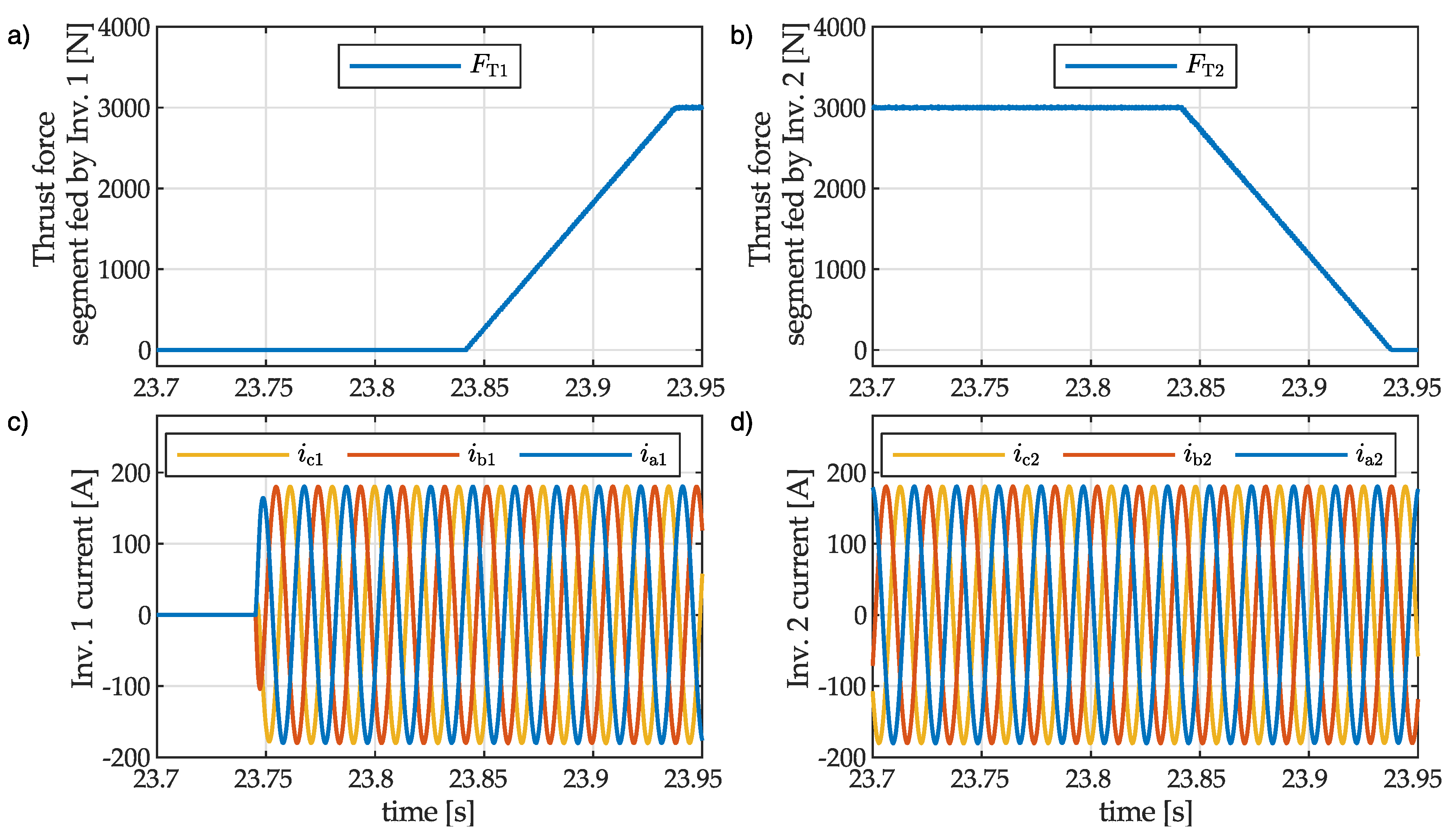
q components of inverter output currents. The operation of each inverter is periodically stopped to switch the output terminals to the succeeding segment of the stator. The switch occurs while the vehicle is entirely above the segment supplied by the another inverter, so it does not affect thrust generation. The current flowing through and thrust generated by two segments during the movement of the vehicle at the junction of these segments are presented in
Figure 14. The illustration starts with the state where the segment fed by inverter 2 generates the whole thrust, and inverter 1 is deactivated. It allows to switch inverter 1 from the section that the vehicle has just left to the section that the vehicle is approaching. When the vehicle reaches the segment fed by inverter 1 at
both succeeding segments are supplied and the thrust is generated by both segments proportionally to the mover presence above the given segment. The total thrust acting on the vehicle is kept constant.
The effect of the system configuration proposed in
Section 3 is illustrated in
Figure 15. The results achieved for two different system typologies are presented for the same driving scenario shown in
Figure 15a,b. For the demonstration purpose, no other balancing methods were applied. DC circuit voltages for the drive system with a standard connection are presented in
Figure 15c. The total DC voltage is constant, but the voltage of each capacitor in the DC circuit is oscillating. The results for the proposed configuration are presented in
Figure 15d. Because the oscillating energy in each inverter, related to the reactive power, is compensating each other, the voltage oscillations in the DC circuit are partially cancelled out. It clearly shows that less effort needs to be made by the balancing algorithm in the proposed topology.
5. Experimental Study
The transportation system concept was verified experimentally using a 2-segment track and vehicle simplified to a bogie. The experimental set-up is presented in
Figure 16 and its parameters are listed in
Table 2. Depending on the tested configuration, the stator is powered by one or two inverters. The block diagram of the control structure is presented
Figure 17. Each inverter is equipped with an LC output filter to reduce the higher harmonics content in the output voltage. In order to provide the required feedback signals, the vehicle speed and position are measured by an on-board system and wireless communication is used to provide feedback to the inverter control unit.
In the experimental study two configurations of the drive system described in
Section 2 have been compared. The results of acceleration and braking at the segment junction are presented in
Figure 18 and
Figure 19. In the single-inverter topology, when the inverter switches from one section to another the stator supply has to be interrupted (
Figure 18a–d). This results in a loss of thrust force, so the vehicle can not keep the required acceleration/deceleration, so the vehicle coasts in that period (
Figure 18e,f). In the multi-inverter topology, periods of inverters operation overlap (
Figure 19a–d). It allows continuous thrust generation, which results in higher average acceleration/deceleration, comparing to single inverter topology (
Figure 19e,f). For multi-inverter topology two configurations described in
Section 3 have been compared in the experimental study. The inverter output current and DC circuit voltages in the parallel operation of inverters in classical topology (
Figure 7a) are presented in
Figure 20. The same experiment scenario has been recreated for the new configuration with inverse phase connections and connected DC mid-point (
Figure 7b). The results shown in
Figure 21 show a significant reduction of DC voltage oscillations. This is possible due to the equalizing current flowing between the mid-point of each inverter (
Figure 21d).
6. Conclusions
In reference to the most common transportation system using rotary motors, systems with linear motors are superior in terms of driving performance and require a different approach to selecting the drive system configuration. The presented research analyzes possible configurations of the linear motor drive system, in which the active part is placed in the infrastructure rather than in the vehicle.
The paper presents the benefits of using multi-inverter systems, i.e., those consisting of several inverters within one section. Thanks to this configuration, it is possible to use shorter segments, i.e., parts of the stator supplied from one inverter, than in single-inverter systems. This allows to lower the requirements for individual inverters. Although the multi-inverter drive system does not have to reduce the total installed power of the converters, it leads to significant technological facilitation in construction of the power electronic system.
The research analyzes different power supply topologies for a long stator motor. A new configuration of the multi-inverter system was presented. The proposed configuration allows to reduce oscillations in the input circuit of the inverter. The simulation and experimental tests have been performed to verify the proposed solution. The experiment results confirm the possibility and legitimacy of implementing the transportation system according to the described configuration. Further work will be carried out on the development of supervisory control algorithms in the multi-section drive system.
7. Patents
This work is subject to a pending European patent application No. EP 21162459.8 filed on 12 March 2021. Patent title: “Long stator linear electric motor”. Applicant name: Hyper Poland Electro S.A., a subsidiary of Nevomo group.
Author Contributions
Conceptualization, M.M., M.N.; methodology, M.M. and M.N.; software, M.M.; validation, M.M., M.N.; formal analysis, M.N.; investigation, M.M. and M.N.; resources, M.N. and P.R.; data curation, M.M. and M.N.; writing—original draft preparation, M.M., M.N. and P.R.; writing—review and editing, M.M., M.N. and P.R.; visualization, M.M. and M.N.; supervision, M.M.; project administration, M.N.; funding acquisition, P.R. All authors have read and agreed to the published version of the manuscript.
Funding
This research and the APC was funded by the National Centre for Research and Development grant number POIR.01.01.01-00-1093/18 from Smart Growth Operational Programme 2014-2020 through the European Regional Development Fund.
Institutional Review Board Statement
Not applicable.
Informed Consent Statement
Not applicable.
Data Availability Statement
Not applicable.
Conflicts of Interest
The authors declare no conflict of interest.
References
- Stephan, R.M.; Pereira, A.O. The Vital Contribution of MagLev Vehicles for the Mobility in Smart Cities. Electronics 2020, 9, 978. [Google Scholar] [CrossRef]
- de Oliveira, R.A.H.; Stephan, R.M.; Ferreira, A.C.; Murta-Pina, J. Design and Innovative Test of a Linear Induction Motor for Urban MagLev Vehicles. IEEE Trans. Ind. Appl. 2020, 56, 6949–6956. [Google Scholar] [CrossRef]
- Hekler, M.; Klühspies, J. Disruptive technologies transforming urban mobility? The role of the ecobee urban maglev system in the seoul traffic vision 2030, South Korea. Transp. Syst. Technol. 2018, 4, 115–123. [Google Scholar] [CrossRef] [Green Version]
- Chen, Y.; Liu, Y.; Guo, D.; Chen, Z.; Li, X. Freight Transit Assignments for an Integrated Network of Road Transportation and Underground Logistics Systems. J. Pipeline Syst. Eng. Pract. 2020, 11, 04020014. [Google Scholar] [CrossRef]
- Nøland, J.K. Prospects and Challenges of the Hyperloop Transportation System: A Systematic Technology Review. IEEE Access 2021, 9, 28439–28458. [Google Scholar] [CrossRef]
- Deng, Z.; Zhang, W.; Zheng, J.; Wang, B.; Ren, Y.; Zheng, X.; Zhang, J. A High-Temperature Superconducting Maglev-Evacuated Tube Transport (HTS Maglev-ETT) Test System. IEEE Trans. Appl. Supercond. 2017, 27, 1–8. [Google Scholar] [CrossRef]
- Haas, T.; Sander, H. Decarbonizing Transport in the European Union: Emission Performance Standards and the Perspectives for a European Green Deal. Sustainability 2020, 12, 8381. [Google Scholar] [CrossRef]
- Hellinger, R.; Mnich, P. Linear Motor-Powered Transportation: History, Present Status, and Future Outlook. Proc. IEEE 2009, 97, 1892–1900. [Google Scholar] [CrossRef]
- Palka, R.; Woronowicz, K. Linear Induction Motors in Transportation Systems. Energies 2021, 14, 2549. [Google Scholar] [CrossRef]
- Cao, R.; Lu, M.; Jiang, N.; Cheng, M. Comparison Between Linear Induction Motor and Linear Flux-Switching Permanent-Magnet Motor for Railway Transportation. IEEE Trans. Ind. Electron. 2019, 66, 9394–9405. [Google Scholar] [CrossRef]
- Suzuki, K.; Kim, Y.J.; Dohmeki, H. Driving Method of Permanent-Magnet Linear Synchronous Motor With the Stationary Discontinuous Armature for Long-Distance Transportation System. IEEE Trans. Ind. Electron. 2012, 59, 2227–2235. [Google Scholar] [CrossRef]
- Hu, Q. Container Transport inside the Port Area and to the Hinterland; TRAIL Research School: Delft, The Netherlands, 2019. [Google Scholar] [CrossRef]
- Shinar, D. Crash causes, countermeasures, and safety policy implications. Accid. Anal. Prev. 2019, 125, 224–231. [Google Scholar] [CrossRef]
- Stumberger, G.; Zarko, D.; Timur Aydemir, M.; Lipo, T. Design and comparison of linear synchronous motor and linear induction motor for electromagnetic aircraft launch system. In Proceedings of the IEEE International Electric Machines and Drives Conference, Madison, WI, USA, 1–4 June 2003; Volume 1, pp. 494–500. [Google Scholar] [CrossRef]
- Rijsenbrij, J.; Pielage, B.; Visser, J. State-of-the-Art on Automated (Underground) Freight Transport Systems for the EU-TREND Project; Technische Universiteit Delft: Delft, The Netherlands, 2006. [Google Scholar]
- Orjuela Castro, J.A.; Casilimas G, W.A.; Herrera Ramirez, M.M. Impact analysis of transport capacity and food safety in Bogota. In Proceedings of the 2015 Workshop on Engineering Applications—International Congress on Engineering (WEA), Bogota, Colombia, 28–30 October 2015; pp. 1–7. [Google Scholar] [CrossRef]
- Marinov, M.; Giubilei, F.; Gerhardt, M.; Özkan, T.; Stergiou, E.; Papadopol, M.; Cabecinha, L. Urban freight movement by rail. J. Transp. Lit. 2013, 7, 87–116. [Google Scholar] [CrossRef] [Green Version]
- Ma, M.; Li, L.; Zhang, J.; Yu, J.; Zhang, H. Investigation of Cross-Coupling Inductances for Long-Stator PM Linear Motor Arranged in Multiple Segments. IEEE Trans. Magn. 2015, 51, 1–4. [Google Scholar] [CrossRef]
- Zhang, Q.; Lin, F.; You, X.; Zheng, T.Q. A Novel Stator Section Crossing Method of Long Stator Linear Synchronous Motor for Maglev Vehicles. In Proceedings of the 2006 CES/IEEE 5th International Power Electronics and Motion Control Conference, Shanghai, China, 14–16 August 2006; Volume 3, pp. 1–5. [Google Scholar] [CrossRef]
- Bitko, A.; Tiapkin, M.; Tolstykh, O.; Rassudov, L.; Volkov, S.; Balkovoi, A.; Tiapkin, G.; Zvolinskiy, K. Comparison of Modular Permanent Magnet Linear Synchronous Motors with Different Winding Layouts of Segmented Stator. In Proceedings of the 2021 28th International Workshop on Electric Drives: Improving Reliability of Electric Drives (IWED), Moscow, Russia, 27–29 January 2021; pp. 1–6. [Google Scholar] [CrossRef]
- Leidhold, R.; Mutschler, P. Speed Sensorless Control of a Long-Stator Linear Synchronous Motor Arranged in Multiple Segments. IEEE Trans. Ind. Electron. 2007, 54, 3246–3254. [Google Scholar] [CrossRef]
- Choi, S.Y.; Lee, C.Y.; Jo, J.M.; Choe, J.H.; Oh, Y.J.; Lee, K.S.; Lim, J.Y. Sub-Sonic Linear Synchronous Motors Using Superconducting Magnets for the Hyperloop. Energies 2019, 12, 4611. [Google Scholar] [CrossRef] [Green Version]
- Ma, K.; Blaabjerg, F. The Impact of Power Switching Devices on the Thermal Performance of a 10 MW Wind Power NPC Converter. Energies 2012, 5, 2559–2577. [Google Scholar] [CrossRef] [Green Version]
- Mazumder, S.K.; Huang, R. A High-power High-frequency and Scalable Multi-megawatt Fuel-cell Inverter for Power Quality and Distributed Generation. In Proceedings of the 2006 International Conference on Power Electronic, Drives and Energy Systems, New Delhi, India, 12–15 December 2006; pp. 1–5. [Google Scholar] [CrossRef]
- Perreault, B.M. Optimizing Operation of Segmented Stator Linear Synchronous Motors. Proc. IEEE 2009, 97, 1777–1785. [Google Scholar] [CrossRef]
- Deng, Z.; Wang, K.; Zhao, L. Research on the Changeover Strategy of Multi-section Long Primary Linear Synchronous Motor for Maglev Vehicle. In Proceedings of the 2019 22nd International Conference on Electrical Machines and Systems (ICEMS), Harbin, China, 11–14 August 2019; pp. 1–5. [Google Scholar] [CrossRef]
- Poorfakhraei, A.; Narimani, M.; Emadi, A. A Review of Multilevel Inverter Topologies in Electric Vehicles: Current Status and Future Trends. IEEE Open J. Power Electron. 2021, 2, 155–170. [Google Scholar] [CrossRef]
- El-Hosainy, A.; Hamed, H.A.; Azazi, H.Z.; El-Kholy, E.E. A review of multilevel inverter topologies, control techniques, and applications. In Proceedings of the 2017 Nineteenth International Middle East Power Systems Conference (MEPCON), Cairo, Egypt, 19–21 December 2017; pp. 1265–1275. [Google Scholar] [CrossRef]
- Mochidate, S.; Matsuo, K.; Obara, H.; Sato, Y. A study on total loss reduction in motor drive systems based on flying capacitor multilevel inverter. In Proceedings of the 2016 19th International Conference on Electrical Machines and Systems (ICEMS), Chiba, Japan, 13–16 November 2016; pp. 1–5. [Google Scholar]
- Wu, M.; Song, Z.; Lv, Z.; Zhou, K.; Cui, Q. A Method for the Simultaneous Suppression of DC Capacitor Fluctuations and Common-Mode Voltage in a Five-Level NPC/H Bridge Inverter. Energies 2019, 12, 779. [Google Scholar] [CrossRef] [Green Version]
- Zhang, J.; Xu, S.; Din, Z.; Hu, X. Hybrid Multilevel Converters: Topologies, Evolutions and Verifications. Energies 2019, 12, 615. [Google Scholar] [CrossRef] [Green Version]
- Liu, J.; Zeng, H.; Tang, W.; Zhou, Y.; Zhang, H.; Xiong, K. The research on security and stability of PWM technology of high-voltage high-power three-level NPC inverter. In Proceedings of the 2015 5th International Conference on Electric Utility Deregulation and Restructuring and Power Technologies (DRPT), Changsha, China, 26–29 November 2015; pp. 2276–2280. [Google Scholar] [CrossRef]
- Qashqai, P.; Sheikholeslami, A.; Vahedi, H.; Al-Haddad, K. A new SVM-based voltage balancing method for five-level NPC inverter. In Proceedings of the 2016 7th Power Electronics and Drive Systems Technologies Conference (PEDSTC), Tehran, Iran, 16–18 February 2016; pp. 511–516. [Google Scholar] [CrossRef]
- Woldegiorgis, D.; Wei, Y.; Mhiesan, H.; Mantooth, A. A New Dc-link Capacitor Voltage Balancing Method for Three-level SVM Strategies Based on Two-level Space Vector Diagram. In Proceedings of the 2020 IEEE 9th International Power Electronics and Motion Control Conference (IPEMC2020-ECCE Asia), Nanjing, China, 29 November–2 December 2020; pp. 1746–1751. [Google Scholar] [CrossRef]
- Cui, D.; Ge, Q. A Novel Hybrid Voltage Balance Method for Five-Level Diode-Clamped Converters. IEEE Trans. Ind. Electron. 2018, 65, 6020–6031. [Google Scholar] [CrossRef]
- Hatti, N.; Hasegawa, K.; Akagi, H. A 6.6-kV Transformerless Motor Drive Using a Five-Level Diode-Clamped PWM Inverter for Energy Savings of Pumps and Blowers. IEEE Trans. Power Electron. 2009, 24, 796–803. [Google Scholar] [CrossRef]
Figure 1.
Block diagram of the multi-section drive system.
Figure 1.
Block diagram of the multi-section drive system.
Figure 2.
Theoretical characteristic of the linear motor power factor in relation to segment length.
Figure 2.
Theoretical characteristic of the linear motor power factor in relation to segment length.
Figure 3.
Block diagram of the single-inverter drive system.
Figure 3.
Block diagram of the single-inverter drive system.
Figure 4.
Generalized thrust profile for the single-inverter drive system.
Figure 4.
Generalized thrust profile for the single-inverter drive system.
Figure 5.
Characteristics of in relation to for various (a) and (b) .
Figure 5.
Characteristics of in relation to for various (a) and (b) .
Figure 6.
Inverter power in relation to for various .
Figure 6.
Inverter power in relation to for various .
Figure 7.
Block diagram of the multi-inverter drive system.
Figure 7.
Block diagram of the multi-inverter drive system.
Figure 8.
Stator segmentation activity sequence.
Figure 8.
Stator segmentation activity sequence.
Figure 9.
Inverter power in relation to in the multi-inverter topology.
Figure 9.
Inverter power in relation to in the multi-inverter topology.
Figure 10.
Multi-level inverters drive system: (a) typical topology, (b) newly proposed topology.
Figure 10.
Multi-level inverters drive system: (a) typical topology, (b) newly proposed topology.
Figure 11.
Drive system topology with a dual 3-level inverter set.
Figure 11.
Drive system topology with a dual 3-level inverter set.
Figure 12.
Functional block diagram of the drive system.
Figure 12.
Functional block diagram of the drive system.
Figure 13.
Example operation of the transportation system—simulation results. (a) commanded and vehicle speed, (b) thrust and resistant force, (c) inverter 1 output current components in the frame, (d) inverter 2 output current components in the frame.
Figure 13.
Example operation of the transportation system—simulation results. (a) commanded and vehicle speed, (b) thrust and resistant force, (c) inverter 1 output current components in the frame, (d) inverter 2 output current components in the frame.
Figure 14.
Thrust genereation during vehicle movement at the stator segment-to-segment connection—simulation results. (a) thrust generated by the stator fed by inverter 1, (b) thrust generated by the stator fed by inverter 2, (c) phase current of inverter 1, (d) phase current of inverter 2.
Figure 14.
Thrust genereation during vehicle movement at the stator segment-to-segment connection—simulation results. (a) thrust generated by the stator fed by inverter 1, (b) thrust generated by the stator fed by inverter 2, (c) phase current of inverter 1, (d) phase current of inverter 2.
Figure 15.
Comparison of DC voltage balancing effectiveness—simulation results. (
a) commanded and vehicle speed, (
b) thrust force, (
c) DC voltages in the system presented in
Figure 10a, (
d) DC voltages in the system presented in
Figure 10b.
Figure 15.
Comparison of DC voltage balancing effectiveness—simulation results. (
a) commanded and vehicle speed, (
b) thrust force, (
c) DC voltages in the system presented in
Figure 10a, (
d) DC voltages in the system presented in
Figure 10b.
Figure 16.
View of the laboratory track and the power electronic set-up.
Figure 16.
View of the laboratory track and the power electronic set-up.
Figure 17.
Block diagram of the control structure.
Figure 17.
Block diagram of the control structure.
Figure 18.
Experimental results for single-inverter configuration, left column—acceleration, right column—deceleration.
Figure 18.
Experimental results for single-inverter configuration, left column—acceleration, right column—deceleration.
Figure 19.
Experimental results for dual-inverter configuration, left column—acceleration, right column—deceleration.
Figure 19.
Experimental results for dual-inverter configuration, left column—acceleration, right column—deceleration.
Figure 20.
DC circuit analysis in single-inverter configuration—experimental results, (a) inverter 1 output current, (b) inverter 2 output current, (c) inverter 1 DC voltages, (d) inverter 2 DC voltages.
Figure 20.
DC circuit analysis in single-inverter configuration—experimental results, (a) inverter 1 output current, (b) inverter 2 output current, (c) inverter 1 DC voltages, (d) inverter 2 DC voltages.
Figure 21.
DC circuit analysis in dual-inverter configuration—experimental results, (a) inverter 1 output current, (b) inverter 2 output current, (c) common DC circuit voltages, (d) current between mid-points of DC circuits.
Figure 21.
DC circuit analysis in dual-inverter configuration—experimental results, (a) inverter 1 output current, (b) inverter 2 output current, (c) common DC circuit voltages, (d) current between mid-points of DC circuits.
Table 1.
Transportation system and drive parameters.
Table 1.
Transportation system and drive parameters.
| Parameter | Symbol | Value | Unit |
|---|
| Max. speed | | 100 | / |
| Vehicle weight | | 1500 | |
| Friction coefficient (viscous) | | 2 | / |
| Rolling friction coefficient | | 0.005 | — |
| Frontal area | | 2 | |
| Drag coefficient | | 0.35 | — |
| Max. thrust | | 10 | |
| Mover length | | 2.5 | |
| Motor type | — | PMLSM | — |
| Stator resistance per meter | | 20 | / |
| Stator inductance per meter | | 112 | / |
Table 2.
Power electronic set-up parameters.
Table 2.
Power electronic set-up parameters.
| Parameter | Value | Unit |
|---|
| Number of inverters | 2 | — |
| Inverter topology | 3-level NPC | — |
| Recitfier topology | 6-pulse | — |
| Switching frequency | 5 | |
| Max. DC voltage topology | 600 | |
| Max. phase current (RMS) | 70 | |
| Output frequency | 0–100 | |
| Output filter inductance | 500 | |
| Output filter capacitance | 50 | |
| Publisher’s Note: MDPI stays neutral with regard to jurisdictional claims in published maps and institutional affiliations. |
© 2021 by the authors. Licensee MDPI, Basel, Switzerland. This article is an open access article distributed under the terms and conditions of the Creative Commons Attribution (CC BY) license (https://creativecommons.org/licenses/by/4.0/).


