1. Introduction
Issues related to electromobility in public transport systems and the improvement of the operational efficiency of public transport are currently of interest to many scientists and engineers [
1,
2,
3,
4,
5,
6]. This coincides with the development of devices ensuring passenger comfort, greater passenger comfort expectations and the intensive advancement of technologies involved in the production of traction batteries [
7,
8], supercapacitors [
9,
10,
11,
12], combustion generators and other energy sources [
9,
13,
14].
The installation of stationary supercapacitors allows the recovery of braking energy for increased energy efficiency, as well as a better pantograph voltage profile [
10,
15]. The authors determined the basic characteristics of this type of device, characterized by high power density. The storage system parameters were determined using an optimization technique. The paper [
9] presents a comparative study that was conducted to select the most suitable control strategy for high power electric vehicles powered by FC, battery and a supercapacitor (SC).
The actual problem of energy management in traction systems is presented in the paper [
16]. A study was conducted on the use of recuperative braking energy of subways in electric transportation. Technical advantages, such as, for example, reducing the voltage fluctuations of the contact line, and economic advantages were presented.
In paper [
1], the authors proposed and analyzed new strategies to increase the energy efficiency of an urban transportation network powered by a catenary. A simulation tool was developed to determine the energy efficiency of the global transport system (vehicles, power line and substation). Simulation results, with and without on-board energy storage and with high resistive overhead lines, are also presented. It is proven that using high line resistance instead of standard line resistance increases the efficiency of the overall system by an additional 5%.
When a trolleybus runs connected to the grid, all its components are powered by the overhead line. However, because the overhead line has to be divided into sections and because it is fitted with switches, crossings and exits, the trolleybus temporarily loses power when running through section (catenary) insulators. As a result, the systems that feed auxiliary circuits are switched off, to be switched on again after a short time. This is undesirable, since power interruptions give rise to high electrical and mechanical overloads, which have a negative effect on the reliability of the vehicle’s sub-assemblies. Moreover, recharging of the DC link capacitors used in the inverter at the input to the trolleybus’ static converter generates surge currents, which also reduces the service life of vehicle components [
17].
Several methods are currently used to ensure the continuity of power supply to auxiliary devices during the passage of a trolleybus through section insulators [
17,
18]. The most common devices employed for this purpose are additional hydraulic pumps, mounted on the traction-motor shaft, which, however, only support the operation of hydraulic systems. On-board 24 V DC batteries are also used to power converters supplying power to auxiliary assembles, but such systems have many limitations. Another method is to use a supercapacitor storage unit, with converters in the intermediate circuit of the static converter, responsible for supplying power to the auxiliary circuits of the trolleybus [
19]. However, this solution requires the use of a static converter that has a much more complex structure and is far more costly. Each trolleybus that is put into service, today, has a drive system that allows the recovery of energy during braking. It therefore only seems reasonable that this energy be employed to power auxiliary devices.
In this light, a new research question must be addressed, as to whether the energy generated as a result of regenerative braking of a trolleybus could be used to power auxiliary devices installed in the trolleybus when it is driving through insulated sections of the overhead contact line. This problem was analysed in the present study. A mathematical model of the trolleybus traction-motor load was developed. It was implemented in Matlab and Simulink.
3. Functional and Formal-Legal Requirements for Trolleybus Auxiliary Devices
Apart from the traction drive system, each trolleybus is equipped with auxiliary devices [
22]. They include air conditioners, 24 [V] batteries along with a control system, a power steering pump, a heating boiler and an air compressor. These elements of equipment ensure the functionality of all systems installed in the trolleybus and maximize passenger comfort. The most important auxiliary devices are shown in
Figure 3.
All auxiliary systems are powered by a static converter and other power electronic devices that provide a number of utility functions and meet the requirements for protection against electric shock. The auxiliary devices in the trolleybus can be supplied directly from the overhead contact line or from the DC links of the traction inverter [
23]. When the trolleybus is powered from the overhead contact line, regardless of the operating mode of the drive, there is always a break in power supply to auxiliary devices during passage through a catenary insulator. Supplying power from traction inverter DC links increases trolleybus performance [
10,
24]. This is due to the fact that during regenerative braking, when the line voltage rises to 780 V, the inverter system switches energy recovery from the overhead contact line to the braking resistor. In this situation, the energy generated by the traction motor also powers the auxiliary devices [
25], as marked with the green arrow in
Figure 2. A block circuit diagram of such a system is shown in
Figure 4.
The block diagram proposed in this paper has been divided into four parts, with the individual components grouped by their functionality. The elements associated directly with the traction drive are referred to as the traction system. This system includes input devices such as a line choke, fuses, main contactors, a contactor for the pre-charge of the traction inverter capacitors and a line filter. The traction system also comprises a traction inverter, a resistor with a braking transistor and an asynchronous traction motor. The off-wire power system is fed from the traction inverter DC links. This system is part of a larger system responsible for supplying energy to the trolleybus when it is running off-wire. The traction inverter DC links also supply power to the heating system and the static converter, which feeds all auxiliary units other than the heating system.
3.1. Functional Requirements
Legal standards require that the power steering system be operative at all times. Whenever the trolleybus is passing through catenary insulators at speeds above 5 km/h, the power steering system must be operative for 10 s. However ensuring the continuity of operation of the 24 V installation poses a huge problem even with short lasting power interruptions. The converter, which charges the 24 V on-board batteries, loses power when the trolleybus travels through a catenary insulator. During this time, the entire 24 V wiring is supplied with energy stored in the on-board batteries. This means the 24 V batteries need to be kept in pristine technical condition. The provisions of the legal standards regarding the operation of auxiliary devices for passage through section insulators of the overhead contact line are given in
Table 2.
Particular focus is placed on those equipment operation requirements that are necessary to meet the applicable standards. Attention is also paid to an additional functionality associated with the continuous operation of systems during runs through catenary insulators, which is not required by legal acts, but is crucial, since the devices are structured in such a way that a lack of power interruptions extends their service life and increases the comfort of passengers and the driver. When certain devices do not need to be powered while the trolleybus is driving through insulators, their functionality is marked as “not required”. In accordance with [
22], during service braking, deceleration must be lower than 2 m/s
2, and deceleration jerk must not exceed 1.5 m/s
3. Pursuant to [
23], the supply voltage of a trolleybus must be within the range of 400–800 V, while the nominal voltage
U of the overhead contact line should be 600 V.
3.2. Electric Shock Protection Requirements
The supply voltage of the DC control wiring should not exceed 60 V, and the cable nominal voltage of the three-phase auxiliary wiring should not be higher than 400 V. The converter charging 24 V batteries should provide double-galvanic isolation from power supply circuits. The first stage of the isolation must have an insulating strength of 2.5 U + 1500 V. For the nominal voltage of the traction network of 600 VDC, the insulating strength is 3000 V for 1 min. The second stage of the isolation must withstand an alternating test voltage of 2300 V for 1 min.
The withstand voltage of the trolleybus’s three-phase wiring against supply voltage must meet the requirements of the test for the first stage of isolation, while the withstand voltage, with respect to the mechanical mass of the trolleybus, must meet the requirements of the second stage of isolation test. The insulation resistance of the two isolation stages must not be less than 1.5 MΩ and 6 MΩ, respectively, before the trolleybus is first put into service. For low-power motors, for which the insulation strength standard is 1800 V for 1 min, the second stage of isolation cannot be provided only by insulating the motor windings. One of the solutions used is to place the motor on insulators. In such a case, it is necessary to ensure that the motor is separated from the device it drives or that the entire set of motors along with their devices are isolated from the vehicle’s mechanical mass. In practice, such solutions do not work well due to operational problems with maintaining the required resistance at the level of 1.5 MΩ. Therefore, an additional separating converter, with double isolation, is used (an intermediate circuit of the static converter, which already provides double isolation for the output converters that feed the auxiliary systems and for the 24 V on-board battery charger).
The autonomous driving system can be turned on after the trolleybus is disconnected from the current collectors using the main contactors. An installation with an autonomous energy source can have a single-stage isolation with the parameters of the second stage of isolation, provided that, when the motor is fed with power from the overhead contact line, it is separated by a charger providing the first stage of isolation. Because it is difficult to maintain the insulation parameters of the traction battery, and the procedure for testing the strength of battery insulation is very complicated, chargers are used that provide double galvanic isolation of the battery from the power supply circuits. In such cases, the battery is tested for insulation resistance against the mechanical mass of the trolleybus, which must be at least 100 Ω/V.
4. Analysis of the Possibility of Providing Power to On-Board Auxiliary Devices through Recuperation of the Kinetic Energy of the Trolleybus
The motion resistances that the trolleybus traction motor must overcome are shown schematically in
Figure 5. They are reflected back to the traction motor shaft. The mathematical model of the traction motor was used to develop a formula for the electromagnetic moment that overcomes these resistances.
The vehicle’s linear motion is given by:
where:
FT—traction force,
FRR—rolling resistance and air resistance,
FG—gradient resistance,
m—vehicle mass,
d—mass moment of inertia caused by the masses of rotating parts,
V—vehicle speed.
The kinetic energy of the vehicle is described by the following equation:
where:
ωk—angular velocity of vehicle wheels,
ωn—angular velocity of traction motor shaft,
Jk—moment of inertia of the wheel,
Js—moment of inertia of the traction motor rotor,
nk—number of vehicle wheels, including twin wheels.
Vehicle speed
V is related to the angular velocity of the wheels
ωk by the following equation:
where:
r—wheel radius.
In turn, the angular speed of the traction motor shaft
ωn is associated with vehicle speed
V as follows:
where:
z—gear transmission ratio.
Thus, the equation that describes the vehicle’s kinetic energy has the following form:
hence:
after transformation, the following equation is obtained:
where
d is the increase in vehicle mass due to rotating masses and equals
Vehicle speed
V is related to the angular velocity of the traction motor’s rotor
ωn by the following equation:
and so
Substituting into Equation (1), we get:
Traction torque
TT is related to traction force
FT by the following equation:
At the same time, the traction torque is related to the driving torque of motor shaft:
where:
TE—driving torque of motor shaft,
TZ—resistance torque of the transmission reflected back to the shaft side of the drive motor.
Rolling resistance and air resistance torque
TRR is related to the resistance force
FRR by the following equation:
At the same time, torque
TRR reflected back to the shaft of the drive motor is given by equation:
From this, the following equation is derived:
Similarly, we obtain:
where
TG—gradient torque reflected back to the side of the drive motor shafts.
By substituting the equations
FT,
FRR and
FG to formula (12), we get:
Multiplying both sides of the equation by
, we obtain:
where:
is a constant parameter representing the inertia of the vehicle
J reflected back to the drive motor shaft. When formula (8) is taken into account, the following is obtained:
Coefficient represents the moment of inertia of the vehicle reflected back to the shaft side of the drive motor.
Formula (22) describes the relationship between the electromagnetic moment of the traction motor and motion resistances.
The final value of motor load torque
TO is given by the following equation:
On approximating, one obtains:
where:
β—coefficient of constant (no-load) losses,
TZ0—No-load loss torque of the transmission system,
TZZ—variable-loss torque related to the transmission of torque
TE by the torque transmission system,
TEN—nominal motor torque.
It was assumed, to simplify the calculations, that torque Tzz was linearly dependent on transmitted torque TE.
The efficiency of the transmission system was defined as:
The formula is valid for torques:
For a two-stage gear transmission system, it can be assumed that ηZN = 0.95 and β = 0.25.
A mechanical equation of the electric motor is:
where:
TE—electromagnetic torque,
TL—load torque,
ωn—angular velocity,
J—moment of inertia.
A model of the two-level inverter is shown in
Figure 6. Voltage vector
is generated from the following equation:
where:
Sa,
Sb,
Sc are the inverter’s three-phase switching functions, which can take the value of 1 or 0;
Vdc—inverter DC link voltage.
Based on the model of an induction motor in a stationary reference frame, the stator flux equation, after Clarke transformation, can be expressed as follows:
where:
,
—
α and
β axis components of flux,
,
—
α and
β axis components of voltage,
,
—
α and
β axis components of current,
RS—stator winding resistance.
Voltage components in axis
α and
β ,
are given by the following equation:
Current components in axis
α and
β ,
are given by formula:
The rotor and stator flux vectors are related by equation:
where:
—stator and rotor flux vectors,
M—stator-to-rotor mutual inductance,
—Blondel coefficient,
Ls—stator inductance,
ω—angular velocity of the rotor,
Tr—rotor torque.
The angle between these two vectors is given by:
The general expression for electromagnetic torque is as follows:
where:
p—number of pole pairs.
The stator flux amplitude is calculated on the basis of two components
and
.
The following formulas summarize the above analysis:
Formula (26) describes the final value of motor load torque T0
Formula (40) describes the value of the traction motor’s electromagnetic torque TE under DTC.
Formula (22) describes the relationship between motor load torque T0 and electromagnetic torque TE
5. Simulation Study
In order to verify whether the auxiliary devices of the trolleybus could be powered using energy recuperated from regenerative braking with the traction motor [
27], a trolleybus passage through a 4 m long catenary insulator was simulated numerically at speeds of 5, 10, 15 and 20 km/h, while maintaining passenger comfort conditions. The simulations were carried out in Matlab and Simulink, based on the circuit diagram of a trolleybus shown in
Figure 7.
A trolleybus with its traction system, electric drive and systems of converters and actuating systems and devices corresponding to the trolleybus equipment were modelled in accordance with
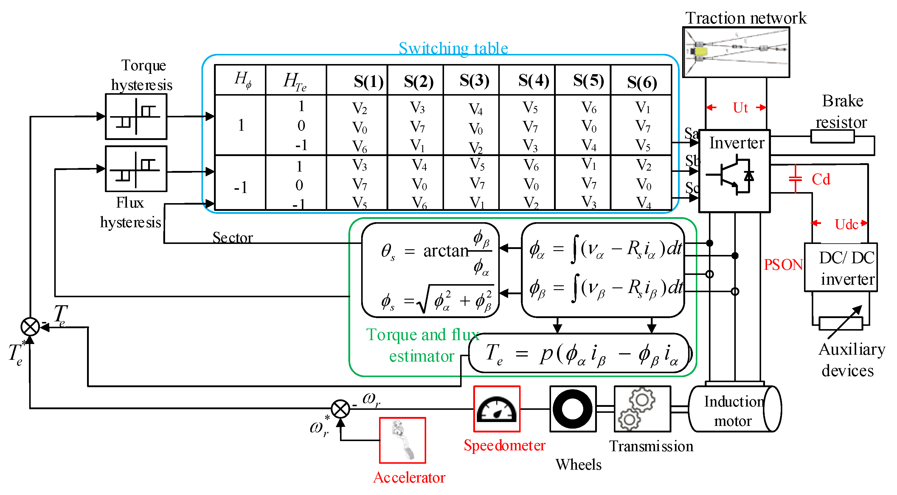
Figure 4. For the main drive system, a circuit diagram of an induction motor fed from a two-level traction converter with DTC was adopted [
26]. The simulation algorithm is shown in
Figure 8.
In compliance with the standards in force, it was assumed that the converters supplying power to auxiliary devices would switch off when the voltage on the DC links of the traction inverter
Udc dropped below 400 V [
28]. The simulations were performed for nominal line voltage. Torque was applied to the traction motor to accelerate the trolleybus to a speed at which the possibility of maintaining the operation of auxiliary devices was tested. At higher speeds, the travel time through a section insulator was correspondingly shorter, as shown in
Table 1. Then, braking torque was applied to the traction motor, so as to ensure that passenger comfort was not affected. Any excess power was lost via the braking resistor, stabilizing the voltage on the DC links of the traction inverter to 780 V.
The simulations were carried out by increasing the load on the traction inverter DC links by increasing the power consumed by the auxiliary devices. The result of the simulation was positive for the load power of the DC links at which the converters did not switch off when the voltage dropped below 400 V as the trolleybus was passing through a section insulator. The parameters used in the simulation are given in
Table 3.
6. Results of Simulation Experiments
Maintenance of the operation of auxiliary devices was simulated during the passage of a trolleybus through catenary insulators at different driving speeds: 5 km/h, 10 km/h, 15 km/h and 20 km/h, and different power levels supplied to the auxiliary devices. The calculation results for the speeds of 5 km/h and 15 km/h are shown in
Figure 9 and
Figure 10, respectively. It was assumed that the trolleybus moved on a flat asphalt road (rolling coefficient µ = 0.01) in windless weather (µ = 0.4).
At the initial speed of 5 km/h, the power required to keep the auxiliary devices operative (high PS ON) while the trolleybus was running through catenary insulators (high PS ON signal) was 0.7 kW (
Figure 9a). The supply voltage of the static converter did not drop below 400 V, and the traction conditions ensuring passenger comfort were not affected. When the DC link of the traction inverter was loaded with the power of 1 kW, voltage dropped below 400 V, and the converters supplying the auxiliary devices switched off, as shown in
Figure 9b. As can be seen in
Figure 9c, increasing the capacitance of the inverter DC links to 50 mF increased power consumption to 2.2 kW. At the speed of 5 [km/h], there was no loss of energy in the braking resistor. It follows that, at low speeds, to use this method of supporting the operation of the auxiliary equipment of the trolleybus, it is necessary to switch off by software the equipment that cannot be supported due to the power consumed by it. Using this method and increasing the DC bus capacity of the traction inverter at 5 km/h, it is possible to provide the functionality required by the legal regulations.
The power required to maintain the operation of auxiliary devices of the trolleybus passing through catenary insulators at the initial speed of 15 km/h was 17 kW (
Figure 10a). The flattening of the DC link voltage curve is a consequence of energy dissipation via the braking resistor at voltages above 780 V. When the DC links were loaded with the power of 18 kW (
Figure 10b), to ensure passenger comfort and attenuate the increase in braking torque, the voltage of the DC links fell below 400 V and the converters switched off. In the later phase of driving through the insulator, energy was lost in the braking resistor, and the converters supplying the auxiliary devices switched on. When the capacitance of the traction inverter DC links was increased to 50 mF (
Figure 10c), the power required to keep the auxiliary devices operative increased to 28 kW. It follows that, at a speed of 15 km/h, the DC bus capacitance of the traction inverter must also be increased in order to ensure the continuity of operation of the auxiliary devices whose functionality is defined as required and additional. With a capacitance of 10 mF, it is necessary to disconnect some of the auxiliary devices by software in order to ensure continuity of power supply to the remaining devices.
7. Conclusions
The paper presents an analysis of the possibility of powering on-board auxiliary devices of a trolleybus with energy from regenerative braking. It was determined, based on real-life and model data, how much power could be recuperated depending on the traction conditions and the capacitance of the traction inverter DC links. The simulation tests show that:
The power of the devices fed from the traction inverter DC links increases as the initial speed of the trolleybus grows
The critical parameter that determines the maximum power of the devices fed from the DC links of the inverter is jerk, da/dt ≤ 1.5 m/s3
At the vehicle speed of v = 5 km/h, power steering is operative only when the capacitance of the traction inverter DC links is considerably increased
At the vehicle speed of v = 15 km/h, it was impossible to maintain the operation of all the devices powered by the static converter; to keep the devices operative, the capacitance of the traction inverter DC links had to be increased five-fold.
In summary, it should be stated that as the demand for power supplied to auxiliary devices in trolleybuses constantly increases, the method of powering auxiliary devices considered in this paper is effective only for a limited range of vehicle speeds and powers of these devices. This means that new power supply solutions for an extended range of operating conditions should be looked for.
A summary of the simulation results is presented in
Figure 11 as a curve of the power that was sufficient to maintain the operation of the auxiliary devices of a trolleybus running through a 4 [m] section insulator versus initial trolleybus speed. The curve was plotted for a traction inverter DC link capacitance of 10 mF and a line voltage of 600 V. The slope of the curve is a consequence of the adopted reaction time of the system to the detection of line voltage loss (5 ms), as well as the constraints on the driving dynamics parameters related to passenger comfort requirements, especially with regard to negative accelerations.
Due to the large influence of the DC bus volume of the traction inverter on the possibility of maintaining the continuity of power supply to the auxiliary equipment of the trolleybus, further research will concern the possibility of using supercapacitors in the intermediate circuit of the static converter and the search for topologies of the trolleybus drive systems, so that it is possible to use autonomous energy sources installed in the trolleybus.


