Abstract
The article presents the concept of application of a multiphase matrix converter (MMC)-based device working as a phase-shifting control device in a power system. A matrix M × M multiphase converter is a simple structure incorporating M × M bidirectional switches, connecting M input phases to M output phases (a square structure is used). The device, in this research and under proposed control, is able to build M output sinusoidal-shape phases (desired output) from parts of input voltages. The proposed MMC-based device can be considered as a new flexible AC transmission system (FACTS) apparatus. Three basic control systems that enabled the creation of output waveforms as the combination of input ones were presented. Both 6 × 6 and 12 × 12 matrix structures were introduced, since 3 × 6 and 3 × 12 transformers are already in use. The mathematical, Simulink, and laboratory models were built to extract characteristic features of the MMC. The chosen “area-based” control procedure was based on finding a common point of area representing a certain switch (connecting a certain input and a certain output) and a time-dependent trajectory. Practical application of the MMC in a power system involves not only MMC analysis, but also the study of application requirements, possible converter topologies, and the development of new, reliable control algorithms. Particular consideration was given to the simplicity of the control and the analysis of the converter properties. The proposed control procedure did not use the PWM technique, but created output in similar way to a multilevel converter.
1. Introduction
In this article, we present the concept of the application of a multiphase matrix converter (MMC)-based device working as a phase-shifting control device in a power system. A matrix M × M multiphase converter is a simple structure incorporating M × M bidirectional switches, connecting M input phases to M output phases (a square structure is used). The device, in this research and under proposed control, is able to build M output sinusoidal-shape phases (desired output) from parts of input voltages. The proposed MMC-based device can be considered as a new flexible AC transmission system (FACTS) apparatus. Three basic control systems that enable the creation of output waveforms as the combination of input ones are presented. Both 6 × 6 and 12 × 12 matrix structures are introduced, since 3 × 6 and 3 × 12 transformers are already in use. The mathematical, Simulink, and laboratory models were built to extract characteristic features of the MMC. The chosen “area-based” control procedure is based on finding common point of area representing a certain switch (connecting a certain input and a certain output) and a time-dependent trajectory. Practical application of the MMC in a power system involves not only MMC analysis, but also the study of application requirements, possible converter topologies, and the development of new, reliable control algorithms. Particular consideration is given to the simplicity of the control and the analysis of the converter properties. The proposed control procedure does not use the PWM technique (it differs from the typical ones [1]), since it creates output in similar way as multilevel converter.
The apparatus we introduce includes M × M matrix switches structured together with M × 3 transformers and filters. The proposed MMC matrix size is 6 × 6 or 12 × 12, since 3 × 6 and 3 × 12 transformers are already available on market. The paper analyzes the application of the MMC in a power system as the system’s series controller. Due to the large amount of power transferred by the MMC during operation (the device is a series-connected element in an SEE line), we propose the application of multiphase MMC structures rather than PWM switching techniques. The secondary voltage of the converter (desired voltage) is built from parts of input voltages. The position of the switch (on/off) depends on running phases of input and the desired sinusoidal secondary voltage. The MMC control algorithm used in this research adopted the so-called “area” approach described in [2,3]. This control strategy is based on geometrical interpretation of the functions describing the actual state of the MMC switches (valves). The algorithm states that the function describing the state of the valve (indexes m, n indicate the position of the valve in an M × M matrix lattice) for a multi-input, multioutput converter can be interpreted as a two-periodical function in space ((0,2π) × (0,2π)), where the values on the 0X and 0Y axes are running phases of the input and output waveforms, respectively. The references regarding MMC control are based on previous authors’ research, since the control procedure is uniquely those authors’ development.
The chosen references include mainly practical analyses of FACTS applications. Hingorani and Gyugyi [4] concentrated on a practical approach to FACTS to enable electrical engineers working in the power industry to understand the principles underlying this advanced system. The second reference [5] describes the possible application of FACTS devices to enhance power-system stability, and the next reference [6] analyzed the optimal location of FACTS in power systems.
The existing solutions are based on application of a DC link, which can connect power systems of different voltage values and different frequencies. Other proposed solutions, as well as the most-popular solution, use transformer-based phase shifters. The paper [7] describes an example of construction of an HV phase-shifting transformer, while paper [8] shows an innovative concept for automatic selection of an optimal tap of the phase-shifting transformer (PST) before it is switched on. The following works analyze the application of PST in real power systems: California [9], Russia [10], India/Nepal [11], and China [12]. The devices (another of which has been built in Poland at the German border) can control power flow up to a few GW. Unfortunately, both devices (PST and DC-link-based shifter) are too slow to be used during dynamic processes; for example, to dump power-system oscillations. The most advanced solution is to build series–parallel UPFC devices, in which active and reactive power flows can be simultaneously inspected [13].
The multiphase structures and control algorithms we propose causes the decrease of phase currents and of switching losses.
2. HV Line Power Flow Control
Electrical power flow (apparent power) through the element consisting only of longitude resistance and reactance (simplified model of the line shown in Figure 1) can be written for a single-phase sinusoidal system in the following manner:

Figure 1.
Simplified circuit diagram for the single-phase line model, where: Vin—the input voltage of the line (voltage at the sending end), Vout—the output voltage of the line (voltage at the receiving end), R—resistance of the line (which may also include the resistance of the transformer), X—line reactance (which may also include the reactance of the transformer), and I—line current.
The goal is to express this relationship as a function of input and output voltages; i.e., a function of their values and the relative angle between them.
The current flowing through the line when ground and mutual capacitances are neglected, since they do not affect line load current (which is true for a large line load), can be stated as:
where: ΔV—voltage drop across the line caused by the flow of current I calculated from the diagram in Figure 2:
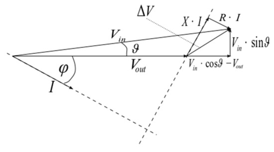
Figure 2.
Phasor diagram of the circuit shown in Figure 1, where: φ—angle between current and output voltage, and υ—angle between Vln and Vout.
Substitution of the above Equations (2) and (3) in the relationship describing apparent power flow through the line gives:
When analysis of a large high-voltage power system is performed, the system resistance is often neglected, since for HV systems, resistance R is more than seven times smaller than system reactance.
When R = 0, then Formula (4) can be written as:
or
Then, the real part of apparent power resembles active power, and the imaginary part is called reactive power. For small υ angles, the increase of this angle causes a fast increase in active power (the function is sine-dependent) and a much slower increase in reactive power (the function is cosine-dependent); thus, to control active power, it is most reasonable to control angle υ.
3. The Structure of the MMC-Based Shifter
The device proposed in this research (Figure 3) is able to control the voltage angle and its value at one of the HV line ends. The device consists of a multiphase matrix converter (MMC), filters, and transformers. The transformers (in this research, 3 × 6 and 3 × 12 transformers were used) can adjust voltage values to powered electronic devices’ capabilities, as well as the number of phases to MMC structure and value of output voltage.

Figure 3.
Proposed device: MMC—converter; T1, T2—transformers; F1A, F1B, F2A, F2B—series and parallel filter systems to support commutation and decrease harmonic content.
Figure 3 shows the proposed structure of the MMC-based device to be mounted in series in a power system line to control voltage at the beginning of this line (value and angle). The transformers are used to lower voltages to levels acceptable for powered electronic devices and to control the voltage value via their tabs. The MMC is used to control voltage angle, and thus the whole device can control line power flow. The frequency of the energy conversion proposed in this research is 50-to-50 or 60-to-60 Hz conversion, since the application is a power system.
4. The Development of the MMC Models
The structure of the MMC was built as an array of two-way, fully controlled switches. The research used the structure of a direct matrix converter, and the proposed control algorithms cannot be recreated using an indirect MMC structure. Paper [14] compared both direct and indirect structures of the MMC, and reference [15] showed the application of direct MC structures in the microgrid.
The circuit diagram shown in Figure 4 illustrates the topology of multiphase MMC working with external circuits. In this circuit, input voltages V1 = [V1,1, V1,2, …, V1,M]T and currents I1 = [I1,1, I1,2, …, I1,M]T, as well as output quantities V2 = [V2,1, V2,2, …, V2,N]T and I2 = [I2,1, I2,2, …, I2,N]T, are determined by external systems with the respect to the MMC structure. When input and output supply are arranged in a star connection and these star points are connected via ground (impedance Z0), then additional quantities U0 and I0 must be introduced to describe current flow and voltage differences between the star points. In general, the multiphase matrix converter (MMC) can be described using the relationships between its input and output quantities (currents and voltages; see Figure 4).

Figure 4.
Circuit diagram of the MMC topology with signals from external systems.
The description of the circuit in Figure 4 can be represented in the following matrix structure:
where:
The solution of the above equation in the time domain is a time-consuming process, thus in this research, a solution using Fourier analysis was proposed. Moreover, the time solution can be difficult to achieve, since the elements of matrixes G (membership functions describing the participation of m-th input in n-th output) depend on running phases of the input and output waveforms where time is a parameter (more in [16]). The control of the inverter was based on the design of the output voltage, as the combination of the fragments of the input voltages. Three basic control concepts were investigated:
- •
- “As close as possible” approach, in which the desired output waveform at a certain instant is built from the input phase, which at this instant is closest to the desired one.
- •
- “Crossing point” approach, in which the desired output voltage is created from part of the certain input phase at the neighborhood of the point in which that input phase crosses the desired output waveform.
- •
- “Two closest” approach, in which the desired output voltage is created from input phases lying in the neighborhood of the desired waveform.
When analyzing the structure of the proposed control algorithms, it is clearly visible that the accuracy of the output waveform construction increases as the number of input phases or input frequency increases. This deduction comes from the fact that during a period of the desired output waveform, there are “more” input waveforms to choose during the creation of the output ones. The number of input phases of the MMC in this research was limited to 6 or 12, since 3 × 6 and 3 × 12 transformers are already in use. The concept of application of a multiphase structure is similar to the control of the multilevel converters for power-system applications, in which the desired output waveform is built from several DC voltage levels.
The field application (power system) imposes additional control criteria:
- •
- Input and output waveforms must be as close as possible to sinusoidal ones;
- •
- No short-circuits are possible at the input and at the output;
- •
- To assure symmetry, the time periods during which a certain input phase is a part of the desired output waveform have to be equal for every input phase;
- •
- The sum of fragments of input currents must cover the entire period of output waveforms (no currentless periods);
- •
- The removal of currentless periods eliminates non-square structures of the MMC, and as previously mentioned, in this research 6 × 6 and 12 × 12 structures were considered.
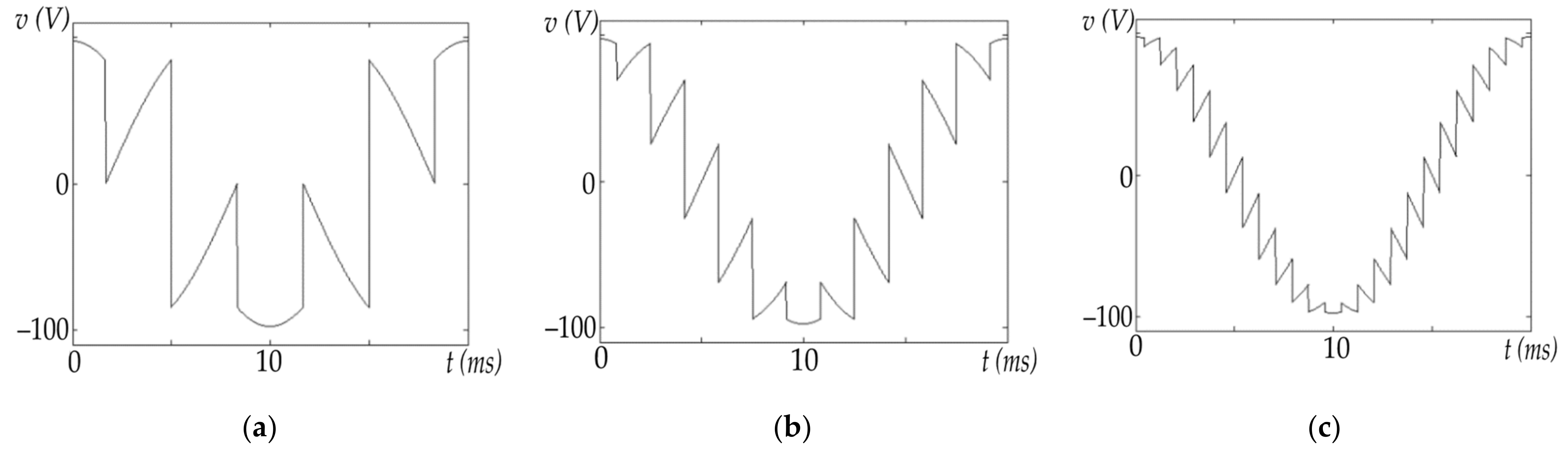
The multiphase structure (more phases than three) of the MMC decreases the currents of the switches (an equal amount of power transfer flowing via three phases is done via multiple structures), decreases the amount of harmonic content, and increases voltage transfer. Moreover, as the number of phases increases, the harmonic order grows (Figure 5).

Figure 5.
Output voltage as function of input phases for the same control procedure: (a) three-phase, (b) six-phase, and (c) 12-phase structures.
5. Proposed MMC Control System and Its Simulink and Mathematical Models
The MMC control system used in this research was based on the so-called “area” approach, in which the output waveforms are created as the combination of the input (energy-sending end) waveforms. The concept of MMC control seems uncomplicated, but further analysis reveals that the state of the switches connecting two phases depends on their mutual position. Taking under consideration sinusoidal waveforms and adopted simplifications, this mutual position can be described as a two-dimensional function where on the “OX” axle is the input running phase and on the “OY” axle is the output running phase of the desired waveforms. The desired output waveforms are of course sinusoidal waveforms with the same frequency as the input ones. Let us take under consideration a control function where at a certain time, the distance between the m input function and the n desired function is shortest, then the fragment of the n function is created from the m input function. In the subspace describing mutual position input phase m and the desired phase n, the point is created and the switch between the m-input and n-output phases is switched on. During simulations for the shown control, the test showed that the function describing the common position of the input and output waveforms created areas in the considered (m,n) subspace. The generation algorithms for those areas for different controls were developed in [17,18].
Since sinusoidal input and output waveforms are created close to the sinusoid, they have to represent certain features characteristic for sinusoids. Moreover, adopted simplifications are additionally coming from the power system. To implement the proposed control, each switch in the MMC must have a generated area (Figure 6). The idea is to generate a conduction area only for the first switch. Since the considered functions are sinusoids of the same frequency, the investigation of only a period-by-period subspace is considered. Then, the areas for the following switches are shifted according to their position in MMC structure.
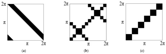
Figure 6.
Shapes of the conduction areas proposed in this research: (a) “crossing point”, (b) “as close as possible”, and (c) “two closest” approaches (derived by authors in [19]).
The “area” approach is used to create an MMC control system [1]. The approach is based on the assumption that the state of the switch connecting a certain input and a certain output of the converter can be determined by running phases (time-dependent arguments of the sinusoidal functions) of these waveforms. Thus, the function describing the switch state can be built as a two-dimensional function in which the axes accordingly represent the running phase at both the input and output (desired output waveform).
The relative position for two phases—one input, one output—can be expressed as a common part of a line called the trajectory and the conduction areas. For the same frequency at both sides, there is no phase shift, and for the sinusoidal inputs and outputs, the shape of the trajectory is a linear function, and there is no switching. The switches on the diagonal for controls “b” and “c” (Figure 6) in the subspace (2π × 2π) are closed permanently, while other ones are always off. For control “a”, the output waveforms are always built from the negative sequence of the input phase, and during the period all switches are switched “on” for the same length of time. When input and output frequencies are constant and equal to ω1 and ω2, then the trajectory is a linear function in the considered space.
where φ is an initial angle difference between the input and output.
Figure 7 shows an example of the conduction area for the “two closest” control concept, and trajectories for 50-to-50 Hz conversion for switch g11 and a 5°, 15°, and 25° applied phase shift. The common parts of the trajectories for each applied angle create a membership function for switch g11 laying between the first input and first output. The functions for other switches are created by shifting the basic conduction area relative to the switch position in the matrix. The result is a 3D 360 × 360 × 36 submatrix (for a 6 × 6 MMC structure and 1° of resolution).

Figure 7.
The creation of the membership functions from the “two closest” control areas for 50-to-50 Hz conversion for switch g11 and applied phase shifts of 5°, 15°, and 25°.
The change of any frequency (at the input or at the output) results in a change of the trajectory angle on the plane (360 × 360).
Figure 8, Figure 9, Figure 10 and Figure 11 were obtained from the Simulink model. The model was developed using standard Simulink blocks. The control procedure was written using an “S” function able to emulate the work processor applied in a real-life model. The control areas for every switch (matrix 360 × 360 × 144 for the entire 12 × 12 MC structure) were introduced as parameters, and frequency (input and output) and required angle shift between input and output voltage as input data. The considered structure of the mathematical model was based on a space–time approach. The state of the switch from the MMC structure shown in Figure 4 can be described as an admittance function. In real-life applications, the “off” currents of the switches can be neglected (these currents consist only of leakage or reverse current of electronic devices, which is usually more than 10,000 times smaller than the conductive current rating). Thus, the final model consisted only of relationships between “on” currents and voltages, and the conductance function became the function of the switch state (membership function). For the proposed approach, running phases are implicit functions of time. The presented type of model is a discrete finite-space transformation and continuous infinite-time transformation. Please note that space transformation is identical to conversion to the symmetrical components, and a continuous infinite-time transformation can be time-expressed by its Fourier analysis.

Figure 8.
The membership functions from the “two closest” control areas for 50-to-50 Hz conversion and 5°, 15°, and 25° shifts according to Figure 7.
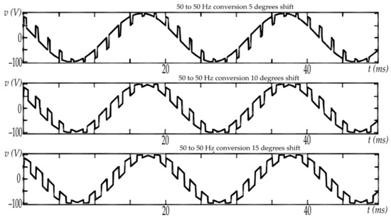
Figure 9.
Output voltage for 12 × 12 MMC for the “two closest” control areas for 50-to-50 Hz conversion and 5°, 10°, and 15° shifts.

Figure 10.
The voltage output of the 6 × 6 MMC working under the “two closest” approach to the control procedure with 10° phase shift versus the input voltage waveform and its harmonic spectrum.
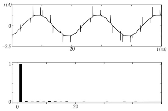
Figure 11.
The input current of the 6 × 6 MMC (sending end of the line) working under the “two closest” approach to the control procedure with 10° phase shift and its harmonic spectrum.
The Simulink model was used to analyze the properties of three proposed control procedures, which are represented by the three area shapes shown in Figure 6. The proposed properties of the MMC-based phase-shifting device were chosen on the basis of earlier investigations. Matlab simulations were used to evaluate voltage transfer, THD and harmonics order for the input and output waveforms (currents and voltages), and linearity of the control. The characteristics obtained from the result of the simulation for the 12 × 12 MC and the “as close as possible” control are presented in Figure 12.

Figure 12.
Example of characteristics for 12 × 12 MMCs: (a) total harmonic distortion (THD) as a function of a phase shift for the “as close as possible” approach; (b) output-voltage phase shift as a function of trajectory shift along the X axis for the “as close as possible” approach; (c) voltage transfer as a function of the input–output phase shift and the “as close as possible” control approach.
During simulations, properties of the MMC such as: voltage transfer, THD and harmonics order for input and output waveforms (currents and voltages), linearity of the control, and dynamic behavior of the MC-based shifter were investigated for different types of load and different properties of the input circuitry. The characteristics obtained from the result of the simulation for the 6 × 6 MC and the “as close as possible” control are presented in Figure 12.
In the above figures, only the 60° period was considered, since for a 6 × 6 MMC, the properties repeat every 360°/6 = 60°.
The simulations showed quite interesting properties, thus a mathematical model and a real 6 × 6 laboratory model were built to further investigate the abilities of the converter in real-life structures.
6. Laboratory Model Construction
Results from the Simulink simulations were confirmed by those from laboratory setup. The MMC was introduced into a five-node, closed-loop power-system model, rated at 30 kVA, 0.4 kV.
The structure of the MMC-based device was the same as in Figure 2. A total of 36 switches (6 × 6 structure) were built using IGBT transistors and a 4-diode structures. The varistors and RC snubbers were used as the transistors’ overvoltage protection. The transformers were 3 to 6 phases and rated at 230 to 110 V (phase voltage). The controller was a custom-made microprocessor board. The controller could handle 12 × 12 MC (144 outputs) with a resolution of 720 points per input-voltage period (0.5° shift resolution). Figure 13a shows the structures of the controller and Figure 13b shows converter two-way switch. Figure 14 presents matrix structure of the MMC device.

Figure 13.
Elements of MMC structure: (a) The functional diagram of the real-life controller; (b) the structure of the applied switch.
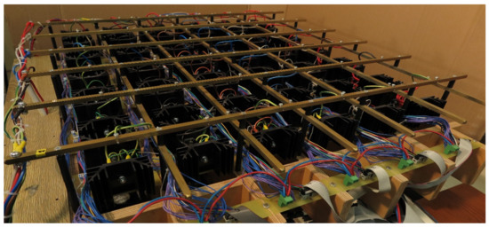
Figure 14.
The 30 kVA-rated MMC laboratory model of the 6 × 6 structure used for evaluation of the converter properties.
The experiments in the real-life laboratory and the results obtained from simulations showed that the output waveform was created from positive sequence input voltage fragments for the “two closest” approach, negative sequence input voltages for the “crossing point” approach, and from both sequences for the “as close as possible” approach.
The MC-based device was connected in series in the power system; thus, when the current was flowing through the device, the sending side (input current of the MMC) current and the voltage of the receiving side (output voltage of the proposed device) were taken under consideration.
For the “as close as possible” approach, the output voltage had the lowest distortions; however, the input current consisted of positive and negative sequences, producing a very distorted device input current.
The results of the simulations from the Simulink models were compared with the signals from real system experiments. Figure 15 and Figure 16 show the results of the analysis.

Figure 15.
Simulation results for the 6 × 6 MMC structure with a 20° shift introduced. Voltage (blue) and current (red) at the output (top) and input (bottom) of the MMC: (a) “crossing point” approach; (b) “as close as possible” approach; (c) “two closest” approach.

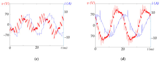
Figure 16.
The results from the real-life laboratory model for the 6 × 6 MMC structure with a 20° shift introduced. Voltage (blue) and current (red): (a) “crossing point” approach input values; (b) “as close as possible” approach input values; (c) “two closest” approach output values; (d) “as close as possible” approach output values.
When the first harmonic of the output current off the MC has an inductive character, the character of first harmonic of input current can be controlled by the shift applied to the MC. It is possible to obtain a purely resistive character of the input current (sending line end).
In the “crossing point” approach, waveforms are built from negative sequences, which creates an input current waveform very close to a sinusoidal one. However, when the power factor at the output has an inductive character, the power factor at the input (taking under consideration only the first harmonic) has the same value, but a capacitive one.
For the “two closest” approach, the desired output waveform is built from the two neighboring (to the desired waveform) input waveforms and only positive sequences are used. Thus, this control system does not change the character of the MMC—if the output has an inductive character, the input current has an inductive character as well.
7. Line Power-Flow Control
The purpose of the research we led during the past 14 years was the application of an MMC-based device in a power system. Before the development of laboratory models (model of the power system and the model of MMC based device), the effects of the devices on line power flow were comprehensively analyzed. Matrix modelling were performed using Matlab Simulink build from standards block and functions (S functions) or using developed mathematical model. An example of the simulation is shown in Figure 17.

Figure 17.
Power-flow interruption after a −12° phase shift in the MC output voltage for the “as close as possible” approach and the 12 × 12 MC.
For a given voltage, values at the both ends, at 110 and 115 kV and with no phase shift between the voltage sources, phase shifts of 12 and −12° were applied to the MMC to show the influence on power flow. The “as close as possible” control was used, since the simulations with “0” phase shift are relatively easy to start because of the lack of MMC interference in the circuit (no switching occurs). The results were very promising—the applied phase shift caused the rapid change of active and reactive power flow through the line. Due to the fact that inductance of the equivalent laboratory circuit was much larger than its resistance, the change of the voltage angle affected the active power flow much more than the reactive power flow (Figure 17 and Figure 18). The current waveforms in both cases, showed the presence of aperiodic components (Figure 19 and Figure 20), which is characteristic for sudden changes in power flow in power systems. Thus, the simulations could help to assess the dynamic response of the MMC-based shifter. The change of the trajectory, which causes the change in power flow, can be done during one step of the controller output upgrade, thus the time is shorter than 0.1 ms (depending on controller processor and control space digitalization). Thus, the controller can be useful for power-flow oscillation dumping and during power-flow interruption stabilization after system faults.

Figure 18.
Power-flow interruption after a 12° phase shift in the MC output voltage for the “as close as possible” approach and the 12 × 12 MC.
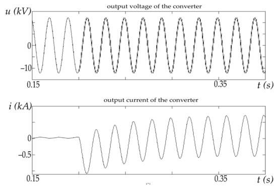
Figure 19.
Output voltage and current of the 12 × 12 MC working between power systems for the “as close as possible” approach and for a −12° phase shift applied at 0.2 s of the simulation.

Figure 20.
Output voltage and current of the 12 × 12 MC working between power systems for the “as close as possible” approach and for a 12° phase shift applied at 0.2 s of the simulation.
8. Discussion
The presented research shows the possibility of the development of an MMC-based phase shifter, inter-system connector, or connector of high- and variable-speed generation to the grid. Our MMC-based device was able to perform not only slow changes in power flow, but also, due its rapid response, could be used as a dumper of power-system oscillations.
Control strategies for a multiphase matrix converter were built using an “area-based” control concept. Then, the work was directed to the determination of the three basic “intuitive” control techniques and corresponding them with shapes of the conduction areas. At first, the concept of the control was modified, and a simple control based on an analog system and comparators was introduced. The areas were generated using Matlab software and then modified to satisfy the stated control criteria. These criteria came from the field of application and included such conditions as: lack of short-circuits at the input and output, continuity of the current, and minimization of waveform distortions. The mathematical model was based on the solution of MMC equations in space–frequency domains. The matrixes describing the dependencies of output and input quantities allowed us to determine their harmonic distribution and symmetrical component content. The model looks promising; however, for a dynamic state, it resulted in a set of differential equations using complex coefficients. Several equation-solution techniques available in Matlab software were tested to solve these equations. If loads in an input element of the MMC were resistive, the outcomes of the simulations performed by authors were similar to the real-life waveforms; however, when inductive load (inductive MD output current) was introduced, the outcome of the simulation was not satisfactory. Thus, before the real-life MMC structure development, an additional model using Matlab Simulink S-functions that was able to emulate microprocessor work was developed. The problems associated with initial conditions, procedures applied by available solvers, and stability of the solution were overcome to achieve simulation results similar to the analog model. To validate the results of the simulations, an experimental real-life model was built in the laboratory. The work included the design of the matrix hardware and the investigation of the commutation problems for the proposed external circuit setups. A bidirectional switch consisting of four diodes and IGBT was chosen, and its commutation processes were assessed. Due to several questions regarding commutation of the converter switches, it was assumed that between the changes in switch states, all switches would be switched “off” to assure that no short-circuits would occur at the input. Later, this procedure was abandoned due to very good switch commutation properties, and small inductances were proposed in series in each input phase to avoid overcurrents.
9. Conclusions
The most important procedure built during the construction of the new MMC-based device was the design control algorithm. The algorithm was built as memory-search technique. At a certain time, a point representing the position on the trajectory was compared with the conduction area for each switch. The control procedure was relatively simple, which was one of the research goals, but required the development of conduction areas for each switch.
THD, control functions, voltage transfer, active and reactive power flows through converter, switch load, and commutation processes were comprehensively analyzed.
Total harmonic distortion was found to be constant for the “crossing point” approach, and phase-shift-dependent for the two other investigated structures. However, the order of introduced harmonics (not their values) was constant for all strategies, which makes filter design easier.
The control functions (the real output voltage shift with respect to the applied trajectory shift) was found to be linear for the “two closest” and “crossing point” approaches, and non-linear for the “as close as possible” approach. This property was attributed to the fact that for the first two approaches, output waveforms were created from the fragments of the inputs with the same sign as the derivative (or the same or opposite to the desired waveform), and the third procedure could be treated as a mix of the first two.
Voltage transfer (for the same matrix structure) was constant for the “crossing point” approach. For the other approaches, it was a function of phase shift, and achieved a maximum (“1”) for shift 0 + k·(360/M) and a minimum for shift 360/2N + k·(360/N), where k is an integer and M is the size of the MMC matrix. It should be noted that the voltage transfer for the “crossing point” approach was equal to the worst case for both other controls.
One of the most interesting properties was the ability of the MMC to change reactive power flow through power line. It was shown that for the “crossing point” approach, if the first harmonic of the output current was lagging the output voltage by angle φ, then the first harmonic of the input current led the first harmonic of the input voltage by φ. This meant that inductive load was seen by the converter input as a capacitive one (phenomenon described in [20]). The “two closest” control did not affect reactive power flow in the circuit. The most interesting case was the “as close as possible” approach, for which the input power factor was a function of trajectory shift. For shift 0 + k·(360/M), the converter did not affect power flow, since M switches were permanently switched “on” and no changes in switch states occurred. However, for the 360/2M + k·(360/M) phase shift, the output of the converter was the same as in the case of the “crossing point” control, introducing the shift of the power factor opposite to the load character. This meant that in every interval (0 + k·(360/M), 0 + (k + 1)·(360/M)), there had to be two points where the unity power factor at the input could be achieved. At these points, the share of the “neighboring” and “crossing” fragments of the input sinusoids in the output waveform must be the same.
For the “crossing point” approach, the conduction times of the switches were identical. The “crossing point” algorithm required all time switching even if the output waveform was identical to the input one. The output waveform distortion in this case for sinusoidal ran constant and equal to the worst case for the “as close as possible” strategy. However, this constant distortion allowed the development of simple filters.
For the two other proposed control strategies (“as close as possible” and “two closest”) the switch conduction time was phase-shift-dependent, and for zero phase shifts, the switches on the diagonal of the MC matrix conducted all the time, and had to carry all power. However, in this case, the interference of the MMC in the system currents and voltages was limited only to the voltage drop across the “on” switch, and thus the waveforms were not distorted.
Author Contributions
Conceptualization, J.S. and T.S.; validation, J.S.; writing—original draft preparation J.S. and T.S.; writing—review and editing, T.S.; funding acquisition, J.S. All authors have read and agreed to the published version of the manuscript.
Funding
This research received no external funding.
Institutional Review Board Statement
Not applicable.
Informed Consent Statement
Not applicable.
Data Availability Statement
Not applicable.
Conflicts of Interest
The authors declare no conflict of interest.
References
- Varajão, D.; Araújo, R.E. Modulation methods for direct and indirect matrix converters: A review. Electronics 2021, 10, 812. [Google Scholar] [CrossRef]
- Sobczyk, T.J. Control strategy of matrix converters. Proc. Eur. Conf. Power Electron. Appl. (EPE) 1993, 4, 93–97. [Google Scholar]
- Sobczyk, T.J.; Sienko, T. Application of matrix converter as a voltage phase controller in power systems. In Proceedings of the International Symposium on Power Electronics, Electrical Drives, Automation and Motion, 2006. SPEEDAM 2006, Taormina, Italy, 23 May 2006; pp. 1322–1325. [Google Scholar] [CrossRef]
- Hingorani, N.G.; Gyugyi, L.; El-Hawary, M. Understanding FACTS: Concepts and Technology of Flexible AC Transmission Systems. Wiley-IEEE Press: New York, NY, USA, 1999; ISBN 978-0-780-33455-7. [Google Scholar]
- Murali, D.; Rajaram, M.; Reka, N. Comparison of facts devices for power system stability enhancement. Int. J. Comput. Appli. 2010, 8, 30–35. [Google Scholar] [CrossRef]
- Shehata, A.A.; Korovkin, N.V.; Tolba, M.A.; Tulsky, V.N. Efficient Utilization of the Power Grid using FACTS devices based on a new Metaheuristic Optimizer. In Proceedings of the 2021 3rd International Youth Conference on Radio Electronics, Electrical and Power Engineering (REEPE), Moscow, Russia, 11 March 2021; pp. 1–7. [Google Scholar] [CrossRef]
- Chen, B.; Fei, W.; Tian, C.; Yang, L.; Gu, J. A High-Voltage “Sen” Transformer: Configuration, Principles, and Applications. Energies 2018, 11, 918. [Google Scholar] [CrossRef] [Green Version]
- Szablicki, M.; Rzepka, P.; Halinka, A.; Sowa, P. Concept of control system for optimal switching of phase shifting transformers. In Proceedings of the 2018 ELEKTRO, Mikulov, Czech Republic, 21 May 2018; pp. 1–5. [Google Scholar] [CrossRef]
- Cai, N.; Khatib, A.R.; Saenz, A.; Bottyan, J. Real-time automation control of a phase-shifting transformer based on mission priorities. In Proceedings of the 2018 IEEE/PES Transmission and Distribution Conference and Exposition (T&D), Denver, CO, USA, 16 April 2018; pp. 1–9. [Google Scholar] [CrossRef]
- Brilinskii, A.S.; Badura, M.A.; Evdokunin, G.A.; Chudny, V.S.; Mingazov, R.I. Phase-Shifting transformer application for dynamic stability enhancement of electric power stations generators. In Proceedings of the 2020 IEEE Conference of Russian Young Researchers in Electrical and Electronic Engineering (EIConRus), St. Petersburg and Moscow, Russia, 27 January 2020; pp. 1176–1178. [Google Scholar] [CrossRef]
- Morrell, T.J.; Eggebraaten, J.G. Applications for phase-shifting transformers in rural power systems. In Proceedings of the 2019 IEEE Rural Electric Power Conference (REPC), Bloomington, MN, USA, 28 April 2019; pp. 70–74. [Google Scholar] [CrossRef]
- Cui, Y.; Yu, Y.; Yang, Z. Application effect evaluation of demonstration project of thyristor-controlled phase shifting transformer in 500kV grid. In Proceedings of the 2015 5th International Conference on Electric Utility Deregulation and Restructuring and Power Technologies (DRPT), Changsha, China, 26 November 2015; pp. 1643–1647. [Google Scholar] [CrossRef]
- Yang, J.; Xu, Z.; Zhang, Z. Analysis of unified power flow controller steady-state power flow regulation capability and its key factors. Energies 2020, 13, 4419. [Google Scholar] [CrossRef]
- Jussila, M.; Tuusa, H. Comparison of direct and indirect matrix converters in induction motor drive. In Proceedings of the IECON 2006—32nd Annual Conference on IEEE Industrial Electronics, Paris, France, 6 November 2006; pp. 1621–1626. [Google Scholar] [CrossRef]
- Gontijo, G.; Soares, M.; Tricarico, T.; Dias, R.; Aredes, M.; Guerrero, J. Direct matrix converter topologies with model predictive current control applied as power interfaces in AC, DC, and hybrid microgrids in islanded and grid-connected modes. Energies 2019, 12, 3302. [Google Scholar] [CrossRef] [Green Version]
- Szczepanik, J. The Multiphase Matrix Converter for Power System Applications, 3rd ed.; Wydawnictwo Politechniki Krakowskiej: Kraków, Poland, 2015; pp. 40–84. ISBN 0860-097X. [Google Scholar]
- Szczepanik, J.; Sienko, T. A new concept of application of multiphase matrix converter in power systems. In Proceedings of the EUROCON 2007—The International Conference on ″Computer as a Tool″, Warsaw, Poland, 9 September 2007; pp. 1535–1540. [Google Scholar] [CrossRef]
- Sienko, T.; Szczepanik, J.; Sobczyk, T.J. Voltage phase controller for power systems. In Proceedings of the 2007 9th International Conference on Electrical Power Quality and Utilisation, Barcelona, Spain, 10 October 2007; pp. 1–6. [Google Scholar] [CrossRef]
- Sieńko, T.; Szczepanik, J. Study of the use of a matrix converterfor building a phase shifter. Acta Energ. 2015, 2, 125–139. [Google Scholar] [CrossRef]
- Sieńko, T.; Szczepanik, J.; Martis, C. Reactive power transfer via matrix converter controlled by the “One Periodical” Algorithm. Energies 2020, 13, 665. [Google Scholar] [CrossRef] [Green Version]


Publisher’s Note: MDPI stays neutral with regard to jurisdictional claims in published maps and institutional affiliations. |
© 2021 by the authors. Licensee MDPI, Basel, Switzerland. This article is an open access article distributed under the terms and conditions of the Creative Commons Attribution (CC BY) license (https://creativecommons.org/licenses/by/4.0/).