Abstract
The power quality analysis is an essential issue in the integration of distributed energy resources to the grid. Recent standards regulate the harmonics disturbances due to the increasing penetration of intermittent energy sources interconnected with the grid employing power converters. This paper aims to analyze the power quality of an interconnected wind turbine system based on a Squirrel Cage Induction Generator (SCIG) driven by an Electromagnetic Frequency Regulator (EFR). The steady state of the EFR harmonic model is developed in the stationary frame based on the conventional induction generator modeling, which allows the study of the harmonic disturbances in the electrical and mechanical variables due to the PWM inverter of the EFR’s armature voltage. There is no electrical connection between the EFR and SCIG, and the results show that the inherent system inertia contributes to the mitigation of the harmonic content at the grid side generated by the switching. In addition to the steady-state results, the Total Rated Distortion (TRD), which considers the harmonics and interharmonics components, was computed and presented a good performance compared to the IEEE 1547 standard and real data extracted of a single Doubly Fed Induction Generator (DFIG). Finally, the harmonic performance of the proposed system was evaluated considering the impact of the equivalent Thevenin impedance of the grid at the Point of Common Coupling (PCC).
1. Introduction
Distributed Energy Resources (DER) are in worldwide expansion as alternatives to the centralized electrical power system, increased by expanding the grid-connected renewable energy sources in a decentralized manner. Due to the higher controllability of power converters, they have been widely used to process the energy generated by these sources. However, one of the main drawbacks in the application of such devices is the lack of natural inertia, which can originate voltage or frequency stability issues, indeed with the increasing penetration of intermittent sources in the electrical grid, as solar and wind turbine topologies [1]. Energy storage applications have been proposed to mitigate the intermittent effect, primary frequency control, and power dispatch regulation [2,3]. However, such technologies increase the complexity due to the addition of distributed energy storage devices as batteries, flywheels, and supercapacitors. Other solutions have been proposed to emulate inertia through control strategies of power converters but are limited to the operational converter constraints [4]. Another drawback of a grid-connected power converter is the harmonics emission generated by the switching process at the Point of Common Coupling (PCC) with the local grid. These effects are even more accentuated in DERs based on intermittent sources, DER interconnected to weak grids, or caused by local nonlinear loads in the PCC [5]. To mitigate such harmonic distortions, several studies have been proposed, using passive filters such as L, LC, and LCL configurations [6]; using active filters [7]; or energy storage systems [8]. Wind turbines (WT) generators have been developed, with most being based on synchronous or induction machines concerning wind energy. They are grouped into the Fixed Speed Wind Turbines (FSWT) or Variable Speed Wind Turbines (VSWT) and classified into four different types based on their technology, each one with its advantages and disadvantages [9]. The widely used topologies of FSWTs are the Squirrel-Cage Induction Generator (SCIG) and Wound-Rotor Induction Generator (WRIG), and for the VSWTs, the Doubly-Fed Induction Generator (DFIG) and the Permanent Magnetic Synchronous Generator (PMSG). The FSWT topologies work at the same rotational speed, whereas the VSWT can change their speed to follow the optimum power point for each wind speed. To achieve this control strategy, VSWTs use a partial or full power converter, and in contrast to FSWTs, are directly grid-connected. By DFIG, at most of the processed power is processed by the partial power converter, while for the PMSG, all generated power is processed by the full converter. Both topologies require passive or active solutions to mitigate the harmonics when connecting with the grid in the PCC. One of the most important power quality issues is to control the voltage and current distortion in the PCC as determined by the standards [10,11]. Many control strategies have been developed to mitigate harmonics in VSWTs [12,13]. The work in [14] proposes a mathematical model and control strategy for DFIG under unbalanced and distorted grid voltage conditions. The current controller consists of a PI regulator and a dual-frequency resonant compensator, tuned twice and six times the grid frequency, designed to regulate the fundamental, the fifth-, and seventh-order harmonic components. Another improved control under harmonically distorted grid considering interharmonics components is detailed in [15]. As discussed in [16], the electrical distortions in DFIG generate disturbances in mechanical variables seen as speed ripples, which are also inversely proportional to the inertia constant. Besides that, each supply harmonic gives rise to a matching current harmonic frequency in the generator’s rotor and creates a set of interharmonic currents. A similar trend can be observed in the torque signal, where several additional pulsating torques arise from the presence of each supply harmonic. As detailed in [17], if these oscillations are not removed in DFIG, the bandwidth of the control loop must be limited to provide sufficient attenuation of the oscillatory component and avoid distorting the current reference. In [18], a mathematical model of DFIG is proposed in the fundamental positive stationary reference frame, , specifically for the fifth- and seventh-order components of grid voltage harmonics, added to experimental results of distortions in stator and rotor currents and the oscillations in the active, reactive powers, as well as the electromagnetic torque in the stator. In [19], a framework is developed for the analysis of harmonics in DFIG caused by non-sinusoidal conditions in the rotor and unbalance in the stator, and the resulting torques produced by these interactions between stator and rotor harmonics. In [20], a frequency-domain harmonic analysis is developed with experimental validation using a 3 kW DFIG grid-connected platform, with a harmonic analysis up to the order. The results presented in [21] show that the injected stator harmonics of the conventional induction motor affect the power quality in the electrical variables and significant oscillations are identified on the mechanical part of the drive system. In [22], a new model is developed using companion harmonic circuit modeling for harmonic distortion analysis for a WT induction generator. The advantage of the proposed model is an easier solution method than the dynamic harmonic domain as it solves algebraic equations instead of state-space differential equations.
Other VSWTs solutions have been developed to avoid grid-connected power converter devices, aiming at the natural increase of the system’s inertia and decreased harmonic content, reducing the complexity inherent to the addition of controllers and filters. For example, the Electromagnetic Frequency Regulator (EFR) consists of an induction machine with the rotor in a squirrel cage and a rotating armature endowed with a three-phase winding that may be fed by a secondary source [23]. A similar topology to the EFR is presented in [24], which have a better frequency regulation performance than DFIG and PMSG, as they do not have natural inertia and must be emulated by control strategies. Despite that, the harmonic performance was not evaluated in the proposed topology. The regulation of a grid-connected SCIG driven by the EFR for maximum power point (MPPT) reference tracking is provided in [25]; however, the inverter was modeled as a sinusoidal voltage source as the purpose of the work was to validate the optimized control strategy.
The major contribution of this paper is the detailed harmonic disturbance modeling and response analysis of the EFR, including the electrical and mechanical subsystems, as it was not covered in the related previous papers [23,24,25,26,27]. The mathematical model analyzes the harmonics components and the oscillations in active power and electromagnetic torque when the EFR armature voltage is distorted. The models allow the study of harmonic distortions and the power quality indexes reflected in the PCC side of a SCIG driven by an EFR excited by the EFR inverter. In addition, some results show the influence of a weak grid related to the increased harmonic distortion. A subsequent contribution of this paper is the comparison of results obtained using the proposed WT with the IEEE 1547 standard, which regulates the power quality indexes in the interconnection of DERs with the grid. Finally, the use of a real case of collected data of a DFIG harmonic distortion in PCC is used as an element of comparison with the SCIG driven by the EFR, as both are VSWT and based on the conventional induction generator.
This work is subdivided into three main topics. In Section 2, the generic steady-state harmonic model of the EFR is provided. First, the mathematical model is developed in the fundamental inverter frequency of the stationary frame . Then, the derived expressions of powers and torque, considering the EFR’s dynamic model, aiming the impact of the EFR armature switching voltage through the EFR’s rotor, mechanical coupling with the SCIG’s shaft, and the reflection in the SCIG’s stator electrical variables. Section 3 presents the harmonic analysis of steady-state results of the electrical and mechanical variables of a 2 MW grid-connected SCIG driven by an EFR based on the developed model. Finally, Section 4 discusses the power quality indexes based on the IEEE 1547-2018 standard, some parameters of comparison with a real case of a DFIG collected data, and the impact of the grid impedance seen at PCC in the harmonic performance.
2. Steady State Harmonic Model of EFR-Driven Generation System
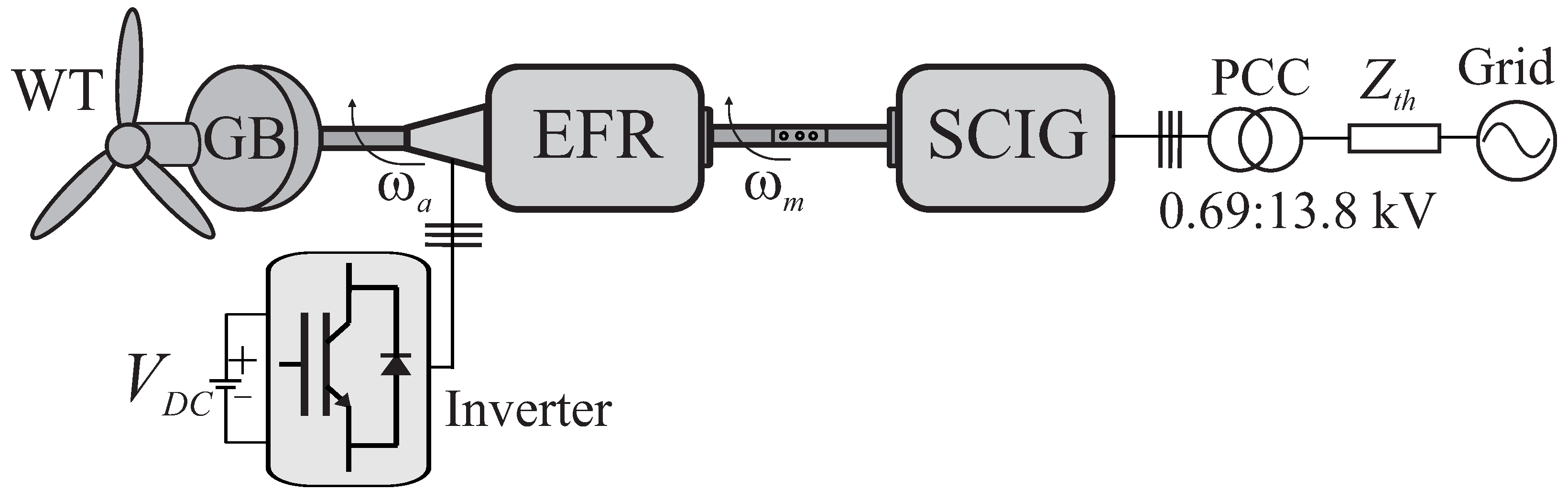
The Electromagnetic Frequency Regulator (EFR) consists of an induction machine with a squirrel cage rotor and a rotating armature. A frequency inverter is used to adjust the electric current injected into the armature and deliver a desired angular speed to the Squirrel Cage Induction Generator (SCIG) rotor, despite the variable angular speed of the wind turbine (WT) [25]. The general steady-state equivalent model of induction machines in is well accepted [14,22], and only the EFR harmonics modeling is presented in this paper. It is assumed that one DER unity based on SCIG and driven by an EFR is interconnected to the Point of Common Coupling (PCC) through equivalent Thevenin impedance () of the grid as shown in the Figure 1. The whole system contains a WT connected to the gearbox (GB), the EFR, a three-phase power inverter connected to the EFR’s armature through collector rings, and a SCIG whose rotor is mechanically coupled to the EFR’s rotor (cage). The stator windings of the SCIG are connected directly to the PCC by a three-phase transformer to adjust the values of the generated voltage to the distribution grid voltages ( kV). The system impedance consists of the grid and transformer impedances. The transformer is modeled as an ideal transformer, with no magnetic saturation and having only a series inductor (). Therefore, the total system inductance is a sum of the grid and transformer inductances (). The grid is modeled as an ideal three-phase voltage source of 690 V and 60 Hz in the low-voltage side of the transformer.
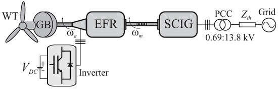
Figure 1.
SCIG grid-connected driven by an Electromagnetic Frequency Regulator (EFR).
This paper aims to analyze the effect of the harmonic components due to nonsinusoidal armature injection resulting from inverter operation. Therefore, distortions arising from the oscillations of the wind speed in power generated by the turbine will not be considered. This case is not exactly equal to real conditions but is considered for analyzing the independent effects of distortions originated by mechanical oscillations and distortions on the electrical part. A general description of the system is presented first to develop EFR-based harmonic modeling to assess the frequency harmonics analysis. The harmonic sources considered here are the characteristic ones inherited from the inverter switching process. The nonsinusoidal armature voltages are decomposed into harmonic components, and their corresponding sequences are identified. Then, the induced harmonics in the EFR’s rotor are analyzed and computed, from which the torques and angular mechanical speeds produced by these interactions between stator and rotor harmonic components are found. In addition, power quality indexes are checked on the grid side to analyze the influence of the converter on the PCC.
2.1. Wind Turbine Model
The mathematical wind turbine model (1) describes the relationship between the wind speed and the mechanical power extracted from the wind [22,28],
where is air density; the turbine blades area; the power coefficient, which describes the aerodynamic performance of the turbine and is a function of the tip-speed ratio () and pitch-blade (); and is the wind speed. In the tip-speed ratio formula, is the turbine angular speed. can be obtained from (2) and has a theoretical maximum value equal to according the Betz limit [29].
the mechanical torque produced by the wind turbine [25] can be obtained from (3) as
A gearbox is used to multiply the speed and reduce the torque at the wind turbine output. This component is defined by (4) as
where is the turbine torque, and and are the angular speed and torque of the EFR armature in the high-speed side of the gearbox, respectively.
2.2. EFR Inverter and PWM Modulation Strategy
The static converter regulates the frequency and amplitude of the voltage applied to the EFR armature windings, usually by a Pulse Width Modulation (PWM) strategy. These harmonics consist of local spectra centered on multiples of the switching frequency () with sidebands in multiples of the fundamental reference frequency of the inverter (). Therefore, the frequencies resulting from the switching effect appear in both the voltage and current spectrum of the EFR armature windings and are described by (5) [30],
the values of the l and m indices of the resulting harmonics depend on several factors, such as the PWM technique used, converter topology, and switching scheme. In this work, a conventional two-level three-phase inverter with optimized PWM modulation was used, increasing linear region avoiding extra distortions at the output voltage due to the overmodulation. Besides that, the switching dead time was not considered, which could result in additional low-order harmonics. In this strategy, the reference voltages , , and are added to an auxiliary voltage variable () in (6)–(8) to achieve an improved PWM waveform.
with
where , , and are the new reference voltages compared to the triangular to generate the switching pulses; = {} and = {}; and is the distribution factor and determine the free-wheeling time interval distributed throughout the switching period. In this work, is chosen in order to generate a symmetrical reference voltage waveform which represents the lowest Total Harmonic Distortion (THD) [31]. Furthermore, note that the is added equally in all reference voltage phases and, therefore, is eliminated in the composition of the line voltages (, and ).
2.3. Harmonic Model in the Electromagnetic Frequency Regulator (EFR)
Harmonics components in the EFR armature windings have their origins in the nonsinusoidal voltages generated by the inverter. These harmonics also induce currents in the rotor windings and are influenced by the respective harmonic sequence (positive, negative, or zero). Similarly, the same analysis can be made for the harmonic inductions from the rotor to the SCIG stator. Under balanced and distorted voltage conditions, no zero-sequence component is assumed, and only the positive () and negative () with , harmonics frequency are taken into consideration in this work, because they are the most common in electrical systems as explained in [21,22]. Therefore, for a complete study of the harmonics and their influence on the power quality generated at the grid side, it is important an adequate model of these inductions which occur in both EFR and SCIG electrical machines.
The armature electrical rotating field is the sum of the angular speed of the inverter currents () with the mechanical speed of the turbine in the high-speed side of the gearbox () as both rotate in the same direction, defined by the phase sequence in the armature currents. The mechanical speed of the turbine and the mechanical speed of the EFR rotor shaft () are multiplied by the number of pole pairs of the machine to match the angular frequency of the electrical currents of the armature windings, which is connected through slip rings to the inverter output. Therefore, the absolute electrical armature angular speed () can be defined by (10), for the fundamental frequency inverter component as
and the EFR slip () of the rotating field in relation to the EFR rotor, can be calculated by (11),
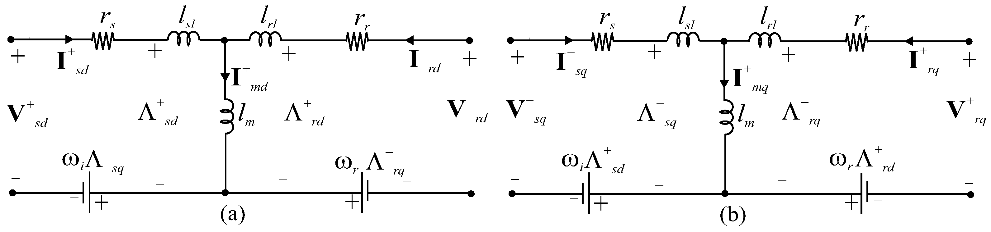
where is the slip angular speed. The EFR electrical model (Figure 2) consists of a similar set of squirrel cage induction machines. Equation (12) in the fundamental positive synchronous reference frame () considering the relative electrical speed of the EFR armature () [13]. The superscript + indicates the referential frame related to the fundamental positive frequency () of the voltage applied to armature . Although the armature is not static in the EFR, the subscripts s for variables relative to the armature and r for the rotor are used to follow the convention widely used in the literature [14].
where , , and are the armature voltage, current, and flux, respectively, and , , and are rotor voltage, current, and flux, respectively, in frame. As both electrical machines are squirrel cage type, the rotor voltages are . The electric currents and flux linkages in a steady state condition are defined by (13),
where and . The currents also can be calculated by (14),
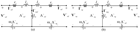
Figure 2.
Equivalent circuit of EFR in synchronous reference frame: (a) and (b) .
Assuming the inverter reference voltage aligned with the axis in frame, the modeling equations can be simplified, with and , which corresponds to a signal in the rotating frame with the fundamental frequency . Including the positive and negative harmonic armature injection, the armature angular speed of the harmonics components () are calculated in (15),
where h is the harmonic order; + is used for a positive sequence harmonics, represented by with ); and − for a negative sequence harmonics, represented by with , for . This components also generates harmonic slips () defined by (16),
As the EFR control is made in reference frame with armature () and rotor angular speed () related to the fundamental frequency of the inverter (), and are a component in this reference, and the armature and rotor current harmonic components are represented by space vectors that rotate with frequency calculated in hertz by (17), in ,
for instance, the harmonic in the armature voltage is negative sequence, and according to (17), this frequency component is represented by in . The harmonic is positive sequence and . Therefore, the harmonics components in reference frame behave as the components () oscillating around the fundamental frequency () in this frame, as represented by (18).
where the superscript “+” represents the fundamental reference frame and denotes the variables under analysis, such as armature and rotor voltages, currents, and fluxes. These space vectors can be expressed, in a generic form, as a function of their positive sequence of the fundamental and their harmonic components by a transformation of armature and rotor variables in by (19) as is well explained in [14,19].
and for rotor by (20),
x denotes the number of harmonics considered for analysis, and note that the harmonic components of and both oscillate at frequencies in reference frame.
2.3.1. Electrical Power and Mechanical Behaviour
The instantaneous three-phase power can be calculated by the armature circuit (21),
where the superscript represents the conjugate vector, is the active power, and the reactive power of the EFR’s armature. is the electromagnetic power and is determined by the interaction between the concatenated fluxes of the armature and the rotor. According to (19), the voltage and current of the armature have the same harmonic components, and can be expressed as shown in (22) and (23) for the current conjugate, respectively.
substituting (22) and (23) in (21) and decomposing the total instantaneous power into components with the same angular frequency yields (24),
decomposing (24) the total power into different powers components, the active power can be simplified by (25),
and the reactive power by (26),
Following the previous procedure, the simplified expression of the electromagnetic power (21) results in (27),
where the coefficients , , , , , , , , , , , , , , and in (25)–(27) are shown in Appendix A, neglecting the armature resistance . The electromagnetic torque developed () is determined by the electromagnetic power in (21) and obtained by (28). It is worth noting, positive-sequence harmonics contribute to torque in the forward direction, and negative-sequence harmonics provide torque in the backward rotation sense.
Two dynamic angular acceleration equations are required for EFR as both the armature and rotor are movable. The armature is accelerated by the wind turbine torque () at the high-speed side of the gearbox and braked by the electromagnetic torque () of the EFR, which is also responsible for accelerating the rotor. The EFR rotor is mechanically coupled to the SCIG rotor. They have the same mechanical speed () and electromagnetic torque, by a steady state of . Their slips present opposite signs, as the EFR presents motor operation () with relation to the SCIG (). The balance equation that describes the acceleration of the EFR armature and can be written as
where is the sum of the inertia of the turbine added to the EFR rotating armature in the high-speed side of the gearbox and is the armature friction coefficient. The balance equation for the EFR rotor is identical to the conventional induction machine, as the electromagnetic torque accelerates the rotor (), which is braked by the mechanical torque () at the SCIG shaft,
is the sum of the inertia of the EFR rotor with the induction generator rotor, and is the rotor friction coefficient. In steady state, the mechanical torque in the armature is equal to the torque available on the EFR shaft, and equals to the electromagnetic torque of the SCIG, but with a negative value ().
According to (22) and (23), harmonics in the armature supply voltage will cause harmonic currents on both the armature and rotor sides of the EFR. Due to the interactions between the MMFs established by the armature and rotor currents, harmonics exist in the electromagnetic torque (28) which will lead to speed ripples (), that can generate noise and vibrations in the mechanical shaft that propagate to the SCIG. However, as the EFR and SCIG have inherent inertia through its mechanical coupling, it is expected the natural smoothing of the high-order harmonics produced by the inverter, due to the reduced bandwidth imposed by the moment of inertia of the coupling between the rotors (see in [17]).
2.4. System Description and MPPT Control
This work considers the optimal control mode once the input value of the wind speed is available and determines the optimum slip value for achieving Maximum Power Point Tracking (MPPT) operation. The complete strategy is detailed in [25] but is synthesized in this paper to facilitate the proposed analysis. The maximum value of , corresponding to , for . The desired torque in the generator axis for each wind speed () can be calculated from (3) resulting in (31). The EFR receives a variable speed and delivers the desired speed in the shaft. Then, when connecting the SCIG to the EFR rotor shaft, it is possible to control the generator torque through the SCIG slip, solving the second-order equation in (32), and electing the real root with the lowest absolute value, corresponding to improved performance.
where , , ; is the stator synchronous angular frequency; and are the SCIG resistance and reactance of the SCIG rotor windings, respectively; and and are calculated by (33),
where is the grid phase voltage, is the magnetizing reactance, and is the reactance of the SCIG stator windings. The mechanical angular speed of reference is determined by (34), considering the SCIG number of pole pairs ,
and the armature speed reference is determined by (1) in the high-speed side of the gearbox (4) for an optimum wind power utilization as calculated in (35).
Finally, the frequency regulated by the inverter is determined by the scalar control. In this method, the mechanical speed is controlled indirectly by the inverter, adjusting the frequency of the electrical currents in the EFR armature, according to (11) and as explained in [25]. The detailed parameters of the complete system setup are listed in Table 1 based on actual wind turbine and induction machines.

Table 1.
EFR, SCIG, and system parameters.
The moment of inertia J can be obtained in terms of inertia constant K by (36),
is rated angular speed in mechanical radians per second, and is the volt-ampere rating. In order to generalize the results, we considered the following operational conditions for the study of the EFR and SCIG behavior in the harmonics:
- System operation with a constant wind speed input and the EFR is regulated with constant torque and speed.
- The winding distribution in the machines is sinusoidal, and thus there are no MMF space harmonics and slot harmonics. Sinusoidal and balanced grid voltages at the PCC are considered.
- Magnetic saturation and the electrical losses in the inverter are neglected, and the system is in a steady state with all derivatives equal to zero.
- Considering the harmonic model of the EFR and SCIG in Section 2.3.1, the levels of the harmonics of the armature and PCC voltages and currents are followed. Moreover, the Total Rated Distortion (TRD) of voltages and currents, considering the interharmonics at the PCC, oscillations in the electromagnetic torque, and angular mechanical speed are monitored.
3. Test Case 1: Harmonic Analysis of a 2MW Grid-Connected SCIG Driven by an EFR
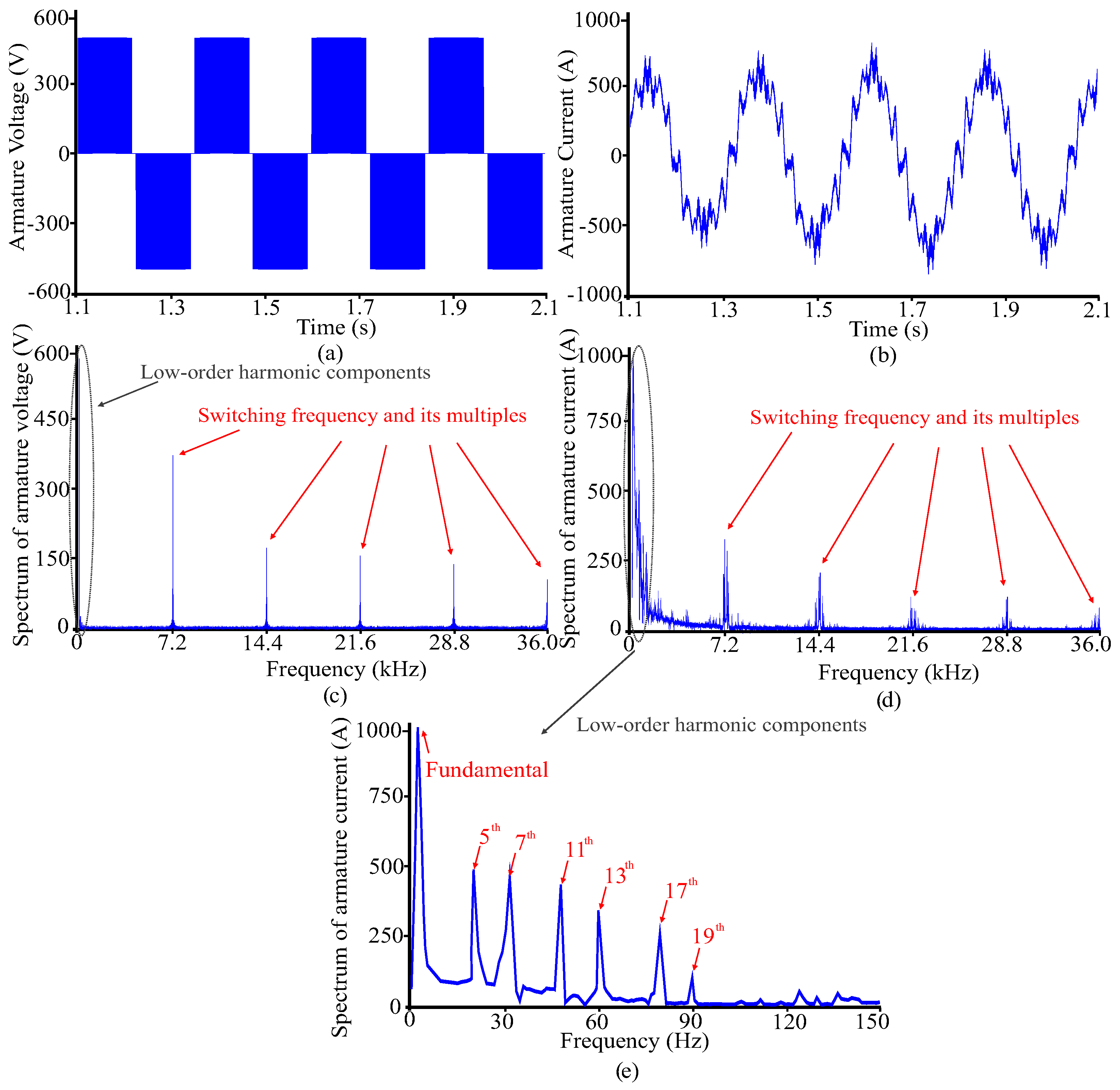
A simulation program was developed using a Scilab platform, and a 2nd order Trapezoidal Algorithm was adopted to solve the differential Equations (12), (29), and (30) in the time domain, with a sampling frequency of kHz. The numerical method and the computer simulation were developed using fully the Scilab native language without using any toolbox. In order to evaluate the individual harmonics components, the system was simulated for delivering the nominal output power by a wind speed of m/s considered as input data. Note that during a normal operation of a wind turbine, the wind is changing continuously and, therefore, the slip of the machines may be varying in the same way. For this case, the SCIG slip is regulated to their reference value of , which by (34) gives rad/s and kNm, in MPPT operation. The inverter is regulated with nominal pole voltage amplitude of V (Figure 3a) and fundamental frequency of Hz applied to the EFR armature. To compute the proportion between the harmonic component concerning the fundamental, the Individual Harmonic Distortion (IHD) is used in this work, which is a ratio between the RMS value of each harmonic by the fundamental component, as defined by (37),
where h is the harmonic order and H represents the variable under analysis, such as voltage, current, and torque. is the fundamental component in the natural frame and a level in frame. The armature line current in phase a is plotted in Figure 3b. Figure 3c,d shows the low-order harmonics around and high-order harmonics in the armature voltages and currents of the spectrum, mainly located in the PWM inverter switching frequency of kHz and its multiples, with the side bands . Figure 3e presents the zoom in low-order spectrum of EFR armature current. The fundamental and some accentuated positive and negative sequence harmonics are highlighted as , , , , , corresponding to Hz, Hz, Hz, Hz and Hz, respectively. As expected, such predominant harmonic frequencies occur in with , known as the characteristic harmonics of the inverter.
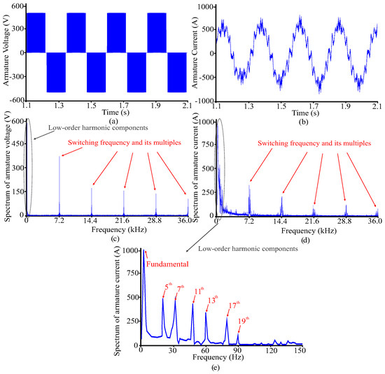
Figure 3.
(a) Pole voltage applied to the EFR armature windings (). (b) Line current in phase a of the EFR armature (). (c) Frequency spectrum of . (d) Frequency spectrum of . (e) Zoom of the low-order harmonic components of .
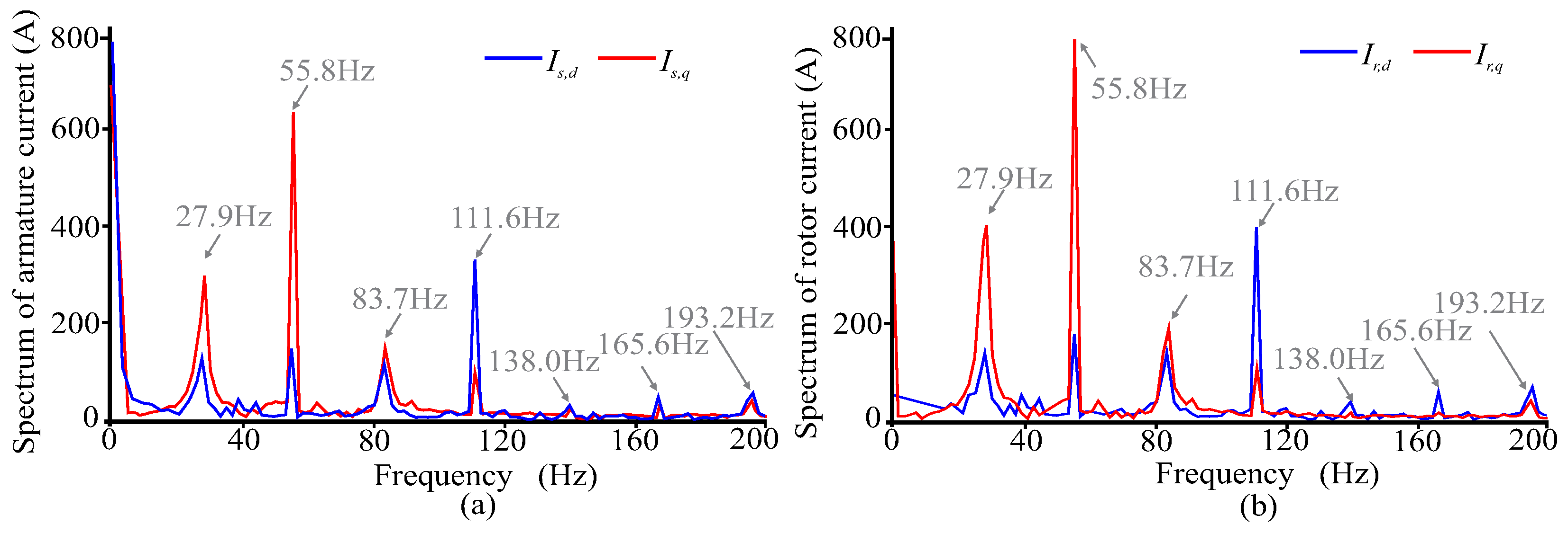
In addition to the frequency analysis in Figure 3, the effect of the low-order harmonics frequencies at the EFR armature and rotor currents in frame must be evaluated. The armature harmonics currents establish rotating magnetic fields, inducing harmonic currents frequencies to the EFR rotor as indicated in Figure 4. The rotor current harmonic space vectors have angular speed defined by (17) in . As the harmonic is a negative sequence component, its space vector angular speed is equal to Hz. Similarly, Hz, Hz, etc. This explains all the predominant multiples of six of the inverter fundamental frequency in the armature and rotor currents of the EFR as indicated in Figure 4a,b. Furthermore, the main difference between both armature and rotor EFR’s currents is observed in the fundamental component, corresponding to the dc levels in the frequency spectrum. As shown in Figure 4a,b, the rotor currents have a lower fundamental component than armature, and such a difference can be explained by the increase in the rotor resistance () in the model of Figure 2, which is inversely proportional of the EFR’s slip.
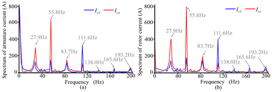
Figure 4.
EFR currents frequency spectrum in . (a) Armature (blue) and (red). (b) Rotor (blue) and (red).
3.1. Electromagnetic Torque and Mechanical Response
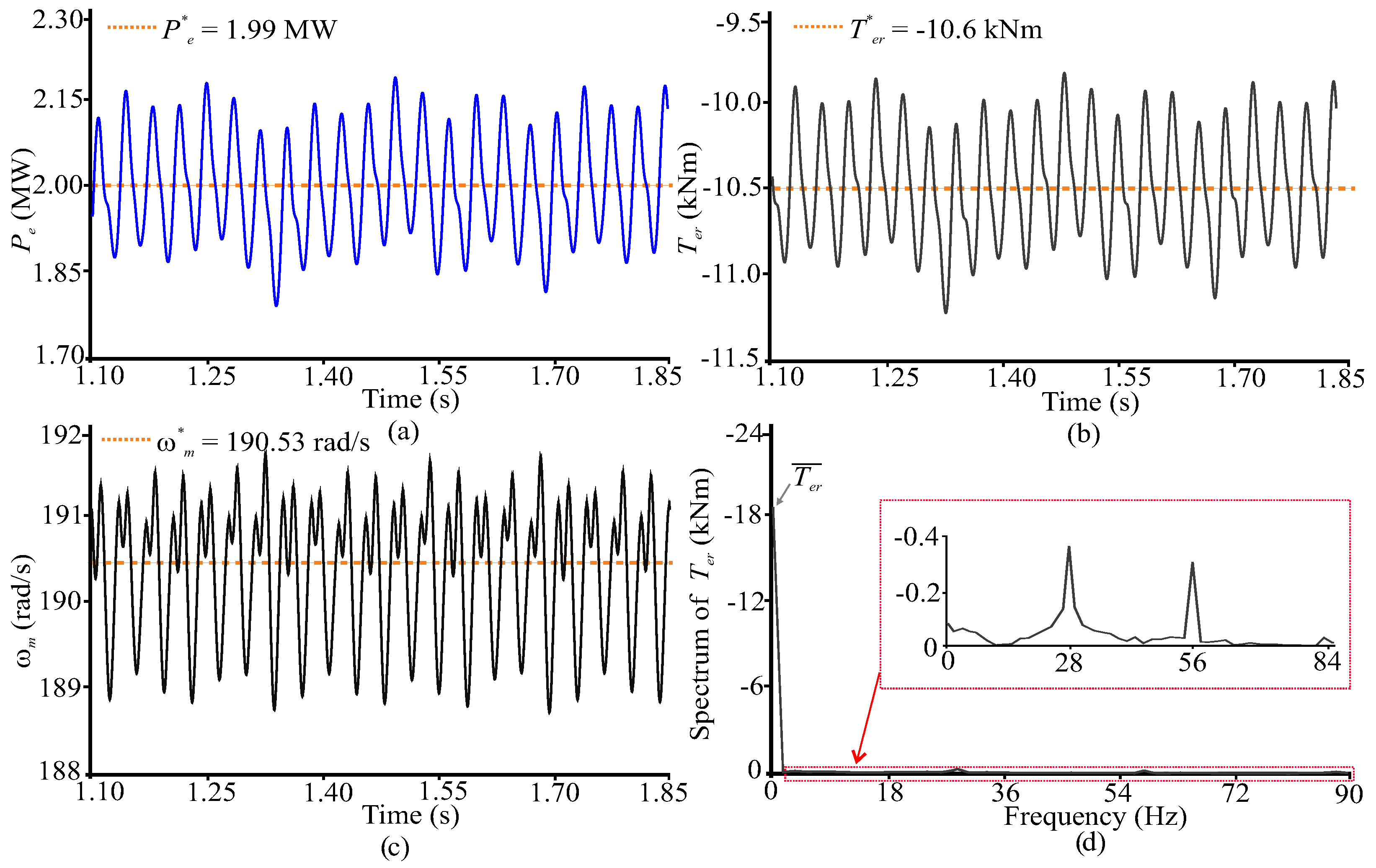
In a steady-state operation without harmonic distortion, the electromagnetic power, torque, and mechanical speed have a constant value given by the controller reference. However, due to the harmonics inserted by the inverter, significant harmonics components appear and are observed as oscillations around these reference variables, as indicated in Figure 5. As observed in (27) and (28) and by analysis of Figure 5, the harmonic cross-coupling produce the odd zero-sequence harmonic in the electromechanical system.
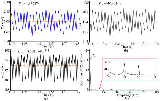
Figure 5.
Steady-state electromechanical variables for m/s. (a) Instantaneous active power () and power reference (). (b) Mechanical torque () and reference torque (). (c) Mechanical speed () and reference speed (). (d) Mechanical torque frequency spectrum.
Figure 5a shows power oscillations kW, a torque ripple of Nm in Figure 5b and a speed ripple rad/s is seen in Figure 5c. Figure 5d shows that the direct component is predominant in the electromagnetic torque. However, the and harmonics are the principal components of its oscillations, with and of the level, respectively. These speed ripples are ultimately reflected in the rotor current spectrum of the SCIG and will be discussed in the next subsection. Furthermore, the PWM’s high-order frequencies and multiples do not influence the machine’s dynamical behavior as the switching frequency is far above the critical mechanical frequencies. Note that the dynamic response on shaft torques under this condition is much different from step wind excitation because of the rotor mechanical inertia, the step wind cannot increase the torque abruptly, and only the steady-state variables are presented.
3.2. Impact of EFR Armature Harmonics Components at the PCC Side
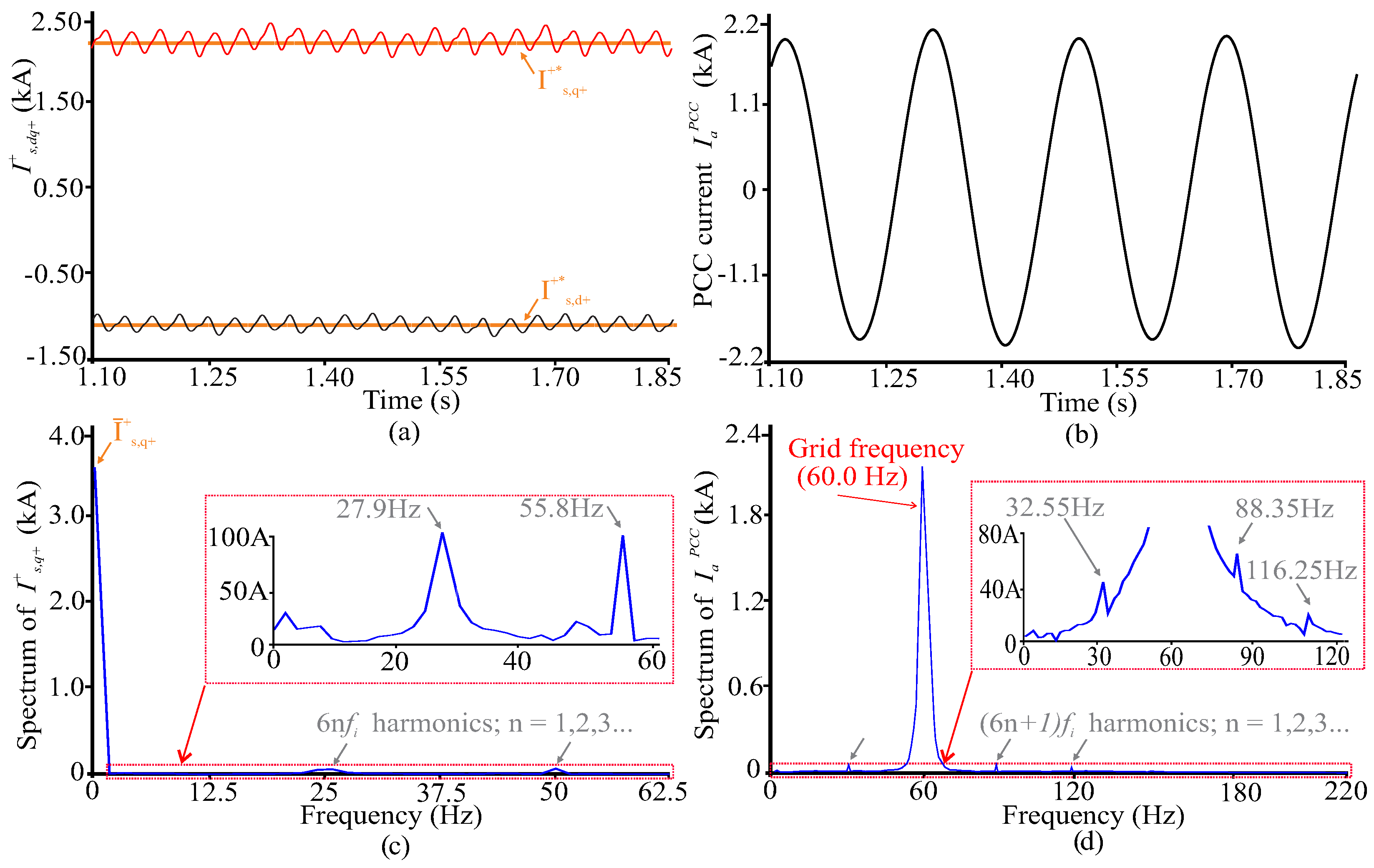
Considering that there is no electrical connection between the EFR and the SCIG, the currents induced in the rotor circuit of the induction generator come from the mechanical vibrations associated with the oscillation of the mechanical torque. The interaction between the rotor flux harmonics and the fundamental grid flux through the air gap induces interharmonic currents in the SCIG stator since these frequencies are multiples of the fundamental frequency of the inverter (). To evaluate the influence of the armature harmonic content due to the PWM inverter voltage and reflected the power generated by the SCIG in the PCC, Figure 6a,b shows the SCIG’s stator currents in and natural reference frame, respectively. Figure 6c,d shows the spectrum of currents and phase a current, respectively. Although the principal impact in spectrum is a dc component, some zero-sequence odd harmonics components are noted, especially the and , with and of amplitude in relation to the level (corresponding the fundamental—), respectively. Similarly, by the inverse Park transformation to the natural frame, some EFR positive sequence harmonic components of are also noticeable at the as pointed out in Figure 6d, as the , , and . However, they also have low magnitudes if compared to the amplitude of the grid frequency (60 Hz) component, with amplitudes of , , and , respectively. Furthermore, the negative sequence harmonic orders () are not present in the natural reference frame spectrum.
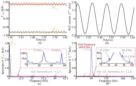
Figure 6.
(a) SCIG stator currents in . (b) Phase a stator current in natural frame. (c) spectrum. (d) Spectrum of phase “a” stator current in natural frame.
4. Test Case 2: Power Quality Indexes and Comparison with a Real Data Extracted of a 2 MW DFIG
The grid side current may affect power quality in the PCC. Therefore, it is great value to identify the most significant harmonic and interharmonic components in different cases, i.e., the operational condition with the maximum harmonic current in the SCIG stator. The standard IEEE 1547-2018 [11] is used as an indication of the good grid-oriented power quality of a DER. Maximum odd and even harmonic current distortion in percent of rated current, interharmonics, and total rated-current distortion (TRD) at the PCC shall not exceed the limits established by the standard. The TRD, which includes the harmonic distortion and inter-harmonic distortion, can be calculated by (38), and is limited to a maximum of 5%,
where represents the root mean square of the DER current, including all frequency components; corresponds to the fundamental current component; and is the DER rated current capacity in the PCC. In addition to this analysis, several simulations in Scilab have been carried out to capture data and compute the TRD of EFR armature phase “a” voltage (), phase “a” EFR armature current (), PCC phase “a” voltage () and PCC phase currents (), considering the associated interval for the interharmonics. In order to sweep the entire turbine output power range, wind speed values between 4 m/s and 11 m/s were assumed. To limit the number of data, only until the fiftieth harmonics are considered.
According to Table 2, the elevated TRD of and at the EFR armature is due to the PWM switching voltage excitation, without interconnection filter, and it has the highest distortion in all different cases for each wind speed. Although this elevated TRD at EFR armature voltages and currents, it has a lower impact on the total distortions of the PCC voltages——and currents—. Besides, the increase in the wind speed decreases the TRD of distortion, which is lower than the [11] limit of for all wind speed operating points.
Table 2.
Relationship between the wind speed (), EFR frequency (), maximum harmonic or interharmonic current in PCC (), dc part of the electromagnetic power (), Total Rated Distortion (TRD-%) of EFR armature, and PCC currents and voltages.
To evaluate the performance of the EFR-driven system, a DFIG was used for comparison as it is widely used in wind farms and derives from the conventional induction machine. The same MW parameters of DFIG with a terminal voltage of V in [32] was used in the EFR simulation for individual and total harmonics comparison, including the connection cable and transformer impedances into the Thevenin equivalent. The total impedance in DFIG system is with short-circuit ratio (SCR) of in PCC, which can be classified as a weak grid. For comparison, to match the results presented in [32], only until the harmonic component of the SCIG and DFIG currents and voltages at the PCC are computed. Figure 7a shows the individual harmonics of the EFR in the percentage of the PCC rated current capacity as the work in [11] also limits the maximum individual odd and even harmonic current distortions. As pointed by FFT analysis in Figure 6d, for wind speed of m/s, the PCC currents have the , , accentuated harmonic components of the EFR armature frequency voltage-, which corresponds to interharmonics related to the fundamental of 60 Hz in SCIG stator. However, these inter-harmonics amplitudes are lower than the maximum allowed by the standard and the (see Figure 7a). In addition, as the goal of the work was to evaluate the EFR performance in the worst scenario, i.e., without passive filters, the resulting harmonics in PCC were mitigated mainly due to the mechanical inertia of the shaft coupling between both machines. Besides that, passive filters can be employed in the inverter output as the LC or LCL topologies proposed in [33,34]. Figure 7b shows the individual current and voltage harmonics components of the grid frequency in the PCC side for both systems. The PCC voltage was computed as a percentage of the rated voltage to put the PCC voltage and current analysis at the same plot. As can be observed in Figure 7b, the EFR driven system is significantly effective in reducing harmonics components than DFIG, especially the components above the harmonic for the current spectrum. The difference between both topologies is even more accentuated in the case of the PCC voltage spectrum, which has almost zero distortion for the SCIG driven by the EFR.
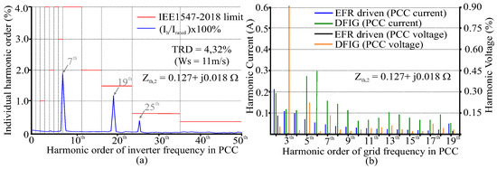
Figure 7.
(a) Individual harmonic order without the fundamental grid component (60 Hz). (b) Individual current and voltage harmonics comparison with DFIG considering the harmonics of the fundamental grid frequency (60 Hz).
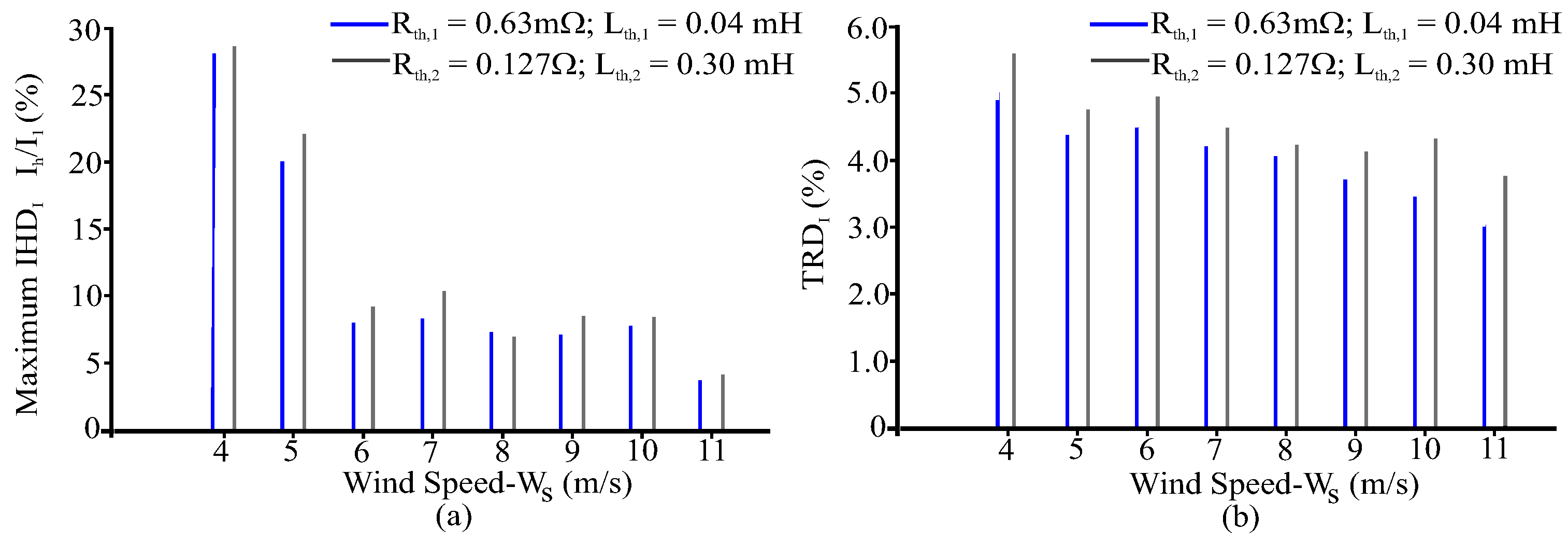
In order to complement the previous analysis, two different ratios of were considered to evaluate the harmonic performance in stator currents of the SCIG under variations in equivalent PCC impedance. Figure 8 shows the results for the maximum Individual Harmonic Distortion (IHD) (a) and the Total Rated Distortion (TRD) (b) for each and . Two types of the grid have been considered in this analysis, including the rated Thevenin equivalent () in Table 1 and the weak grid () in [32]. The results in Figure 8a,b show that for the lowest wind speeds, that is, low power references, the harmonic spectrum is high. That is justified because the fundamental current is low, and its ripple becomes expressive to the amplitude, which contributes to increased harmonic distortion. Besides, in Figure 8b can be seen that the grid parameters have a significant influence on the performance of the TRD, in which the lowest ratio, i.e., , has the poor performance if compared to the highest ratio, i.e., . This fact can be explained by the fact that the inductive reactance becomes greater with increasing frequency, which, in turn, contributes to the mitigation of harmonic components, and the stronger the grid, the lower the effect harmonic emissions [35].
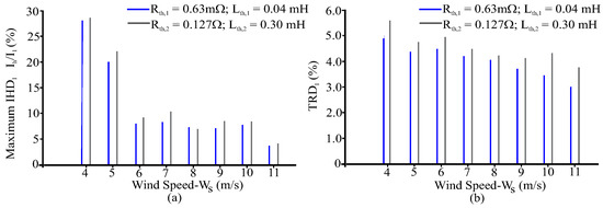
Figure 8.
Distortion analysis versus wind speed () for different grid Thevenin impedances. (a) Maximum Individual Harmonic Distortion (-%). (b) Total Rated Distortion (-%).
5. Conclusions
The power quality issues to regulate the voltage and current distortions are among the most important research topics in wind power systems. The paper’s key contributions are (1) a generic model of the EFR suitable for harmonic, interharmonic, and mechanical disturbances analysis under different operation conditions and (2) analysis of harmonic mitigation of the proposed system based on the limits imposed by the IEEE 1547-2018 standard. Despite the harmonics and inter-harmonics components, it has been shown that the high-frequency components due to the PWM switching are naturally attenuated by the inherent inertia of the mechanical system.
The behavior of the electromagnetic torque mainly dominates the generated power, and the harmonics can affect the behavior of some parts of the mechanical system, which implies the propagation of harmonics generated by the EFR to the SCIG’s stator. The negative and positive sequence harmonic multiples of six caused by the EFR’s armature inverter produce the odd zero-sequence harmonic in the mechanical subsystem, i.e., , , , etc. By analyzing the grid-side current and detecting harmonic frequency with the maximum current in different working conditions, it is found that the interharmonics of EFR-based systems have typical peaks, smoothly reducing with the increase of the active output power. Furthermore, a comparison analysis is performed for the EFR-based system with the limits imposed by the IEEE 1547 standard and real data extracted for DFIG operation in a wind park. The steady-state results show that the EFR-based system has a good power quality performance considering variations of the equivalent grid impedance in the point of common coupling. In summary, the obtained results clearly show the feasibility of using the inherent EFR’s mechanical inertia for mitigate the harmonic impact at the local grid without using extra filters with complex control strategies, as needed in the most conventional machines topologies for wind turbines, such as DFIG and PMSG. This work is a complement of the previous related papers and reinforces the feasibility of using such structure in remote or islanded areas, as the SCIG stator frequency can be driven at the synchronous frequency by the EFR. In addition, the EFR can be used with hybrid energy sources as the integration of photovoltaic to feed the inverter, and with reduced harmonic content originated from the inverter to the local grid. Future work is needed to (1) evaluate the harmonic impact also at the turbine side, as the mechanical perturbations can be propagated through the gearbox, and (2) analyze the impact of unbalances and harmonic distortions of the grid on the performance of EFR and SCIG.
Author Contributions
Conceptualization, M.F.M.J. and T.R.; Data curation, J.C.L.d.S.; Formal analysis, J.C.L.d.S. and M.F.M.J.; Investigation, J.C.L.d.S., T.R. and M.F.M.J.; Methodology, J.C.L.d.S., T.R. and M.F.M.J.; Project administration, M.F.M.J.; Resources, M.F.M.J.; Software, J.C.L.d.S. and T.R.; Supervision, M.F.M.J. and T.R.; Visualization, T.R. and J.C.L.d.S.; Writing—original draft, J.C.L.d.S. All authors have read and agreed to the published version of the manuscript.
Funding
This study was financed in part by the Coordenação de Aperfeiçoamento de Pessoal de Nivel Superior—Brasil (CAPES)—Finance Code 001.
Acknowledgments
The authors acknowledge the Federal Institute of Rio Grande do Norte (IFRN) and the Graduate Program in Electrical Engineering and Computer Science (PPgEC) of the Federal University of Rio Grande do Norte (UFRN) for supporting the development of this work.
Conflicts of Interest
The authors declare no conflict of interest.
Abbreviations
The following abbreviations are used in this manuscript:
| Wind turbine mechanical power | |
| Air density | |
| Turbine blades area | |
| R | Radius of the blade |
| Turbine power coefficient | |
| Wind speed | |
| Tip-speed Ratio | |
| Turbine angular speed | |
| Blade pitch angle | |
| Turbine mechanical torque | |
| EFR armature angular speed | |
| Mechanical torque at the EFR’s armature | |
| Switching frequency | |
| Fundamental frequency of the inverter | |
| Total frequencies resulting of the inverter switching | |
| Grid frequency | |
| PWM reference voltages | |
| Optimized PWM reference voltages | |
| Auxiliary reference voltage | |
| Distribution factor of the optimized PWM modulation | |
| Electrical armature angular speed | |
| Mechanical EFR’s rotor angular speed | |
| Slip angular speed | |
| EFR’s slip | |
| Fundamental positive synchronous reference frame | |
| Voltage in d and q axis in of the EFR’s armature | |
| Voltage in d and q axis in of the EFR’s rotor | |
| Current in d and q axis in of the EFR’s armature | |
| Current in d and q axis in of the EFR’s rotor | |
| Flux in d and q axis in of the EFR’s armature | |
| Flux in d and q axis in of the EFR’s rotor | |
| EFR’s armature resistance | |
| EFR’s rotor resistance | |
| Leakage inductance of EFR’s armature windings | |
| Leakage inductance of EFR’s rotor windings | |
| Maximum mutual inductance between armature and rotor of the EFR windings | |
| Angular speed of the harmonics components in the EFR armature voltage | |
| h | Harmonic order |
| EFR’s harmonic slips | |
| Armature and rotor harmonic components of the EFR in frame | |
| S | Instantaneous three-phase power in the EFR armature |
| Instantaneous EFR three-phase active power in the EFR armature | |
| Instantaneous EFR three-phase reactive power in the EFR armature | |
| Instantaneous EFR three-phase electromagnetic power | |
| Coefficients of the instantaneous EFR three-phase active power | |
| Coefficients of the instantaneous EFR three-phase reactive power | |
| , , , , | Coefficients of the instantaneous three-phase electromagnetic power |
| Electromagnetic torque developed | |
| Mechanical torque at the EFR’s armature | |
| Mechanical torque at the EFR’s rotor | |
| Inertia of the turbine added to the inertia of the rotating armature | |
| Sum of inertia of the EFR’s rotor with the inertia of the SCIG rotor | |
| Rotor friction constant | |
| Turbine friction constant | |
| Electromagnetic torque of reference in the SCIG | |
| Gearbox ratio | |
| Stator synchronous angular frequency | |
| SCIG’s windings resistance | |
| SCIG’s windings reactance | |
| SCIG’s grid phase voltage | |
| SCIG’s magnetizing reactance | |
| reference slip of the SCIG | |
| P | EFR number of pole pairs |
| SCIG number of pole pairs | |
| Armature speed reference | |
| Thevenin impedance of grid 1 and 2, respectively | |
| Thevenin resistance of grid 1 and 2, respectively | |
| Thevenin inductance of grid 1 and 2, respectively | |
| Maximum harmonic or inter-harmonic current in the PCC side | |
| Rated current | |
| Total Rated Distortion including the inter-harmonics | |
| Individual Harmonic Distortion of the variable under analysis | |
| Individual harmonic component of the variable under analysis | |
| Fundamental component of the variable under analysis | |
| EFR armature phase ‘a’ voltage | |
| EFR armature phase ‘a’ current | |
| PCC phase ‘a’ voltage | |
| PCC phase ‘a’ current |
Appendix A
The coefficients , , , , , , , , , , , , and detailed in Section 2.3.1 are calculated by the following equations.
in which,
in which,
References
- Wang, Z.; Anderson, C.L. A Progressive Period Optimal Power Flow for Systems with High Penetration of Variable Renewable Energy Sources. Energies 2021, 14, 2815. [Google Scholar] [CrossRef]
- Pazmiño, I.; Martinez, S.; Ochoa, D. Analysis of Control Strategies Based on Virtual Inertia for the Improvement of Frequency Stability in an Islanded Grid with Wind Generators and Battery Energy Storage Systems. Energies 2021, 14, 698. [Google Scholar] [CrossRef]
- Amin, M.R.; Negnevitsky, M.; Franklin, E.; Alam, K.S.; Naderi, S.B. Application of Battery Energy Storage Systems for Primary Frequency Control in Power Systems with High Renewable Energy Penetration. Energies 2021, 14, 1379. [Google Scholar] [CrossRef]
- Yao, G.; Lu, Z.; Wang, Y.; Benbouzid, M.; Moreau, L. A Virtual Synchronous Generator Based Hierarchical Control Scheme of Distributed Generation Systems. Energies 2017, 10, 2049. [Google Scholar] [CrossRef] [Green Version]
- Lumbreras, D.; Gálvez, E.; Collado, A.; Zaragoza, J. Trends in Power Quality, Harmonic Mitigation and Standards for Light and Heavy Industries: A Review. Energies 2020, 13, 5792. [Google Scholar] [CrossRef]
- Kalmbach, O.; Dirscherl, C.; Hackl, C.M. Discrete-Time DC-Link Voltage and Current Control of a Grid-Connected Inverter with LCL-Filter and Very Small DC-Link Capacitance. Energies 2020, 13, 5613. [Google Scholar] [CrossRef]
- Hoon, Y.; Mohd Radzi, M.A.; Hassan, M.K.; Mailah, N.F. Control Algorithms of Shunt Active Power Filter for Harmonics Mitigation: A Review. Energies 2017, 10, 2038. [Google Scholar] [CrossRef] [Green Version]
- Das, C.K.; Bass, O.; Mahmoud, T.S.; Kothapalli, G.; Mousavi, N.; Habibi, D.; Masoum, M.A. Optimal allocation of distributed energy storage systems to improve performance and power quality of distribution networks. Appl. Energy 2019, 252, 113468. [Google Scholar] [CrossRef]
- García-Sánchez, T.; Muñoz-Benavente, I.; Gómez-Lázaro, E.; Fernández-Guillamón, A. Modelling Types 1 and 2 Wind Turbines Based on IEC 61400-27-1: Transient Response under Voltage Dips. Energies 2020, 13, 4078. [Google Scholar] [CrossRef]
- IEEE Recommended Practice and Requirements for Harmonic Control in Electric Power Systems—Redline. In IEEE Std 519-2014 (Revision of IEEE Std 519-1992)—Redline; IEEE: Piscataway, NJ, USA, 2014; pp. 1–213.
- IEEE Standard for Interconnection and Interoperability of Distributed Energy Resources with Associated Electric Power Systems Interfaces. In IEEE Std 1547-2018 (Revision of IEEE Std 1547-2003); IEEE: Piscataway, NJ, USA, 2018; pp. 1–138. [CrossRef]
- Yao, J.; Li, Q.; Chen, Z.; Liu, A. Coordinated Control of a DFIG-Based Wind-Power Generation System with SGSC under Distorted Grid Voltage Conditions. Energies 2013, 6, 2541–2561. [Google Scholar] [CrossRef]
- Khan, I.; Zeb, K.; Din, W.U.; Islam, S.U.; Ishfaq, M.; Hussain, S.; Kim, H.J. Dynamic Modeling and Robust Controllers Design for Doubly Fed Induction Generator-Based Wind Turbines under Unbalanced Grid Fault Conditions. Energies 2019, 12, 454. [Google Scholar] [CrossRef] [Green Version]
- Hu, J.; Nian, H.; Xu, H.; He, Y. Dynamic Modeling and Improved Control of DFIG Under Distorted Grid Voltage Conditions. IEEE Trans. Energy Convers. 2011, 26, 163–175. [Google Scholar] [CrossRef]
- Pang, B.; Dai, H.; Li, F.; Nian, H. Coordinated Control of RSC and GSC for DFIG System under Harmonically Distorted Grid Considering Inter-Harmonics. Energies 2020, 13, 28. [Google Scholar] [CrossRef] [Green Version]
- Djurović, S.; Williamson, S. Investigation of the impact of speed-ripple and inertia on the steady-state current spectrum of a DFIG with unbalanced rotor. In Proceedings of the 5th IET International Conference on Power Electronics, Machines and Drives (PEMD 2010), Brighton, UK, 19–21 April 2010; pp. 1–6. [Google Scholar] [CrossRef] [Green Version]
- Liao, Y.; Ran, L.; Putrus, G.; Smith, K. Evaluation of the effects of rotor harmonics in a doubly-fed induction generator with harmonic induced speed ripple. IEEE Trans. Energy Convers. 2003, 18, 508–515. [Google Scholar] [CrossRef]
- Xu, H.; Hu, J.; He, Y. Operation of Wind-Turbine-Driven DFIG Systems Under Distorted Grid Voltage Conditions: Analysis and Experimental Validations. IEEE Trans. Power Electron. 2012, 27, 2354–2366. [Google Scholar] [CrossRef]
- Fan, L.; Yuvarajan, S.; Kavasseri, R. Harmonic Analysis of a DFIG for a Wind Energy Conversion System. IEEE Trans. Energy Convers. 2010, 25, 181–190. [Google Scholar] [CrossRef]
- Hernández-Mayoral, E.; Iracheta-Cortez, R.; Lecheppe, V.; Salgado, O.A.J. Modelling and Validation of a Grid-Connected DFIG by Exploiting the Frequency-Domain Harmonic Analysis. Appl. Sci. 2020, 10, 9014. [Google Scholar] [CrossRef]
- Beleiu, H.G.; Maier, V.; Pavel, S.G.; Birou, I.; Pică, C.S.; Dărab, P.C. Harmonics Consequences on Drive Systems with Induction Motor. Appl. Sci. 2020, 10, 1528. [Google Scholar] [CrossRef] [Green Version]
- García, H.; Segundo, J.; Rodríguez-Hernández, O.; Campos-Amezcua, R.; Jaramillo, O. Harmonic Modelling of the Wind Turbine Induction Generator for Dynamic Analysis of Power Quality. Energies 2018, 11, 104. [Google Scholar] [CrossRef] [Green Version]
- Vitor Silva, P.; Ferreira Pinheiro, R.; Ortiz Salazar, A.; Pereira do Santos Junior, L.; Cesar de Azevedo, C. A Proposal for a New Wind Turbine Topology Using an Electromagnetic Frequency Regulator. IEEE Lat. Am. Trans. 2015, 13, 989–997. [Google Scholar] [CrossRef]
- You, R.; Barahona, B.; Chai, J.; Cutululis, N.A. A Novel Wind Turbine Concept Based on an Electromagnetic Coupler and the Study of Its Fault Ride-through Capability. Energies 2013, 6, 6120–6136. [Google Scholar] [CrossRef] [Green Version]
- Ramos, T.; Medeiros Júnior, M.F.; Pinheiro, R.; Medeiros, A. Slip Control of a Squirrel Cage Induction Generator Driven by an Electromagnetic Frequency Regulator to Achieve the Maximum Power Point Tracking. Energies 2019, 12, 2100. [Google Scholar] [CrossRef] [Green Version]
- You, R.; Chai, J.; Sun, X.; Lin, Y. Variable speed wind turbine based on electromagnetic coupler and its experimental measurement. In Proceedings of the IEEE PES General Meeting|Conference & Exposition, National Harbor, MD, USA, 27–31 July 2014; pp. 1–5. [Google Scholar] [CrossRef]
- Patriota, A.S.L.; Pinheiro, R.M.T.G. Harnessing Wind Energy with Hydrostatic Transmission Coupled to an Electromagnetic Frequency Regulator. Preprints 2020, 2020110236. [Google Scholar] [CrossRef]
- Kolesnik, S.; Kuperman, A. Analytical Derivation of Electrical-Side Maximum Power Line for Wind Generators. Energies 2017, 10, 1498. [Google Scholar] [CrossRef] [Green Version]
- Ackermann, T. Wind Power in Power Systems; John Wiley & Sons Ltd.: Chichester, UK, 2005. [Google Scholar]
- Mohan, N.; Undeland, T.M.; Robbins, W.P. Power Electronics: Converters, Applications and Design, 3th ed.; John Wiley & Sons: Hoboken, NJ, USA, 2002; Volume 3. [Google Scholar]
- Jacobina, C.; Nogueira Lima, A.; da Silva, E.; Alves, R.; Seixas, P. Digital scalar pulse-width modulation: A simple approach to introduce nonsinusoidal modulating waveforms. IEEE Trans. Power Electron. 2001, 16, 351–359. [Google Scholar] [CrossRef]
- Liu, Z.; Rong, J.; Zhao, G.; Luo, Y. Harmonic Assessment for Wind Parks Based on Sensitivity Analysis. IEEE Trans. Sustain. Energy 2017, 8, 1373–1382. [Google Scholar] [CrossRef]
- Sanatkar-Chayjani, M.; Monfared, M. Design of LCL and LLCL filters for single-phase grid connected converters. IET Power Electron. 2016, 9, 1971–1978. [Google Scholar] [CrossRef] [Green Version]
- Cittanti, D.; Mandrile, F.; Gregorio, M.; Bojoi, R. Design Space Optimization of a Three-Phase LCL Filter for Electric Vehicle Ultra-Fast Battery Charging. Energies 2021, 14, 1303. [Google Scholar] [CrossRef]
- Kumar, D.; Zare, F. Harmonic Analysis of Grid Connected Power Electronic Systems in Low Voltage Distribution Networks. IEEE J. Emerg. Sel. Top. Power Electron. 2016, 4, 70–79. [Google Scholar] [CrossRef]

Publisher’s Note: MDPI stays neutral with regard to jurisdictional claims in published maps and institutional affiliations. |
© 2021 by the authors. Licensee MDPI, Basel, Switzerland. This article is an open access article distributed under the terms and conditions of the Creative Commons Attribution (CC BY) license (https://creativecommons.org/licenses/by/4.0/).