
Dynamic Modeling of HVDC for Power System Stability Assessment: A Review, Issues, and Recommendations


 , ,
, ,  ,
,
Abstract
:1. Introduction
- The model of HVDC models developed with VSC application and their precise control strategies with numerous characteristics are explained in Table 2. Various kinds of computational models for the simulation of VSC are described with their applicability as it is the building block of future grids.
- In this paper, distinguished levels of dynamic HVDC models are explained thoroughly to deliver a reliable stability estimation in complex mixed AC or DC systems. This exhibits the trade-off between the correctness of dynamic responses and the complexity of the HVDC dynamic models.
- Various control models have been studied in both single and multi-infeed including LCC-HVDC and MMC-MTDC highlighting the execution process, strengths, and weaknesses. Nevertheless, there are some methodological difficulties while implementing the MMC to DC transmission system.
- Existing issues and limitations of HVDC modeling with regard to inverter, reactive power, frequency, harmonics, and switching issues are highlighted.
- Based on existing constraints, future recommendations are provided for the development of advanced HVDC modeling as well as further investigation of HVDC preference in different levels of power and voltage applications.
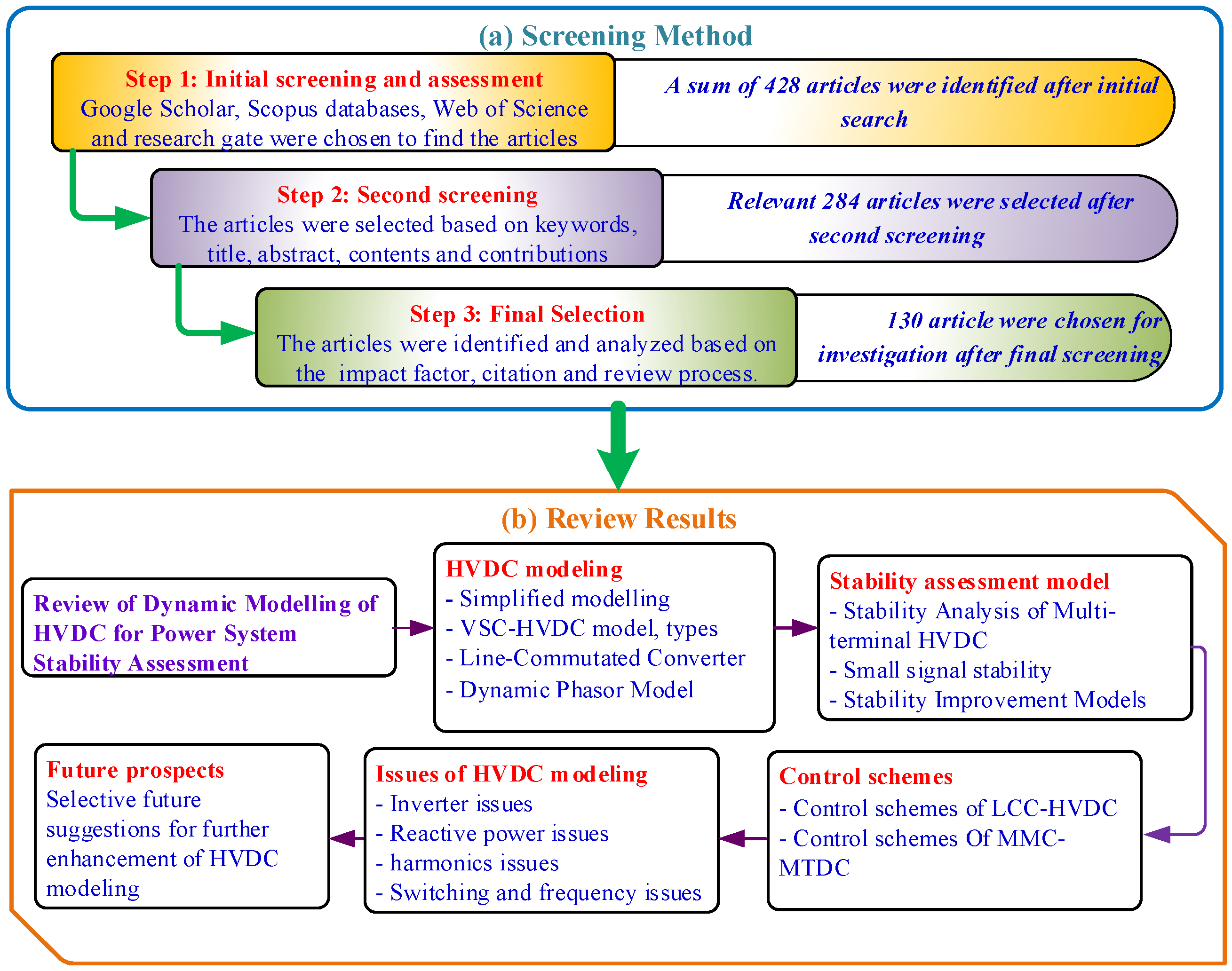
2. Reviewing Methodology
3. Overview of Modeling of HVDC System
3.1. Simplified Modeling of HVDC Systems
3.2. Dynamic AVM of HVDC Systems
- Mathematical modeling of VSC HVDC
- Types of VSC HVDC Models
- Control Strategies Of LCC-HVDC Systems
3.3. Dynamic Phasor Model of HVDC System
4. Stability Assessment Models in HVDC
4.1. Control Strategies of MMC-MTDC
- (a)
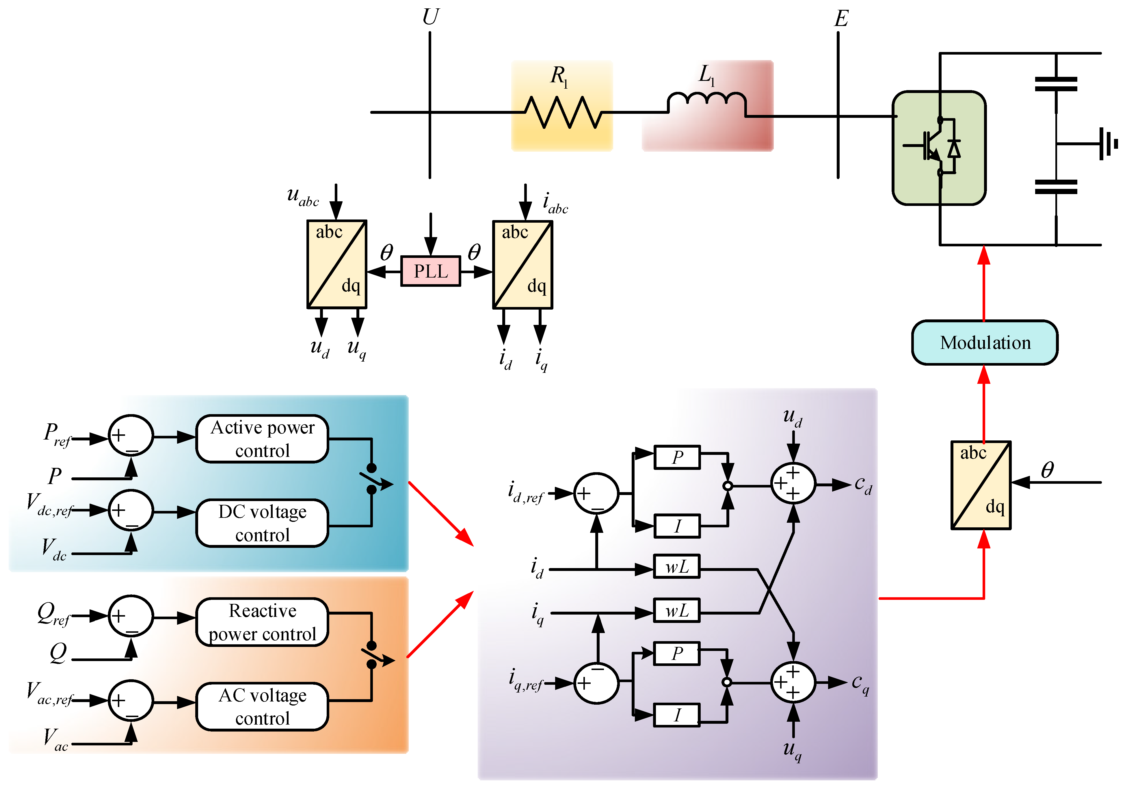
- DC Voltage Control—the commonly used control architecture of a VSC in the MTDC systems is shown in Figure 12, which consists of inner and outer control loops [87]. This control scheme is also applicable to the MMC-based converter station. The DC voltage control is implemented through the outer control loop. Unlike the frequency of the AC system as a global control parameter, the DC voltage varies in the DC grid due to the power flow regulated among bus voltages of the DC network [88]. Currently, there are three primary methods for DC voltage control: Voltage margin control, master–slave control, and voltage droop control [89,90].
- (b)
- Power flow—the power flow and sharing of the VSC-MTDC systems is controlled by the DC voltage of each terminal, as shown in Figure 13 [87]. It is essential to consider the stability region, the limitation, and the optimal parameter determination of voltage control approaches to calculate the power flow and sharing. In [91], a power-sharing control strategy and DC voltage are introduced based on a combination of an optimal DC power flow algorithm and a voltage-droop method for the most effective execution of the MTDC grids. Work by [73] proposes an improved analytic model for the steady-state analysis of droop-controlled VSC-MTDC operations. The authors in [92] suggested a generalized algorithm to solve the DC-power flow of the MTDC operations with various nonlinear voltage droops.
- (c)
- Power Oscillation Damping—MTDC systems can also allow further control functions to develop system dynamic execution, such as transient stability and fault recovery [25], power oscillation damping [93], and sub-synchronous damping improvement [94]. The occurrence of low-frequency inter-area power oscillations is common in energy systems [95], which has resulted in some extensive-scale blackouts [96]. The inner-vicinity oscillation is one of the central causes of power system failure [97,98,99]. The damper windings of the synchronous machines, as well as digital electro-hydro structures without global signal computation, can reduce the inner-vicinity oscillations efficiently [68,100]. Thus, the attenuation of the inner-area power oscillations is important and has remained a challenge for a long time. Table 4 lists the details of some multi-terminal HVDC projects.
4.2. Small Signal Stability
4.3. Stability Improvement Models
5. Issues and Challenges
- When the obstruction in DC energy transfer takes place, reactive power consumption through the converter will fall to 0. Therefore, the AC voltage might be developed because of the shunt capacitor and harmonic filter. These phenomena can demand excessive insulation of material within the operation, otherwise this material could probably be destroyed due to the overvoltage [108,121].
- Since harmonics are produced by the converter current at the AC link as well as the converter voltage at the DC link, harmonics generated through the DC side are enhanced whilst the DC energy release is improved [124]. Having said that, the energy transfer between AC and DC within the converter produces unusual harmonics although the pulse firing system is under control. It becomes a more serious issue when those unrepresentative harmonics damage the resonant networks, causing the operating status of the HV DC/AC operation to become complex [125,126]. The moderate harmonic resonance at the AC link would possibly generate further due to the DC link series resonance on the primary frequency, leading to critical difficulties [127,128].
- Due to the switching among the shunt capacitor, the shunt reactor is rapidly under varying load conditions, and voltage variations may appear, which result in AC voltage flicker [129]. Moreover, voltage flicker takes place due to the inner harmonic generation through the change in loads. The influence of inner harmonics is more complex than harmonics. The inner harmonics frequencies are not integer multiples of the primary frequency, and the value of the voltage waveform would possibly swing even within the position of waveform distortions [130].
6. Conclusions and Recommendations
- The VSC-HVDC has synchronization issues while connected to a vulnerable AC system. Aside from interfacing with a limited AC operation, the VSC-HVDC-based adaptive backstepping controller is applied to handle voltage droop in the offshore wind farm. The adaptive back-stepping controller is employed to decrease the voltage rise as well as the minimal voltage drop at some point of a fault situation, leading to an improvement in voltage output with the diminished settling period. To address the aforesaid concerns, a PI controller and a fuzzy controller can be employed to stabilize the network operation.
- The selection of appropriate controller parameters is crucial to enhance the stability performance of the VSC-HVDC transmission system. Hence, the different optimization algorithms can be integrated with controllers such as PI and fuzzy logic. Nevertheless, the inclusion of optimization may increase the installation cost as well as commutation loss. Since the operation of VSC is constrained under limited voltage and power levels, further studies are required on VSC-HVDC under different levels of voltage and power.
- The very specific DC operations still pose various severe restrictions to the scope of the network. Thus, the advancement of hybrid models can be suggested including a complete EMT design of the DC operation and the AC operation within the era of the converter, connected to a preferred electromechanical version for the remainder of the AC system. Such connected methods are in a situation of continuous study and will operate an influential part of incoming energy system modeling for dynamic AC/DC operation.
- For large-scale power systems, further effective models need to be improved with active simulation acceleration. Nevertheless, the models are required to simulate state variables correctly with a small-time step under dynamic responses leading to a high computational load. Consequently, there is a tradeoff between precision and effectiveness. The future control strategy of the MMC-MTDC systems can be developed using droop control to improve the performance in both AC and DC structures by addressing the converter outages and power oscillations. Multi-functional control configurations could assure an effective control plan of the MMC-MTDC systems.
- The abovementioned recommendations could play remarkable roles in developing and executing advanced HVDC models. Moreover, the information and analysis of this review can deliver a clear idea and information to power system engineers and researchers on the HVDC model structure, assessment models, and control schemes. Overall, this review helps to pave a pathway for future sustainable power transmission systems.
Author Contributions
Funding
Conflicts of Interest
References
- Hannan, M.A.; Hussin, I.; Ker, P.J.; Hoque, M.M.; Hossain Lipu, M.S.; Hussain, A.; Rahman, M.S.A.; Faizal, C.W.M.; Blaabjerg, F. Advanced control strategies of VSC Based HVDC transmission system: Issues and potential recommendations. IEEE Access 2018, 6, 78352–78369. [Google Scholar] [CrossRef]
- Alassi, A.; Bañales, S.; Ellabban, O.; Adam, G.; MacIver, C. HVDC Transmission: Technology Review, Market Trends and Future Outlook. Renew. Sustain. Energy Rev. 2019, 112, 530–554. [Google Scholar] [CrossRef]
- Pierri, E.; Binder, O.; Hemdan, N.G.A.; Kurrat, M. Challenges and opportunities for a European HVDC grid. Renew. Sustain. Energy Rev. 2017, 70, 427–456. [Google Scholar] [CrossRef]
- Benasla, M.; Allaoui, T.; Brahami, M.; Denaï, M.; Sood, V.K. HVDC links between North Africa and Europe: Impacts and benefits on the dynamic performance of the European system. Renew. Sustain. Energy Rev. 2018, 82, 3981–3991. [Google Scholar] [CrossRef] [Green Version]
- Tosatto, A.; Weckesser, T.; Chatzivasileiadis, S. Market Integration of HVDC Lines: Internalizing HVDC Losses in Market Clearing. IEEE Trans. Power Syst. 2020, 35, 451–461. [Google Scholar] [CrossRef] [Green Version]
- Xiao, H.; Sun, K.; Pan, J.; Li, Y.; Liu, Y. Review of hybrid HVDC systems combining line communicated converter and voltage source converter. Int. J. Electr. Power Energy Syst. 2021, 129, 106713. [Google Scholar] [CrossRef]
- Semeraro, M.A. Renewable energy transport via hydrogen pipelines and HVDC transmission lines. Energy Strategy Rev. 2021, 35, 100658. [Google Scholar] [CrossRef]
- Khazaei, J.; Idowu, P.; Asrari, A.; Shafaye, A.; Piyasinghe, L. Review of HVDC control in weak AC grids. Electr. Power Syst. Res. 2018, 162, 194–206. [Google Scholar] [CrossRef]
- Kamari, N.A.M.; Musirin, I.; Ibrahim, A.A.; Halim, S.A. Intelligent swarm-based optimization technique for oscillatory stability assessment in power system. IAES Int. J. Artif. Intell. 2019, 8, 342–351. [Google Scholar] [CrossRef]
- Briff, P.; Chivite-Zabalza, J.; Nicholls, J.; Vershinin, K. Turn-Off Delay Compensation of Series-Connected IGBTs for HVDC Applications. IEEE Trans. Power Electron. 2020, 35, 11294–11298. [Google Scholar] [CrossRef]
- Islam, N.N.; Hannan, M.A.; Shareef, H.; Mohamed, A. An application of backtracking search algorithm in designing power system stabilizers for large multi-machine system. Neurocomputing 2017, 237, 175–184. [Google Scholar] [CrossRef]
- Li, R.; Yu, L.; Xu, L.; Adam, G.P. Coordinated Control of Parallel DR-HVDC and MMC-HVDC Systems for Offshore Wind Energy Transmission. IEEE J. Emerg. Sel. Top. Power Electron. 2020, 8, 2572–2582. [Google Scholar] [CrossRef]
- Sun, P.; Wickramasinghe, H.R.; Konstantinou, G. Hybrid LCC-AAC HVDC transmission system. Electr. Power Syst. Res. 2021, 192, 106910. [Google Scholar] [CrossRef]
- Haleem, N.M.; Rajapakse, A.D.; Gole, A.M.; Fernando, I.T. Investigation of Fault Ride-Through Capability of Hybrid VSC-LCC Multi-Terminal HVDC Transmission Systems. IEEE Trans. Power Deliv. 2019, 34, 241–250. [Google Scholar] [CrossRef]
- Silva, K.M.; Tavares, J.J.C.; Ribeiro, N.S.S.; Lopes, F.V. Impact of DFT-Based phasor estimation errors due to commutation failures of LCC-HVDC links on the protection of AC lines in the near vicinity. Electr. Power Syst. Res. 2021, 196, 107287. [Google Scholar] [CrossRef]
- Song, J.; Li, Y.; Zhang, Y. Fault steady-state analysis method for the AC system with LCC-HVDC infeed. Electr. Power Syst. Res. 2021, 192, 106994. [Google Scholar] [CrossRef]
- Raza, A.; Yousaf, Z.; Jamil, M.; Gilani, S.O.; Abbas, G.; Uzair, M.; Shaheen, S.; Benrabah, A.; Li, F. Multi-Objective Optimization of VSC Stations in Multi-Terminal VSC-HVdc Grids, Based on PSO. IEEE Access 2018, 6, 62995–63004. [Google Scholar] [CrossRef]
- Adewolu, B.O.; Saha, A.K. Contingency Control Capability of an Optimized HVDC-based VSC Transmission System. IEEE Access 2020, 9, 4112–4128. [Google Scholar] [CrossRef]
- Guo, C.; Zhao, C.; Iravani, R.; Ding, H.; Wang, X. Impact of phase-locked loop on small-signal dynamics of the line commutated converter-based high-voltage direct-current station. IET Gener. Transm. Distrib. 2017, 11, 1311–1318. [Google Scholar] [CrossRef]
- Zou, C.; Rao, H.; Xu, S.; Li, Y.; Li, W.; Chen, J.; Zhao, X.; Yang, Y.; Lei, B. Analysis of Resonance between a VSC-HVDC Converter and the AC Grid. IEEE Trans. Power Electron. 2018, 33, 10157–10168. [Google Scholar] [CrossRef]
- Wang, Y.; Zhao, C.; Guo, C. Comparison study of small-signal stability of MMC-HVDC system in different control modes. Int. J. Electr. Power Energy Syst. 2019, 111, 425–435. [Google Scholar] [CrossRef]
- Daryabak, M.; Filizadeh, S.; Jatskevich, J.; Davoudi, A.; Saeedifard, M.; Sood, V.K.; Martinez, J.A.; Aliprantis, D.; Cano, J.; Mehrizi-Sani, A. Modeling of LCC-HVDC systems using dynamic phasors. IEEE Trans. Power Deliv. 2014, 29, 1989–1998. [Google Scholar] [CrossRef]
- Annakkage, U.D.; Karawita, C.; Arunprasanth, S.; Konara, H. Dynamic phasor modeling of HVDC systems. In Modeling and Simulation of HVDC Transmission; Institution of Engineering and Technology (IET): London, UK, 2020; pp. 213–243. [Google Scholar]
- Debnath, S.; Qin, J.; Bahrani, B.; Saeedifard, M.; Barbosa, P. Operation, control, and applications of the modular multilevel converter: A review. IEEE Trans. Power Electron. 2015, 30, 37–53. [Google Scholar] [CrossRef]
- Liu, L.; Liu, C. VSCs-HVDC may improve the Electrical Grid Architecture in future world. Renew. Sustain. Energy Rev. 2016, 62, 1162–1170. [Google Scholar] [CrossRef]
- Hong, L.; Zhou, X.; Xia, H.; Liu, Y.; Luo, A. Mechanism and prevention of commutation failure in LCC-HVDC caused by sending end AC faults. IEEE Trans. Power Deliv. 2021, 36, 473–476. [Google Scholar] [CrossRef]
- Xiao, H.; Li, Y.; Lan, T. Sending End AC Faults can Cause Commutation Failure in LCC-HVDC Inverters. IEEE Trans. Power Deliv. 2020, 35, 2554–2557. [Google Scholar] [CrossRef]
- Xue, Y.; Zhang, X.-P.; Yang, C. Commutation Failure Elimination of LCC HVDC Systems Using Thyristor-Based Controllable Capacitors. IEEE Trans. Power Deliv. 2018, 33, 1448–1458. [Google Scholar] [CrossRef]
- Xue, Y.; Zhang, X.-P.; Yang, C. AC Filterless Flexible LCC HVDC With Reduced Voltage Rating of Controllable Capacitors. IEEE Trans. Power Syst. 2018, 33, 5507–5518. [Google Scholar] [CrossRef]
- Mitra, P.; Zhang, L.; Harnefors, L. Offshore Wind Integration to a Weak Grid by VSC-HVDC Links Using Power-Synchronization Control: A Case Study. IEEE Trans. Power Deliv. 2014, 29, 453–461. [Google Scholar] [CrossRef]
- Huang, L.; Xin, H.; Yang, H.; Wang, Z.; Xie, H. Interconnecting Very Weak AC Systems by Multiterminal VSC-HVDC Links with a Unified Virtual Synchronous Control. IEEE J. Emerg. Sel. Top. Power Electron. 2018, 6, 1041–1053. [Google Scholar] [CrossRef]
- Ndreko, M.; Rueda, J.L.; Popov, M.; van der Meijden, M.A.M.M. Optimal fault ride through compliance of offshore wind power plants with VSC-HVDC connection by meta-heuristic based tuning. Electr. Power Syst. Res. 2017, 145, 99–111. [Google Scholar] [CrossRef]
- Cigré, W.G. Guide for the Development of Models for HVDC Converters in a HVDC Grid; CIGRE: Paris, France, 2014; ISBN 9782858733057. [Google Scholar]
- Antonopoulos, A.; Angquist, L.; Nee, H.-P. On dynamics and voltage control of the Modular Multilevel Converter. In Proceedings of the 13th European Conference on Power Electronics and Applications, Barcelona, Spain, 8–10 September 2009; pp. 1–5. [Google Scholar]
- Jacobson, B.; Karlsson, P.; Asplund, G.; Harnefors, L.; Jonsson, T. VSC-HVDC Transmission with Cascaded Two-Level Converters. In Proceedings of the CIGRE Technical Exhibition: The Prestigious Event in the World of HV, Paris, France, 22–27 August 2010; B4–110. pp. 1–8. [Google Scholar]
- De Toledo Silva, F.A.; Komatsu, W.; Jardini, J.A. Use of DC/DC converters modeled as AC-DC converters in HVDC Grids. In Proceedings of the IEEE PES Transmission and Distribution Conference and Exhibition, Montevideo, Uruguay, 28 September–2 October 2020; pp. 1–6. [Google Scholar]
- Peralta, J.; Saad, H.; Dennetière, S.; Mahseredjian, J.; Nguefeu, S. Detailed and averaged models for a 401-level MMC-HVDC system. IEEE Trans. Power Deliv. 2012, 27, 1501–1508. [Google Scholar] [CrossRef]
- Oleka, E.U.; Ndubisi, S.N.; Ijemaru, G.K. Electric Power Transmission Enhancement: A Case of Nigerian Electric Power Grid. Am. J. Electr. Electron. Eng. 2016, 4, 33–39. [Google Scholar]
- Sood, V.K. HVDC and FACTS Controllers—Applications of Static Converters in Power Systems; Springer: Cham, Switzerland, 2004. [Google Scholar]
- Eremia, M.; Liu, C.C.; Edris, A.A. Advanced Solutions in Power Systems: HVDC, FACTS, and AI Techniques; Wiley-IEEE Press: Piscataway, NJ, USA, 2016; ISBN 9781119175391. [Google Scholar]
- Karaolanis, A.; Perilla Guerra, A.; Rueda Torres, J.L.; van der Meijden, M.A.A.M.; Alefragkis, A. Generic model of a VSC-based HVDC link for RMS simulations in PSS/E. IFAC-PapersOnLine 2018, 51, 303–308. [Google Scholar] [CrossRef]
- Dragan, J. High Voltage Direct Current Transmission: Converters, Systems and DC Grids; Wiley: Piscataway, NJ, USA, 2015. [Google Scholar]
- Wang, D.; Fu, J.; Hou, M.; Qiao, F.; Gao, M. Novel travelling wave fault location principle for VSC-HVDC transmission line. Electr. Power Syst. Res. 2021, 196, 107226. [Google Scholar] [CrossRef]
- Li, C.; Cao, Y.; Yang, Y.; Wang, L.; Blaabjerg, F.; Dragicevic, T. Impedance-based method for DC stability of VSC-HVDC system with VSG control. Int. J. Electr. Power Energy Syst. 2021, 130, 106975. [Google Scholar] [CrossRef]
- Li, B.; Wang, W.; Liu, Y.; Li, B.; Wen, W. Research on power flow calculation method of true bipolar VSC-HVDC grids with different operation modes and control strategies. Int. J. Electr. Power Energy Syst. 2021, 126, 106558. [Google Scholar] [CrossRef]
- Li, B.; Mao, Q.; He, J.; Li, Y.; Wu, T.; Dai, W.; Li, X.; Yu, Q. Adaptive reclosing strategy for the mechanical DC circuit breaker in VSC-HVDC grid. Electr. Power Syst. Res. 2021, 192, 107008. [Google Scholar] [CrossRef]
- Sima, W.; Fu, Z.; Yang, M.; Yuan, T.; Sun, P.; Han, X.; Si, Y. A Novel Active Mechanical HVDC Breaker with Consecutive Interruption Capability for Fault Clearances in MMC-HVDC Systems. IEEE Trans. Ind. Electron. 2019, 66, 6979–6989. [Google Scholar] [CrossRef]
- Man, J.; Xie, X.; Xu, S.; Zou, C.; Yin, C. Frequency-Coupling Impedance Model Based Analysis of a High-Frequency Resonance Incident in an Actual MMC-HVDC System. IEEE Trans. Power Deliv. 2020, 35, 2963–2971. [Google Scholar] [CrossRef]
- Harnefors, L.; Finger, R.; Wang, X.; Bai, H.; Blaabjerg, F. VSC Input-Admittance Modeling and Analysis above the Nyquist Frequency for Passivity-Based Stability Assessment. IEEE Trans. Ind. Electron. 2017, 64, 6362–6370. [Google Scholar] [CrossRef]
- Shinoda, K.; Benchaib, A.; Dai, J.; Guillaud, X. DC voltage control of MMC-based HVDC grid with Virtual Capacitor Control. In Proceedings of the European Conference on Power Electronics and Applications, Warsaw, Poland, 11–14 September 2017; pp. 1–10. [Google Scholar]
- Atighechi, H.; Chiniforoosh, S.; Jatskevich, J.; Davoudi, A.; Martinez, J.A.; Faruque, M.O.; Sood, V.; Saeedifard, M.; Cano, J.M.; Mahseredjian, J.; et al. Dynamic average-value modeling of CIGRE HVDC benchmark system. IEEE Trans. Power Deliv. 2014, 29, 2046–2054. [Google Scholar] [CrossRef]
- Pegueroles, J.; Barnes, M.; Gomis, O.; Beddard, A.; Bianchi, F.D. Modelling and analysis of CIGRE HVDC offshore multi-terminal benchmark grid. Energy Procedia 2015, 80, 72–82. [Google Scholar] [CrossRef] [Green Version]
- Beddard, A.; Barnes, M. Modelling of MMC-HVDC systems—An overview. Energy Procedia 2015, 80, 201–212. [Google Scholar] [CrossRef]
- Beddard, A.; Barnes, M.; Preece, R. Comparison of Detailed Modeling Techniques for MMC Employed on VSC-HVDC Schemes. IEEE Trans. Power Deliv. 2015, 30, 579–589. [Google Scholar] [CrossRef]
- Zhang, L.; Harnefors, L.; Nee, H.P. Modeling and control of VSC-HVDC links connected to island systems. IEEE Trans. Power Syst. 2011, 26, 783–793. [Google Scholar] [CrossRef]
- Xu, T.; Donoghue, M.W.; Davidson, C.C. IGBT overcurrent turn-off tests for the MMC-based VSC valves. In Proceedings of the European Conference on Power Electronics and Applications, Lille, France, 2–6 September 2013; pp. 1–6. [Google Scholar]
- Saad, H.; Peralta, J.; Dennetiere, S.; Mahseredjian, J.; Jatskevich, J.; Martinez, J.A.; Davoudi, A.; Saeedifard, M.; Sood, V.; Wang, X.; et al. Dynamic Averaged and Simplified Models for MMC-Based HVDC Transmission Systems. IEEE Trans. Power Deliv. 2013, 28, 1723–1730. [Google Scholar] [CrossRef]
- Gnanarathna, U.N.; Gole, A.M.; Jayasinghe, R.P. Efficient modeling of modular multilevel HVDC converters (MMC) on electromagnetic transient simulation programs. IEEE Trans. Power Deliv. 2011, 26, 316–324. [Google Scholar] [CrossRef] [Green Version]
- Khan, S.; Bhowmick, S. A novel power-flow model of multi-terminal VSC-HVDC systems. Electr. Power Syst. Res. 2016, 133, 219–227. [Google Scholar] [CrossRef]
- Khan, S.; Bhowmick, S. Generalized power flow models for VSC based multi-terminal HVDC systems. Int. J. Electr. Power Energy Syst. 2016, 82, 67–75. [Google Scholar] [CrossRef]
- Filizadeh, S.; Gole, A.M.; Woodford, D.A.; Irwin, G.D. An optimization-enabled electromagnetic transient simulation-based methodology for HVDC controller design. IEEE Trans. Power Deliv. 2007, 22, 2559–2566. [Google Scholar] [CrossRef]
- Niamul Islam, N.; Hannan, M.A.; Mohamed, A.; Shareef, H. Improved Power System Stability Using Backtracking Search Algorithm for Coordination Design of PSS and TCSC Damping Controller. PLoS ONE 2016, 11, e0146277. [Google Scholar] [CrossRef]
- Luo, S.; Dong, X.; Shi, S.; Wang, B. A Directional Protection Scheme for HVDC Transmission Lines Based on Reactive Energy. IEEE Trans. Power Deliv. 2016, 31, 559–567. [Google Scholar] [CrossRef]
- Li, Y.; Luo, L.; Rehtanz, C.; Rüberg, S.; Liu, F. Realization of Reactive Power Compensation Near the LCC-HVDC Converter Bridges by Means of an Inductive Filtering Method. IEEE Trans. Power Electron. 2012, 27, 3908–3923. [Google Scholar] [CrossRef]
- Pradhan, J.K.; Ghosh, A.; Bhende, C.N. Small-signal modeling and multivariable PI control design of VSC-HVDC transmission link. Electr. Power Syst. Res. 2017, 144, 115–126. [Google Scholar] [CrossRef]
- Harnefors, L.; Wang, X.; Yepes, A.G.; Blaabjerg, F. Passivity-based stability assessment of grid-connected VSCs—An overview. IEEE J. Emerg. Sel. Top. Power Electron. 2015, 4, 116–125. [Google Scholar] [CrossRef] [Green Version]
- Guo, C.; Liu, W.; Zhao, C.; Iravani, R. A Frequency-Based Synchronization Approach for the VSC-HVDC Station Connected to a Weak AC Grid. IEEE Trans. Power Deliv. 2017, 32, 1460–1470. [Google Scholar] [CrossRef]
- Hannan, M.A.; Islam, N.N.; Mohamed, A.; Lipu, M.S.H.; Ker, P.J.; Rashid, M.M.; Shareef, H. Artificial Intelligent Based Damping Controller Optimization for the Multi-Machine Power System: A Review. IEEE Access 2018, 6, 39574–39594. [Google Scholar] [CrossRef]
- Nanou, S.I.; Papathanassiou, S.A. Grid Code Compatibility of VSC-HVDC Connected Offshore Wind Turbines Employing Power Synchronization Control. IEEE Trans. Power Syst. 2016, 31, 5042–5050. [Google Scholar] [CrossRef]
- Zhang, L.; Harnefors, L.; Nee, H.-P. Power-Synchronization Control of Grid-Connected Voltage-Source Converters. IEEE Trans. Power Syst. 2010, 25, 809–820. [Google Scholar] [CrossRef]
- Bergna, G.; Garces, A.; Berne, E.; Egrot, P.; Arzande, A.; Vannier, J.C.; Molinas, M. A generalized power control approach in ABC frame for modular multilevel converter HVDC links based on mathematical optimization. IEEE Trans. Power Deliv. 2014, 29, 386–394. [Google Scholar] [CrossRef] [Green Version]
- Xiang, W.; Lin, W.; An, T.; Wen, J.; Wu, Y. Equivalent Electromagnetic Transient Simulation Model and Fast Recovery Control of Overhead VSC-HVDC Based on SB-MMC. IEEE Trans. Power Deliv. 2017, 32, 778–788. [Google Scholar] [CrossRef]
- Xiao, L.; Xu, Z.; An, T.; Bian, Z. Improved Analytical Model for the Study of Steady State Performance of Droop-Controlled VSC-MTDC Systems. IEEE Trans. Power Syst. 2017, 32, 2083–2093. [Google Scholar] [CrossRef]
- Prieto-Araujo, E.; Bianchi, F.D.; Junyent-Ferre, A.; Gomis-Bellmunt, O. Methodology for Droop Control Dynamic Analysis of Multiterminal VSC-HVDC Grids for Offshore Wind Farms. IEEE Trans. Power Deliv. 2011, 26, 2476–2485. [Google Scholar] [CrossRef]
- Mahela, O.P.; Shaik, A.G. Comprehensive overview of grid interfaced wind energy generation systems. Renew. Sustain. Energy Rev. 2016, 57, 260–281. [Google Scholar] [CrossRef]
- Lee, C.H.; Chung, B.R. Adaptive backstepping controller design for nonlinear uncertain systems using fuzzy neural systems. Int. J. Syst. Sci. 2012, 43, 1855–1869. [Google Scholar] [CrossRef]
- Huang, J.; Xu, D.; Yan, W.; Ge, L.; Yuan, X. Nonlinear Control of Back-to-Back VSC-HVDC System via Command-Filter Backstepping. J. Control Sci. Eng. 2017, 2017, 1–10. [Google Scholar] [CrossRef]
- Liu, Y.; Chen, Z. A Flexible Power Control Method of VSC-HVDC Link for the Enhancement of Effective Short-Circuit Ratio in a Hybrid Multi-Infeed HVDC System. IEEE Trans. Power Syst. 2013, 28, 1568–1581. [Google Scholar] [CrossRef]
- Mc Namara, P.; Negenborn, R.R.; De Schutter, B.; Lightbody, G. Optimal Coordination of a Multiple HVDC Link System Using Centralized and Distributed Control. IEEE Trans. Control Syst. Technol. 2013, 21, 302–314. [Google Scholar] [CrossRef]
- Liu, J.; Tai, N.; Fan, C. Transient-Voltage-Based Protection Scheme for DC Line Faults in the Multiterminal VSC-HVDC System. IEEE Trans. Power Deliv. 2017, 32, 1483–1494. [Google Scholar] [CrossRef]
- Schönleber, K.; Collados, C.; Pinto, R.T.; Ratés-Palau, S.; Gomis-Bellmunt, O. Optimization-based reactive power control in HVDC-connected wind power plants. Renew. Energy 2017, 109, 500–509. [Google Scholar] [CrossRef] [Green Version]
- Hannan, M.A.; Lipu, M.S.H.; Ker, P.J.; Begum, R.A.; Agelidis, V.G.; Blaabjerg, F. Power electronics contribution to renewable energy conversion addressing emission reduction: Applications, issues, and recommendations. Appl. Energy 2019, 251, 113404. [Google Scholar] [CrossRef]
- Guo, M.; Li, X.; Gao, Z.; Su, G. Simulation and Analysis on Stability Improvement of Zhangbei Renewable Energy Transmission via VSC-HVDC Based on RTDS. In Proceedings of the International Conference on HVDC, Xi’an, China, 6–9 November 2020; pp. 299–303. [Google Scholar]
- System, M.; Wang, Y.; Zhao, C.; Member, S.; Guo, C.; Member, S.; Rehman, A.U. Dynamic modeling and small signal stability analysis of PMSG-based wind farm with MMC-HVDC system. CSEE J. Power Energy Syst. 2019, 6, 226–235. [Google Scholar]
- Gavriluta, C.; Candela, J.I.; Rocabert, J.; Luna, A.; Rodriguez, P. Adaptive droop for control of multiterminal DC bus integrating energy storage. IEEE Trans. Power Deliv. 2015, 30, 16–24. [Google Scholar] [CrossRef] [Green Version]
- Gavriluta, C.; Candela, I.; Luna, A.; Gomez-Exposito, A.; Rodriguez, P. Hierarchical Control of HV-MTDC Systems With Droop-Based Primary and OPF-Based Secondary. IEEE Trans. Smart Grid 2015, 6, 1502–1510. [Google Scholar] [CrossRef]
- Zhang, L.; Zou, Y.; Yu, J.; Qin, J.; Vijay, V.; Karady, G.G.; Shi, D.; Wang, Z. Modeling, control, and protection of modular multilevel converter-based multi-terminal HVDC systems: A review. CSEE J. Power Energy Syst. 2017, 3, 340–352. [Google Scholar] [CrossRef]
- Rouzbehi, K.; Miranian, A.; Candela, J.I.; Luna, A.; Rodriguez, P. A generalized voltage droop strategy for control of multiterminal DC grids. IEEE Trans. Ind. Appl. 2015, 51, 607–618. [Google Scholar] [CrossRef]
- Chen, X.; Wang, L.; Sun, H.; Chen, Y. Fuzzy Logic Based Adaptive Droop Control in Multiterminal HVDC for Wind Power Integration. IEEE Trans. Energy Convers. 2017, 32, 1200–1208. [Google Scholar] [CrossRef]
- Haileselassie, T.M.; Uhlen, K. Impact of DC line voltage drops on power flow of MTDC using droop control. IEEE Trans. Power Syst. 2012, 27, 1441–1449. [Google Scholar] [CrossRef]
- Rouzbehi, K.; Miranian, A.; Luna, A.; Rodriguez, P. DC voltage control and power sharing in multiterminal DC grids based on optimal DC power flow and voltage-droop strategy. IEEE J. Emerg. Sel. Top. Power Electron. 2014, 2, 1171–1180. [Google Scholar] [CrossRef]
- Wang, W.; Barnes, M. Power flow algorithms for multi-terminal VSC-HVDC with droop control. IEEE Trans. Power Syst. 2014, 29, 1721–1730. [Google Scholar] [CrossRef]
- Vural, A.M. Contribution of high voltage direct current transmission systems to inter-area oscillation damping: A review. Renew. Sustain. Energy Rev. 2016, 57, 892–915. [Google Scholar] [CrossRef]
- Xu, Y.; Bai, W.; Zhao, S.; Zhang, J.; Zhao, Y. Mitigation of forced oscillations using VSC-HVDC supplementary damping control. Electr. Power Syst. Res. 2020, 184, 106333. [Google Scholar] [CrossRef]
- Preece, R.; Milanović, J.V. Power Oscillation Damping using VSC-based Multi-terminal HVDC grids. IFAC Proc. Vol. 2012, 45, 20–25. [Google Scholar] [CrossRef]
- Alhelou, H.H.; Hamedani-Golshan, M.E.; Njenda, T.C.; Siano, P. A survey on power system blackout and cascading events: Research motivations and challenges. Energies 2019, 12, 682. [Google Scholar] [CrossRef] [Green Version]
- Yin, C.; Xie, X.; Xu, S.; Zou, C. Review of oscillations in VSC-HVDC systems caused by control interactions. J. Eng. 2019, 2019, 1204–1207. [Google Scholar] [CrossRef]
- Wang, Y.; Zhou, Y.; Li, D.; Shao, D.; Cao, K.; Zhou, K.; Cai, D. The influence of VSC-HVDC reactive power control mode on AC power system stability. Energies 2020, 13, 1677. [Google Scholar] [CrossRef] [Green Version]
- Rao, H.; Zou, C.; Li, W.; Xu, S.; Li, Y.; Zhao, X.; Chen, J.; Zhou, Y. Oscillation between VSC-HVDC and AC grid: Phenomena, analysis and solution. In Proceedings of PURPLE MOUNTAIN FORUM 2019-International Forum on Smart Grid Protection and Control; Lecture Notes in Electrical Engineering; Springer: Cham, Switzerland, 2020; pp. 405–420. [Google Scholar]
- Pipelzadeh, Y.; Chaudhuri, B.; Green, T.C. Control coordination within a VSC HVDC link for power oscillation damping: A robust decentralized approach using homotopy. IEEE Trans. Control Syst. Technol. 2013, 21, 1270–1279. [Google Scholar] [CrossRef] [Green Version]
- Shao, Y.; Tang, Y. Voltage stability analysis of multi-infeed HVDC systems using small-signal stability assessment. In Proceedings of the IEEE PES Transmission and Distribution Conference and Exposition: Smart Solutions for a Changing World, New Orleans, LA, USA, 19–22 April 2010; pp. 1–6. [Google Scholar]
- Rouzbehi, K.; Heidary Yazdi, S.S.; Shariati Moghadam, N. Power Flow Control in Multi-Terminal HVDC Grids Using a Serial-Parallel DC Power Flow Controller. IEEE Access 2018, 6, 56934–56944. [Google Scholar] [CrossRef]
- Raza, A.; Mustafa, A.; Rouzbehi, K.; Jamil, M.; Gilani, S.O.; Abbas, G.; Farooq, U.; Shehzad, M.N. Optimal power flow and unified control strategy for multi-terminal HVDC systems. IEEE Access 2019, 7, 92642–92650. [Google Scholar] [CrossRef]
- Li, B.; Liang, Y.; Wang, G.; Li, H.; Chen, X. A Control Parameter Design Method for Hybrid Multi-Terminal HVDC System. IEEE Access 2020, 8, 18669–18680. [Google Scholar] [CrossRef]
- Grdenic, G.; Delimar, M.; Beerten, J. Comparative Analysis on Small-Signal Stability of Multi-Infeed VSC HVDC System with Different Reactive Power Control Strategies. IEEE Access 2019, 7, 151724–151732. [Google Scholar] [CrossRef]
- Xue, Y.; Zhang, X.P. Reactive Power and AC Voltage Control of LCC HVDC System with Controllable Capacitors. IEEE Trans. Power Syst. 2017, 32, 753–764. [Google Scholar] [CrossRef] [Green Version]
- Lee, G.S.; Kwon, D.H.; Moon, S.I.; Hwang, P.I. Reactive Power Control Method for the LCC Rectifier Side of a Hybrid HVDC System Exploiting DC Voltage Adjustment and Switched Shunt Device Control. IEEE Trans. Power Deliv. 2020, 35, 1575–1587. [Google Scholar] [CrossRef]
- Renedo, J.; Garcia-Cerrada, A.; Rouco, L. Reactive-Power Coordination in VSC-HVDC Multi-Terminal Systems for Transient Stability Improvement. IEEE Trans. Power Syst. 2017, 32, 3758–3767. [Google Scholar] [CrossRef]
- Yin, T.; Wang, Y.; Yue, B.; Xu, P.; Li, P.; Mei, N.; Xu, D. Impedance-Based Stability Analysis and Stabilization Control Strategy of MMC-HVDC Considering Complete Control Loops. IEEE Access 2020, 8, 142900–142915. [Google Scholar] [CrossRef]
- Lyu, J.; Zhang, X.; Cai, X.; Molinas, M. Harmonic State-Space Based Small-Signal Impedance Modeling of a Modular Multilevel Converter with Consideration of Internal Harmonic Dynamics. IEEE Trans. Power Electron. 2019, 34, 2134–2148. [Google Scholar] [CrossRef] [Green Version]
- Sun, J. Impedance-based stability criterion for grid-connected inverters. IEEE Trans. Power Electron. 2011, 26, 3075–3078. [Google Scholar] [CrossRef]
- Harnefors, L.; Antonopoulos, A.; Norrga, S.; Angquist, L.; Nee, H.P. Dynamic analysis of modular multilevel converters. IEEE Trans. Ind. Electron. 2013, 60, 2526–2537. [Google Scholar] [CrossRef]
- Ilves, K.; Antonopoulos, A.; Norrga, S.; Nee, H.P. Steady-state analysis of interaction between harmonic components of arm and line quantities of modular multilevel converters. IEEE Trans. Power Electron. 2012, 27, 57–68. [Google Scholar] [CrossRef]
- Khazaei, J.; Beza, M.; Bongiorno, M. Impedance Analysis of Modular Multi-Level Converters Connected to Weak AC Grids. IEEE Trans. Power Syst. 2018, 33, 4015–4025. [Google Scholar] [CrossRef]
- Shahsavarian, T.; Cao, Y.; Anagnostou, E.; Kalbfleisch, R. Novel modulated equivalent model of point-to-point LCC-based high voltage AC/DC/AC system for geomagnetic storm-induced unbalanced harmonic studies. Int. J. Electr. Power Energy Syst. 2020, 122, 106173. [Google Scholar] [CrossRef]
- Ji, K.; Tang, G.; Yang, J.; Li, Y.; Liu, D. Harmonic Stability Analysis of MMC-Based DC System Using DC Impedance Model. IEEE J. Emerg. Sel. Top. Power Electron. 2020, 8, 1152–1163. [Google Scholar] [CrossRef]
- Liu, H.; Sun, J. Modeling and analysis of DC-link harmonic instability in LCC HVDC systems. In Proceedings of the IEEE 14th Workshop on Control and Modeling for Power Electronics, Salt Lake City, UT, USA, 23–26 June 2013; pp. 1–9. [Google Scholar]
- Céspedes, M.; Sun, J. Modeling and mitigation of harmonic resonance between wind turbines and the grid. In Proceedings of the IEEE Energy Conversion Congress and Exposition: Energy Conversion Innovation for a Clean Energy Future, Phoenix, AZ, USA, 17–22 September 2011; pp. 2109–2116. [Google Scholar]
- Liu, H.; Sun, J. DC terminal impedance modeling of LCC-based HVDC converters. In Proceedings of the IEEE 14th Workshop on Control and Modeling for Power Electronics, Salt Lake City, UT, USA, 23–26 June 2013; pp. 1–8. [Google Scholar]
- Zhang, Y. Investigation of Reactive Power Control and Compensation for HVDC Systems. Ph.D. Thesis, University of Manitoba, Winnipeg, MB, Canada, 2011. [Google Scholar]
- Pathak, A.K.; Sharma, M.P.; Bundele, M. A critical review of voltage and reactive power management of wind farms. Renew. Sustain. Energy Rev. 2015, 51, 460–471. [Google Scholar] [CrossRef]
- Ni, X.; Gole, A.M.; Zhao, C.; Guo, C. An Improved Measure of AC System Strength for Performance Analysis of Multi-Infeed HVdc Systems Including VSC and LCC Converters. IEEE Trans. Power Deliv. 2018, 33, 169–178. [Google Scholar] [CrossRef]
- Zhang, L.; Harnefors, L.; Nee, H.-P. Interconnection of Two Very Weak AC Systems by VSC-HVDC Links Using Power-Synchronization Control. IEEE Trans. Power Syst. 2011, 26, 344–355. [Google Scholar] [CrossRef]
- Zhang, Z.; Xu, Z.; Xue, Y.; Tang, G. DC-Side Harmonic Currents Calculation and DC-Loop Resonance Analysis for an LCC-MMC Hybrid HVDC Transmission System. IEEE Trans. Power Deliv. 2015, 30, 642–651. [Google Scholar] [CrossRef]
- Galland, O.; Eggenschwiler, L.; Horta, R.; Sattinger, W.; Favre-Perrod, P.; Roggo, D. Application of Resonance Analysis to AC-DC Networks. IEEE Trans. Power Deliv. 2018, 33, 1438–1447. [Google Scholar] [CrossRef] [Green Version]
- Raza, M.; Prieto-Araujo, E.; Gomis-Bellmunt, O. Small-Signal Stability Analysis of Offshore AC Network Having Multiple VSC-HVDC Systems. IEEE Trans. Power Deliv. 2018, 33, 830–839. [Google Scholar] [CrossRef]
- Xu, D.; Han, M.; Gole, A.M. Propagation of AC Background Harmonics in MMC HVdc Multiterminal Systems Due to Resonances and Mitigation Measures. IEEE Trans. Power Deliv. 2018, 33, 229–238. [Google Scholar] [CrossRef]
- Yue, Y.; Xu, Q.; Shuai, Z.; He, Z.; Guo, P.; Li, Y.; Luo, A.; Shen, J. Low-frequency harmonic resonance analysis and suppression method of modular multilevel converter. IET Power Electron. 2018, 11, 755–763. [Google Scholar] [CrossRef]
- Das, J.C. Power System Harmonics and Passive Filter Designs; Wiley-IEEE Press: Piscataway, NJ, USA, 2015; ISBN 9781118887059. [Google Scholar]
- Guo, Q.; Yoon, M.; Kim, C.; Jang, G. Commutation failure and voltage sensitivity analysis in a hybrid multi-infeed HVDC system containing modular multilevel converter. Int. Trans. Electr. Energy Syst. 2016, 26, 2259–2271. [Google Scholar] [CrossRef]


| Types of Models | MPWM VSC | HBMMC | HBMMC & PSPWM | FBMMC | HHFB | Merits | Demerits |
|---|---|---|---|---|---|---|---|
| Full detailed models and models based simplified switchable resistance | YES | NO (EMT is almost negligible) | NO | Computer capabilities and numerical techniques. Used to validate simplified models. Reduce simulation time. | Simulation takes several days to simulate an event of only a few seconds. Cannot accurately handle switching losses. Large number of electrical nodes to solve. | ||
| Detailed Equivalent model | NA | YES | YES | YES | NO | Less computational time; Limit number of nodes | Drastically reduce the time required to simulate MMCs |
| Discretized Average value model | YES | YES | YES | YES | YES | This model is quite fast because switching need not to be modeled. | N/A |
| Average value model | YES | YES | YES | YES | NO | Switching harmonic improves the accuracy. | Fundamental frequency might be sufficient. |
| Phasor model | YES | YES | YES | YES | YES | Performed with time-domain or frequency-domain. All harmonics are neglected. | Develop unbalanced configurations due to the dynamic behavior after unsymmetrical faults. |
| Type of Model | Relative Computing Times | Type of Simulation | Tools Type of Studies |
|---|---|---|---|
| Full Physics-Based Models | N/A | Circuit simulation tools | Not suitable for grid studies |
| Full Detailed Models | 1000 | EMT | Comprehensive examinations of faults in submodules; Applied to verify simplified models |
| Models based on simplified switchable resistances | 900 | EMT | Comprehensive examinations of faults in submodules; Applied to verify simplified models |
| Detailed Equivalent Circuit Models | 30 | EMT | Detailed studies of AC and DC fault close to the converter |
| Detailed Equivalent Circuit Models | 2 | EMT | Studies of AC and DC transients—high-level control system design-harmonic studies |
| Simplified Average Value Models | 1.5 0.1 | EMT Phasor domain | Studies of AC and DC transients |
| RMS Load-Flow Models | 0.01 | Load-flow tools | Power-flow |
| No | Control Classification | Execution | Merits | Demerits | Ref |
|---|---|---|---|---|---|
| 1. | Voltage Controller | Straight control power angle, overactive power, as well as reactive power. | Manageable and simple method. | Reactive and active power cannot be managed autonomously. | [63,64] |
| 2. | Vector Current Controller | The d-q axis based steady-state method to manage active and reactive power. | Active dynamic reaction. Performs more reliable energy features under harmonics and grid disruptions. Defends toward overcurrent fault. Can repay grid harmonics. | Cannot limit the converter current leading to poor execution under a vulnerable AC side. | [65,66] |
| 3. | Advanced Vector Current Controller | Outer loop control operation including four decoupling parameter-varying operation and subdued system non-linearity. | More reliable handleability to communicate with very vulnerable AC grids. | Neglects the asymmetrical fault as well as any unexpected turn while grid regulation. | [67,68] |
| 4. | Power Synchronization Controller | Uses a phase angle and voltage value to manage active power and reactive power, respectively without PLL to manage the energy synchronization. | Can support synchronism among VSC and AC systems. Reduces the viable instability due to PLL whilst correlated to a vulnerable AC system. No requirement to have a pre-set current system as well as rely upon an internal current loop. | Higher current at the converter valves at some point of the extreme AC side fault incidence. Massive load angles whilst it is far internally connected to an ineffective AC side. | [69,70] |
| 5. | ABC Frame Controller | ABC block base VSC is assigned without a PLL system. The point of coupling (PCC) is employed to control active and reactive power. | VSC-HVDC provides excellent synchronization without the reference output current, feedback currents lag and adaptive filter under inadequate AC networks and the grid voltage frequency variation. | Complex formation and regulation to regulate active and reactive power. | [71,72] |
| 6. | Voltage Droop Controller | Employs the droop parameters to examine the steady-state operation using the inner loop controls current and external loop voltage controls DC voltage. | Lessen the impact of DC voltage disturbances. | Reference current control ought to differ in an immediate shift at some stage in grid procedure. | [73,74] |
| 7. | Adaptive Back Stepping Controller | The DC cable dynamics are used to obtain a fixed rate DC bus voltage. | The voltage overshoot in grid integrated wind farm is reduced resulting in an improvement in the DC voltage controller performance. | Does not consider uncertainties that influence the whole operation execution. | [75,76,77] |
| 8. | Flexible Power Controller Method | Manage the active and reactive power autonomously. Standard adaptive current limiter to approach the pre-placing current obstacle. | Steady voltage inside the HMIDC operations by means of the adjustable power control at the VSC-HVDC connection. | No count of AC side dynamics as well as load effect. | [78,79] |
| 9. | Proportional Integral Decoupled Control | Utilizes most effective parameters in the PI compensators within several handle loops. | Improves dynamic performance significantly. | Does not reflect the energy failures of the transformer, the grid filter, as well as the converter. | [80,81] |
| Systems Name | Terminal | Investing Year | Estimated Potential (MW) | Estimated DC Voltage (kV) | Converter Sample |
|---|---|---|---|---|---|
| Quebec-New England | 5 | 1990–1992, 2016 | 138/690/690/1,250/2, 800, 2, | ±450 | LCC |
| Nan’ao | 3 | 2015 | 50/100/200 | ±160 | MMC |
| Zhoushan | 5 | 2016 | 100/100/100/400/300 | ±200 | MMC |
| North-East Agra | 4 | Under planning | 6000 | ±800 | LCC |
| Zhangbei | 4 | Under planning | 3000/3000/1500 | ±500 | MMC |
| Italy Corsica Sardinia (SACOI) | 3 | 1967, 1988, 1992 | 200/50/200 | +200 | LCC |
| Frequency | Order | Mode | Voltage Sequence in MMC AC Link |
|---|---|---|---|
| fp − 3f1 | positive | Common Mode | Positive Sequence |
| fp − 2f1 | Negative | Differential Mode | |
| fp − f1 | zero | Common Mode | |
| fp | positive | Differential Mode | |
| fp + f1 | Negative | Common Mode | |
| fp + 2f1 | zero | Differential Mode | |
| fp + 3f1 | positive | Common Mode | |
| fp − 3f1 | Negative | Common Mode | Negative Sequence |
| fp − 2f1 | zero | Differential Mode | |
| fp − f1 | positive | Common Mode | |
| fp | Negative | Differential Mode | |
| fp + f1 | zero | Common Mode | |
| fp + 2f1 | positive | Differential Mode | |
| fp + 3f1 | Negative | Common Mode |
Publisher’s Note: MDPI stays neutral with regard to jurisdictional claims in published maps and institutional affiliations. |
© 2021 by the authors. Licensee MDPI, Basel, Switzerland. This article is an open access article distributed under the terms and conditions of the Creative Commons Attribution (CC BY) license (https://creativecommons.org/licenses/by/4.0/).
Share and Cite
Abedin, T.; Lipu, M.S.H.; Hannan, M.A.; Ker, P.J.; Rahman, S.A.; Yaw, C.T.; Tiong, S.K.; Muttaqi, K.M. Dynamic Modeling of HVDC for Power System Stability Assessment: A Review, Issues, and Recommendations. Energies 2021, 14, 4829. https://doi.org/10.3390/en14164829
Abedin T, Lipu MSH, Hannan MA, Ker PJ, Rahman SA, Yaw CT, Tiong SK, Muttaqi KM. Dynamic Modeling of HVDC for Power System Stability Assessment: A Review, Issues, and Recommendations. Energies. 2021; 14(16):4829. https://doi.org/10.3390/en14164829
Chicago/Turabian StyleAbedin, Tarek, M. Shahadat Hossain Lipu, Mahammad A. Hannan, Pin Jern Ker, Safwan A. Rahman, Chong Tak Yaw, Sieh K. Tiong, and Kashem M. Muttaqi. 2021. "Dynamic Modeling of HVDC for Power System Stability Assessment: A Review, Issues, and Recommendations" Energies 14, no. 16: 4829. https://doi.org/10.3390/en14164829