Abstract
According to star graph and winding distribution, winding MMFs of three kinds of 12-slot/10-pole multi-phase and multi-layer winding layout are analyzed by the improved winding function method. Analysis results show that multi-phase and multi-layer winding can suppress even order and (12n ± 1) order harmonics, thereby reducing the eddy-current loss in PMs. Based on the unfolded LPMSM model, rotor MMF, air gap flux density, and no-load back-EMF are analyzed by the analytical permeance function method, which is validated by Teslameter and no-load experiment. Winding MMF is validated by FEM. An axial-flux integrated starting/generator (ISG) with double-three-phase four-layer (DTP-FL) winding, segmented armature and PM, and centrifugal fan is designed and manufactured. The no-load and load test with two groups of resistance established has validated the reasonability of the mentioned method. Experiments show that the axial-flux ISG prototype can run at a relative temperature rise.
1. Introduction
Axial-flux integrated starting/generator (ISG) has the advantages of compact axial space, fast start and stop characteristics, high energy recycling efficiency, strong auxiliary power, large power density, etc. It is an important power choice in the field of hybrid electric vehicles (HEV) and emergency power generation in the future. Traditional or non-traditional fractional-slot concentrated-windings (FSCW) winding is widely used in induction machine, radial–flux, or axial-flux permanent magnet machine. The winding layout analyzed by the star graph method (SGM) is studied to eliminate the non-torque components of winding MMF or reduce eddy-current loss in PMs [1,2,3,4]. Multi-layer and multi-phase FSCW windings were adopted to reduce eddy-current loss in PMs [5,6], eliminate air gap flux subharmonics and slot harmonic [7], improve torque density [8], or supply the ability of faulty operation [9], which realized the improvement of efficiency. Besides, space harmonics of permanent magnet synchronous machine (PMSM) with traditional FSCW winding layout are rich. Eddy-current loss in PMs caused by space harmonics may lead to demagnetization risk. Multi-layer or multi-phase windings can reduce eddy-current loss in PMs [10,11,12]. Axial or circumferential segmentation of PMs is another efficient measure to reduce PM losses for interior PMSM with FSCW layout [13,14]. The above-mentioned literatures mainly focus on the traditional three-phase winding layout. However, machines with multi-phase and multi-layer winding are also seldom discussed in previous literatures; in particular, experiment verification is almost neglected.
This paper mainly makes a contrast analysis of winding MMF by analytical winding function method and FEM. Then, PM MMF and air gap flux density are comparatively analyzed by air gap permeability function method and measurement method. The MMFs of double-three-phase double-layer (DTP-DL) winding, three-phase four-layer (TP-FL) winding, and double-three-phase four-layer (DTP-FL) winding are analyzed by winding function method (WFM) in this paper. Based on the unfolded linear permanent magnet synchronous machine (linear PMSM) model at middle diameter, rotor MMF, air gap flux density, and no-load back-EMF are analyzed by analytical method. Finally, an axial-flux ISG with DTP-FL winding, segmented armature and PM, and centrifugal fan is designed and manufactured. Load experiment platform is established to validate the proposed method and design scheme of axial-flux ISG.
2. Winding MMF of Multi-Phase and Multi-Layer Layout
Traditional three-phase fractional-slot concentrated-winding (FSCW) contains a large amount of space harmonics. In order to reduce space harmonics of winding MMF and eddy-current loss in PMs, the winding MMF of multi-phase multi-layer winding layouts is deduced by WFM. Multi-phase multi-layer winding layouts include DTP-DL winding, TP-FL winding, and DTP-FL winding. Winding functions are only relevant to distribution and spatial location of winding.
2.1. DTP-DL Winding Function
Two groups of transient phase currents iA1, iB1, iC1, iA2, iB2, iC2 are sinusoidal waves as shown in:
where I1 is the amplitude of phase current (A), φ0 is the initial phase angle.
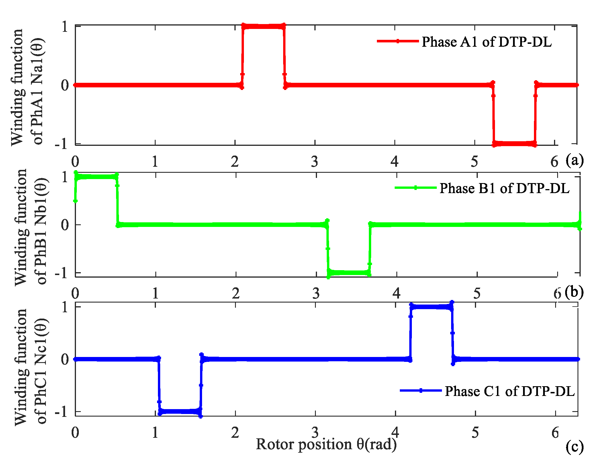
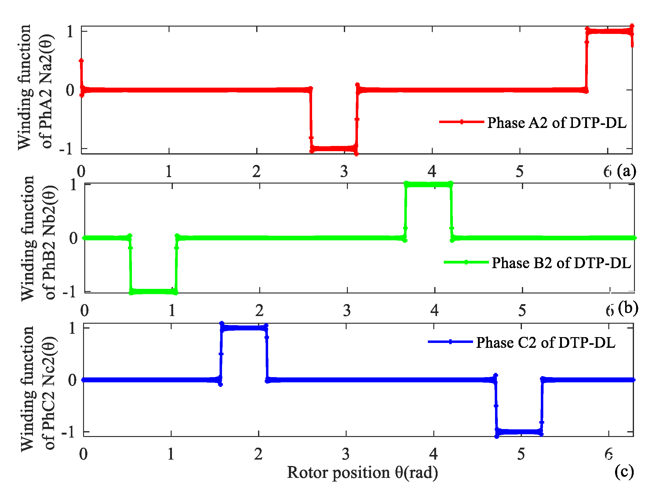
Star graph and winding layout of a 12-slot/10-pole DTP-DL winding are shown in Figure 1. Coil vector and winding distribution of DTP-DL winding are given in Figure 1a,b, respectively. No.①②③… are the position numbers of the stator core (here, stator core is hidden), and No.1 2 3… are the position numbers of slotting winding. It can be seen from the winding distribution (Figure 1b) that DTP-DL winding is composed of two groups of three-phase single layer (TP-SL) with space shift 30 degrees. Winding MMF F(θ, t) is vector sum of each phase winding MMF F1(θ, t), F2(θ, t) and F3(θ, t) analyzed with winding function method. Winding functions NA1(θ), NB1(θ), NC1(θ), NA2(θ), NB2(θ), NC2(θ) of two groups of three phase are given as (2)–(3).
where θ is angular position in rotor reference coordinate (mechanical angle), v is harmonic order, Nc is number of turns per coil.
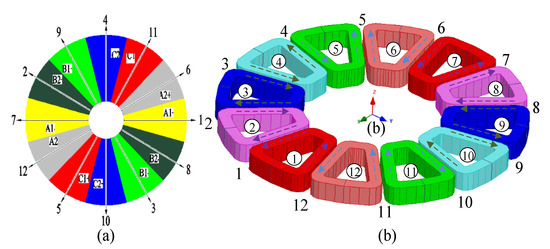
Figure 1.
DTP-DL winding with 12-slot/10-pole combination. (a) Star graph, (b) winding layout.
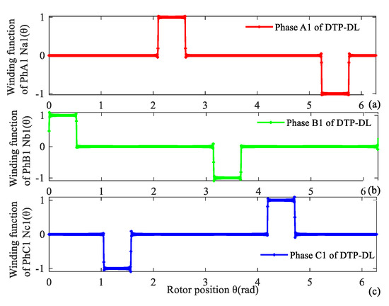
Figure 2.
Winding function of first group of DTP-DL winding. (a) A1, (b) B1, (c) C1.
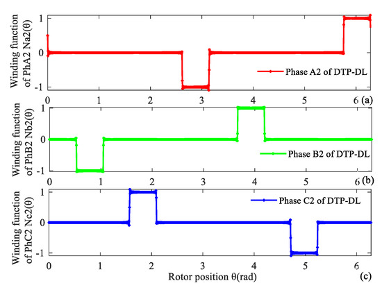
Figure 3.
Winding function of second group of DTP-DL winding. (a) A2, (b) B2, (c) C2.
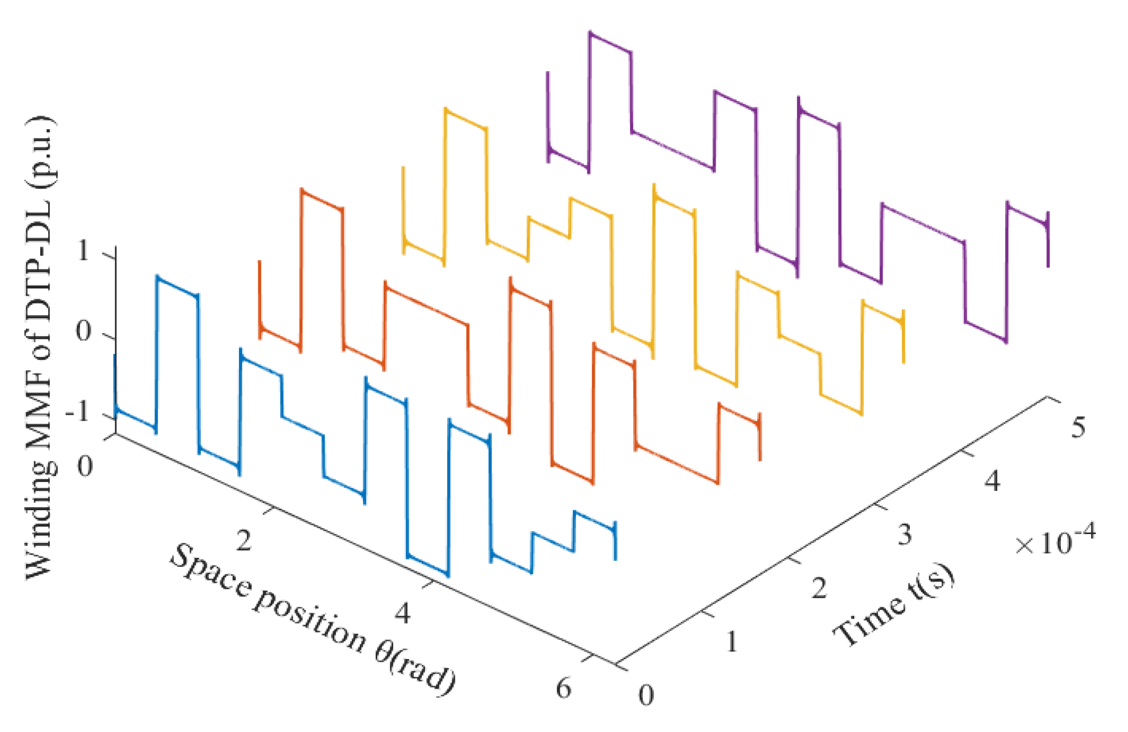
Resultant winding MMF of the DTP-DL winding can be considered as a combination of two groups of the three-phase single-layer (TP-SL) winding. When time t is equal to 0.333 × 10⁻³ s, the normalized values of phase current are equal to iA1 = 0.5 A, iB1 = −1 A, iC1 = 0.5 A, iA2 = 0.866 A, iB2 = −0.866 A, iC2 = 0 A. Analysis result of 12-slot/10-pole DTP-DL winding MMF with WFM is validated by the finite element method (FEM). We find that the analytical result of the winding function method is consistent with FEM as shown in Figure 4. For a 12-slot/10-pole DTP-DL winding, resultant winding MMFs F(θ, t) are a function of time and space, which are given by winding function method as shown in Figure 5. F(θ, t) is a product of winding function N(θ) and current excitation i(t). N(θ) is only related with winding layout. F(θ, t) is related with initial position of curve, winding layout, and phase angle of current excitation.
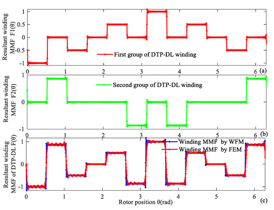
Figure 4.
Resultant winding MMF of 12-slot/10-pole DTP-DL winding at time t = 0.333 × 10⁻³ s. (a) First group of TP winding, (b) second group of TP winding, (c) two groups of TP winding validated by WFM and FEM.

Figure 5.
For 12-slot/10-pole DTP-DL winding, resultant winding MMF changes with time and space.
2.2. TP-FL Winding Function
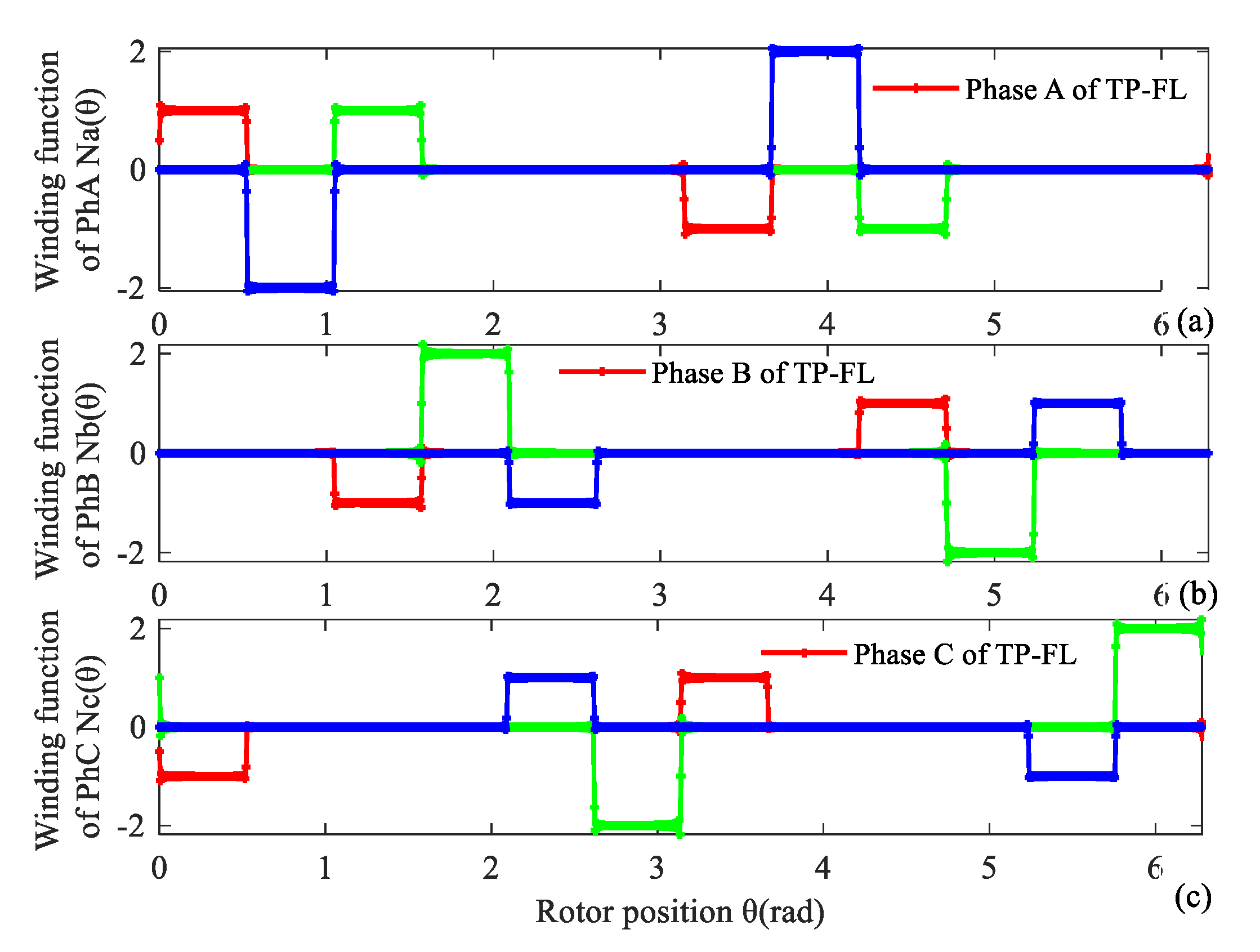
Star graph and winding layout of a 12-slot/10-pole three-phase four-layer (TP-FL) winding are shown in Figure 6. Coil vector and winding distribution of TP-FL winding are given in Figure 6a,b, respectively. It can be seen from the winding distribution (Figure 6b) that TP-FL winding is composed of two groups of three-phase double layer (TP-DL) with space shift 30 degrees.
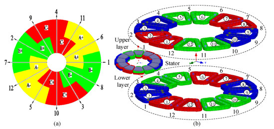
Figure 6.
TP-FL winding with 12-slot/10-pole combination. (a) Star graph, (b) winding layout.
Phase currents of a TP-FL winding can refer to the first groups of DTP-DL winding in (1). The winding MMF is analyzed with the winding function method. Winding functions NA(θ), NB(θ), NC(θ) are expressed as Fourier series in (5). Their corresponding curves of three-phase TP-FL windings are given in Figure 7. We can see that each phase includes four coils in Figure 7.
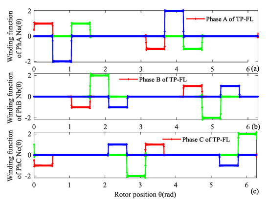
Figure 7.
Winding function of TP-FL winding. (a) Phase A, (b) Phase B, (c) Phase C.
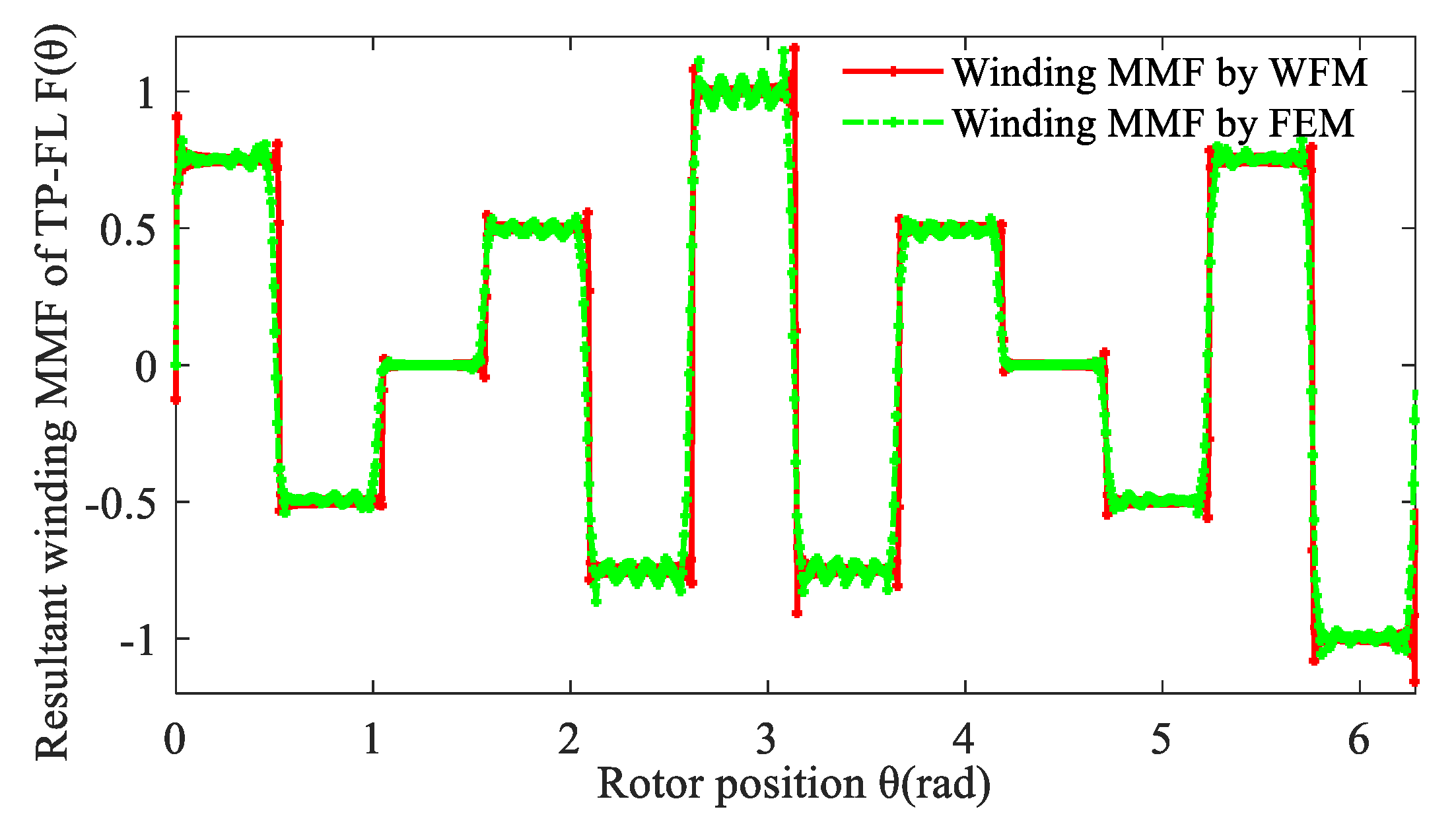
Resultant winding MMF of a TP-FL winding can be considered as a combination of two groups of three-phase double-layer (TP-DL) winding. When time t equals 1.667 × 10⁻³ s, the normalized values of phase current are equal to iA = 0.5 A, iB = 0.5 A, iC = −1 A. Resultant winding MMF curve of TP-FL winding is also validated by the FEM as shown in Figure 8.
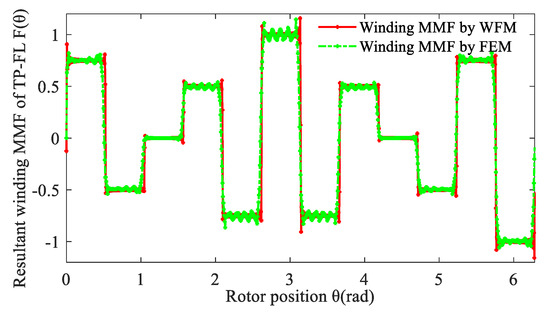
Figure 8.
Resultant winding MMF of 12-slot/10-pole TP-FL winding at time t = 1.67 × 10⁻³ s.
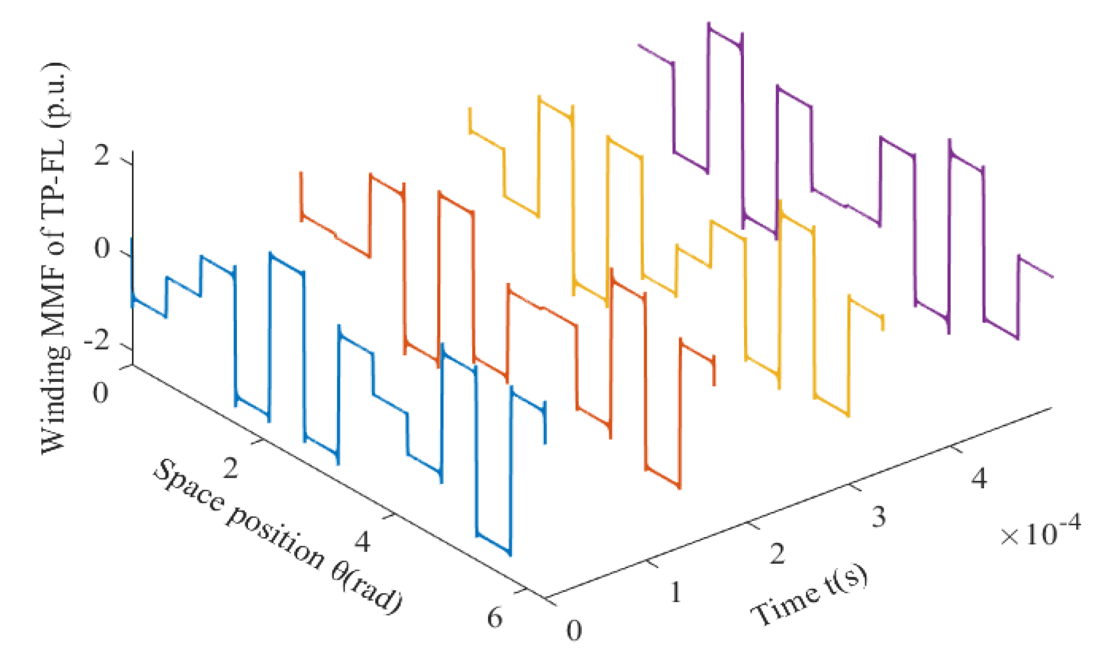
Similarly, for a 12-slot/10-pole TP-FL winding, resultant winding MMFs F(θ, t) are given by winding function method as shown in Figure 9.
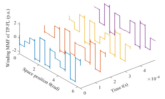
Figure 9.
For 12-slot/10-pole TP-FL winding, resultant winding MMF changes with time and space.
2.3. DTP-FL Winding Function
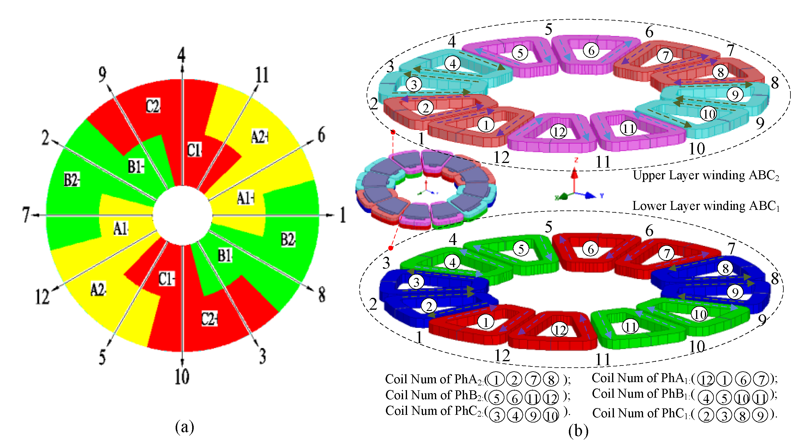
Star graph and winding layout of a 12-slot/10-pole double-three-phase four-layer (DTP-FL) winding are shown in Figure 10. Coil vector and winding distribution of DTP-FL winding are given in Figure 10a,b, respectively. It can be seen from the winding distribution (Figure 10b) that DTP-FL winding is composed of two groups of three-phase double layer with space shift 30 degrees.

Figure 10.
DTP-FL winding with 12-slot/10-pole combination. (a) Star graph, (b) winding layout.
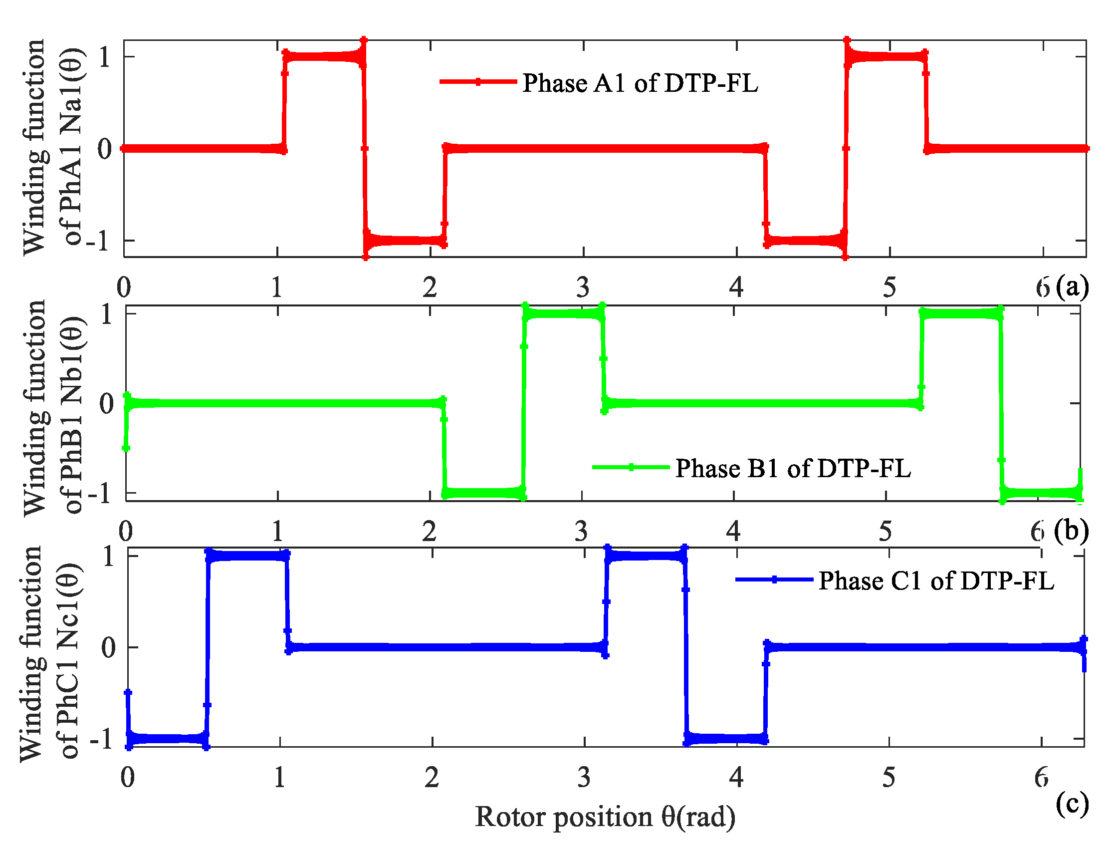
Winding MMF is analyzed with winding function method. Winding functions NA1(θ), NB1(θ), NC1(θ), NA2(θ), NB2(θ), NC2(θ) of two groups of three phase are given as (6), (7). Winding function curves of DTP-FL winding are shown in Figure 11 and Figure 12.
where Nc is number of turns per each coil.
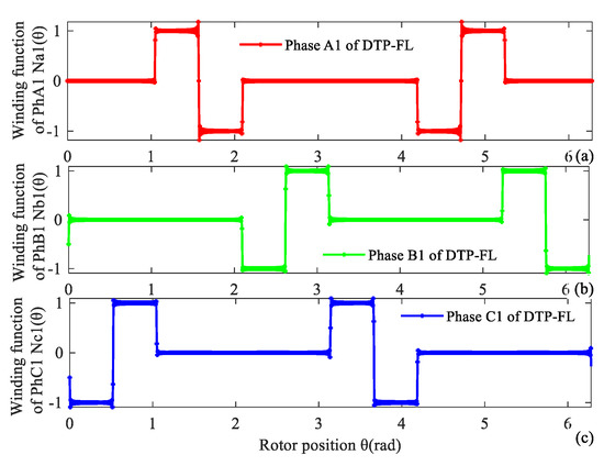
Figure 11.
Winding function of first group of DTP-FL winding. (a) A1, (b) B1, (c) C1.

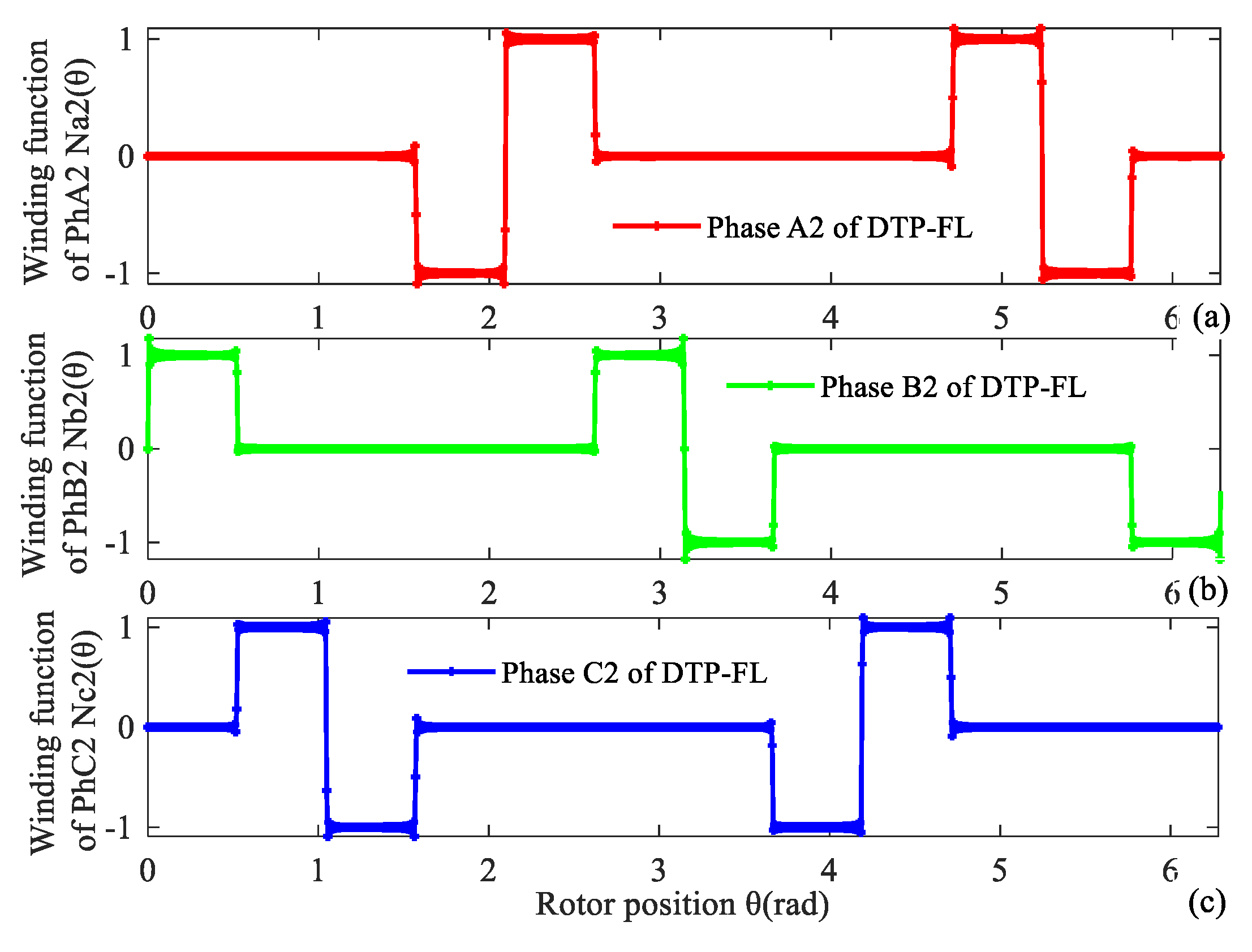
Figure 12.
Winding function of second group of DTP-FL winding. (a) A2, (b) B2, (c) C2.
Resultant winding MMF F(θ, t) is the vector sum of two groups of winding MMF F1(θ, t) and F2(θ, t) as shown in Figure 11 and Figure 12, which are defined as in Equation (8).
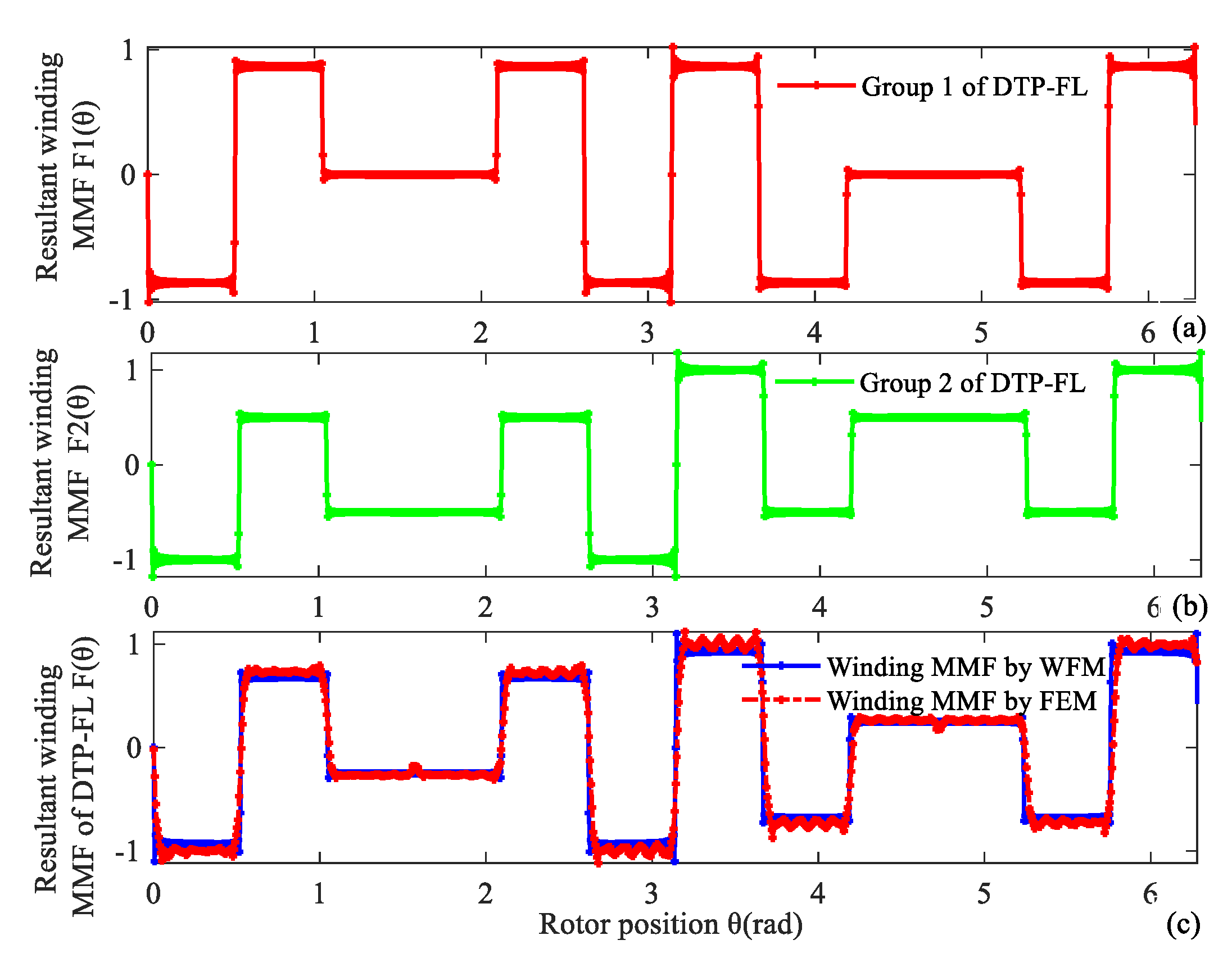
Take time t = 0 s as an example, the normalized values of phase current are equal to iA1 = 0 A, iB1 = −0.866 A, iC1 = 0.866 A, iA2 = 0.5 A, iB2 = −1 A, iC2 = 0.5 A. Resultant winding MMF of DTP-FL winding is also validated by FEM as shown in Figure 13.

Figure 13.
Resultant winding MMF of 12-slot/10-pole DTP-FL winding at time t = 0 s. (a) First group of TP winding, (b) second group of TP winding, (c) two groups of TP winding.
Similarly, for a 12-slot/10-pole DTP-FL winding, resultant winding MMFs F(θ, t) are given by WFM as shown in Figure 14.
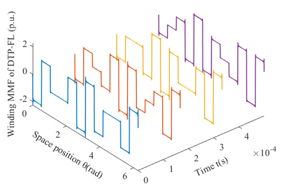
Figure 14.
For 12-slot/10-pole DTP-FL winding, resultant winding MMF changes with time and space.
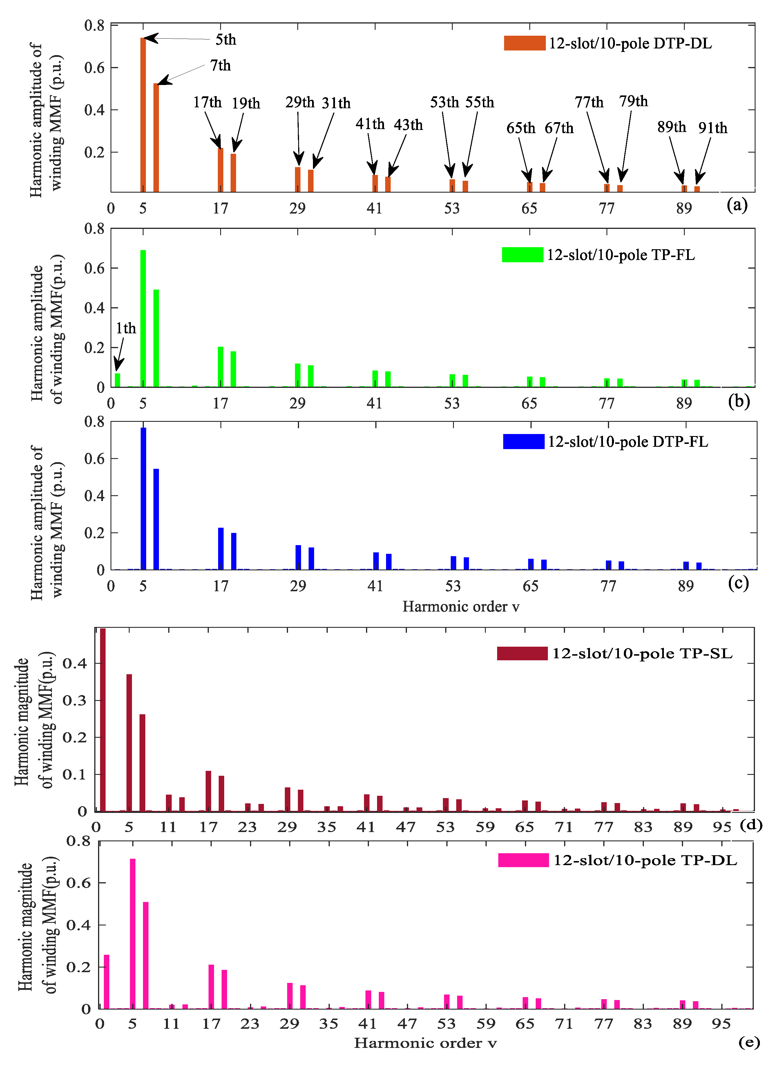
Resultant winding MMFs of 12-slot/10-pole DTP-DL winding, TP-FL winding, and DTP-FL winding change with time and space, which produces wave shift and amplitude change as shown in Figure 5, Figure 9 and Figure 14. For three kinds of multi-phase and multi-layer windings, fast Fourier transform (FFT) of resultant winding MMF is given as in Figure 15a–c. The 5th harmonic is considered to be the fundamental wave for 12-slot/10-pole winding layout. We can see that the TP-SL winding and TP-DL winding have large 1st and small (12n ± 1)th, (n = 1, 2, 3…) harmonics as shown in Figure 15d,e. Total harmonic distortion (THD) of three kinds of winding MMF is given in Table 1. The THD of multi-phase and multi-layer winding MMF can be suppressed relative to THD value of three-phase single-layer (TP-SL: THD = 151.2%) and three-phase double-layer (TP-DL: THD = 79.8%) winding MMF. We can find that the 1st and (12n ± 1)th, (n = 1, 2, 3…) harmonics are suppressed. The THD of winding MMF can be defined as [15].
where are corresponding harmonic amplitudes of the 1st, 5th, 7th order harmonic.
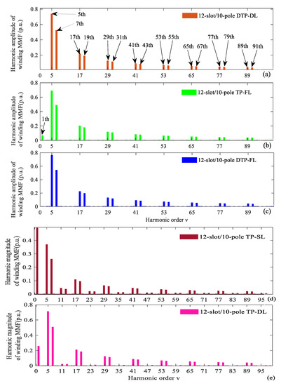
Figure 15.
Harmonic decomposition of winding MMF for 12-slot/10-pole. (a) DTP-DL, (b) TP-FL, (c) DTP-FL, (d)TP-SL, (e) TP-DL.

Table 1.
THD of multi-phase and multi-layer winding MMF.
3. PM MMF and Motor Characteristic
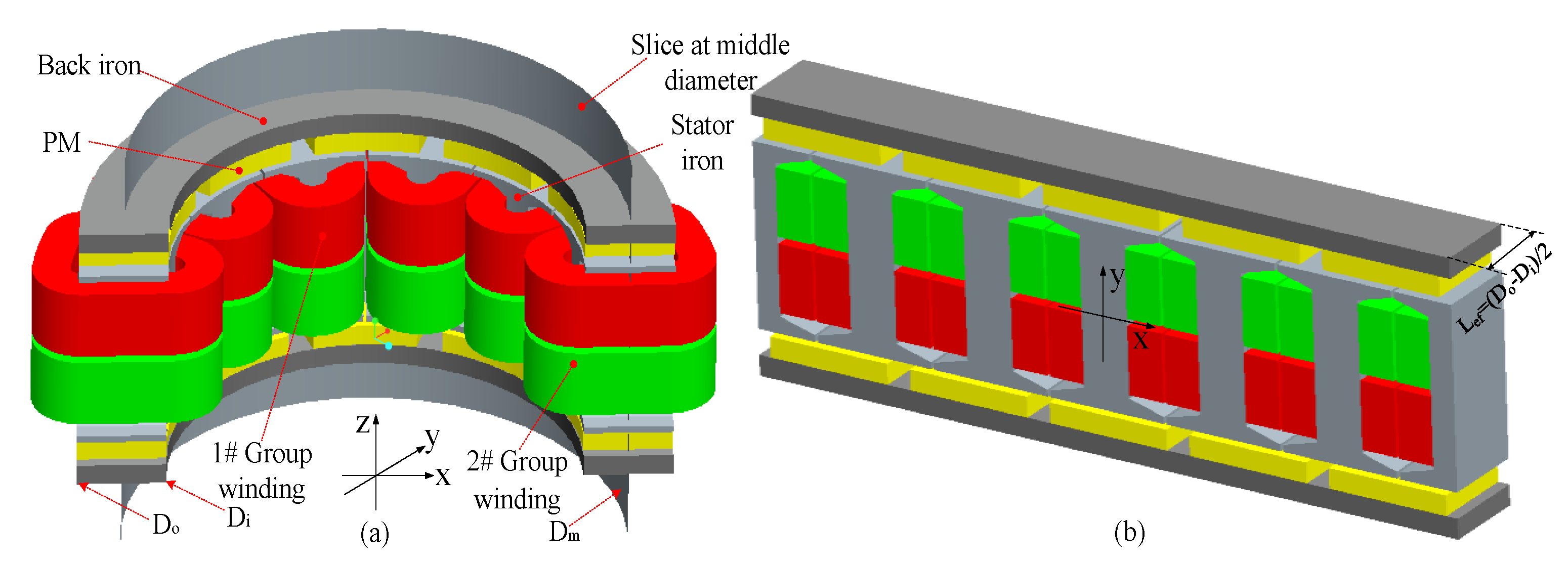
Model evolution process from axial-flux ISG to linear PMSM is given in Figure 16. Axial-flux ISG model (Figure 16a) is unfolded into a linear PMSM model (Figure 16b) by slicing at the middle diameter.
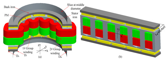
Figure 16.
Axial-flux ISG and LPMSM. (a) Axial-flux ISG, (b) LPMSM at middle diameter.
Main parameters of axial-flux ISG are given in Table 2. There exists a huge magnetic pull force during the assembly process. The uniformity of bilateral air gap length and PM surface magnetic field intensity is hard to guarantee. These factors cause a large unbalanced magnetic pull force, which brings assembly difficulties and axial thrust load on bearings. In order to reduce the magnetic pull force, the actual air gap length adopts conservative design (δ = 2 mm).
Table 2.
Main parameters of axial-flux ISG with DTP-FL winding.
3.1. Rotor PM MMF
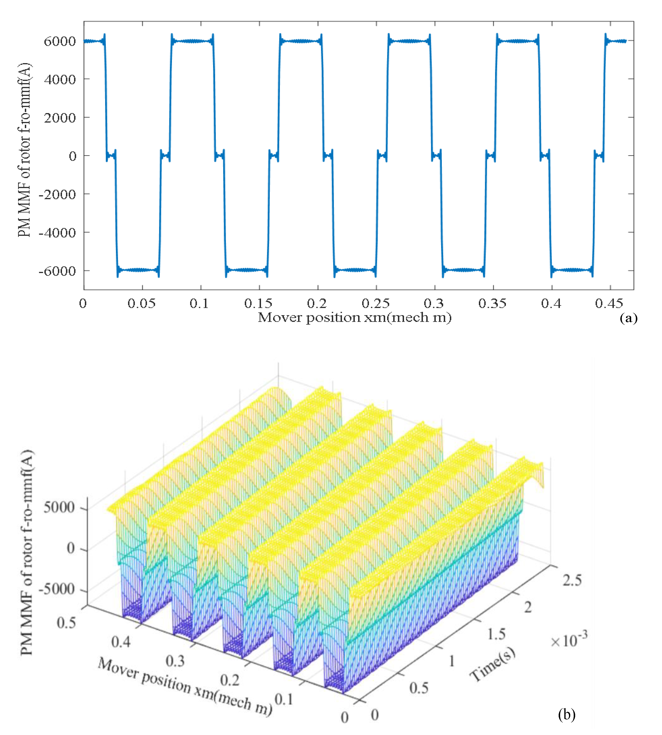
Based on LPMSM model in Figure 16b, rotor PM MMF fpm_mmf(xm, t) is given in [16,17,18].
where kpv is PM pitch-shortening coefficient of vth harmonic; Fpm_mmf is magnitude of rotor PM MMF as follows.
According to (10) and (11), rotor PM MMF fro_mmf changes with mover position xm as is given in Figure 17a. Changes with mover position xm and time t are given in Figure 17b.

Figure 17.
PM MMF (a) changing with space xm, (b) changing with time t and space xm.
3.2. Air Gap Permeance and Relative Air Gap Permeance
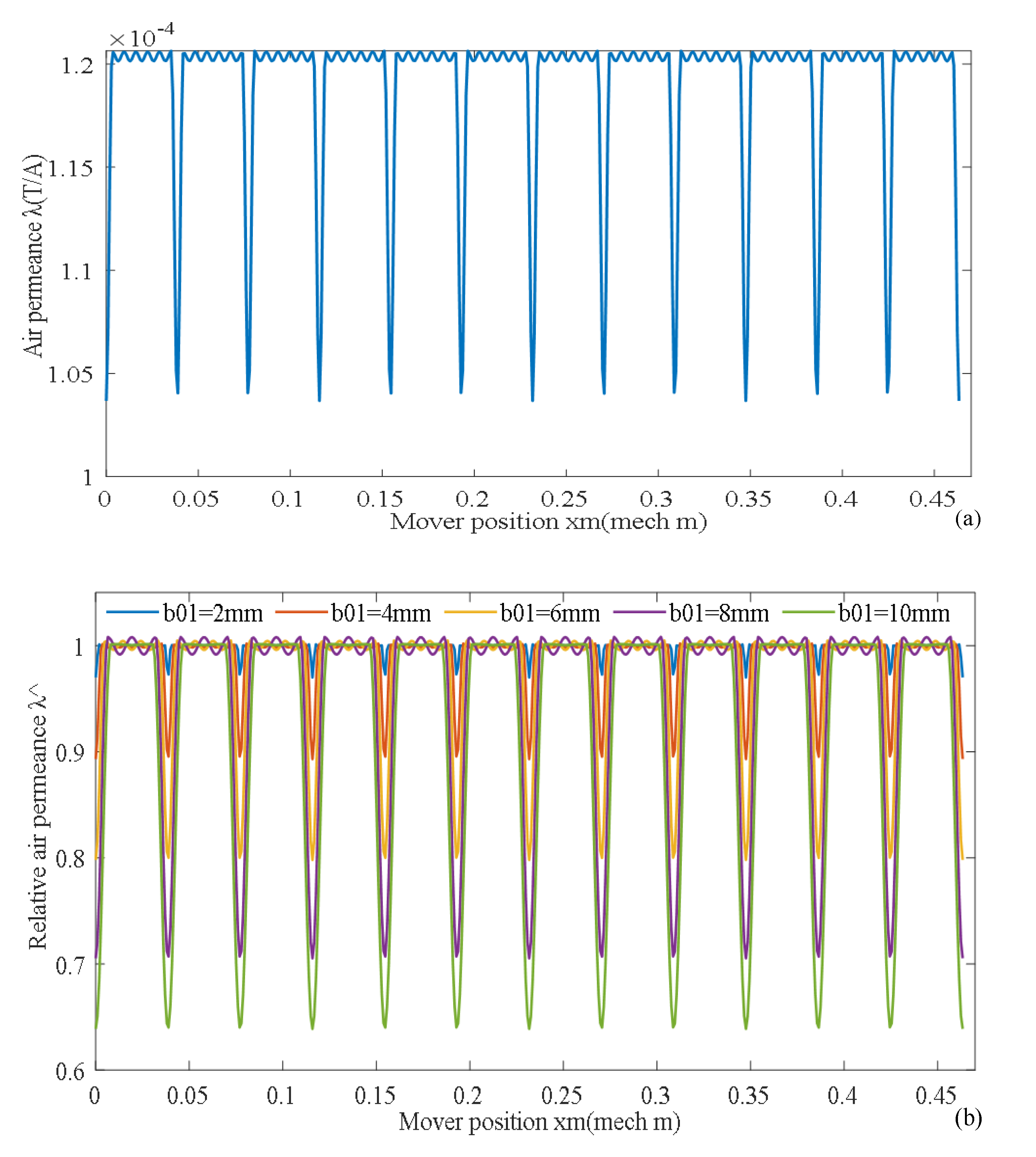
Air gap permeance function λ(xm) expressed by Fourier series and its parameters is given in (12–16) [19,20,21].
where λ0 is constant term of air gap permeance function, δe is effective length of air gap, hpm is thickness along the magnetization direction, μ0 is vacuum permeability, μr is relative permeability of PM, τp is pole pitch, τt is tooth pitch, b01 is width of slot opening.
Karter coefficient Kc and tooth pitch τt are defined as
where Bδmax is maximum air gap flux density, Bδav is average air gap flux density, Dm is middle diameter of stator iron, Q is the number of stator iron slots.
Reduction factor γ of slot width is defined as follows:
Coefficient β and χ are defined as:
Relative air gap permeance function divided by constant term λ0 is given as follows [19,20,21].
According to Equations (12)–(16), air permeance function λ(xm) changes with mover position xm as shown in Figure 18a. According to (17)–(18), relative air permeance function changes with mover position xm as shown in Figure 18b.The larger the slotting opening width, the deeper the air gap permeance pit.
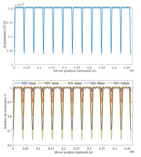
Figure 18.
Air permeance function and relative air permeance function. (a) Air permeance function, (b) relative air permeance with slotting opening width b01.
3.3. Air Gap Flux Density
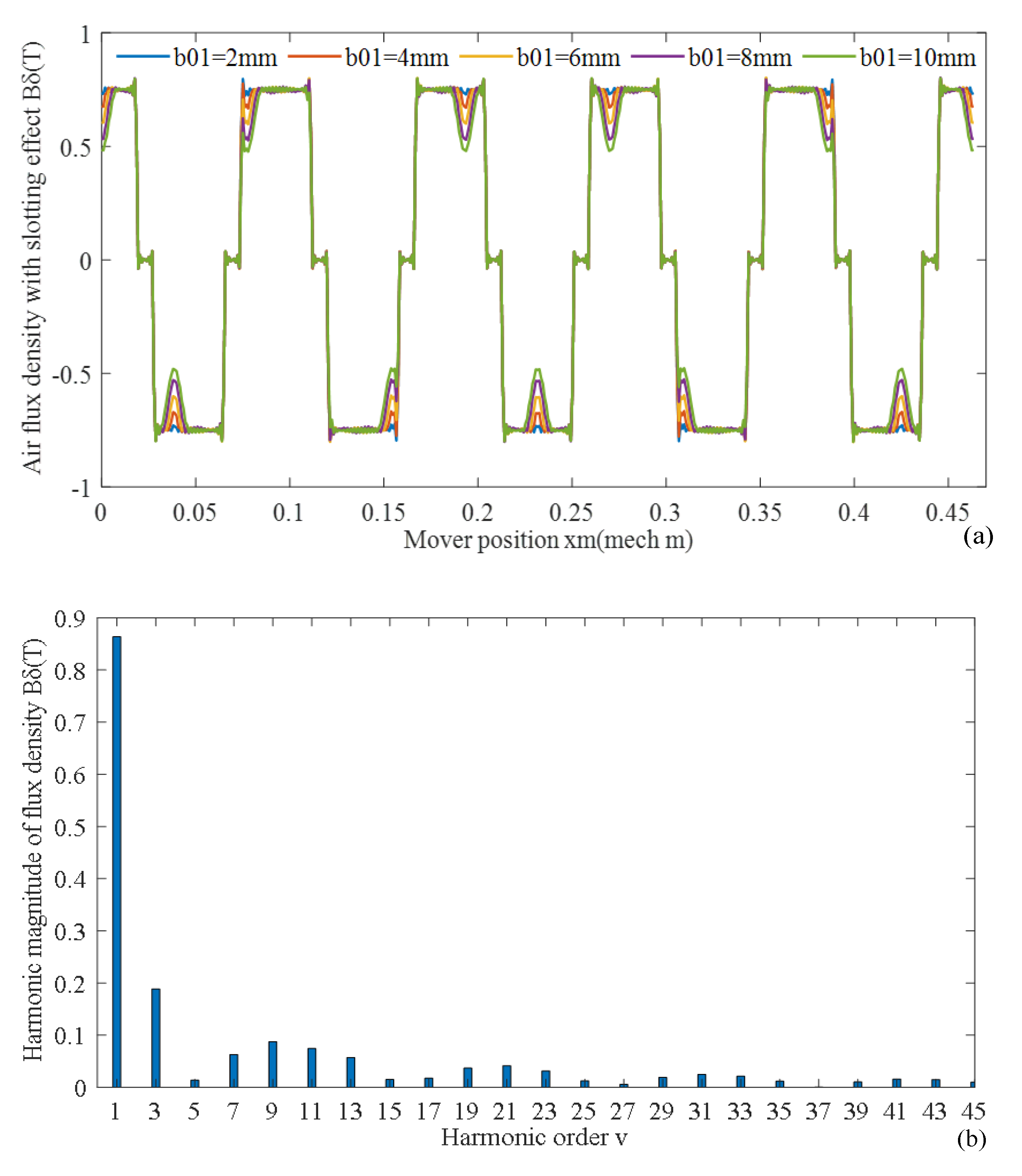
Air gap flux density Bδ_sl(xm,t) corresponding to slotless stator iron is expressed by
Air gap flux density Bδ(xm,t) of slotted stator iron is equal to the product of air gap flux density Bδ_sl(xm,t) of slotless stator iron and relative air gap permeance function , which is given as:
Air gap flux density Bδ(xm,t) and its harmonic magnitude distribution of slotted stator iron are shown in Figure 19a,b. According to (20), air gap flux density Bδ(xm,t) changing with mover position xm and time t is given in Figure 19c. The larger the slotting opening width b01, the more obvious the weakening effect of air gap magnetic density Bδ(xm,t).
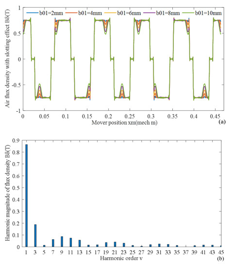
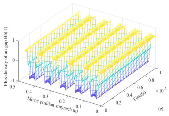
Figure 19.
Air gap flux density (a) changing with slotting opening width b01, (b) FFT, (c) changing with space and time.
In order to validate the analytical result of air gap flux density, a probe of Teslameter is inserted into the air gap to measure its magnetic field strength magnitude of PM as shown in Figure 20. The values are 0.727 T and 0.666 T, respectively, for bilateral air gap. Magnetic field strength of PM surface exhibits inconsistency in the magnetizing process or different leakage flux for different radius and the uneven air gap length. In general, multiple measurements are taken to obtain the average value of magnetic field strength for different rotor positions. A good agreement is realized between the analytical method result (Figure 19a) and the measurement method result (Figure 20).
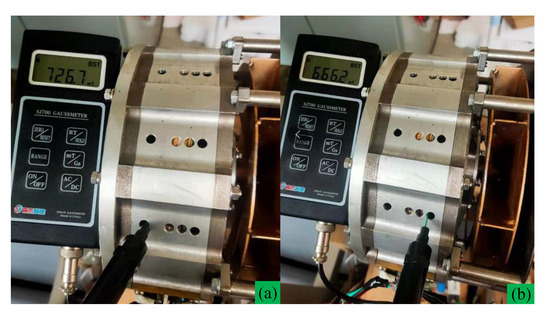
Figure 20.
Measurement of flux density of air gap, (a) drive end side, (b) non-drive end side.
3.4. No-Load Back-EMF
For the corresponding relation between radial-flux PMSM, displacement variable xm and linear velocity vm in LPMSM model correspond to angle variable θm and rotating speed n in radial-flux PMSM, respectively. The angular frequency ω, period T is expressed as follows:
where τp is pole pitch, Dm is middle diameter.
Air gap flux density Bδ(xm, t) can be expressed as a Fourier series of the amplitude Bδmag_n of each harmonic content.
Flux linkage of phase A1 is defined as:
where a is number of parallel branch, N1 is number of turns per phase, kpn is pole pitch coefficient of winding, kdn is distributed coefficient of winding.
No-load back-EMF ephaA1(t) of phase A1 is derivative of flux linkage Ψa(t) as follows:
For the DTP-FL winding, time phase difference of two groups of winding is 30 electric degrees. No-load back-EMF ea1(t), eb1(t), ec1(t), ea2(t), eb2(t), ec2(t) are summarized as:
No-load back-EMF waves by analytical method and FEM are given in Figure 21.
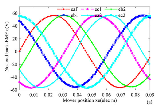
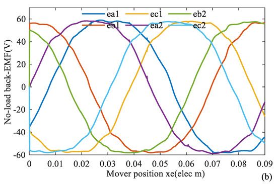
Figure 21.
No-load back-EMF wave of DTP-FL winding (a) analytical method, (b) FEM method.
3.5. Electromagnetic Torque and Its Ripple
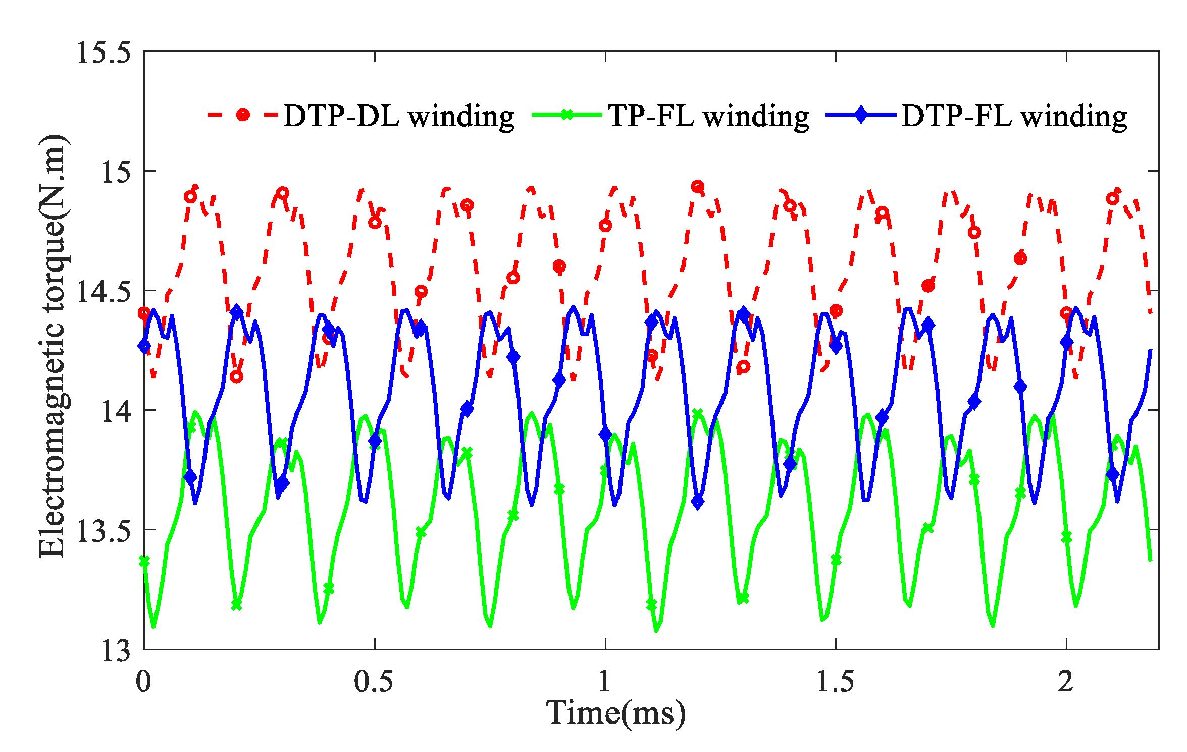
Transient electromagnetic torque T1(t) is calculated for three-phase winding (such as TP-FL winding), and T2(t) is calculated for double-three-phase winding (such as DTP-DL and DTP-FL winding), which are defined as
where Ωm is mechanical angular speed(rpm), ea(t), eb(t), ec(t), ea1(t), eb1(t), ec1(t), ea2(t), eb2(t), and ec2(t) are each phase back-EMF(V), ia(t), ib(t), ic(t), ia1(t), ib1(t), ic1(t), ia2(t), ib2(t), and ic2(t) are each phase current (A). For the same phase current magnitude (I = 11.2 A), the results of T(t) by FEM are given in Figure 22. The average torques of motors with DTP-DL, TP-FL, and DTP-FL winding are 14.6 N·m, 13.6 N·m, and 14.1 N·m, respectively. The torque ripples of motors with DTP-DL, TP-FL, and DTP-FL winding are 5.62%, 6.71%, and 5.67%, respectively.
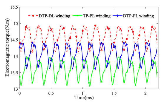
Figure 22.
Transient electromagnetic torque for multi-phase multi-layer winding.
4. Prototype Manufacture and Experiment
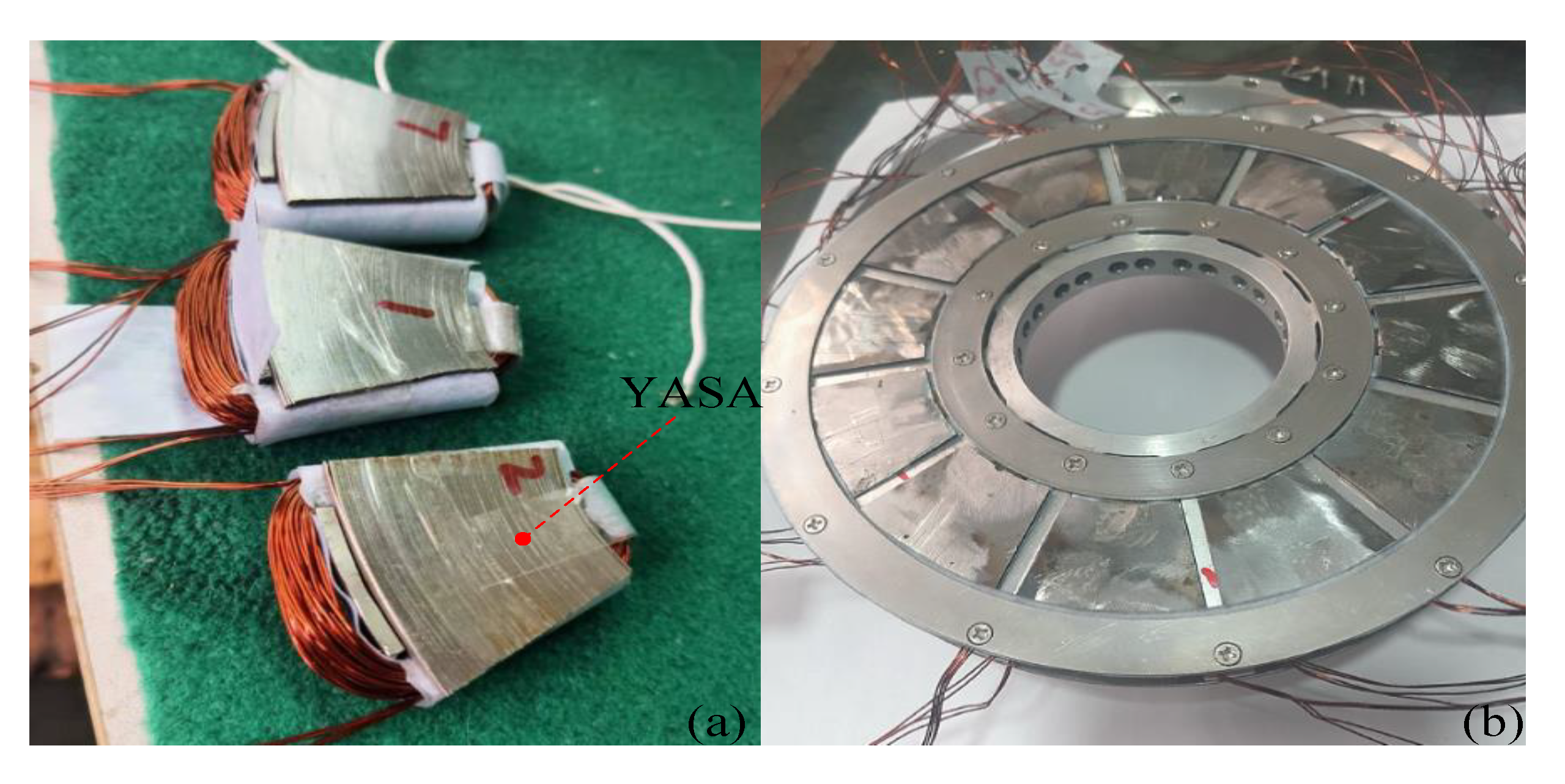
It can be concluded from the above analysis that the 12-slot/10-pole DTP-FL winding has the lowest harmonic THD of winding MMF in Figure 15, which causes low eddy-current loss in PMs. However, a part of electromagnetic torque is sacrificed in Figure 22. To balance high efficiency and torque, a 12-slot/10-pole axial-flux ISG prototype with DTP-FL winding is designed and manufactured. At the same time, axial-flux ISG adopts double-rotor single-stator topology integrated with a centrifugal fan in order to enhance the ability of convective heat transfer. Stator iron is manufactured with laminated iron stacks (35WW270) for low iron core loss. Rotor back iron is made of No. 20 steel for high structural strength. Stator adopts yokeless and segmented armature (YASA) topology to improve power density, and PM adopts radial segmented design to reduce the eddy loss in PMs, which are shown in Figure 23 and Figure 24.
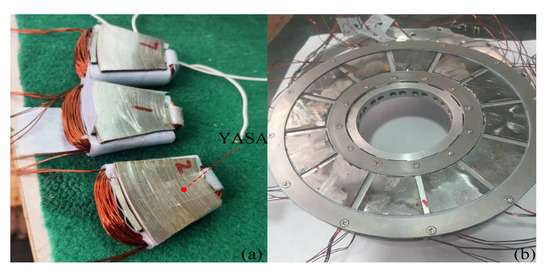
Figure 23.
Stator component (a) single iron with coil, (b) stator.
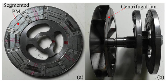
Figure 24.
Rotor component (a) single rotor, (b) two rotors with centrifugal fan.
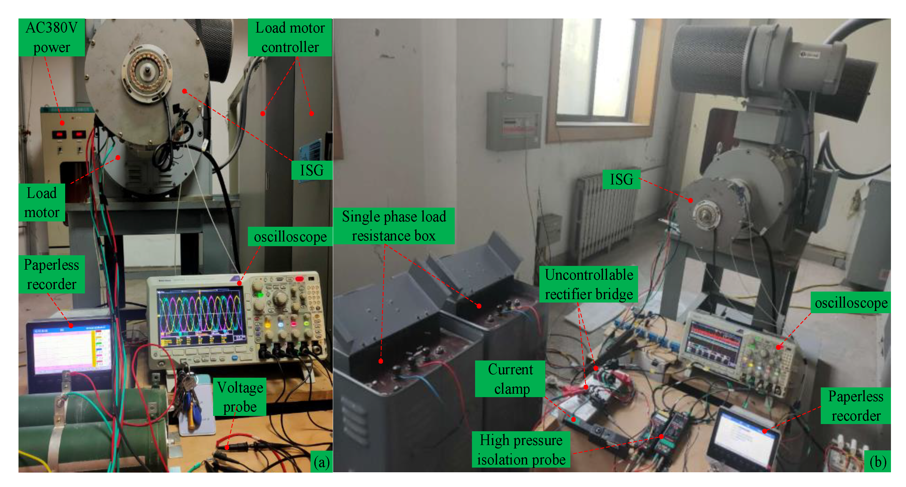
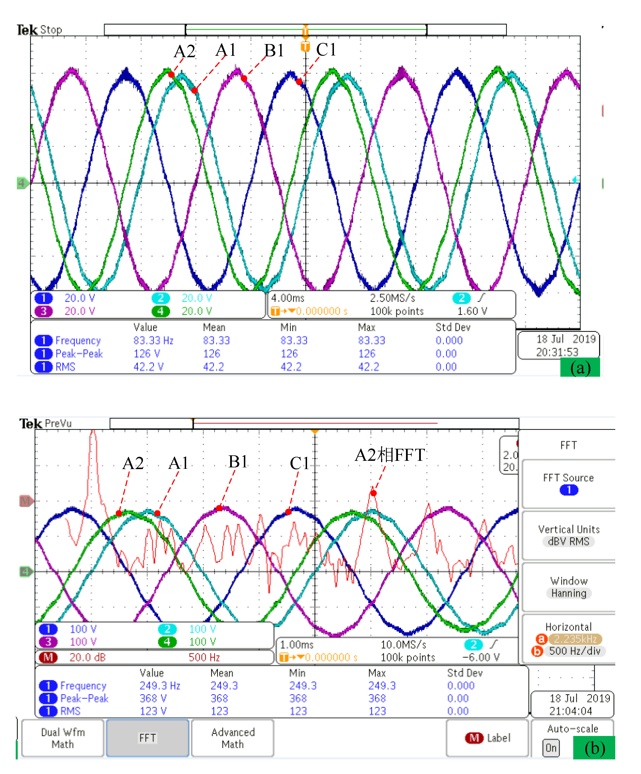
No-load back-EMF and uncontrolled rectifier power generation experiment platform with 65 Ω load resistance are established to evaluate the machine performance in Figure 25. No-load back-EMF, bus current, bus voltage, and output power wave are measured at speed 1000 rpm and 3000 rpm, respectively, in Figure 26 and Figure 27. We can find that the angle between phase A1 and phase A2 is 30 electric degrees, and the no-load back-EMF is close to sine wave with low total harmonic distortion (THD). The result (RMS value: 42.2 V at 1000 rpm) of the no-load back-EMF wave in Figure 26 has validated the correctness of the analytical method result (RMS value: 41 V at 1000 rpm) of no-load back-EMF in Figure 21.
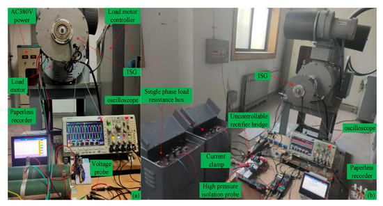
Figure 25.
Test platform of power generation mode. (a) No-load test, (b) load test of two groups of 65 Ω load resistance.

Figure 26.
No-load back-EMF wave of axial-flux ISG at different speeds. (a) speed n = 1000 rpm, (b) speed n = 3000 rpm.
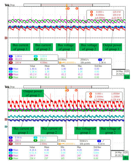
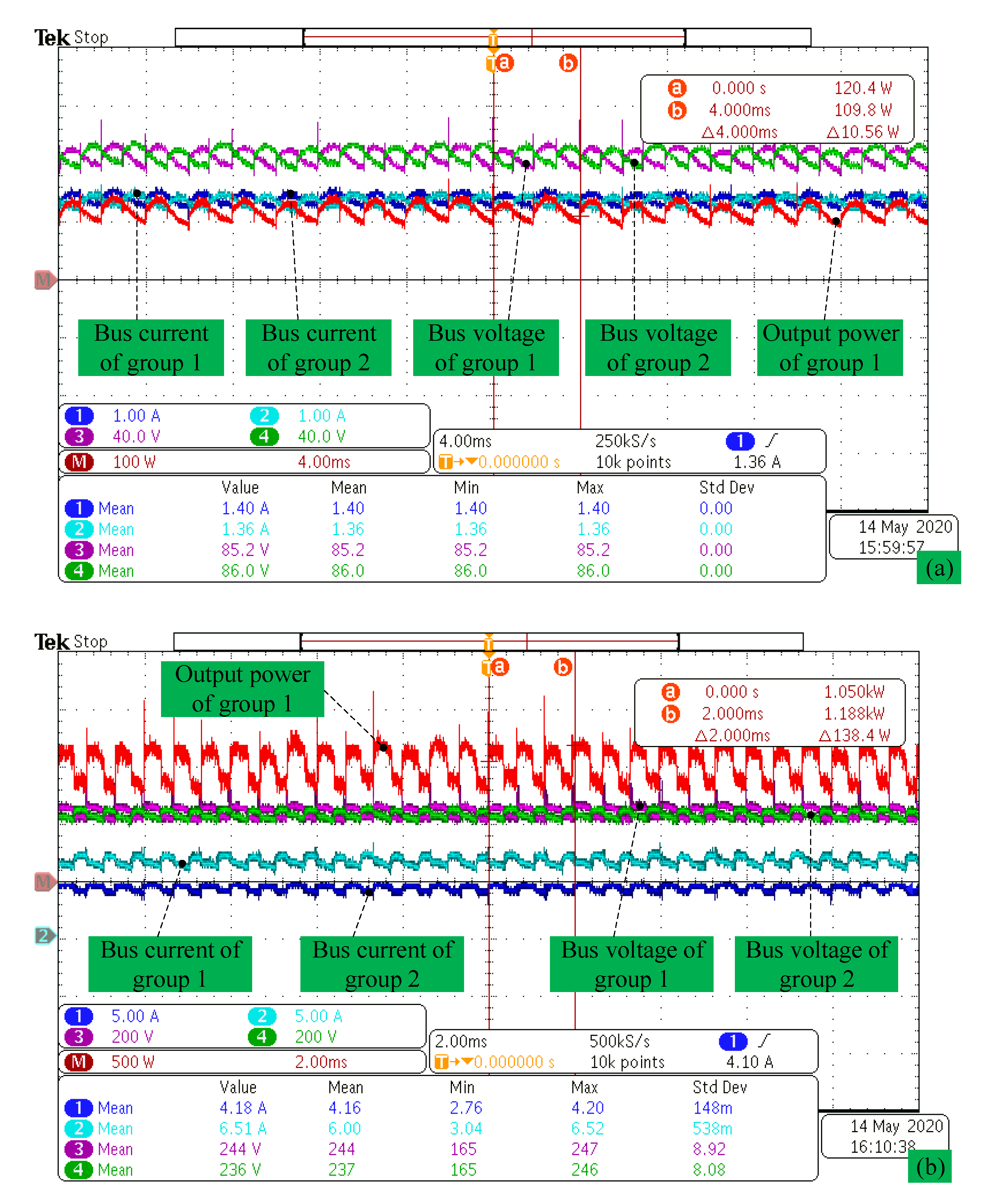
Figure 27.
Bus current, bus voltage, and output power wave. (a) Speed n = 1000 rpm, (b) speed n = 3000 rpm.
Uncontrolled rectifier power generation experiment with R = 65 Ω load resistance is established to calculate output power. We can find that output powers are Pn = 230.2 W at n = 1000 rpm in Figure 27a and Pn = 2.2 kW at n = 3000 rpm in Figure 27b.
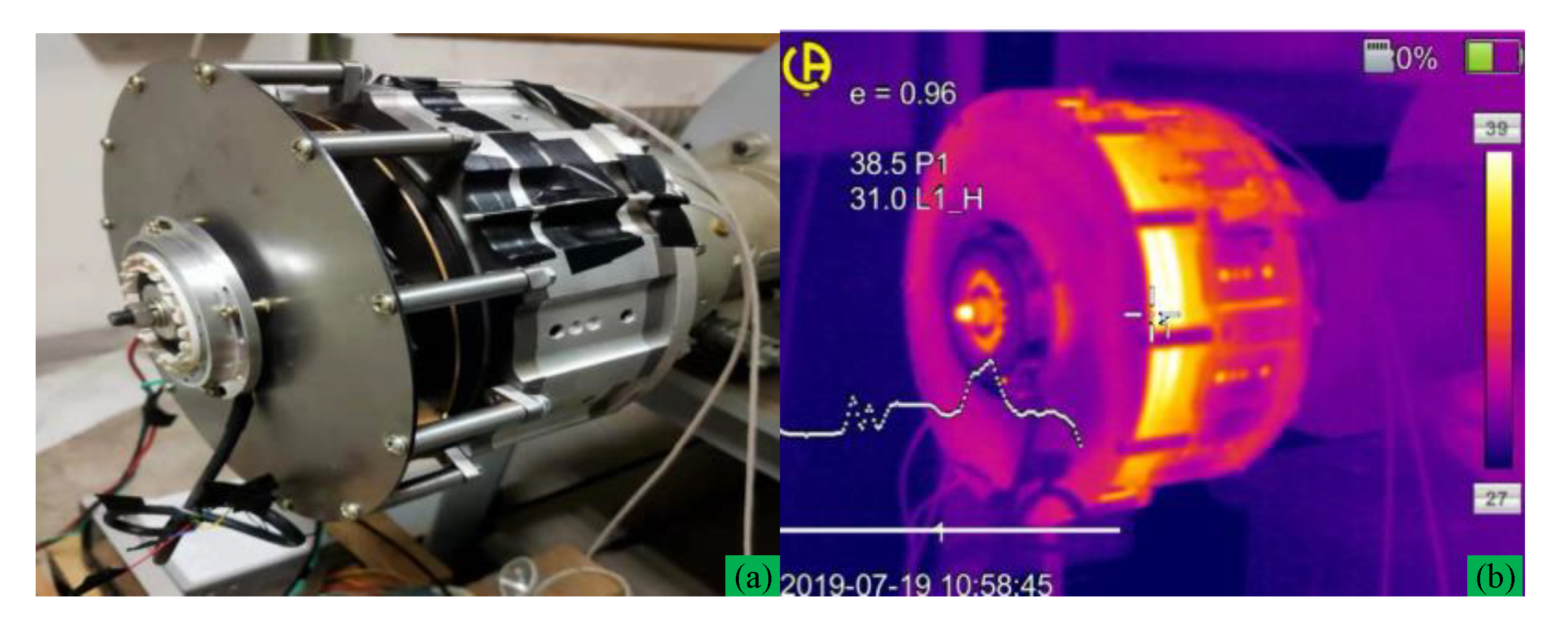
Temperature distribution located at non-driving (Figure 28a) end and driving end (Figure 29a) are measured by thermal image at n = 3000 rpm, load resistance R = 65 Ω, and output power Pn = 2.2 kW, which are shown in Figure 28b and Figure 29b. Due to integrating the centrifugal fan at the non-driving end, the load experiment result shows that ISG operates at a relatively low temperature rise. From infrared thermal (IT) imaging of end cap holes, we can see a low rotor temperature profile (about 50.7 °C) and fan temperature (about 38.5 °C) due to centrifugal fan cooling.

Figure 28.
Non-driving end view of ISG and its thermal image at n = 3000 rpm (a) non-driver side, (b) thermal imaging figure.
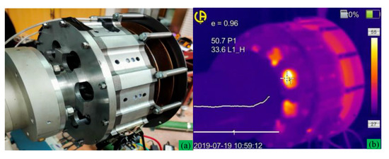
Figure 29.
Driving end view of ISG and its thermal image at n = 3000 rpm (a) driver side view, (b) thermal imaging figure.
5. Conclusions
Winding MMFs of multi-phase and multi-layer winding layout are analyzed by the winding function method. Analysis results show that multi-phase and multi-layer winding can suppress harmonics noticeably, thereby reducing the eddy-current loss in PMs. Winding MMF is validated by FEM. Based on the unfolded LPMSM model, rotor MMF, air gap flux density, and no-load back-EMF are analyzed by the analytical method.
An axial-flux ISG with DTP-FL winding has the advantage of low space harmonic and low eddy-current loss in PMs. Therefore, the prototype scheme with DTP-FL winding is selected to be manufactured. Air gap flux density and no-load back-EMF are validated by Teslameter and no-load experiment. Load experiment with two groups of resistance is established to validate the output power of axial-flux ISG. The temperature distribution of the motor is evaluated with PT100 and infrared thermal imager. Experiments in the resistance load show that axial-flux ISG runs at a relative temperature rise under the action of the centrifugal fan. Winding MMF results with winding function method, PM MMF, and air gap flux density results with air gap permeability function method are directly or indirectly validated by no-load and load experiments.
Author Contributions
Methodology and formula derivation, Q.C.; writing and original draft preparation, Q.C; review and editing, W.C. and Z.Q.; supervision, G.L.; project administration, Q.W. All authors have read and agreed to the published version of the manuscript.
Funding
This research was funded by Key Project of the China National Natural Science Foundation (Project number: 51637001); Open Fund for Collaborative Innovation Center of Industrial Energy-Saving and Power Quality Control, Anhui University (KFKT202101).
Institutional Review Board Statement
Not applicable.
Informed Consent Statement
Not applicable.
Data Availability Statement
Not applicable.
Conflicts of Interest
The authors declare no conflict of interest.
References
- Alberti, L.; Bianchi, N. Theory and design of fractional-slot multilayer windings. IEEE Trans. Ind. Appl. 2013, 49, 841–849. [Google Scholar] [CrossRef]
- Wang, Y.; Qu, R.; Li, J. Multilayer windings effect on interior PM machines for EV applications. IEEE Trans. Ind. Appl. 2015, 51, 2208–2215. [Google Scholar] [CrossRef]
- Abdel-Khalik, A.S.; Ahmed, S.; Massoud, A.M. Effect of multilayer windings with different stator winding connections on interior PM machines for EV applications. IEEE Trans. Magn. 2016, 52, 1–7. [Google Scholar] [CrossRef]
- Rallabandi, V.; Taran, N.; Ionel, D.M. Multilayer concentrated windings for axial flux pm machines. IEEE Trans. Magn. 2017, 53, 1–4. [Google Scholar] [CrossRef]
- Sun, A.; Li, J.; Qu, R.; Li, D. Effect of multilayer windings on rotor losses of interior permanent magnet generator with fractional-slot concentrated-windings. IEEE Trans. Magn. 2014, 50, 1–4. [Google Scholar] [CrossRef]
- Lu, Y.; Li, J.; Lu, H.; Qu, R.; Xiao, L.; Li, D.; Zhang, R. Six-phase double-stator inner-rotor axial flux PM machines with novel detached winding. IEEE Trans. Ind. Appl. 2017, 53, 1931–1941. [Google Scholar] [CrossRef]
- Abdel-Khalik, A.S.; Ahmed, S.; Massoud, A.M. A six-phase 24-slot/10-pole permanent-magnet machine with low space harmonics for electric vehicle applications. IEEE Trans. Magn. 2016, 52, 1–10. [Google Scholar] [CrossRef]
- Reddy, P.B.; El-Refaie, A.M.; Huh, K.K. Effect of number of layers on performance of fractional-slot concentrated-windings interior permanent magnet machines. IEEE Trans. Power Electron. 2015, 30, 2205–2218. [Google Scholar] [CrossRef]
- Bianchi, N.; Bolognani, S.; Pre, M.D.; Grezzani, G.A.G.G. Design considerations for fractional-slot winding configurations of synchronous machines. IEEE Trans. Ind. Appl. 2006, 42, 997–1006. [Google Scholar] [CrossRef]
- Hwang, C.C.; Chang, C.M.; Hung, S.S.; Liu, C.T. Design of high performance flux switching PM machines with concentrated windings. IEEE Trans. Magn. 2014, 50, 1–4. [Google Scholar] [CrossRef]
- Aslan, B.; Semail, E.; Legranger, J. General analytical model of magnet average eddy-current volume losses for comparison of multiphase PM machines with concentrated winding. IEEE Trans. Energy Convers. 2014, 29, 72–83. [Google Scholar] [CrossRef] [Green Version]
- Abdel-Khalik, A.S.; Ahmed, S.; Massoud, A.M. Low space harmonics cancelation in double-layer fractional slot winding using dual multiphase winding. IEEE Trans. Magn. 2015, 51, 1–10. [Google Scholar] [CrossRef]
- Ji, J.; Luo, J.; Zhao, W.; Zheng, J.; Zhang, Y. Effect of circumferential segmentation of permanent magnets on rotor loss in fractional-slot concentrated-winding machines. IET Electr. Power Appl. 2017, 11, 1151–1159. [Google Scholar] [CrossRef]
- Nair, S.S.; Wang, J.; Chin, R.; Chen, L.; Sun, T. Analytical prediction of 3-D magnet eddy current losses in surface mounted PM machines accounting slotting effect. IEEE Trans. Energy Convers. 2017, 32, 414–423. [Google Scholar] [CrossRef]
- Kabir, M.A.; Husain, I. Application of a multilayer AC winding to design synchronous reluctance motors. IEEE Trans. Ind. Appl. 2018, 54, 5941–5953. [Google Scholar] [CrossRef]
- Liu, X.; Hu, H.; Zhao, J.; Belahcen, A.; Tang, L.; Yang, L. Analytical solution of the magnetic field and EMF calculation in ironless BLDC motor. IEEE Trans. Magn. 2016, 52, 1–10. [Google Scholar] [CrossRef]
- Zhu, L.; Zhu, J.; Tong, W.; Han, X. Analytical method of no-load iron losses of axial flux amorphous alloy permanent magnet motor. Zhongguo Dianji Gongcheng Xuebao/Proc. Chin. Soc. Electr. Eng. 2017, 37, 923–930. [Google Scholar]
- Guo, B.; Huang, Y.; Peng, F.; Guo, Y.; Zhu, J. Analytical modeling of manufacturing imperfections in double-rotor axial flux PM machines: Effects on back EMF. IEEE Trans. Magn. 2017, 53, 1–5. [Google Scholar] [CrossRef] [Green Version]
- Qazalbash, A.A.; Sharkh, S.M.; Irenji, N.T.; Wills, R.G.; Abusara, M.A. Calculation of no-load rotor eddy-current power loss in PM synchronous machines. IEEE Trans. Magn. 2014, 50, 1–8. [Google Scholar] [CrossRef] [Green Version]
- Wang, X.H.; Li, Q.F.; Wang, S.H. Analytical calculation of no-load air-gap magnetic field and back electromotive force in brushless dc motor. Proc. Csee 2003, 23, 126–130. [Google Scholar]
- Souissi, A.; Abdennadher, I.; Masmoudi, A. Analytical prediction of the no-load operation features of tubular-linear permanent magnet synchronous machines. IEEE Trans. Magn. 2016, 52, 1–7. [Google Scholar] [CrossRef]


Publisher’s Note: MDPI stays neutral with regard to jurisdictional claims in published maps and institutional affiliations. |
© 2021 by the authors. Licensee MDPI, Basel, Switzerland. This article is an open access article distributed under the terms and conditions of the Creative Commons Attribution (CC BY) license (https://creativecommons.org/licenses/by/4.0/).