1. Introduction
Due to the dynamic development of automation and robotics, alternative actuator solutions have increasingly been used in recent times. This can be seen in particular in soft robotics, where actuators or sensors are used to convert energy in smart materials. One group of such smart materials are Dielectric Electroactive Polymers (DEAPs). DEAPs offer excellent performance, are flexible, lightweight and inexpensive. These materials have developed very dynamically in recent times and are increasingly used in innovative constructions, such as pumps, robots, valves or micro-positioning systems [
1,
2,
3].
Accurate modeling of the DEAP actuator phenomena is important for designers working with these materials. It is an important problem which is still extensively analyzed in the literature [
2,
4,
5,
6]. One of the interesting issues is the analysis of actuator shapes. The most common actuators used in the solutions presented so far have the shape of a circle. This paper presents an elliptical actuator model described with a circular approximation. The paper presents the experiments carried out for three different actuators with different geometries. Finite element model (FEM) modeling of the behavior of DEAPs is useful to understand such systems better and help in the optimal design of prototypes [
7,
8]. An FEM-based simulation was performed, which demonstrated its applicability to compare stress distribution in the three configurations of DEAP actuators.
DEAP actuators can operate with a variety of input and output signals, but in the most common configuration the voltage is the input and displacement is the output [
4,
9,
10]. In order to increase the operating range of DEAP actuators, various biasing mechanism are used, for example, a mechanical spring [
3,
4,
9]. There are also other solutions to achieve greater tension, such as magnetic coupling [
11]. In this research, the actuator membranes were loaded with additional mass, similar to the works [
6,
12,
13].
Measurements of the displacement of elliptical and circular actuators were analyzed, and then the process of identifying model parameters was discussed. The process of identifying the dynamic parameters of the model with the use of the actuators’ displacement responses to the step input voltage is presented and illustrated.
2. Motivation
In this section, the motivation of this study is presented. In recent times, the circular shape of DEAP actuator has commonly been applied in different configurations [
14,
15,
16]. In the presented work, the idea is to exploit the anisotropy of many devices (such as, for instance, a pipe with an installed pump), which allows one direction to be extended while the second must be limited. The motivation of our modification is to provide more energy in the device. Let us consider two cases: a circle with radius
and an ellipse with semi-minor axis
and semi-major axis
, satisfying
. The area of circle
and area of ellipse is
; hence,
. If the circle or ellipse is covered by the electrodes like in the DEAP actuators, the capacity of both devises approximated by parallel plate capacitor will be:
where
d is the distance between the electrodes and
is the permittivity of the material. It is clear that
; therefore, the energy stored in the elliptical device under a constant voltage (
, [
17]) is larger than in the circular device. Therefore, it is expected that the elliptical shape will cause different responses compared to the circular shape.
3. DEAP Elliptical Actuator Model
The DEAP actuator models have been widely studied in the literature [
1,
6,
18,
19], showing the most significant phenomena in these devices. This work applies the knowledge of these works to analyze the proposed elliptical actuator. The mass biased actuator was chosen for simplicity of biasing mechanics [
6]. However, it is also possible to apply the proposed work with different bias mechanics [
15,
16,
19]. The aim is to model the elliptical actuator as an extension of the circular one. The elliptical shape actuator model was defined using two circular model actuators (
), as presented in
Figure 1. The approximation was based on the use of a model consisting of two circular actuators with radii corresponding to the minor (
) and major (
) semi-axis of the elliptical actuator.
In the first step, the basic relationships for two circular models (indexed by
for simplicity) are redefined. In general, the DEAP membrane has the following property:
which comes from the assumption on the constant volume of material during deformation. The variables
,
and
are radial, circumferential, and vertical stretches (taking into account also the initial prestretch of the DEAP membrane applied in the production process [
20]).
The basic formulas of the DEAP actuator are defined for two circular actuators:
The variables for the undeflected state (without applied mass and voltage) are given by
and
, which are the membrane initial thickness and the electrode width. The membrane is assumed to be the same for all elliptical shapes (with circular prestretch); therefore, the initial thickness is common for both models. The electrode width depends on the length of minor/major semi-axis; hence, it must include the index of the actuator. In the case of the deflected state (with applied mass or voltage), the variables are
and
. In this case, both variables are different due to different stretch for small and large circular actuators. The function
is applied to clarify the notation. To simplify the analysis of relationship, the cross-sections of both actuators (for short and long axis) are presented in
Figure 2. It is assumed that both actuators move over the same distance
y because they express the single elliptical actuator. However, it is worth pointing out that angles
will be different for both axes:
In the second step, the vertical force equilibrium is considered taking into account the biasing mass:
where
g denotes the standard gravity and
r is the radius of the internal mass
m,
is vacuum permittivity,
is the relative permittivity of the actuator membrane,
u is the applied voltage and
is the mechanical stress of the individual circular actuators.
The influence of small and large circular actuators on the elliptical one is weighted by the choice of the appropriate coefficient
. It was assumed that the behaviour of the elliptical actuator will be between the small and large actuator; hence, the sum of these factors is 1:
It is worth emphasizing that the presented model of the elliptical model extends the circular model. If it was considered that an ellipse is a circle (
), then the model is reduced to single circle, as presented in [
6].
Circular actuators approximating the description of the elliptical actuator have different mechanical stresses
:
where:
defines the Ogden model representing the hyperelastic properties of the DEAP membrane,
is the viscoelastic stress and
specifies the viscous damper.
The applied third level (
) Ogden model, with two parameters,
and
, integrates the prestretch into the strain energy function. The identification of the
and
parameters was carried out taking into account prestretch; thus, the obtained values of the Ogden model take into account the phenomenon of initial stretching of the actuator membrane.
The phenomenon of viscoelasticity of the individual circular cylinders was modeled by a series connection of a viscous damper and an elastic spring (
) and the viscous damper (
) connected parallel to them, as presented in
Figure 3.
Each of the circular actuators has different
, so they have different strains of the damper
, while maintaining the same material properties (
,
and
), whose values and other information are listed in
Table 1 (the identification process is described in the following section).
The Stress Analysis of the Actuator’s New Geometries
In this section, FEM analysis of the proposed actuators is performed. The FEM simulation was included to show the stress distribution in circular and elliptical actuators for the same material parameters. The goal of analysis is to see the influence of geometry change on the DEAP actuator. The main advantage of circular geometry is its radial symmetry. However, as will be shown in the experimental section, the elliptical shape allows a wider range of movement. As an example, three geometries are considered: circular, small elliptical and large elliptical. The internal plate has a constant shape of the cylinder. The outer side of the membrane is fixed and a pressure is applied to the internal plate. The Young modulus and Poisson ratio are the same for all configurations. The simulations were performed by the FEM module in FreeCAD software. In all cases, the membrane deformed to counteract pressure. The deformation was largest for the large elliptical shape and smallest for the circular shape. Using these simulations, it was shown that this distribution depends on the shape of the actuator. In
Figure 4, the stress in all cases is shown. It is visible that for the circular shape the stress has a radial symmetry. In the case of the elliptical shape, the stress is larger for the shorter axis than for longer axis. It is especially visible for the large elliptical shape. However, the ultimate goal is to control the object-oriented model of elliptical actuators. The simulations included in this section are only a visualization of the distribution of these stresses in the three DEAP actuator configurations.
4. Experiments
The model presented above was experimentally verified with the use of three DEAP actuators with different geometries. The actuators were made of acrylic membrane (3M VHB tape), which was stretched on a plexiglass frame. The VHB tape was also prestretched, similarly to [
20]. To obtain the same prestretch for all actuators, the prestretch was carried out for a circular frame larger than the largest elliptical actuator. The prestretch factor was 5, providing a change in thickness from 1 mm to 200
. The membrane is elastic (with a Poisson ratio slightly below 0.5), and hence the volume of the membrane during stretching process was constant. The electrodes were made of carbon grease and covered the entire surface of the actuators on both sides. The electrodes created a capacitor whose electrostatic field caused membrane compression. One actuator was circular, while the other two had elliptical shapes. The dimensions of the actuators are presented in
Table 1. In the center of each actuator, there was a plexiglass circle on which additional mass was placed during the experiments. Two copper connections were glued to the carbon electrodes to apply the supply voltage (
Figure 5).
The experiments were performed on the following hardware: a high voltage amplifier TREK MODEL 10/10B-HS, a laser distance sensor Micro-Epsilon optoNCDT ILD1320-10 with 1
accuracy, and an Inteco RT-DAC/USB data acquisition card. The laboratory set-up is presented in
Figure 6. The system was measuring data with a probe time of 1
.
Table 1.
Parameters of DEAP actuator models.
Table 1.
Parameters of DEAP actuator models.
| Parameter | Symbol | Value | Units |
|---|
| Actuator name | | Circular | Elliptical small | Elliptical large | |
| Inner radius | r | 1 | |
| Outer radius (short) | | | |
| Outer radius (wide) | | | 6 | | |
| Electrode surface | S | | | | |
| Membrane initial thickness | | 1 | |
| Membrane final thickness | | 200 | |
| Standard gravity | g | 9.81 | |
| Coefficient | | 0.73 | - |
| Coefficient | | 0.27 | - |
| Vacuum permittivity | | | |
| Relative permittivity | | | - |
| Coefficient of viscoelastic model | | | |
| Coefficient of viscoelastic model | | | |
| Damping coefficients | | | |
| Hyperelastic model coefficient | | | |
| Hyperelastic model coefficient | | | |
| Hyperelastic model coefficient | | | |
| Hyperelastic model coefficient | | | |
| Hyperelastic model coefficient | | | |
| Hyperelastic model coefficient | | | |
4.1. Identification-Static Parameters
The identification procedure of the circular actuator was studied in the previous works [
6,
19]. The presented approach extends the previous procedure to identify three models with the same set of mechanical and electromechanical parameters. Firstly, the measured static characteristics were exploited to search the values of the Ogden model coefficients, the weight coefficients
,
and relative permittivity. To find the model parameters, the following optimization problem is solved:
where
is the geometry coefficient,
M is the number of the steady state responses and
P is the number of different masses applied in the identification process. The optimization process required only the determination of the
value, because according to Formula (
6), the
parameter was the difference
.
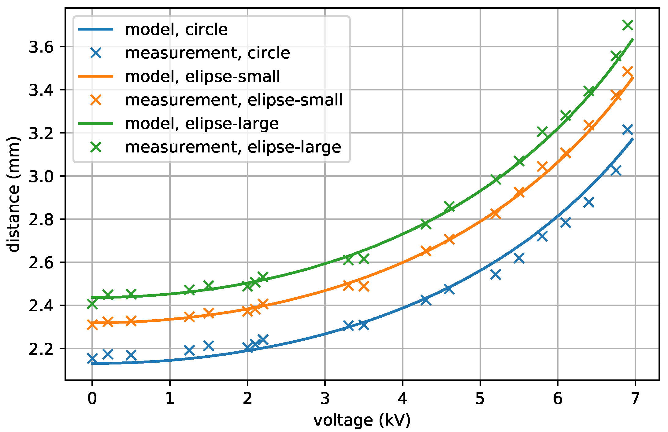
The actuator displacement measurements were carried out for the range 0w–7with loads of
and
. After changing the voltage, there was a 30 s wait before the actuator displacement was stabilized. The steady state responses of distance obtained for the following voltages were used to optimize the parameters of the Ogden model, the weight coefficients
and relative permittivity. The SciPy python package [
21] was used to run a Nelder–Mead simplex algorithm which efficiently found the optimal parameters. The values of the obtained parameters are presented in
Table 1. The figures illustrating the comparison of models and measurements for three different actuators and two values of additional masses prove that the values obtained in the process of identifying static parameters are correct (
Figure 7 and
Figure 8). The experiments take into account the pure mechanics at the points of zero supply voltage. This applies to both analyzed weights 17.9 and 22.45 g. The process of identifying static parameters (hyperelastic model coefficients and relative permittivity) took place for all parameters simultaneously. This approach allowed us to perform only one optimization. This approach is in line with the literature [
19]. It is worth pointing out that the placement of the distance versus voltage characteristics is correlated with the shape of the actuators. It can be seen that the large elliptical actuator is more sensitive for the same mass than the circular or small elliptical actuator.
4.2. Identification of Viscoelastic Parameters
The viscoelastic parameters
,
and
can be only obtained by measuring the dynamic behavior of the DEAP models. Determining their values is a key issue in the process of identifying dynamic parameters. To achieve this, additional experiments were carried out in which the step responses of the DEAP actuators in the long duration horizon were analyzed. The responses of the actuators to the excitation by a step change in voltage from 0
to 3.5
were tested in two ranges of masses loading the actuators membranes (similar to the static parameter identification—
and
). To find the unknown parameters, the following optimization problem was tackled:
where
is the number of points in the step response and
is the distance error between the
j model and corresponding experiment.
The characteristic of the response for load
is presented in
Figure 9.
Figure 10 shows the same response in the zoom version for a shorter time. The responses for the
load are presented in an same way.
Figure 11 shows the complete answer and
Figure 12 shows its zoom version.
It can be seen that for all three actuators that the step responses are in good agreement with the experimental data for both loads. Further, the dynamic parameters , and are also the same for all models.
The DEAP actuator has a relatively long settling time due to the relaxation process which exists in the VHB tape. The DEAP actuators are widely described by a few time constants [
18]. In this work, the settling times between different shapes are similar and the differences are not correlated with the shape. For instance, the settling time of oscillations is 2.12, 2.38 and 2.34
for the circle, elliptical small and elliptical large cases, with a mass equal to
. For the case with a mass of
, the times are as follows: 2.28, 2.36 and 2.27
.
In the DEAP actuators exist a hysteresis between voltage and distance. The case of the circular geometry was reported in previous works [
6]. The shape of hysteresis is different at varying frequencies and levels of signal. The identified models allow the calculation of the hysteresis between distance and voltage. All three models were tested with sinusoidal voltages
. In the first case, the constant signal was set
0
and amplitude was equal to
1
. In the second case, the constant signal was set
and amplitude was equal to
. The results for both cases are presented in
Figure 13, showing that the influence of shape on hysteresis is minimal.
4.3. Quantitative Comparison
In this section, a quantitative comparison between different shapes of actuators is described. To make said comparison, the random step responses with a voltage level between 0
–7
with switch every 30
were applied to actuators. The excitation and responses are presented in
Figure 14. Further, for all responses, the difference between the minimal and maximal distances were measured. The results are presented in
Table 2. The actuator large elliptical actuator has the larger movement range for both masses. It can be seen that the elliptical shape increases the moving range compared to the circular shape.


