Article

Experimental and Numerical Study on the Sooting Behaviors of Furanic Biofuels in Laminar Counterflow Diffusion Flames

1
Laboratory for Advanced Combustion, School of Automotive Engineering, Wuhan University of Technology, Wuhan 430070, China
2
Hubei Key Laboratory of Advanced Technology for Automotive Components, Wuhan 430070, China
3
School of New Energy, Nanjing University of Science and Technology, Jiangyin 214443, China
*
Author to whom correspondence should be addressed.
Energies 2021, 14(18), 5995; https://doi.org/10.3390/en14185995
Submission received: 22 August 2021 / Revised: 17 September 2021 / Accepted: 18 September 2021 / Published: 21 September 2021
(This article belongs to the Special Issue Challenges and Research Trends of Combustion Mechanism)

Abstract

:
Furanic biofuels have received increasing research interest over recent years, due to their potential in reducing greenhouse gas emissions and mitigating the production of harmful pollutants. Nevertheless, the heterocyclic structure in furans make them readily to produce soot, which requires an in-depth understanding. In this study, the sooting characteristic of several typical furanic biofuels, i.e., furan, 2-methylfuran (MF), and 2,5-dimethylfuran (DMF), were investigated in laminar counterflow flames. Combined laser-based soot measurements with numerical analysis were performed. Special focus was put on understanding how the fuel structure of furans could affect soot formation. The results show that furan has the lowest soot volume fraction, followed by DMF, while MF has the largest value. Kinetic analyses revealed that the decomposition of MF produces high amounts of C3 species, which are efficient benzene precursors. This may be the reason for the enhanced formation of polycyclic aromatic hydrocarbons (PAHs) and soot in MF flames, as compared to DMF and furan flames. The major objectives of this work are to: (1) understand the sooting behavior of furanic fuels in counterflow flames, (2) elucidate the fuel structure effects of furans on soot formation, and (3) provide database of quantitative soot concentration for model validation and refinements.

1. Introduction

In the foreseeable future, internal combustion engines (ICEs) burning liquid fuels will still be prevalent, especially in the transport sector with applications for heavy duty, off-road, and military vehicles [1]. However, conventional ICEs also face the challenges of petroleum shortage and the ever increasingly stringent regulations on greenhouse gases (GHGs) and other pollutant emissions such as soot. In most cases, soot is an undesirable byproduct, since its formation may deteriorate engine performances [2]. In addition, soot particles emitted into the atmosphere are known to impose serious negative effects on the environment [3], climate, and human health [4]. It is therefore of practical importance to control soot formation and emissions.
Introducing alternative oxygenated biofuels in ICEs, either in neat or a blended component, have shown great potential in improving engine combustion and emission performances. Among the various oxygenates, furanic biofuels, including furan, 2-methylfuran (MF), and 2,5-dimethylfuran (DMF), have received intensive interests over the past years, owing to the breakthrough in their industrial production [5,6,7,8] and their favorable fuel properties, such as high energy density, low heat of vaporization, and high anti-knock resistance [9,10]. In particular, a number of previous studies have demonstrated the benefits of using furans (such as DMF and MF) in reducing engine particulate matter (PM) emissions [11,12,13]. Nevertheless, the underlying mechanism by which furans reduce PM emissions is yet not fully understood, due partly to the complex in-cylinder processes and the complicated soot formation mechanism [14,15].
In an effort to fully understand the sooting characteristics of furanic biofuels, many fundamental soot studies have been performed in lab-scale reacting environments with well-controlled boundary conditions. For instance, a number of studies have been devoted to investigate the formation of polycyclic aromatic hydrocarbons (PAHs) and soot in a flow reactor and premixed flames of neat furans [16,17,18,19,20,21]. The results of these studies generally showed that furan fuels, with their five-membered heterocyclic molecular structure, have a relatively strong tendency to form soot and soot precursors. In particular, Cheng et al. [17] observed in a flow reactor that the soot yields from pyrolysis of DMF were much higher than those of cyclohexane and methylcyclohexane. Alexandrino et al. [18] showed that the soot yield of DMF was even comparable with acetylene under similar fuel pyrolysis conditions. The strong sooting tendency of DMF and MF were generally understood from the fuel-specific decomposition pathways and the formed decomposed products. It is worthwhile to mention that there exist contradictory conclusions regarding the relative tendency of DMF and MF to form soot. For instance, Togbé et al. [19] and Tran et al. [20] observed in fuel-rich premixed flames that the benzene concentration in DMF flame was significantly higher than in the MF flame. Being opposite to the aforementioned trend, Cheng et al. [21] observed in a flow reactor that MF produced higher aromatics (including benzene and naphthalene) than DMF under the same pyrolytic conditions. The discrepancies on the relative sooting tendency of DMF and MF may be attributed to the different combustion environments.
Several studies have focused on the effects of furanic biofuel as fuel additives on the soot formation of conventional hydrocarbon fuels. Liu et al. [22] studied the effects of a DMF addition on PAH and soot formation in co-flow diesel surrogate flames. The results confirmed a reduction in PAH and SVF with a DMF addition, which was attributed primarily to the partial replacement of the highly sooting component of toluene by the oxygenates. Conturso et al. [23,24] investigated the effects of DMF, MF, and furan additions on soot formations in fuel-rich ethylene premixed flames, with a similar observation of soot reduction. However, in a separate study on particle size distribution measurements, Conturso et al. [23] found out that a DMF addition mainly suppresses the amount of large particles and the total mass of particles, while it has no evident effect on the number concentration of nanoparticles (e.g., those smaller than 10 nm). Sirignano et al. [25] performed experiments based on counterflow diffusion flames and noted that the addition of furan, MF, and DMF would all increase the PAH and soot formation as compared to the baseline ethylene flames. Note that this result was different from the conclusions made in furans/ethylene premixed flames. Chu et al. [26,27] characterized the nanostructure and oxidation activity of soot sampled from DMF-doped gasoline surrogate co-flow flames. The results showed that a DMF addition could increase the oxidation activity of soot but was less effective than ethanol.
In this work, we intend to study the influence of furanic fuels’ molecular structures on soot formation. In particular, we shall investigate and compare the PAH and soot formation characteristics in the laminar counterflow diffusion flames of furan, MF, and DMF. A direct comparison of the sooting tendencies of different furans will help to identify the key reactions/pathways leading to soot formation. Neat furans, rather than its blends with hydrocarbons, were preferred to simplify the kinetic analysis, since the complicated chemical interactions in fuel blends can be avoided.
Another major motivation of this study is that, while several previous studies have investigated the soot formation of neat furans in a flow reactor or premixed flames, related studies are not available for diffusion flames, the latter of which are more relevant to combustion conditions in soot-emitting practical combustion devices. It is thus of great interests to fill such gaps. A counterflow diffusion flame was employed because of its simple flow field and quasi-one-dimensional features, which make it easy to model and analyze (as compared to a two-dimensional co-flow flame) [15]. Our long-term goal is to perform a series of experimental and modeling studies on the sooting behavior of neat furans and/or its blends with hydrocarbons, aiming to provide robust soot data and models that will aim to reduce soot emissions in the current practical combustion devices.

2. Experiments

The present experimental system mainly consists of a counterflow burner facility, a light extinction setup, and fuel/oxidizer flow rate control system, all of which have been introduced in our previous work [28,29]. Here, only a brief description was presented. The counterflow burner consists of two vertically opposed nozzles with a separation distance of 8 mm; each nozzle has an inner diameter of 10 mm. The fuel stream (mixture of furans and nitrogen) and oxidizer (mixture of oxygen and nitrogen) were introduced into the lower and upper nozzle, respectively. Nitrogen shields were introduced through the annular slots (surrounding both nozzles) to avoid disturbances from the ambient air. The flow rate of liquid furans fuel is controlled by a precision injection pump, while the flow rate of the oxidizer is controlled by thermally controlled mass flow controllers. Note that the liquid furans were carried by nitrogen and entered into an oil bath for fully mixing and vaporization before entering the burner. The fuel transfer line and the lower burner were heated to avoid the condensation of liquid fuel. To achieve soot spatially resolved measurements, the whole burner assembly was placed on a two-dimensional automatic liner stage for movement relative to the fixed laser beam.
The light extinction setup (see Figure 1) was employed to obtain quantitative soot volume fractions (SVF) [30,31,32]. A He-Ne laser with a wavelength of 632.8 nm was used as the light source. The emitted laser, after passing a mechanical chopper and being rerouted by two silver mirrors, was enlarged by a Galilean beam expander (consisting of two convex lens and one concave lens). The aim of using a Galilean beam expander was to minimize the focal diameter of the laser beam (through reducing the beam divergence angle) and, therefore, improve the spatial resolution of the soot measurements. The transmitted laser then passed through a refocusing convex lens and an integrating sphere (to minimize the beam steering effects); after which, it was detected by the photodiode detector. The mechanical chopper and the lock-in amplifier provided an enhanced signal-to-noise ratio.
Following the data reduction approach in Reference [33], the absolute soot volume fraction (fv) can be obtained as:
F v = λ K e x t 6 π E ( m )
Here, Kext is the light extinction coefficient that was determined from the line-of-sight extinction data via the Beer–Lambert law, λ is the laser wavelength (λ = 632.8 nm), and E(m) is the function of the soot refractive index, m (i.e., E(m) = −Im[(m2 − 1)/(m2 + 2)]). Note that, in theory, the value of m should be a function of the soot size/maturity [34]; however, a universal expression of m is not yet available in the literature. Therefore, a constant value of m = 1.57−0.56i (E(m) = 0.259) was used in this work to be consistent with the previous study [28]. Note that the uncertainty in the value of m may result in an uncertainty of ~20% in deriving Fv [35]. However, this systematic uncertainty is the same for all the target flames and, therefore, is not likely to affect the relative sooting tendency of the tested furans. On the other hand, the random uncertainty of Fv is estimated to be around 3% through five repeated measurements, which is small enough compared to the difference of Fv among the different furans. Therefore, it can be concluded that the random measurement uncertainty will also not affect the relative sooting tendency of the tested furans, which is the primary research focus of this work.
For all the tested flames, the nozzle exit flow velocities of both the fuel and oxidizer streams were maintained at V0 = 20 cm/s to obtain a moderate strain. Note that a very low strain rate would result in a buoyancy and edge effect in the counterflow flames, while an overly high strain may compress the sooting zone, making it challenging for accurate experimental measurements. Two series of flame experiments were investigated: the first series is a fixed fuel stream containing a mixture of 20% fuel (furan, MF, or DMF) and 80% N2 (XF = 0.2), while the oxygen concentration in the oxidizer stream (balanced by N2) is varied from XO = 0.25 to 0.27. Another series of experiments were conducted with a varying fuel stream of XF = 0.2–0.25 under a fixed XO = 0.25. The boundary conditions of all the tested flames are provided in Table 1, in which the related stoichiometric mixture fraction (Zst) is also given.

3. Numerical Simulation

Numerical simulations were carried out by using the OPPDIF module in the CHEMKIN software package [36]. The OPPDIF code treats the counterflow flames to be quasi-one-dimensional by assuming that the radial velocity varies linearly in the radial direction. In this way, the governing equations for the counterflow flames can be reduced to a group of ordinary differential equations, i.e., the continuity equation and transport equations for momentum, energy, and species. Then, the fields of temperature, velocity, and concentration of species along the axial direction of the counterflow flame can be resolved. The detailed chemical kinetic mechanism of the furans fuels—namely, nuig_alkylfurans Mech developed by Somers et al. [37,38,39]—was used to describe the combustion of furans. Since the nuig_alkylfurans Mech only accounts for the formation of benzene without larger PAHs, we incorporated additional PAH growth pathways (up to pyrene) from the KAUST PAH Mechanism [40], so as to model the PAH chemistry of furans fuel. The final gas-phase kinetic mechanism consists of 3011 reactions involving 596 species.
Note that, in the present simulations, the modeling on soot dynamics (e.g., soot mass growth and oxidation) were not included, as the main objective of our simulations was to elucidate the effects of the fuel structure on fuel decomposition and the formation of soot precursors such as PAHs. This approach was rationalized by the fact that PAHs are the rate-limiting step in reactions leading to soot formation and may be used as indicators of the sooting tendencies of different fuels [41,42,43].

4. Results and Discussion

4.1. General Flame Structure of the Present Counterflow Flames

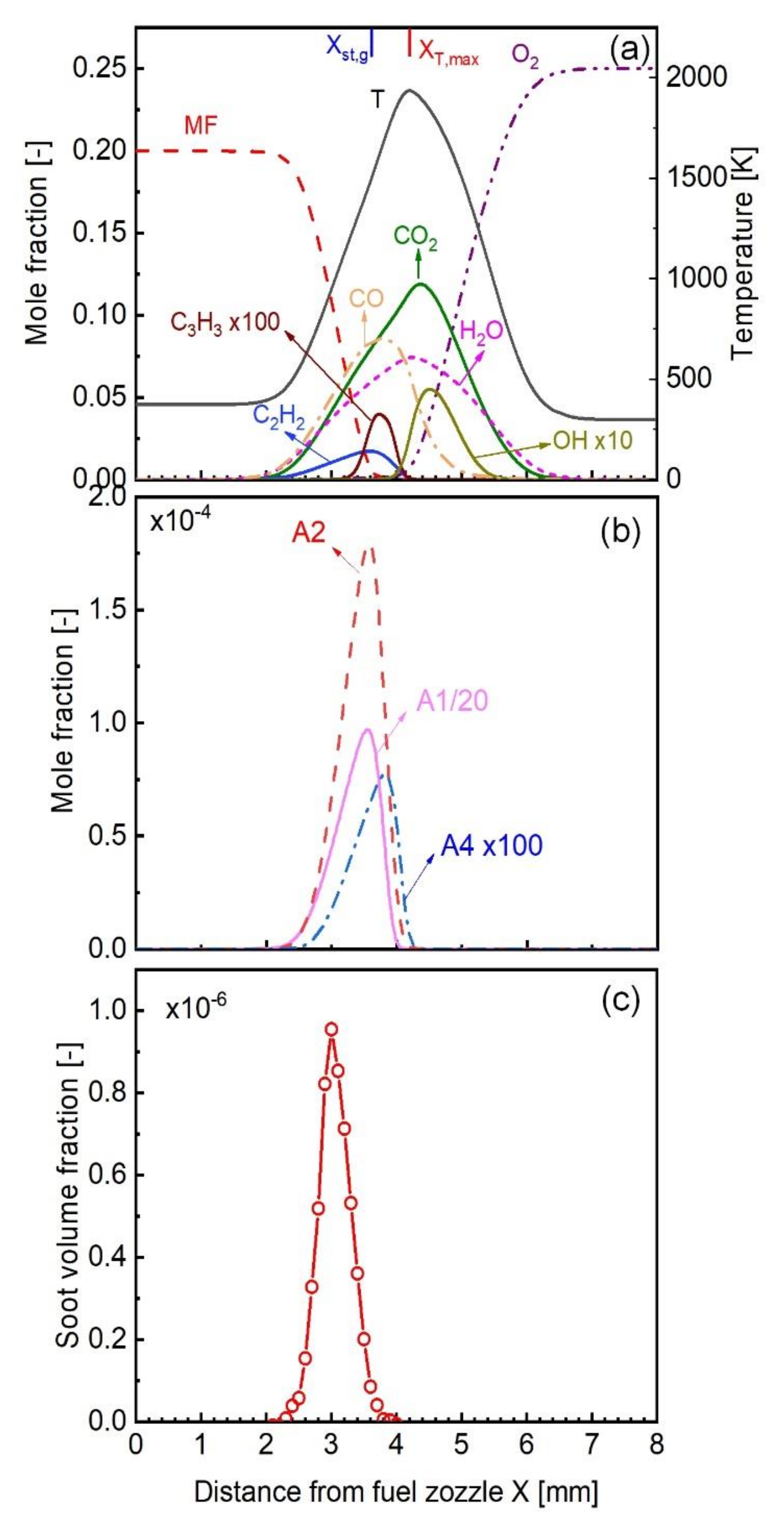
In order to better understand the sooting behavior of furans, we would like to firstly present the general flame and sooting zone structure of the present CDF flames. Figure 2a shows the axial profiles of the temperature and concentrations of major species for a neat MF flame (XF = 0.2 and XO = 0.25). As can be seen, the peak of the temperature profile, as an indicator of the flame sheet (marked as XT,max), is located at the distance of X = 4.2 mm (from the fuel nozzle); near the flame sheet, abundant OH and H radicals exist. Fuel pyrolysis occurs on the fuel side of the flame sheet, where large amounts of decomposed products such as C2H2 and C3H3 are presented. These small gaseous species also lead to the formation of benzene and PAHs such as naphthalene (A2) and pyrene (A4). Since PAHs are important soot precursors, soot nucleation will also take place on the fuel side of the flame (see Figure 2b). The formed nascent soot particles would be convected by the bulk flow towards the stagnation plane (where the axial gas velocity becomes zero, marked as Xst,g); during which, soot particles continue to grow up through various physiochemical process. After reaching a peak value near the stagnation plane, the soot particles would leak out due to their very low diffusivity, resulting in a drop of SVF near the stagnation plane (see Figure 2c).
It is also noticed that the overall SVF profile seems symmetric under the present XF/XO conditions. This situation is slightly different from the previous CDFs [44] (e.g., with XF = 1.0 and XO = 0.24), in which a skewed shape of the SVF profile (towards the fuel side) was observed. This is because the variations in the flame boundary conditions (XF/XO) will alter the relative location of the flame sheet to the stagnation plane, which, in turn, will notably affect the soot evolution process and result in different axial distributions of SVF. More details concerning the flame/soot zone structure of counterflow diffusion flames can be found in Reference [28].
Figure 3 replots the concentration profiles of the major species and PAHs in the mixture fraction space to provide an additional viewpoint of interpreting the present flame structure. As can be seen, the flame reaction sheet is located at Zst = 0.218, near which the flame temperature reaches the peak, and the oxygen and MF were almost consumed completely. The fuel-lean region at 0 < Z < Zst has abundant oxidizing species, such as OH, while the fuel-rich region corresponds to the area of Z > Zst, in which the fuel pyrolysis products (such as C2H2 and C3H3) and PAHs are largely present as a result of MF decomposition. In the following, we intend to plot the concentration of soot and soot precursors in the distance space for a more straightforward interpretation. Note that, since the focus of this work is to understand the relative maximum soot volume fractions and concentration of PAHs among different flames, the interpretation of the experimental/simulation results either in the mixture fraction space or in the physical distance space will be the same.

4.2. Experimental Results

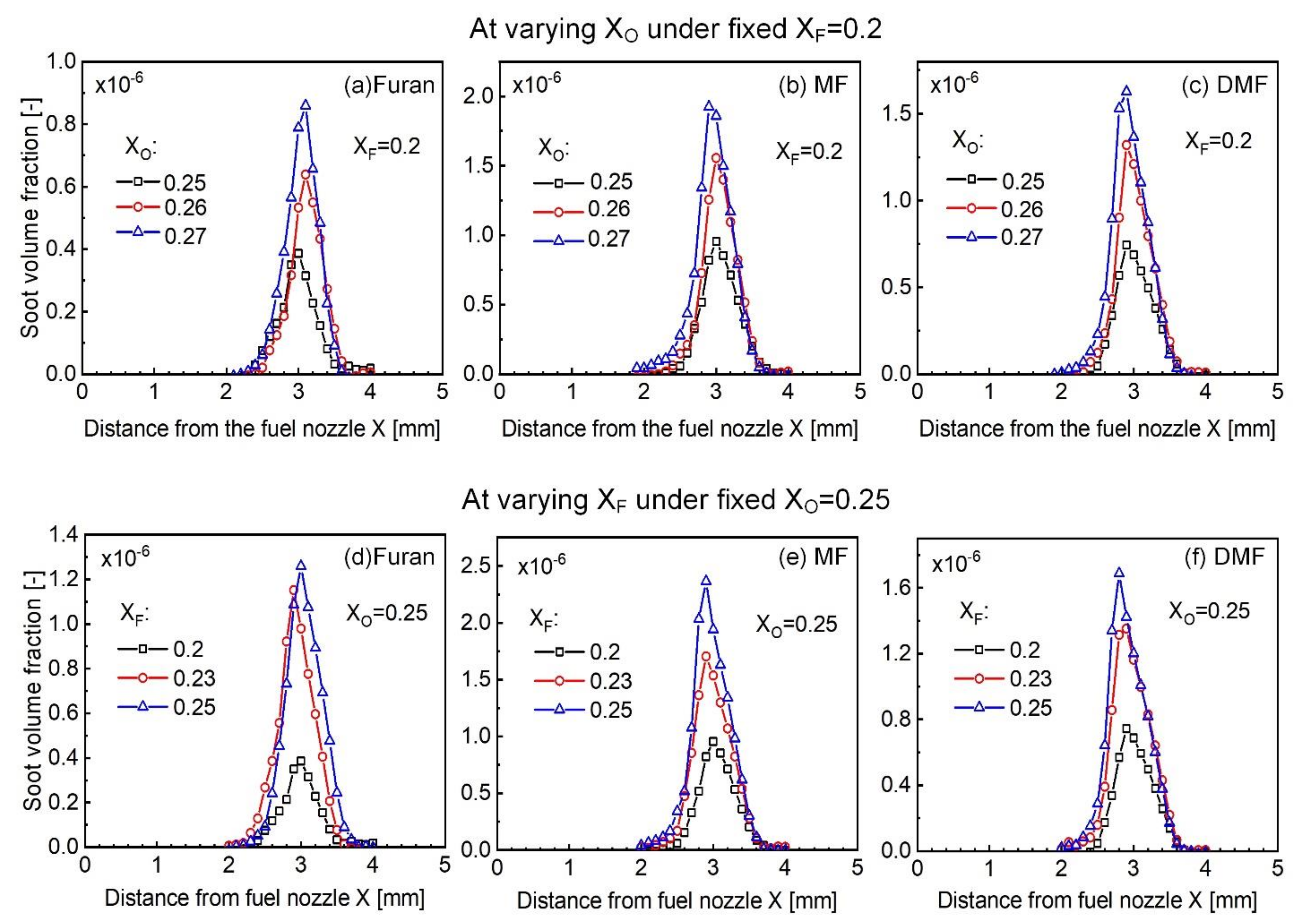
Figure 4 shows the measured axial profiles of SVF in furan, MF, and DMF flames under different oxygen concentrations and fuel stream conditions. For all the flames, a general consensus can be reached that, at a fixed XO, the maximum soot volume fraction increases monotonically with the increasing XF, which is easy to understand due to the increased fuel content and soot precursors formation. On the other hand, at a fixed XF, the soot volume fractions will also increase monotonically with the increasing XO. This increasing trend of SVF with XO in the present SF flames is consistent with a previous works [28]; the reasoning was generally attributed to an increased flame temperature at a higher XO, which, in turn, enhance fuel pyrolysis and the formation of soot precursors. The measured SVF profiles in Figure 4 are expected to serve as a reliable dataset for model validation and refinement.
In order to clearly illustrate the sooting propensity of the tested furans, the maximum SVFs of different furan flames were replotted and compared under the identical conditions of Xo = 0.25 and XF = 0.2 in Figure 5. Note that the relative sooting tendencies of these furan flames is the same regardless of the XO condition. As shown, furan has the lowest SVF among the three furanic biofuels, which is in agreement with the literature results. On the other hand, the present MF flame is found to produce more soot than DMF (e.g., the maximum SVF of the MF flame is 1.28 times higher than that of DMF at XF = 0.2 and XO = 0.25); this trend seems to be different from the premixed flame-based conclusions [19,20], in which DMF was seen to have a stronger tendency to form benzene and PAH precursors than MF. Such discrepancies may be caused by the different combustion environments (premixed or non-premixed flame). In the following section, detailed kinetic analyses were performed to provide chemical insights into the observed sooting tendencies of different furan flames in this work.

4.3. Kinetic Analysis

We firstly present the modeling results of PAHs for the furan, MF, and DMF flames in Figure 6, where the mole fraction of several represented aromatics of benzene (A1), naphthalene (A2), phenanthrene (A3), and pyrene (A4) are shown at the cases of XF = 0.2 and XO = 0.25. Note that the simulation results in the relative ranking of the PAH concentrations among the three furanic fuels is independent of the XO or XF conditions. As can be seen, furan flames produce the least amount of A1 and large PAHs (including A2, A3, and A4); this trend is consistent with that of the measured SVFs. On the other hand, while the DMF flame has a comparative mole fraction of A1 with a MF flame, the computed mole fraction of large PAHs is notably smaller in a DMF flame as compared to that of a MF flame. In consideration of the critical roles of PAHs played in soot nucleation [45], the simulation results of the PAH may reasonably explain that why the present MF flame is sootier than the DMF flame.
In order to further understand the relative PAH/soot formation tendency among furan, MF, and DMF flame, we performed rate of production (ROP) analyses to obtain the major fuel-specific decomposition pathways and the formation of important decomposed products. The result is shown in Figure 7. As can be seen, furan is mainly consumed by the H-addition at the C2 position of furan, forming radical species of C4H5O-3 and CH2CHCHCHO. The latter is then primarily consumed by isomerization to form the CH3CHCHCO radical, which is then converted to the CH3CHCH radical (by an elimination of CO) and, eventually, to C2H2. On the other hand, the decomposition of MF is initiated primarily by H-abstraction reactions, which mainly leads to the formation of vinylacetylene (C4H4) via the intermediate of 2-furanylmethyl. In addition, the H-abstraction of MF also produces the radical CH2CHCHCO, which then converts to C3H3. In contrast, the most important consumption channel for DMF is the H-abstraction to yield the resonance-stabilized 5-methyl-2-furanyl-methyl radical, which then produces phenol (C6H5OH) and 1,3-cyclopentadiene (C5H6) via a series of intermediate reactions. Another major pathway of DMF decomposition is to form the intermediate species of MF and the product of the C4 species. As will be shown later, the fuel-specific decomposed products play critical roles in determining the relative sooting tendency.
Supporting the reaction pathway analyses, the concentration of several important intermediate products during the decomposition of furan, MF, and DMF are shown in Figure 8. As can be seen, furan flame has the least amount of (a) C3H3, (b) C6H5, (c) C4H4, and (d) C6H5OH concentrations. As will be detailed later, these species are important precursors of benzene formation and PAH growth. This can be the reason for the lower soot production in furan flame compared to MF and DMF flames. When comparing MF and DMF, it shows that MF has more C3H3 and C6H5 while DMF flame has higher amounts of C4H4 and C6H5OH, due to the different fuel composition pathways. Such differences will eventually lead to different soot productions in MF and DMF flames.
Considering that benzene (A1) formation is a critical step towards the growth of large PAHs and soot formation, we firstly examined the reason for the different production rates of A1 in furan, MF, and DMF flames. By performing a rate of production (ROP) analysis, the most important benzene formation reactions were identified and shown in Figure 9. Moreover, to quantify the relative importance of each of these reactions, their percentage contributions to the A1 production rate were determined and normalized to the value of the total A1 production rate in furan flame, according to the computational approach specified in Reference [46]. The results in Figure 9 showed that A1 formation in furan is driven primarily by the self-recombination reaction of propargyl (C3H3), followed by the addition of C2H2 to the species C4H5-2 (CH3–C≡C–CH2•) and by the conversion of C6H5. The total A1 formation rate of furan is smaller than MF and DMF, which is in agreement with the mole fraction of A1 in Figure 6.
The amount of benzene produced in DMF and MF flames is quantitatively similar. On the one hand, MF produces larger amounts of benzene via the self-recombination of C3H3 and the conversion from C6H5 via the reactions of A1 + OH = C6H5 + H2O and MF + C6H5 = MF22J + A1 than DMF does, due to the higher concentrations of C3H3 and C6H5 radicals in MF flames. However, MF flame has a smaller benzene formation rate than DMF flame in terms of the H-addition reaction of C6H5OH: A1 + OH = C6H5OH + H and the reaction C4H5-2 + C2H2 = A1 + H, due to the higher amounts of C6H5OH and C4H5-2 formed during DMF combustion. The net result is that the total A1 production rate and the A1 concentration in MF flame is close to the value in DMF flame. Since the similar A1 formation trend between MF and DMF flames may not fully explain the higher sooting propensity of MF flame, we continue to examine the formation chemistry of large PAHs.
Figure 10 shows the dominating reaction channels of the A2 formations, as well as their respective contributions to the total A2 production. It shows that the dominant A2 formation reactions are similar among the tested furan, MF, and DMF flames; they are the reaction of H with aryl radicals (A2-1 and A2-2) produced from A1 via the sequential H-abstraction and C2H2 adding reaction, i.e., the well-known HACA scheme [47,48]. In addition, the combination of C6H5 with C4H4 and the com-bination of benzyl (C6H5CH2) and C3H3 radicals also play a role in A2 production. However, the rate of these A2 production reactions vary significantly in furan, MF, and DMF flames. As expected, furan flame has the smallest total A2 reaction rate and the individual formation rate compared to DMF and MF flames, due to its much lower concentration of A2 precursors such as A1, C6H5, and C4H4.
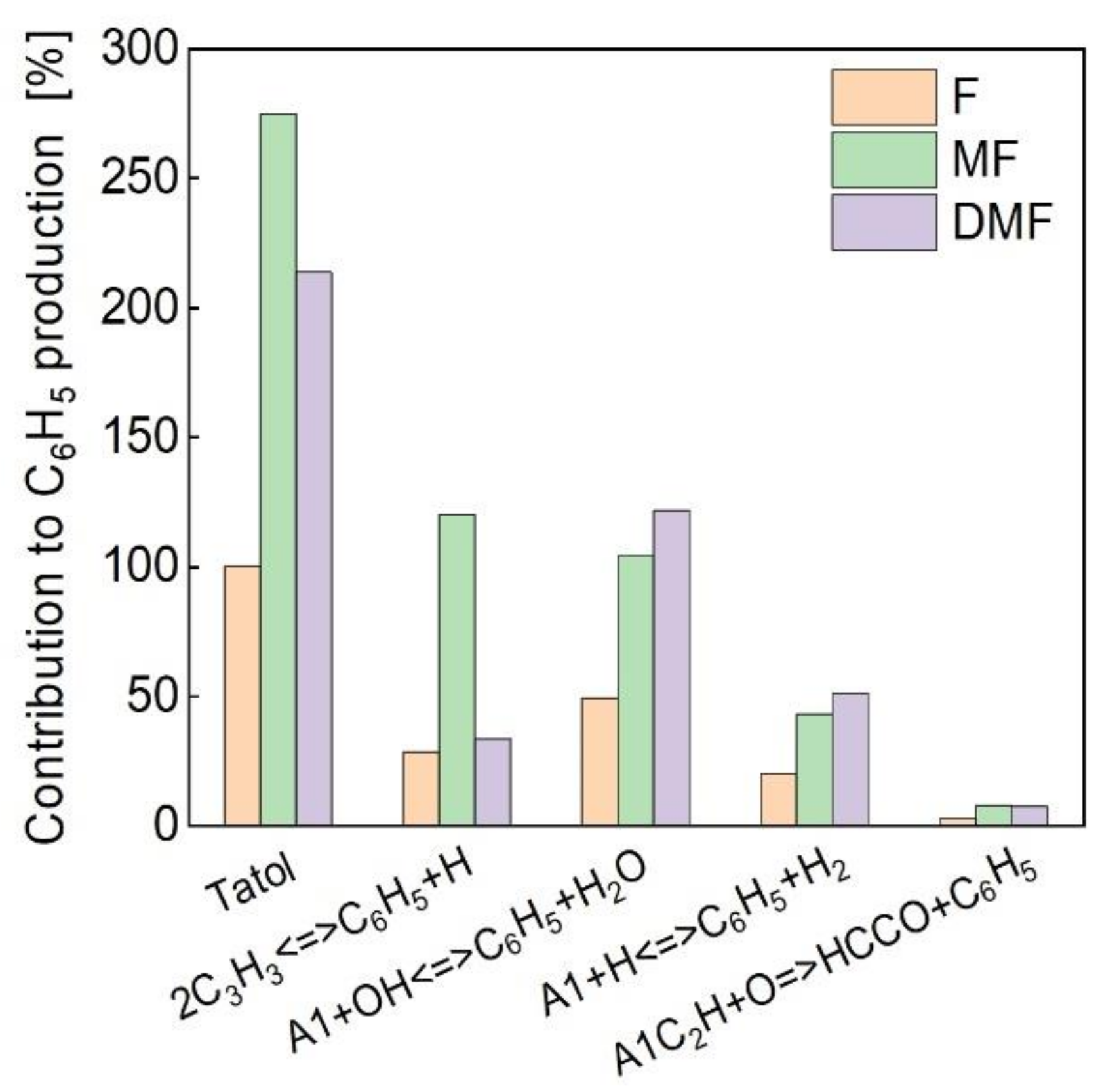
While the A1 concentration is similar in DMF and MF, the A2 concentration and the total A2 production rate is evidently higher in MF flame than in DMF flame. The reason can be derived from the results in Figure 11. It clearly shows that higher amounts of A2 in MF flame (than DMF flame) mainly come from the reaction of C6H5 with C4H4, followed by the HACA reactions, which can be traced back to the higher concentration of C6H5 in MF flame. Further ROP analyses on C6H5 (see Figure 11) showed that the higher amounts of C6H5 in MF originate from the reaction of 2C3H3 = C6H5 + H, whose contribution to C6H5 is significantly higher in MF flame than that of DMF flame. As a matter of fact, in DMF flame, the reverse reaction of 2C3H3 = C6H5 + H becomes dominant over the forward reaction, leading to a notable consumption of C6H5, while, in MF flame, the production of C6H5 via the reaction 2C3H3 = C6H5 + H is prevalent. As a result, the concentration of C6H5 in MF flame is higher, which, in turn, contributes to its larger concentration of A2 than DMF.
The further growth of PAH beyond A2 is mainly governed by the HACA growth reactions. Since MF flame produces more amounts of A2 than DMF does, a higher concentration of larger PAHs (such as A4) in MF flame can be easily understood. Since PAHs are known as important soot precursors, the relative concentration level of PAHs among the furan flames is likely to propagate the soot formation tendency.

5. Conclusions

In the present study, combined soot measurements and numerical simulations were performed to investigate the sooting behavior of several typical furanic biofuels, i.e., furan, 2-methylfuran (MF), and 2,5-dimethylfuran (DMF), in laminar counterflow diffusion flames. The relative sooting tendency of these furans was highlighted and was understood with the help of detailed kinetic analyses. The experimental results showed that, at identical flame boundary conditions, furan has the lowest soot volume fraction among the three fuels, which was consistent with the literature results. MF was found to produce the most amount of soot, which was higher than DMF under the present counterflow flames.
A new kinetic mechanism by coupling the combustion chemistry of furans and PAH growth was constructed to perform numerical analyses. Being consistent with the measured sooting tendency trend of furan < DMF < MF, the simulation results also showed that MF has the strongest propensity to form PAH. A kinetic analysis showed that MF decomposition produces large amounts of C3 species, which are efficient precursors of benzene and PAH. In contrast, DMF combustion mainly leads to the formation of phenol; however, the subsequent conversion of phenol to PAHs seems to be less efficient than the C3H3-induced pathways in the MF flame. This may explain the smaller soot production in the present DMF flame than that of the MF flame.

Author Contributions

Investigation, Q.M. and L.X.; methodology, J.Z.; project administration, F.Y.; software, Q.M. and J.Z.; supervision, F.Y. and Y.W.; and writing—original draft, Q.M.; writing—review and editing, L.X. and Y.W. All authors have read and agreed to the published version of the manuscript.

Funding

This work was supported by the National Natural Science Foundation of China (51976142) and the Hubei Key Laboratory of Advanced Technology for Automotive Components (XDQCKF2021003).

Conflicts of Interest

The authors declare no conflict of interest.

References

  1. Kohse-Höinghaus, K. Combustion in the future: The importance of chemistry. Proc. Combust. Inst. 2021, 38, 1–56. [Google Scholar] [CrossRef]
  2. Xu, H.; Wang, C.; Ma, X.; Sarangi, A.K.; Weall, A.; Krueger-Venus, J. Fuel injector deposits in direct-injection spark-ignition engines. Prog. Energy Combust. Sci. 2015, 50, 63–80. [Google Scholar] [CrossRef]
  3. Bond, T.C.; Doherty, S.J.; Fahey, D.W.; Forster, P.M.; Berntsen, T.; Deangelo, B.J.; Flanner, M.G.; Ghan, S.; Kärcher, B.; Koch, D. Bounding the role of black carbon in the climate system: A scientific assessment. J. Geophys. Res. Atmos. 2013, 118, 5380–5552. [Google Scholar] [CrossRef]
  4. Kennedy, I.M. The health effects of combustion-generated aerosols. Proc. Combust. Inst. 2007, 31, 2757–2770. [Google Scholar] [CrossRef]
  5. Román-Leshkov, Y.; Barrett, C.J.; Liu, Z.Y.; Dumesic, J.A. Production of dimethylfuran for liquid fuels from biomass-derived carbohydrates. Nature 2007, 447, 982–985. [Google Scholar] [CrossRef] [PubMed]
  6. Saha, B.; Abu-Omar, M.M. Current Technologies, Economics, and Perspectives for 2,5-Dimethylfuran Production from Biomass-Derived Intermediates. ChemSusChem 2015, 8, 1133–1142. [Google Scholar] [CrossRef]
  7. Xu, N.; Gong, J.; Huang, Z. Review on the production methods and fundamental combustion characteristics of furan derivatives. Renew. Sustain. Energy Rev. 2016, 54, 1189–1211. [Google Scholar] [CrossRef]
  8. Wang, H.; Zhu, C.; Li, D.; Liu, Q.; Tan, J.; Wang, C.; Cai, C.; Ma, L. Recent advances in catalytic conversion of biomass to 5-hydroxymethylfurfural and 2, 5-dimethylfuran. Renew. Sustain. Energy Rev. 2019, 103, 227–247. [Google Scholar] [CrossRef]
  9. Tuan Hoang, A.; Viet Pham, V. 2-Methylfuran (MF) as a potential biofuel: A thorough review on the production pathway from biomass, combustion progress, and application in engines. Renew. Sustain. Energy Rev. 2021, 148, 111265. [Google Scholar] [CrossRef]
  10. Alexandrino, K. Comprehensive Review of the Impact of 2,5-Dimethylfuran and 2-Methylfuran on Soot Emissions: Experiments in Diesel Engines and at Laboratory-Scale. Energy Fuels 2020, 34, 6598–6623. [Google Scholar] [CrossRef]
  11. Chen, G.; Shen, Y.; Zhang, Q.; Yao, M.; Zheng, Z.; Liu, H. Experimental study on combustion and emission characteristics of a diesel engine fueled with 2,5-dimethylfuran–diesel, n-butanol–diesel and Gasoline–Diesel blends. Energy 2013, 54, 333–342. [Google Scholar] [CrossRef]
  12. Zhong, S.; Daniel, R.; Xu, H.; Zhang, J.; Turner, D.; Wyszynski, M.L.; Richards, P. Combustion and Emissions of 2,5-Dimethylfuran in a Direct-Injection Spark-Ignition Engine. Energy Fuels 2010, 24, 2891–2899. [Google Scholar] [CrossRef]
  13. Zheng, Z.; Wang, X.; Zhong, X.; Hu, B.; Liu, H.; Yao, M. Experimental study on the combustion and emissions fueling biodiesel/n-butanol, biodiesel/ethanol and biodiesel/2,5-dimethylfuran on a diesel engine. Energy 2016, 115, 539–549. [Google Scholar] [CrossRef]
  14. Michelsen, H.A. Probing soot formation, chemical and physical evolution, and oxidation: A review of in situ diagnostic techniques and needs. Proc. Combust. Inst. 2017, 36, 717–735. [Google Scholar] [CrossRef] [Green Version]
  15. Wang, Y.; Chung, S.H. Soot formation in laminar counterflow flames. Prog. Energy Combust. Sci. 2019, 74, 152–238. [Google Scholar] [CrossRef]
  16. Alexandrino, K.; Baena, C.; Millera, Á.; Bilbao, R.; Alzueta, M.U. 2-methylfuran pyrolysis: Gas-phase modelling and soot formation. Combust. Flame 2018, 188, 376–387. [Google Scholar] [CrossRef]
  17. Cheng, Z.; Xing, L.; Zeng, M.; Dong, W.; Zhang, F.; Qi, F.; Li, Y. Experimental and kinetic modeling study of 2,5-dimethylfuran pyrolysis at various pressures. Combust. Flame 2014, 161, 2496–2511. [Google Scholar] [CrossRef]
  18. Alexandrino, K.; Millera, Á.; Bilbao, R.; Alzueta, M.U. Novel aspects in the pyrolysis and oxidation of 2,5-dimethylfuran. Proc. Combust. Inst. 2015, 35, 1717–1725. [Google Scholar] [CrossRef]
  19. Togbé, C.; Tran, L.-S.; Liu, D.; Felsmann, D.; Oßwald, P.; Glaude, P.-A.; Sirjean, B.; Fournet, R.; Battin-Leclerc, F.; Kohse-Höinghaus, K. Combustion chemistry and flame structure of furan group biofuels using molecular-beam mass spectrometry and gas Chromatography—Part III: 2,5-Dimethylfuran. Combust. Flame 2014, 161, 780–797. [Google Scholar] [CrossRef] [Green Version]
  20. Tran, L.-S.; Sirjean, B.; Glaude, P.-A.; Kohse-Höinghaus, K.; Battin-Leclerc, F. Influence of substituted furans on the formation of Polycyclic Aromatic Hydrocarbons in flames. Proc. Combust. Inst. 2015, 35, 1735–1743. [Google Scholar] [CrossRef]
  21. Cheng, Z.; He, S.; Xing, L.; Wei, L.; Li, W.; Li, T.; Yan, B.; Ma, W.; Chen, G. Experimental and Kinetic Modeling Study of 2-Methylfuran Pyrolysis at Low and Atmospheric Pressures. Energy Fuels 2017, 31, 896–903. [Google Scholar] [CrossRef]
  22. Liu, H.; Zhang, P.; Liu, X.; Chen, B.; Geng, C.; Li, B.; Wang, H.; Li, Z.; Yao, M. Laser diagnostics and chemical kinetic analysis of PAHs and soot in co-flow partially premixed flames using diesel surrogate and oxygenated additives of n -butanol and DMF. Combust. Flame 2018, 188, 129–141. [Google Scholar] [CrossRef]
  23. Conturso, M.; Sirignano, M.; D’Anna, A. Effect of 2,5-dimethylfuran doping on particle size distributions measured in premixed ethylene/air flames. Proc. Combust. Inst. 2017, 36, 985–992. [Google Scholar] [CrossRef]
  24. Conturso, M.; Sirignano, M.; D’Anna, A. Effect of furanic biofuels on particles formation in premixed Ethylene–Air flames: An experimental study. Fuel 2016, 175, 137–145. [Google Scholar] [CrossRef]
  25. Sirignano, M.; Conturso, M.; D’Anna, A. Effect of furans on particle formation in diffusion flames: An experimental and modeling study. Proc. Combust. Inst. 2015, 35, 525–532. [Google Scholar] [CrossRef]
  26. Chu, H.; Ya, Y.; Nie, X.; Qiao, F.; Jiaqiang, E. Effects of adding cyclohexane, n-hexane, ethanol, and 2,5-dimethylfuran to fuel on soot formation in laminar coflow n-heptane/iso-octane diffusion flame. Combust. Flame 2021, 225, 120–135. [Google Scholar] [CrossRef]
  27. Chu, H.; Ya, Y.; Nie, X.; Zhou, Y.; Hu, J.; Dong, S.; Jiaqiang, E. Effects of ethanol and 2, 5-dimethylfuran addition on the morphology and nanostructure evolution of soot in gasoline primary reference fuel-air coflow diffusion flames. Fuel 2020, 281, 118711. [Google Scholar] [CrossRef]
  28. Xu, L.; Yan, F.; Zhou, M.; Wang, Y.; Chung, S.H. Experimental and soot modeling studies of ethylene counterflow diffusion flames: Non-monotonic influence of the oxidizer composition on soot formation. Combust. Flame 2018, 197, 304–318. [Google Scholar] [CrossRef]
  29. Yan, F.; Zhou, M.; Xu, L.; Wang, Y.; Chung, S.H. An experimental study on the spectral dependence of light extinction in sooting ethylene counterflow diffusion flames. Exp. Therm. Fluid Sci. 2019, 100, 259–270. [Google Scholar] [CrossRef] [Green Version]
  30. Yi, X.; Lee, C.F.F. Forward-illumination light-extinction technique for soot measurement. Appl. Opt. 2006, 45, 2046–2057. [Google Scholar]
  31. Xu, Y.; Lee, C. Study of Soot Formation of Oxygenated Diesel Fuels Using Forward Illumination Light Extinction (FILE) Technique. SAE Tech. Pap. 2006. [Google Scholar] [CrossRef]
  32. Bi, L.; Yang, P.; Kattawar, G.W. Edge-effect contribution to the extinction of light by dielectric disks and cylindrical particles. Appl. Opt. 2010, 49, 4641–4646. [Google Scholar] [CrossRef]
  33. Santoro, R.J.; Semerjian, H.G.; Dobbins, R.A. Soot particle measurements in diffusion flames. Combust. Flame 1983, 51, 203–218. [Google Scholar] [CrossRef]
  34. Eremin, A.; Gurentsov, E.; Popova, E.; Priemchenko, K. Size dependence of complex refractive index function of growing nanoparticles. Appl. Phys. B 2011, 104, 285–295. [Google Scholar] [CrossRef]
  35. Krishnan, S.S.; Lin, K.-C.; Faeth, G.M. Extinction and Scattering Properties of Soot Emitted From Buoyant Turbulent Diffusion Flames. J. Heat Trans. 2000, 123, 331–339. [Google Scholar] [CrossRef]
  36. Diego, C.P.R.D.S. CHEMKIN-PRO 15131; Reaction Design: San Diego, CA, USA, 2011. [Google Scholar]
  37. Somers, K.P.; Simmie, J.M.; Metcalfe, W.K.; Curran, H.J. The pyrolysis of 2-methylfuran: A quantum chemical, statistical rate theory and kinetic modelling study. Phys. Chem. Chem. Phys. 2014, 16, 5349–5367. [Google Scholar] [CrossRef] [Green Version]
  38. Somers, K.P.; Simmie, J.M.; Gillespie, F.; Conroy, C.; Black, G.; Metcalfe, W.K.; Battin-Leclerc, F.; Dirrenberger, P.; Herbinet, O.; Glaude, P.A.; et al. A comprehensive experimental and detailed chemical kinetic modelling study of 2,5-dimethylfuran pyrolysis and oxidation. Combust. Flame 2013, 160, 2291–2318. [Google Scholar] [CrossRef] [Green Version]
  39. Somers, K.P.; Simmie, J.M.; Gillespie, F.; Burke, U.; Connolly, J.; Metcalfe, W.K.; Battin-Leclerc, F.; Dirrenberger, P.; Herbinet, O.; Glaude, P.A.; et al. A high temperature and atmospheric pressure experimental and detailed chemical kinetic modelling study of 2-methyl furan oxidation. Proc. Combust. Inst. 2013, 34, 225–232. [Google Scholar] [CrossRef] [Green Version]
  40. Yu, W.; Raj, A.; Chung, S.H. A PAH growth mechanism and synergistic effect on PAH formation in counterflow diffusion flames. Combust. Flame 2013, 160, 1667–1676. [Google Scholar]
  41. Wang, J.; Sun, W.; Wang, G.; Fan, X.; Lee, Y.-Y.; Law, C.K.; Qi, F.; Yang, B. Understanding benzene formation pathways in pyrolysis of two C6H10 isomers: Cyclohexene and 1,5-hexadiene. Proc. Combust. Inst. 2019, 37, 1091–1098. [Google Scholar] [CrossRef]
  42. Hansen, N.; Kasper, T.; Yang, B.; Cool, T.A.; Li, W.; Westmoreland, P.R.; Oßwald, P.; Kohse-Höinghaus, K. Fuel-structure dependence of benzene formation processes in premixed flames fueled by C6H12 isomers. Proc. Combust. Inst. 2011, 33, 585–592. [Google Scholar] [CrossRef]
  43. Zhang, H.R.; Eddings, E.G.; Sarofim, A.F.; Westbrook, C.K. Fuel dependence of benzene pathways. Proc. Combust. Inst. 2009, 32, 377–385. [Google Scholar] [CrossRef]
  44. Xu, L.; Yan, F.; Wang, Y.; Chung, S.H. Chemical effects of hydrogen addition on soot formation in counterflow diffusion flames: Dependence on fuel type and oxidizer composition. Combust. Flame 2020, 213, 14–25. [Google Scholar] [CrossRef]
  45. Gleason, K.; Carbone, F.; Sumner, A.J.; Drollette, B.D.; Plata, D.L.; Gomez, A. Small aromatic hydrocarbons control the onset of soot nucleation. Combust. Flame 2021, 223, 398–406. [Google Scholar] [CrossRef]
  46. Yan, F.; Xu, L.; Wang, Y.; Park, S.; Sarathy, S.M.; Chung, S.H. On the opposing effects of methanol and ethanol addition on PAH and soot formation in ethylene counterflow diffusion flames. Combust. Flame 2019, 202, 228–242. [Google Scholar] [CrossRef]
  47. Frenklach, M. Reaction mechanism of soot formation in flames. Phys. Chem. Chem. Phys. 2002, 4, 2028–2037. [Google Scholar] [CrossRef]
  48. Frenklach, M.; Singh, R.I.; Mebel, A.M. On the low-temperature limit of HACA. Proc. Combust. Inst. 2019, 37, 969–976. [Google Scholar] [CrossRef]
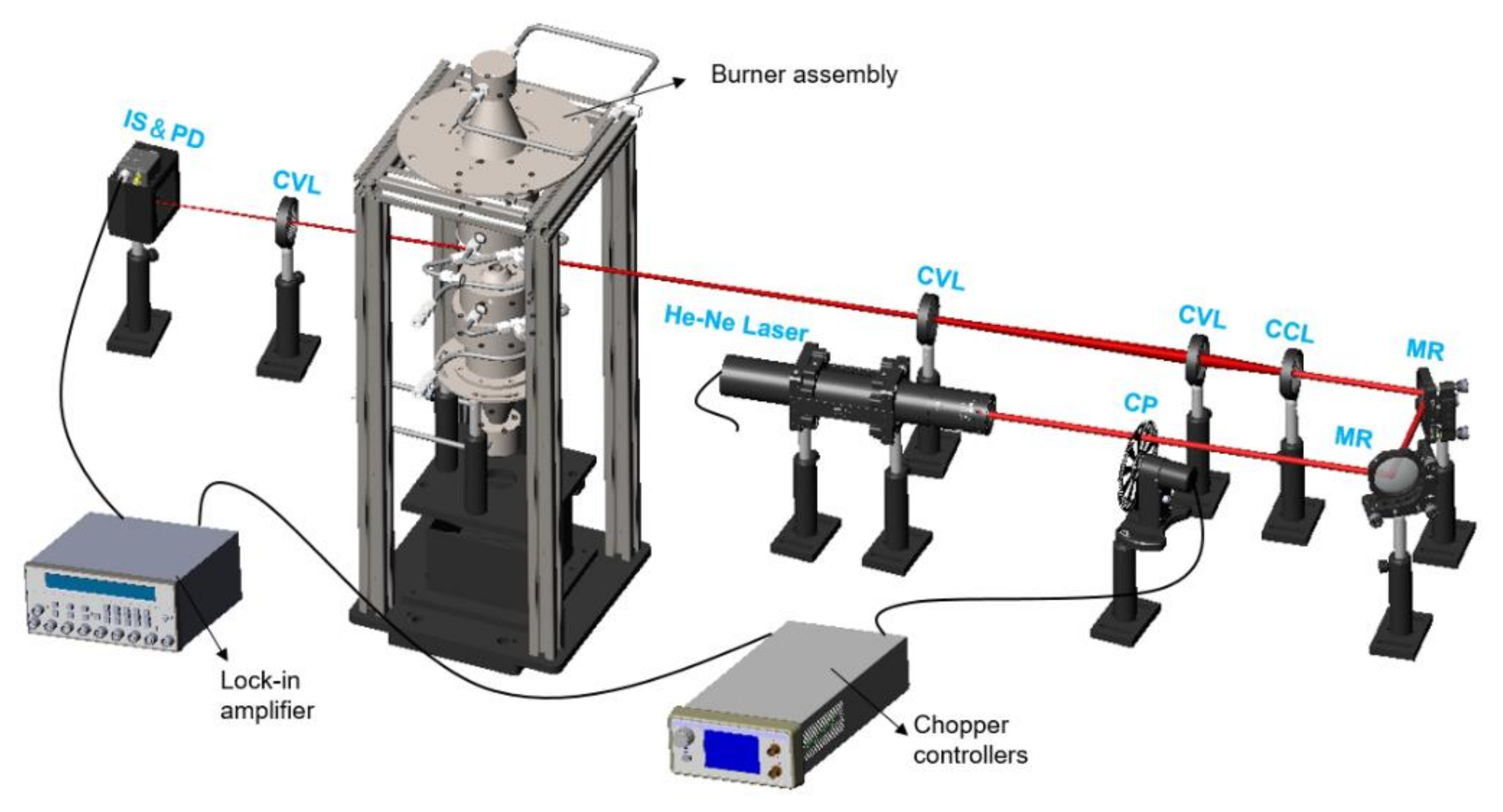
Figure 1. Schematic of the light extinction experimental setup. MR: silver mirror, CP: mechanical chopper, CCL: concave lens, CVL: convex lens, and IS & PD: integrating sphere and photodiode.
Energies 14 05995 g001
Figure 2. Computed flame structure of the (a) temperature profile, concentration of the intermediate species, and (b) aromatics species, as well as (c) the measured SVF profile for MF counterflow flames (XF = 0.2 and XO = 0.25).
Energies 14 05995 g002
Figure 3. Computed flame structure of the (a) temperature profile, concentration of major species, and (b) PAHs in the mixture fraction space.
Energies 14 05995 g003
Figure 4. Measured profiles of the soot volume fraction for furan, MF, and DMF counterflow flames at a fixed XF = 0.2 under varying XO conditions (upper panel) and at a fixed XO = 0.25 under varying XF conditions (lower panel).
Energies 14 05995 g004
Figure 5. Profiles of the soot volume fraction for furan, MF, and DMF performed at the conditions of XF = 0.2 and XO = 0.25.
Energies 14 05995 g005
Figure 6. Computed mole fractions of A1-A4 for furan, MF, and DMF flames.
Energies 14 05995 g006
Figure 7. Major fuel decomposition pathways and the formed decomposed products for furan, MF, and DMF.
Energies 14 05995 g007
Figure 8. Computed mole fractions of several important species, including (a) C3H3, (b) C6H5, (c) C4H4 and (d) C6H5OH during the combustion of furan, MF, and DMF.
Energies 14 05995 g008
Figure 9. Percentage contribution to the A1 production from each reaction for furan, MF, and DMF flames (XF = 0.2 and XO = 0.25). Here, MF22J is 2-furanylmethyl.
Energies 14 05995 g009
Figure 10. Percentage contribution from each reaction to A2 production for the furan, MF, and DMF flames.
Energies 14 05995 g010
Figure 11. Percentage contribution from each reaction to C6H5 production for the furan, MF, and DMF flames.
Energies 14 05995 g011
Table 1. Flame boundary conditions in this work. V is the fuel and oxidizer stream velocity, T is the temperature, and Zst is the stoichiometric mixture fraction.
SeriesFuel StreamOxidizer StreamZst
(F/MF/DMF)
F/MF/DMFN2V
(cm/s)
TO2N2V
(cm/s)
T
Base0.2/0.2/0.20.820373 K0.250.7520298 K0.256/0.218/0.193
Varying
XO
0.2/0.2/0.20.8200.260.74200.264/0.225/0.199
0.2/0.2/0.20.8200.270.73200.271/0.231/0.205
Varying XF0.23/0.23/0.230.77200.250.75200.237/0.202/0.179
0.25/0.25/0.250.75200.250.75200.226/0.193/0.171
Publisher’s Note: MDPI stays neutral with regard to jurisdictional claims in published maps and institutional affiliations.