
Design Optimization of Electrodynamic Structure of Permanent Magnet Piston Mechanical Electric Engine

Abstract
:1. Introduction
1.1. Research Motivation
1.2. Literature Review
1.3. Challenges and Problems
1.4. Contributions of This Work
- (1)
- The PMPMEE adopts the principle of reciprocating linear motion of the piston for machine-to-electric energy conversion, which couples a traditional internal combustion engine with a linear motor into a single unit to attain mechanical and electrical energy output without changing the engine size. This overcomes the problems of the existing piston internal combustion generator set electricity mixture electricity era, such as an unreasonable regular device, uncoordinated work, low conversion and transfer efficiency, power waste, etc.
- (2)
- Based on its structural principle, and the established gadget electricity demand model and electrodynamic model of the engine, the theoretical groundwork for subsequent research is given.
- (3)
- The rational design of the electrodynamic structure of the PMPMEE has a significant impact on the electric power output. In order to effectively reduce the internal electric power loss and improve the output power, an optimization model is established with the output power as the optimization target to optimize the design of the electrodynamic structure size of the engine, and the optimal structural dimensions are obtained.
- (4)
- Based on the optimization method integrated with finite element simulation and ISIGHT software, the NLPQL algorithm is used to analyze and optimize the electrodynamic structure of the engine. The optimization algorithm applies to nonlinear programming problems with multiple inequality constraints, and effectively avoids the disadvantage of the optimal set, and validates the validity of the optimization results by way of experiments.
1.5. Organization of the Paper
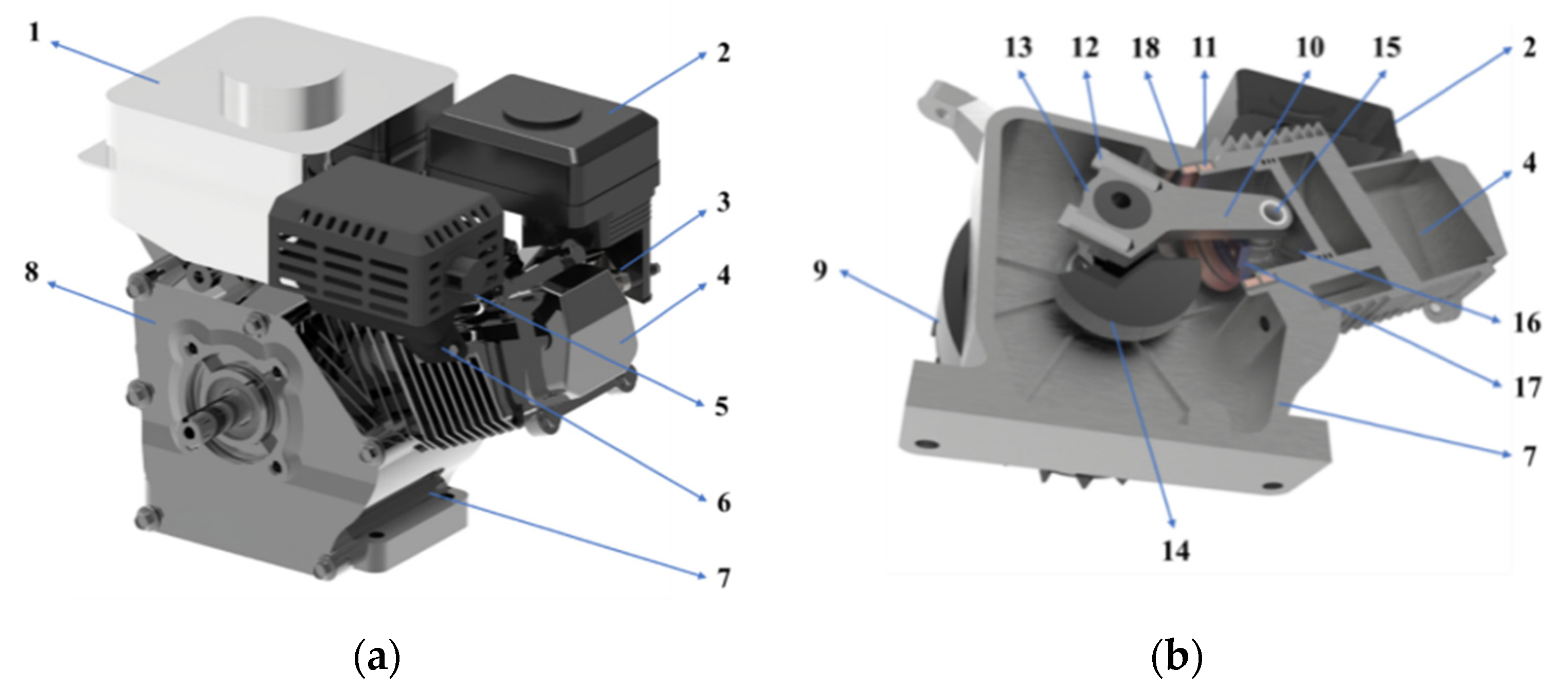
2. Structure and Principle of PMPMEE
3. Mathematical Model of PMPMEE
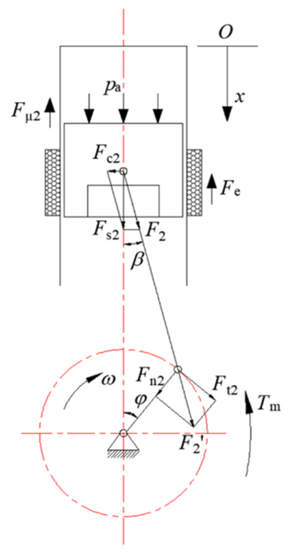
3.1. System Dynamics Model
3.2. Electrodynamic Model
4. Finite Element Simulation Analysis
4.1. No-Load Characteristics Analysis
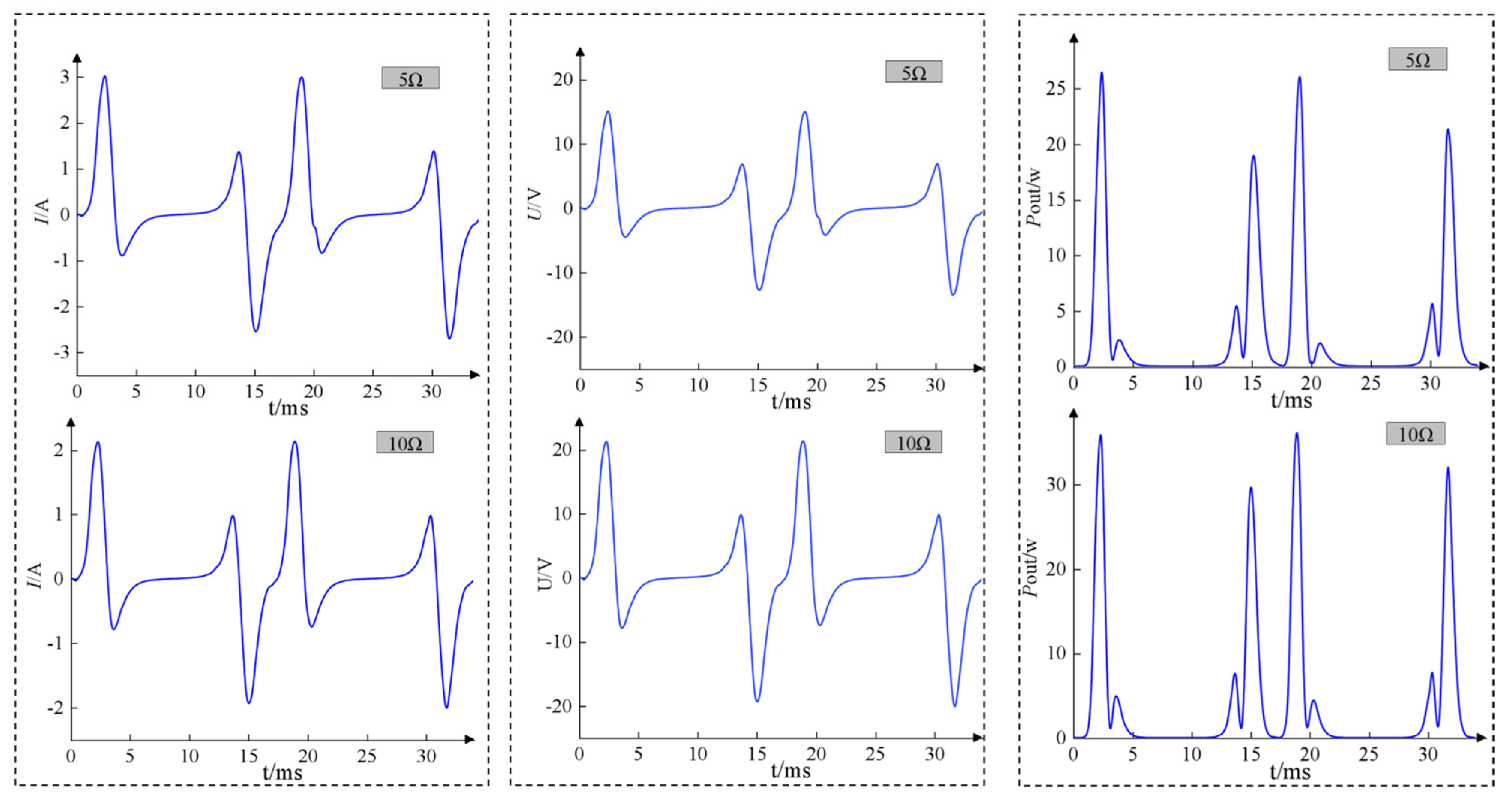
4.2. Load Characteristics Analysis
5. Optimization and Validation
5.1. Design Optimization Model
- (1)
- Optimization objectives
- (2)
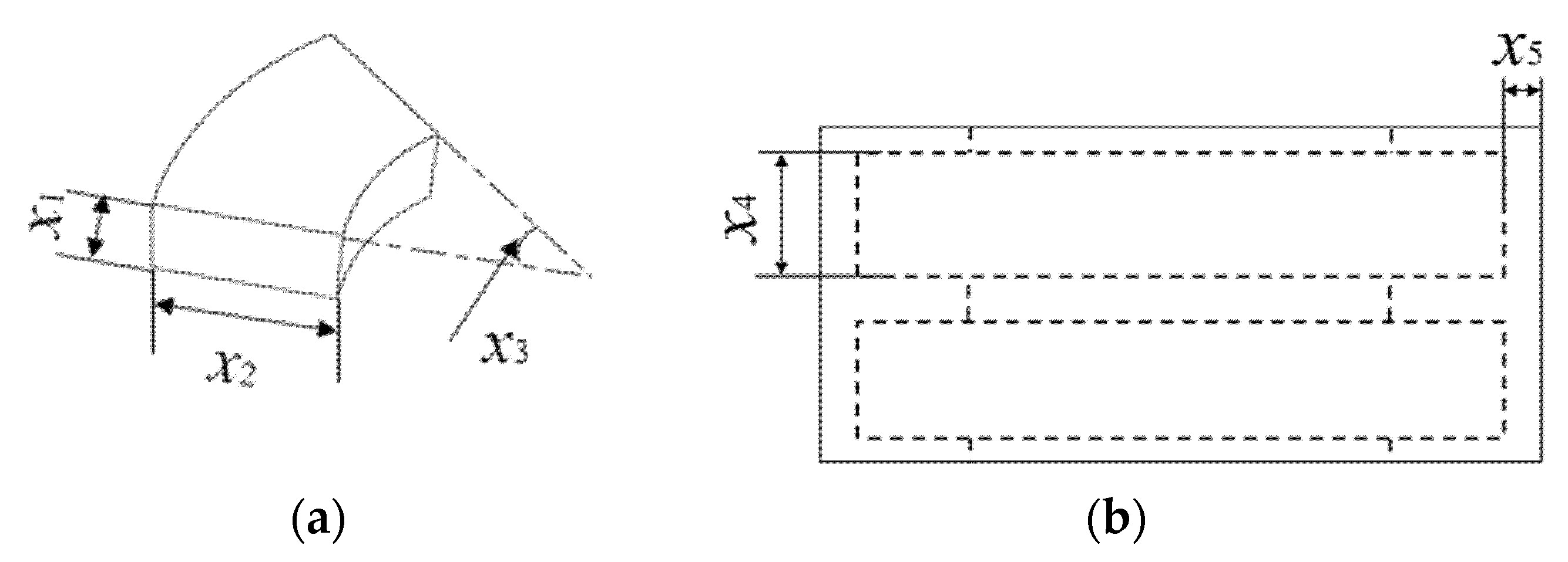
- Design variables
- (3)
- Constraints
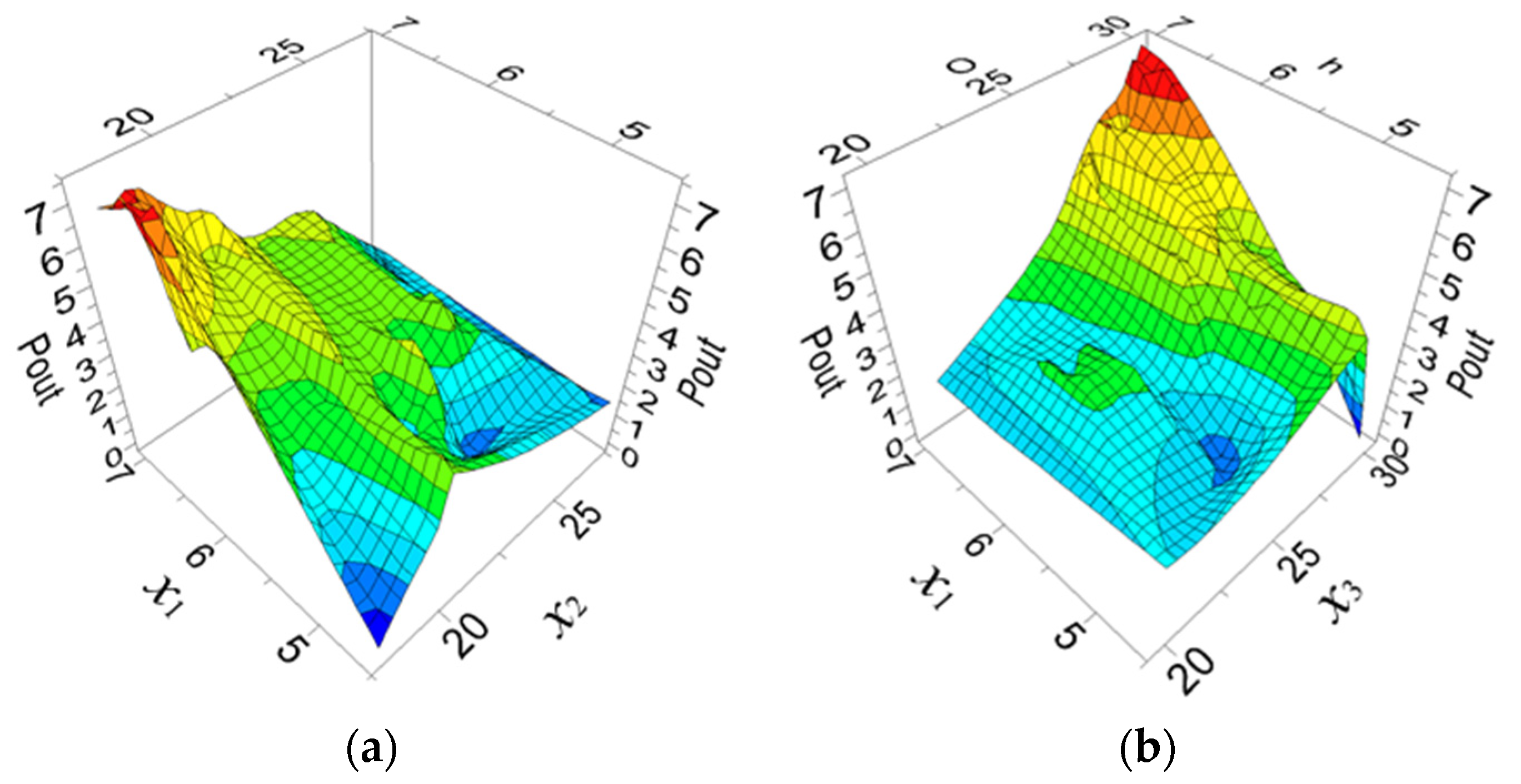
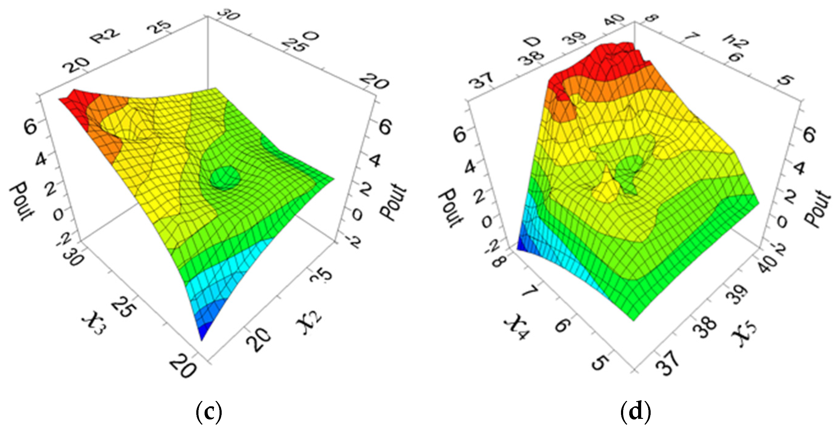
5.2. Optimization Results
6. Prototype Test
7. Conclusions
- (1)
- Based on the three-dimensional model, the study analyzed its working principle, established the system dynamics model and electrodynamic model, and derived the electrodynamic structure power expression to provide the theoretical basis for subsequent optimization studies.
- (2)
- The basic characteristics of the engine electrodynamic structure were investigated by using ANSOFT Maxwell software with a simplified 3D finite element model. Finite elements verified the theoretical analysis, and the magnetic chain, counter potential, output current, voltage, and power waveforms of the electrodynamic structure were obtained. The no-load and load characteristic laws of the electrodynamic structure were further analyzed.
- (3)
- An optimization method integrating finite element and NLPQL optimization algorithms is proposed, which effectively improves the output power of the electrodynamic structure of the PMPMEE. The output power of the electrodynamic part of the engine is increased to 8.40 w after optimization, which is 18.81% higher than that before optimization. The electromagnetic performance of the engine is improved effectively, verifying the effectiveness of the optimization method.
- (4)
- A test prototype was designed based on the 168 F gasoline engine. The test obtained the transient change pattern of the engine load voltage, which is consistent with the simulation results, verifying the principle and performance of the new structure engine.
Author Contributions
Funding
Institutional Review Board Statement
Informed Consent Statement
Data Availability Statement
Conflicts of Interest
Nomenclature
| r | The crank radius |
| l | The connecting rod length |
| λ | The crank connecting rod |
| φ | The crankshaft turning angle |
| ω | The angular velocity of the crankshaft |
| α | The angular acceleration of the crankshaft |
| Fa | The thrust force of gas combustion acting on the piston |
| Fj | The reciprocating inertia force |
| Fe | The electromagnetic force on the kinetic subassembly |
| Fμ | The friction force between the piston ring and the cylinder liner |
| Fs | The piston force |
| nr | The rated speed |
| Tm | The resistance torque of the external mechanical load |
| Tfri | The friction torque generated by the connecting rod to the crank pin |
| Tfbi | The friction torque generated by the bearing to the spindle |
| ψ | The single-phase fundamental magnetic chain |
| Φ | The per-pole flux function |
| N | The total number of turns of the single-phase coil |
| τ | The pole pitch of the permanent magnet |
| vT | The average velocity per unit cycle |
| xT | The displacement per unit cycle |
| s | The stroke of the piston |
| vT | The average velocity per unit cycle |
| xT | The displacement per unit cycle |
| s | The stroke of the piston |
| T | The engine crankshaft rotation time of two weeks |
| f | The electromagnetic frequency |
| Φm | The magnitude of magnetic flux per pole |
| Ph | The hysteresis loss |
| Pec | The eddy current loss |
| Kh | The hysteresis loss coefficient |
| Bm | The magnetic density |
| σ | The core material conductivity |
| C | The capacitance |
| R | The resistance |
| L | The inductors |
| d | The search direction |
| Bk | The Newton-like matrix |
| f (x) | The objective function |
| ∇f (x) | The gradient of the objective function |
| gj (x) | The constraint function |
| ∇gj (x) | The gradient of the constraint function |
| xu | The upper bound of the boundary constraint |
| j | The variable |
Abbreviations
| PMPMEE | Permanent magnet piston mechanical electric engine |
| FPE-LG | Free piston expander-linear generator |
| ORC | Organic Rankine cycle |
| CAE | Computer aided engineering |
| ECPE | Electric power confined piston engine |
References
- Wang, X.; Chen, F.; Zhu, R. A Review of the Design and Control of Free-Piston Linear Generator. Energies 2018, 11, 2179. [Google Scholar] [CrossRef] [Green Version]
- Zare, S.; Tavakolpour-Saleh, A. Free piston Stirling engines: A review. Int. J. Energy Res. 2020, 44, 5039–5070. [Google Scholar] [CrossRef]
- Zhang, Z.; Luo, M.; Duan, J.; Kou, B. Performance Analysis of Double-Sided Permanent Magnet Linear Synchronous Motor with Quasi-sinusoidal Ring Windings. IEEE Trans. Energy Convers. 2020, 35, 1465–1474. [Google Scholar] [CrossRef]
- Tan, Q.; Wang, M.; Li, L. Analysis of a New Flux Switching Permanent Magnet Linear Motor. IEEE Trans. Magn. 2021, 57, 1–5. [Google Scholar] [CrossRef]
- Hong, J.; Wang, Z.; Yao, Y. Fault prognosis of battery system based on accurate voltage abnormity prognosis using long short-term memory neural networks. Appl. Energy 2019, 251, 113381. [Google Scholar] [CrossRef]
- Hong, J.; Wang, Z.; Ma, F. Thermal Runaway Prognosis of Battery Systems Using the Modified Multi-Scale Entropy in Real-World Electric Vehicles. IEEE Trans. Transp. Electrif. 2021. [Google Scholar] [CrossRef]
- Abdollahi, S.; Mirzayee, M.; Mirsalim, M. Design and Analysis of a Double-Sided Linear Induction Motor for Transportation. IEEE Trans. Magn. 2015, 51, 1–7. [Google Scholar] [CrossRef]
- Baatar, N.; Yoon, H.; Pham, M. Shape Optimal Design of a 9-pole 10-slot PMLSM for Detent Force Reduction Using Adaptive Response Surface Method. IEEE Trans. Magn. 2009, 45, 4562–4565. [Google Scholar] [CrossRef]
- Cawthorne, W.; Famouri, P.; Chen, J.; Clark, N.; McDaniel, T. Development of a linear alternator-engine for hybrid electric vehicle applications. IEEE Trans. Veh. Technol. 1999, 48, 1797–1802. [Google Scholar] [CrossRef]
- Zheng, P.; Tong, C.; Chen, G.; Liu, R.; Sui, Y.; Shi, W.; Cheng, S. Research on the Magnetic Characteristic of a Novel Transverse-Flux PM Linear Machine Used for Free-Piston Energy Converter. IEEE Trans. Magn. 2011, 47, 1082–1085. [Google Scholar] [CrossRef]
- Goto, S.; Moriya, K.; Kosaka, H. Development of free piston engine linear generator system part2-investigation of control system for generator. SAE Tech. Pap. 2014, 1, 247–254. [Google Scholar]
- Li, J.; Zhang, H.; Tian, Y.; Hou, X.; Xu, Y.; Zhao, T.; Wu, Y. Performance analysis of a single-piston free piston expander-linear generator with intake timing control strategy based on piston displacement. Appl. Therm. Eng. 2019, 152, 751–761. [Google Scholar] [CrossRef]
- Gou, Y.; Zhang, T.; Wang, X.; Huo, W. Working principle and modeling analysis of single-cylinder electrically constrained piston engine. New Technol. New Process 2008, 2, 13–15+1. [Google Scholar]
- Zhang, X. Study on the No-Load Characteristics of Single-Cylinder ECPE; Qingdao University: Qingdao, China, 2007. [Google Scholar]
- Zhu, J.; Zhang, T. No-load electromagnetic analysis of a single-cylinder electrically constrained piston engine. Mach. Des. Manuf. Eng. 2009, 38, 54–57. [Google Scholar]
- Zang, P.; Wang, Z.; Gao, Y. Integrated control strategy for steady-state operation of linear motor/engine system. J. Jilin Univ. (Eng. Technol. Ed.) 2019, 49, 798–804. [Google Scholar]
- Deb, K.; Pratap, A.; Agarwal, S. A fast and elitist multi-objective genetic algorithm: NSGA-II. IEEE Trans. Evol. Comput. 2002, 6, 182–197. [Google Scholar] [CrossRef] [Green Version]
- Fu, D.; Jia, Z.; Xu, Y. Optimization Design of a Novel Flux-Switching Transverse-Flux Permanent Magnet Tube Linear motor. IEEE Trans. Magn. 2021, 57, 1–5. [Google Scholar] [CrossRef]
- Zhao, W.; Yao, T.; Xu, L. Multi-Objective Optimization Design of a Modular Linear Permanent-Magnet Vernier Machine by Combined Approximation Models and Differential Evolution. IEEE Trans. Ind. Electron. 2020, 68, 4634–4645. [Google Scholar] [CrossRef]
- Xie, Z.; Lu, Q.; Mei, W.; Li, Y. Improved Analytical Modeling of a Novel Ironless Linear Synchronous Machine With Asymmetrical Double-Layer Winding Topology. IEEE Trans. Ind. Appl. 2021, 57, 1411–1419. [Google Scholar] [CrossRef]
- Svechkarenko, D.; Cosic, A.; Soulard, J.; Sadarangani, C. Transverse Flux Machines for Sustainable Development-Road Transportation and Power Generation. In Proceedings of the International Conference on Power Electronics & Drive Systems, Bangkok, Thailand, 27–30 November 2007; pp. 1301–1307. [Google Scholar]
- Huang, L.; Yu, H.; Hu, M.; Zhao, J.; Cheng, Z. A novel flux-switching permanent magnet linear generator for wave energy extraction. IEEE Trans. Magn. 2011, 47, 1034–1037. [Google Scholar] [CrossRef]
- Zheng, P.; Sui, Y.; Tong, C.; Bai, J.; Yu, B.; Lin, F. A novel single-phase flux-switching permanent magnet linear generator used for free-piston Stirling engine. J. Appl. Phys. 2014, 115, 17E711. [Google Scholar] [CrossRef]
- Zheng, J.; Deng Ye Guo, Y.; Zhou, H.; Zheng, P. Power piston support components design of free piston Stirling linear generator. In Proceedings of the 2016 IEEE Advanced Information Management, Communicates, Electronic and Automation Control Conference (IMCEC 2016), Xi’an, China, 3–5 October 2016; pp. 668–671. [Google Scholar]
- Fazal, I.; Karsiti, M.; Rao, K.; Zulkifli, S. Modeling and Simulation of Moving Iron Linear Generator (MILG). Mech. Mater. 2012, 110–116, 2464–2468. [Google Scholar] [CrossRef]
- Cosic, A.; Sadarangani, C.; Leksell, M. 3D Analyses of a Novel Transverse Flux Machine for a Free Piston Energy Converter. In Proceedings of the International Conferece on Electrical Machines, Vilamoura, Portugal, 6–9 September 2009; pp. 324–329. [Google Scholar]
- Tan, Q.; Wang, M.; Li, L.; Li, J. Pulsating Magnetic Field of Permanent Magnet Linear Synchronous Motor and Its Influence on Detent Force. IEEE Trans. Energy Convers. 2021, 36, 703–712. [Google Scholar] [CrossRef]
- Wang, Y.; Liu, X.; Lu, W.; Wen, T.; Yu, F.; Wu, Q. Longitudinal Dynamic End Effect of Single-Sided Linear Induction Motor for Medium-Low Speed Maglev. J. Electr. Eng. Technol. 2021, 16, 2109–2117. [Google Scholar] [CrossRef]
- Tavana, N.; Shoulaie, A.; Dinavahi, V. Analytical Modeling and Design Optimization of Linear Synchronous Motor with Stair-Step Shaped Magnetic Poles for Electromagnetic Launch Applications. IEEE Trans. Plasma Sci. 2012, 40, 519–527. [Google Scholar] [CrossRef]
- Cosic, A.; Sadarangani, C.; Timmerman, J. Design and Manufacturing of a Linear Transverse Flux Permanent Magnet Machines. In Proceedings of the IEEE Industry Applications Society Meeting, Edmonton, AB, Canada, 5–9 October 2008. [Google Scholar]
- Feng, H.; Song, Y.; Zuo, Z.; Shang, J.; Wang, Y.; Roskilly, A. Stable Operation and Electricity Generating Characteristics of a Single-Cylinder Free Piston Engine Linear Generator: Simulation and Experiments. Energies 2015, 8, 765–785. [Google Scholar] [CrossRef] [Green Version]
- Souissi, A.; Abdennadher, I.; Masmoudi, A. Analytical Prediction of the No-Load Operation Features of Tubular-Linear Permanent Magnet Synchronous Machines. IEEE Trans. Magn. 2015, 52, 1–7. [Google Scholar] [CrossRef]
- Mao, Y.; Sun, Z.; Zhou, W.; Zhuang, Z.; Qian, H. Electromagnetic Design of Toroidal Permanent Magnet Linear Synchronous Motor. IEEE Access 2021, 9, 98005–98012. [Google Scholar] [CrossRef]
- Bianchi, N.; Alberti, L. MMF Harmonics Effect on Embedded FE Analytical Computation of PM Motors. IEEE Trans. Ind. Appl. 2010, 46, 812–820. [Google Scholar] [CrossRef]
- Zheng, P.; Tong, C.; Bai, J.; Yu, B.; Sui, Y.; Shi, W. Electromagnetic Design and Control Strategy of an Axially Magnetized Permanent-Magnet Linear Alternator for Free-Piston Stirling Engines. IEEE Trans. Ind. Appl. 2013, 48, 2230–2239. [Google Scholar] [CrossRef]
- Hong, J.; Wang, Z.; Zhang, T.; Yin, H.; Zhang, H.; Huo, W.; Zhang, Y.; Li, Y. Research on integration simulation and balance control of a novel load isolated pure electric driving system. Energy 2019, 189, 116220. [Google Scholar] [CrossRef]
- Li, L.; Ma, M.; Kou, B.; Chen, Q. Analysis and Design of Moving-Magnet-Type Linear Synchronous Motor for Electromagnetic Launch System. IEEE Trans. Plasma Sci. 2011, 39, 121–126. [Google Scholar] [CrossRef]
- Akiki, P.; Hassan, M.; Vannier, J.; Bensetti, M.; Prieto, D.; Daguse, B.; Mcclelland, M. Nonlinear Analyticao Model for a Multi-V-Shape IPM With Concentrated Winding. IEEE Trans. Ind. Appl. 2016, 54, 2165–2174. [Google Scholar] [CrossRef] [Green Version]
- Vaez Zadeh, S.; Isfahani, A. Multiobjective design optimization of air-core linear permanent magnet synchronous motors for improved thrust and low magnet consumption. IEEE Trans. Magn. 2006, 42, 446–452. [Google Scholar]
- Amaran, S.; Sahinidis, N.; Sharda, B.; Bury, S. Simulation optimization: A review of algorithms and applications. Ann. Oper. Res. 2014, 12, 301–303. [Google Scholar] [CrossRef]
- Akiji, P.; Hassan, M.; Bensetti, M.; Dessante, M.; Mcclelland, M. Multiphysics Design of a V-Shape IPM Motor. IEEE Trans. Energy Convers. 2018, 33, 1141–1153. [Google Scholar] [CrossRef]
- Kambiz, A.; Adrian, C.; Ignace, R.; Francois, M. Design a new high intensity magnetic separator with permanent magnets for industrial applications. Int. J. Appl. Electromagn. Mech. 2010, 32, 237–248. [Google Scholar]
- Jusoh, M.; Ibrahim, M.; Daud, M.; Yusop, Z.; Albani, A. An Estimation of Hydraulic Power Take-off Unit Parameters for Wave Energy Converter Device Using Non-Evolutionary NLPQL and Evolutionary GA Approaches. Energies 2021, 14, 79. [Google Scholar] [CrossRef]
- Ji, N.; Zhang, W.; Yu, Y. Quality control and prediction of injection molding based on agent model and NLPQL algorithm. China Plast. Ind. 2021, 49, 87–92+80. [Google Scholar]


| Name | Data | Name | Data |
|---|---|---|---|
| Cylinder/mm | 68 | Depth of cylinder ring groove/mm | 6 |
| Stroke/mm | 45 | Height of cylinder ring groove/mm | 22 |
| Length of connecting rod/mm | 85 | Wire diameter of the conductor/mm | 1 |
| Radius of crank/mm | 22.5 | Slot depth of iron core/mm | 4 |
| Thickness of permanent magnets/mm | 7 | Slot width of iron core/mm | 8 |
| Inner diameter of permanent magnets/mm | 38 | Outer diameter of permanent magnets/mm | 68 |
| Quality of moton components/g | 280.7 |
| Imax/A | Irms/A | Umax/V | Urms/V | Pmax/w | Prms/w | |
|---|---|---|---|---|---|---|
| 5 Ω | 3.1 | 1.04 | 15.52 | 5.22 | 26.93 | 7.07 |
| 10 Ω | 2.16 | 0.74 | 21.6 | 7.47 | 36.84 | 10 |
| Name | Technical Date |
|---|---|
| Electric motors | Model: YE2-90L-4 Rated voltage and frequency: 380 V 50 Hz |
| Frequency converter | Input Voltage: AC380 V ± 15% Input Frequency: 47–63 Hz |
| Load resistance | Model: 1/4 w Material: metal film |
| Oscilloscope | Model: U1620 A Bandwidth: 200 MHz Maximum sampling rate: 2 GSa/s |
Publisher’s Note: MDPI stays neutral with regard to jurisdictional claims in published maps and institutional affiliations. |
© 2021 by the authors. Licensee MDPI, Basel, Switzerland. This article is an open access article distributed under the terms and conditions of the Creative Commons Attribution (CC BY) license (https://creativecommons.org/licenses/by/4.0/).
Share and Cite
Sun, Y.; Zhang, H.; Liang, Z.; Yang, J. Design Optimization of Electrodynamic Structure of Permanent Magnet Piston Mechanical Electric Engine. Energies 2021, 14, 6313. https://doi.org/10.3390/en14196313
Sun Y, Zhang H, Liang Z, Yang J. Design Optimization of Electrodynamic Structure of Permanent Magnet Piston Mechanical Electric Engine. Energies. 2021; 14(19):6313. https://doi.org/10.3390/en14196313
Chicago/Turabian StyleSun, Yun, Hongxin Zhang, Zhen Liang, and Jian Yang. 2021. "Design Optimization of Electrodynamic Structure of Permanent Magnet Piston Mechanical Electric Engine" Energies 14, no. 19: 6313. https://doi.org/10.3390/en14196313
APA StyleSun, Y., Zhang, H., Liang, Z., & Yang, J. (2021). Design Optimization of Electrodynamic Structure of Permanent Magnet Piston Mechanical Electric Engine. Energies, 14(19), 6313. https://doi.org/10.3390/en14196313