1. Introduction
The struggle for clean drinking water has always been an issue, particularly in developing countries [
1]. Something obvious for many is a lifesaving supply for others where access to the water supply system is limited. There is sometimes a barrier for communities in developing countries to having fresh water for their households and for field irrigation. There are many solutions, yet most of them are expensive and/or complicated. The best solution in this case is to offer a very simple, highly reliable pump that can be produced anywhere in the world at a low cost and with simple tools. The pump has to be integrated with its electric power source. In a remote area, the best sources of power are usually photovoltaic systems or wind generators. Thus, when designing the pump, the available voltage and power should be considered. Such attempts have been made (the COMET-ME organization presents its solar-driven submerged pump in [
2]) and published [
3,
4].
Reciprocating pumps are one of the many pump types available on the market [
5]. These pumps, also called piston pumps, are usually driven by rotary motors [
5,
6]. There can also be reciprocating pumps driven by linear motors [
7,
8], although these are rare. One of the simplest water reciprocating pumps is a lift-and-force pump with a single piston. This pump is also usually driven by rotary motors, but a linear tubular motor seems to be a more natural solution. Among the linear tubular motors with reciprocating motion are permanent magnet motors and reluctance motors [
9,
10]. Permanent magnet motors are characterized as having a high force-to-volume ratio, but the high-energy magnets necessary make them a little bit expensive. Since the goal of the project was to develop the simplest and cheapest pump supplied from a photovoltaic power source, the new switched reluctance linear tubular motor (SRLTM) was chosen for study. The performance of reluctance motors is usually inferior to those with permanent magnets. Along with this, their stroke is shorter, which causes the water flow to be lower than that of pumps with permanent-magnet motors of the same piston diameter and the same frequency of oscillation. In order to design an SRLTM that could perform to at least a similar level as a motor with permanent magnets, research has been conducted, the results of which are presented in this paper.
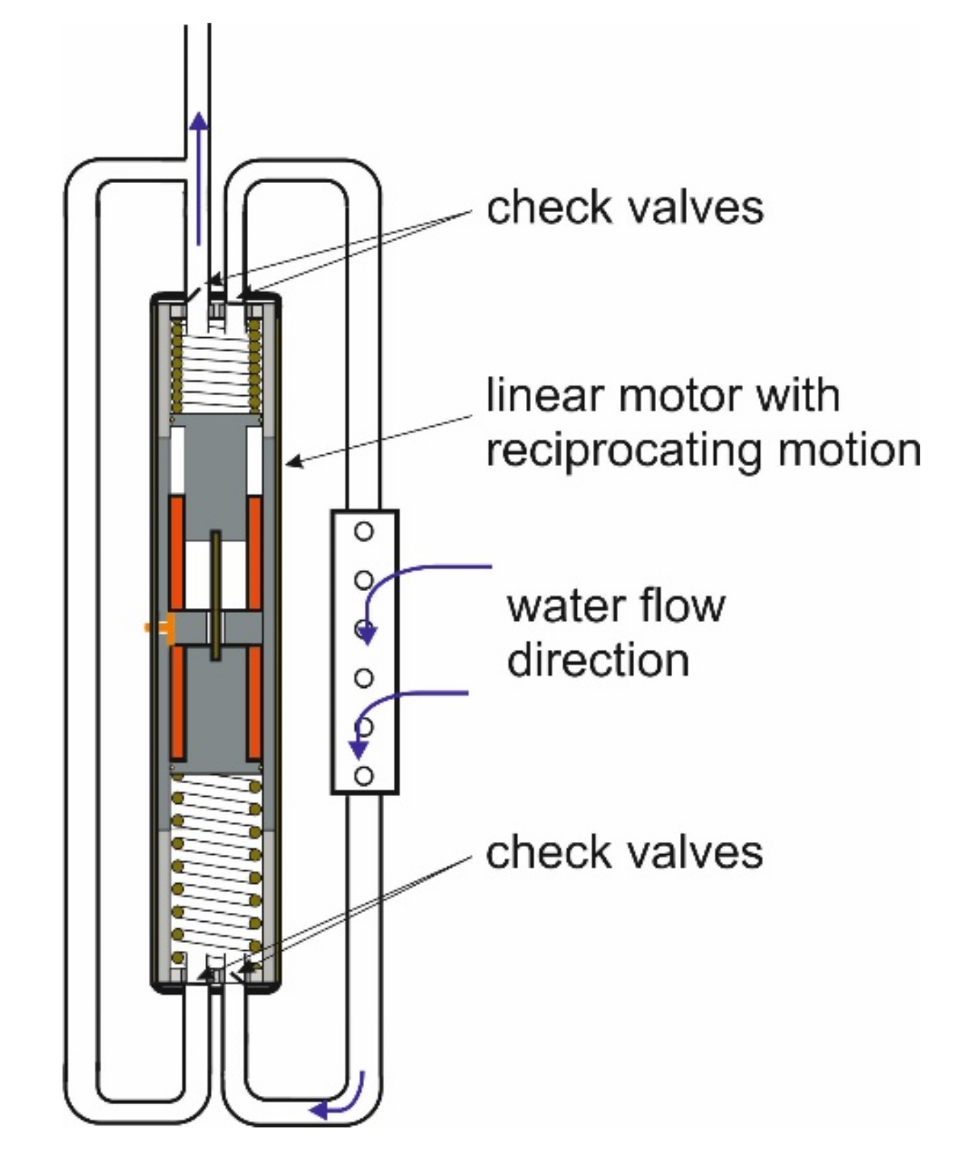
To obtain the relatively high water flow needed, a double piston motor was considered, which allows for the pumping of water in each half of the operation cycle. The pump used for this type of motor is shown schematically in
Figure 1. This pump has a double piston and four check valves.
In this paper, the description of the motor is presented first. Next, an analysis of the static forces and a calculation of the coil inductances is conducted using FEM. Then, motor operation is simulated using MATLAB/Simulink and the waveforms of voltage, currents, forces, speed, and piston displacement are shown. Finally, the simulation results are compared with those obtained from the measurements carried out on the motor prototype.
2. Motor Dimensions and Supply Circuit
Among SRLTMs, two design versions can be observed; one with a single primary coil and one with double coils. The former develops magnetic force in one direction while the return motion is caused by the compressed spring. Another example of an SRLTM with a single coil or coils connected in series, which generates a reciprocating motion, is presented in [
11,
12,
13]. These motors, however, do not generate the starting force. To generate the starting force required, some asymmetry must be introduced in the magnetic circuit or in the mechanical system. To introduce mechanical asymmetry, two springs of different compliance have to be applied. Introducing asymmetry to the motor structure reduces the motor’s performance. A motor with double coils does not have these negative features, since it develops strong magnetic force in both directions. Additionally, if the springs are added, the trajectory of the driving force matches the required shape.
Referring to these features, the new SRLTM with double coils was considered for further analysis and is shown schematically in
Figure 2. The stator consists of two coils placed in a tube made of soft magnetic material. The secondary part consists of two pistons connected stiffly to one another by a stainless-steel rod. The coils are supplied alternately from the DC source. When the lower coil is energized, then the relevant piston (the lower piston) is pulled up by the magnetic field of the coil. This causes the upper piston to move up as well. When at the upmost position, the lower coil is switched off while the upper coil is switched on. This causes the two pistons to move down. At the lowest position, the upper coil is switched off and the lower coil is simultaneously switched on. Thus, the reciprocating motion of the pistons is caused by alternately switching the stator coils on and off.
The waveforms of the voltages that supply the coils are shown in
Figure 3, where the subscripts 1 and 2 refer to the upper coil and lower coil, respectively.
The coils’ supply circuit is shown in
Figure 4, consisting of an H-bridge converter supplied from a DC source. To prevent the current from flowing through one coil while another is energized, a diode is connected in series with each of the coils. During the coils’ commutation, part of the magnetic energy of the switched-off coil is transmitted to the switched-on coil and part is sent back to the battery. This ensures an increase in motor efficiency.
The oscillation frequency of the pistons depends on the voltage frequency. The voltage frequency can be controlled if the motor operates within a supply circuit, as shown in
Figure 5. The motor can also operate in closed-loop mode, with the piston position feedback shown in
Figure 6. In this case, the voltage frequency, and thus the piston’s mechanical frequency, will depend on motor load. The performance of the motor is expected to be better in this mode of operation, but the motor must be equipped with pistons position sensors.
The dimensions of the motor shown in
Figure 2 result from the requirements set for the pump driven by this motor. These are presented in [
14]. The data informing the construction of the springs were obtained from this study as well.
3. Simulation Model for Motor Dynamics
3.1. Motor Dynamic Model
The mathematical model of the motor is based on its electric circuit model (
Figure 7) and its mechanical model (
Figure 8). These are described by the equilibrium equations shown below.
For the electric circuit:
If the power losses in the power converter are ignored:
For the mechanical system:
where
is the load force exerted on the pistons by the pump water,
where
In the equations above, the magnetic driving force Fm(z,i) and the inductance L(z,i) are functions of the piston position and the coil current.
3.2. Parameters of Motor Dynamic Model
The simulation of the motor operation was performed for the motor with the parameters shown in
Table 1.
Rubbers placed at the bottom of cylinder were represented by springs, each with the parameters z
ro = 1 mm (see
Figure 8) and Kr = 2 × 10
4 N/m.
The magnetic force F
m, exerted on the piston was determined using FEM [
15]. The relationships between the characteristics of the force vs. the upper piston position, determined for different currents, are shown in
Figure 9a. The force exerted on the lower piston changes with the piston position in reverse order.
The coil inductance changes not only with the piston position; due to the saturation of the magnetic circuit, it also depends on the coil current.
Figure 9b shows the relationship between the upper coil inductance vs. piston displacement determined for different coil currents. The inductance of the lower coil changes similarly, but in reverse, with respect to the variable
z.
Having determined the magnetic forces, the springs were chosen. The springs were chosen by obtaining the force vs. displacement characteristics of the springs, as the force along the operational distance had to be relatively constant, with the maximum value at the extreme positions of the pistons. This high value of the force is particularly important when the given coil is switched on and the piston starts to move in the opposite direction. Then, the piston must overcome not only the load force due to moving the water up but also the inertia of the accelerating pistons and the pumped water. According to these criteria, the spring chosen had the constant K
s = 20 kN/m.
Figure 10 shows the static forces acting on the pistons vs. the piston displacement characteristic calculated at the coil current I = 20 A. In this figure,
Fm1 and
Fm2 stand for the magnetic forces exerted on the upper piston (1) and lower piston (2), and
Fs (dotted line) stands for the total force of the two springs. The resultant force characteristic (
Fm1 +
Fs and
Fm2 +
Fs) is marked with the arrows. These arrows show the direction of the moving pistons and the force exerted on them at particular positions. The force of the rubber acting on the pistons at the bottom of the cylinders is not considered here.
4. Simulation Results
The voltage (V) that supplies the winding, shown in
Figure 11, alternates according to the pistons’ up and down motion due to the position sensors. In the same figure, the voltage across the upper coil is shown. In the second half of the cycle the voltage becomes negative because of the inverter switching and remains such until the current in this coil drops to zero. In the beginning of the switching, the peaks of the waveforms show a slight increase in voltage caused by the decaying current in the switched-off coil.
The coil current (I
1) shown in
Figure 12 increases with some delay due to the coil inductance. When the voltage is reversed, in the first instant the current suddenly drops down due the negative additional voltage induced in the coil by the moving piston, whose speed change (
Figure 15) is caused by the springs and the rubber placed at the bottom of the cylinder. Then, the current decays to zero because of the inductance of the coil. In the same figure, the supply current (I
s) changes according to the change of current in the two coils. Due to the coil inductance and the type of supply circuit applied, the current reverses when part of the magnetic energy of the switched-off coil is sent back to the battery and another part supplies the switched-on coil.
The waveform of the input power shown in
Figure 13 is similar to the waveform of the current (I
s) that supplies the motor because the supply voltage (V
s) does not change much, remaining nearly constant. The waveform of the resultant magnetic force (
Fm =
Fm1 +
Fm2) is shown in
Figure 14. Since the resultant magnetic force depends not only on position but also on the current, its value changes partly according to the currents. When the voltage across one coil is switched off, its current still flows. Thus, the magnetic force of the newly switched-on coil pulls the piston in the opposite direction, as the magnetic force of the switched-off coil is still active and very high. The reverse motion of the pistons at this instance is caused mainly by the springs. This phenomenon is visible in the waveforms of both forces. The pure magnetic force is not very high when it changes its direction, but it increases when spring force is added.
Figure 15 shows the waveforms and speed of the piston displacement. The piston speed reverses rapidly when the piston approaches the bottom of the cylinder, where the rubber is placed. The piston is driven both by magnetic force and the springs located between the bottom and topmost positions. The action of the rubber is also visible in the displacement
z waveform. The descending side of the peaks of the waveform is very steep due to the action of the rubber. The rubber’s role is not visible on the ascending side because the magnetic force is very high and is opposite to the force of the rubber at the bottom of the cylinder.
5. Experimental Verification of Simulation Results
In order to validate the simulation results, measurements were carried out on the pump prototype shown in
Figure 16.
The measurements were taken at a no-load test.
Figure 17 and
Figure 18 show the waveforms of the coil current and supply current obtained from the simulation and from measurements.
In general, there are no large differences in the amplitude and frequency (which are around 13 A and 13.8 Hz, respectively). More visible differences are noticeable in the shape of the current at its peaks. In the waveforms obtained from the measurements, the current at the top slightly decrease, while the simulated current reaches its maximum just before switching off the coil. This difference may result from using a supply with different parameters from the one used in the simulation.
The waveforms in
Figure 18 characterize the different values at every second peak. This is caused by the fact that the motor prototype had coils that differed in the number of turns. One coil had 616 turns and another had 550 turns, influencing coil resistance and coil inductance. The resistances were respectively 2 Ω and 1.78 Ω. The inductance of the coil with the lower number of turns was determined using FEM for different piston positions and different currents, similar to how this was done in
Section 3.2.
Figure 19 presents the waveforms of the voltage across the coils. They slightly differ from one another, particularly in the part when the supply voltage is commuted to a negative value. In this part, the voltage across the coil does not drop to zero due to the current, which flows until it decays to zero. The negative coil voltage taken from the experiment slowly decreases to zero, while the voltage obtained from the simulation approaches zero more rapidly. This difference may come from the supply model, which may differ from the parameters of the real supply source.
In order to validate the theoretical model of the motor, its parameters should be the same as in the real motor. This condition can be reached, to some extent, for the electric part of the model. It is much more difficult to reach this condition for the mechanical system, particularly if the motor is loaded by the water flowing within the motor pistons and further through the pipes. Furthermore, the O-rings applied in the pistons change its friction during operation in the water environment. Due to these difficulties, the comparison of the test and simulation results was conducted for a no-load case.
6. Conclusions
The SRLTM presented in this paper is a new, double coil linear motor model. The motor has two mechanically connected back-to-back pistons, which move with reciprocating motion when the coils supplied from a DC source are switched on and off. The pistons, despite being the secondary part of the motor, are also simultaneously part of the pump. Thus, the motor, together with the pipes and check valves, is a motor–pump aggregate. At the start, when the coils are not energized, the pistons, being compressed by two springs, take the central position (
z = 0, see
Figure 8). At this position, after the upper coil is switched on, the pistons move down. Due to the position sensors, the pistons move with a reciprocating motion.
The main goal of this paper was to present the electromechanical properties of the motor on the basis of the proposed mathematical model. The parameters of the model, particularly the parameters of its mechanical part, were only estimated. This is because some of the parameters, like the friction of the O-rings and the load of pumped water, changed during motor operation. Furthermore, the power losses in the motor pistons and stator core cylinder caused by the pulsation of the coil current were ignored. Their contribution to the total electric power losses was rather small, and were around 25 W at 5 Hz frequency and 20 A current, with the position of the piston inside the stator cylinder. This is less than 3% of the 838 W ohmic power losses in the coil.
To validate the simulation model, measurements were carried out on the motor–pump prototype. The presented simulation and test results show minor differences between them. Despite these differences, they are relatively small from the motor operation point of view. Thus, it can be said that the applied mathematical motor model allows for an analysis of the motor operation that is accurate enough for engineering purposes.
The proposed design of the SRLTM engine largely meets expectations. However, in further development works, the use of permanent magnets in the motor structure can be considered. In addition, further work on the engine control system is also planned. In particular, the development of a sensorless method for determining the position of the engine pistons, which could replace the optocoupler sensors used in the described structure, will be considered.
Author Contributions
Conceptualization, K.D., M.K., and E.A.M.; data curation, K.D., M.K., and E.A.M.; formal analysis, K.D., M.K., and E.A.M.; funding acquisition, K.D. and P.D.; investigation, K.D., M.K., and E.A.M.; methodology, K.D., M.K., and E.A.M.; project administration, K.D., M.K., and E.A.M.; resources, K.D., M.K., and E.A.M.; software, K.D., M.K., E.A.M., and P.D.; supervision, K.D., M.K., and E.A.M.; validation, K.D., M.K., and E.A.M.; visualization, K.D., M.K., and E.A.M.; writing—original draft, K.D., M.K., E.A.M., and P.D.; writing—review and editing, K.D., M.K., E.A.M., and P.D. All authors have read and agreed to the published version of the manuscript.
Funding
This research received no external funding.
Data Availability Statement
Not applicable.
Conflicts of Interest
The authors declare no conflict of interest.
References
- WHO. 1 in 3 People Globally Do Not Have Access to Safe Drinking Water—UNICEF, WHO. Available online: https://www.who.int/news/item/18-06-2019-1-in-3-people-globally-do-not-have-access-to-safe-drinking-water-unicef-who (accessed on 20 November 2019).
- COMET-ME: Solar Magnetic Piston Pump. Available online: https://www.youtube.com/watch?v=OkpClH6ylbU (accessed on 18 April 2018).
- Short, T.D.; Oldach, R. Solar Powered Water Pumps: The Past, the Present—And the Future? J. Sol. Energy Eng. 2003, 125, 76–82. [Google Scholar] [CrossRef]
- Sashidhar, S.; Fernandes, B.G. A low-cost semi-modular dual-stack PM BLDC motor for a PV based bore-well submersible pump. In Proceedings of the International Conference on Electrical Machines (ICEM), Berlin, Germany, 2–5 September 2014; pp. 24–30. [Google Scholar] [CrossRef]
- Karassik, I.; Messina, J.; Cooper, P.; Heald, C. Pump Handbook, 4th ed.; McGraw-Hill Education: New York, NY, USA, 2007. [Google Scholar]
- ABEL GmbH. Available online: http://pressurewashr.com/pressure-washer-pumps/ (accessed on 18 January 2017).
- Huang, Y.; Nie, S.; Ma, K.; Liu, F.; Li, L. Static stress and modal analysis of water hydraulic reciprocating piston pump driven by the linear motor. In Proceedings of the International Conference on Fluid Power and Mechatronics (FPM), Harbin, China, 5–7 August 2015; pp. 914–917. [Google Scholar] [CrossRef]
- Zhang, Z.M.; Gong, Y.J.; Hou, J.Y.; Wu, H.P. Simulation on Linear-Motor-Driven Water Hydraulic Reciprocating Plunger Pump. Adv. Mater. Res. 2014, 842, 530–535. [Google Scholar]
- Boldea, I.; Nasar, S.A. Linear electric actuators and generators. IEEE Trans. Energy Convers. 1999, 14, 712–717. [Google Scholar] [CrossRef]
- Bianchi, N.; Bolognani, S.; Corda, J. Tubular linear motors: A comparison of brushless PM and SR motors. In Proceedings of the International Conference on Power Electronics, Machines and Drives (Conf. Publ. No. 487), Sante Fe, NM, USA, 4–7 June 2002; pp. 626–631. [Google Scholar]
- Mendrela, E.A.; Pudlowski, Z.J. Transients and dynamics in a linear reluctance self-oscillating motor. IEEE Trans. Energy Convers. 1992, 7, 183–191. [Google Scholar] [CrossRef]
- Mendrela, E.A. Comparison of the performance of a linear reluctance oscillating motor operating under AC supply with one under DC supply. IEEE Trans. Energy Convers. 1999, 14, 328–332. [Google Scholar] [CrossRef]
- Tomczuk, B.; Sobol, M. A field-network model of a linear oscillating motor and its dynamics characteristics. IEEE Trans. Magn. 2005, 41, 2362–2367. [Google Scholar] [CrossRef]
- Gwozdziewicz, M.; Kubiczek, M.; Mendrela, E.A. Analysis of Static Forces in Switched Reluctance Linear Tubular Motor for Reciprocating Pump. In Proceedings of the IEEE 18th International Symposium on Electromagnetic Fields in Mechatronics, Electrical and Electronic Engineering (ISEF), Łódź, Poland, 14–16 September 2017; pp. 1–2. [Google Scholar]
- Meeker, D. Finite Element Method Magnetics. Available online: http://www.femm.info/wiki/HomePage (accessed on 20 May 2016).
Figure 1.
Diagram of a lift-and-force pump driven by a linear motor with reciprocating motion.
Figure 1.
Diagram of a lift-and-force pump driven by a linear motor with reciprocating motion.
Figure 2.
Scheme of the switched reluctance linear tubular motor, with its main dimensions.
Figure 2.
Scheme of the switched reluctance linear tubular motor, with its main dimensions.
Figure 3.
The waveforms of the voltages that supply the coils.
Figure 3.
The waveforms of the voltages that supply the coils.
Figure 4.
Scheme of the power inverter that supplies the motor coils.
Figure 4.
Scheme of the power inverter that supplies the motor coils.
Figure 5.
Block diagram of the motor drive operating in an open loop frequency control.
Figure 5.
Block diagram of the motor drive operating in an open loop frequency control.
Figure 6.
Block diagram of the motor drive operating with a position feedback control loop.
Figure 6.
Block diagram of the motor drive operating with a position feedback control loop.
Figure 7.
Circuit diagram of the motor supplied from the battery through the power inverter.
Figure 7.
Circuit diagram of the motor supplied from the battery through the power inverter.
Figure 8.
Scheme of the motor’s mechanical system.
Figure 8.
Scheme of the motor’s mechanical system.
Figure 9.
Family characteristics of (a) the magnetic force acting on the piston and (b) the inductance of the coil vs. motor piston displacement calculated for different currents.
Figure 9.
Family characteristics of (a) the magnetic force acting on the piston and (b) the inductance of the coil vs. motor piston displacement calculated for different currents.
Figure 10.
The magnetic forces Fm and spring force Fs acting on the upper (1) and lower (2) motor pistons at 20 A coil current.
Figure 10.
The magnetic forces Fm and spring force Fs acting on the upper (1) and lower (2) motor pistons at 20 A coil current.
Figure 11.
The waveforms of voltage that supply the motor winding (V) and the voltage across the upper coil (Vc).
Figure 11.
The waveforms of voltage that supply the motor winding (V) and the voltage across the upper coil (Vc).
Figure 12.
The waveforms of the current that flows through the upper coil (I1) and the supply current (Is).
Figure 12.
The waveforms of the current that flows through the upper coil (I1) and the supply current (Is).
Figure 13.
The waveform of input power (Pin).
Figure 13.
The waveform of input power (Pin).
Figure 14.
The waveforms of the resultant magnetic force (Fm) and the resultant force (magnetic + spring force (Fm + Fs)) acting on the upper piston.
Figure 14.
The waveforms of the resultant magnetic force (Fm) and the resultant force (magnetic + spring force (Fm + Fs)) acting on the upper piston.
Figure 15.
The waveforms of the piston displacement (z) and the piston speed (u).
Figure 15.
The waveforms of the piston displacement (z) and the piston speed (u).
Figure 16.
Motor–pump prototype.
Figure 16.
Motor–pump prototype.
Figure 17.
The waveforms of the coil current (I1) for no-load at 36 V supply: (a) simulation results; (b) test results.
Figure 17.
The waveforms of the coil current (I1) for no-load at 36 V supply: (a) simulation results; (b) test results.
Figure 18.
The waveforms of the supply DC current (Is) for no-load at 36 V supply: (a) simulation results; (b) test results.
Figure 18.
The waveforms of the supply DC current (Is) for no-load at 36 V supply: (a) simulation results; (b) test results.
Figure 19.
The waveforms of voltage across the coil (Vcoil) at the no-load condition: (a) simulation results; (b) test results.
Figure 19.
The waveforms of voltage across the coil (Vcoil) at the no-load condition: (a) simulation results; (b) test results.
Table 1.
The parameters of the motor.
Table 1.
The parameters of the motor.
| Parameter | Value |
|---|
| Eb | 36 V |
| Rb | 0.01 Ω |
| C | 1 mF |
| R1 = R2 | 2 Ω |
| Mp (mass of the pistons and the water) | 30 kg |
| Ks1 = Ks2 | 2 × 10⁴ N/m |
| z01 = −z02 | 16 mm |
| D | 4 N/m/s |
| Publisher’s Note: MDPI stays neutral with regard to jurisdictional claims in published maps and institutional affiliations. |
© 2021 by the authors. Licensee MDPI, Basel, Switzerland. This article is an open access article distributed under the terms and conditions of the Creative Commons Attribution (CC BY) license (http://creativecommons.org/licenses/by/4.0/).


