Abstract
Permanent magnet synchronous motors (PMSMs) have attracted great attention in the field of electric drive system. However, the disturbances caused by parameter mismatching, model uncertainty, external load and torque ripple seriously weaken the control accuracy. The traditional adaptive sliding mode control (ASMC) methodology can address slow-varying uncertainties/disturbances whose frequencies are located at the bandwidth of the filter used to design the adaptive law well; however, it has been barely discussed with respect to the periodic situation. In this paper, we extend the ASMC arrangement to periodic case to suppress the torque ripple by using a series-structure resonant controller. Firstly, a typical SMC is designed to force the tracking error of speed to converge to zero and obtain a certain capacity to disturbance. Then, the improved adaptive law is incorporated to estimate the lumped disturbance and torque ripple. The improved adaptive law is enhanced by embedding the resonant controller, which can obtain a better estimating result for torque ripple with repetitive feature. Finally, simulation and experimental results with PI, SMC and proposed methods are compared to verify the effectiveness of the developed controller.
1. Introduction
Permanent magnet synchronous motors (PMSMs) have been widely applied in the fields of robotics, electric propulsion ships and numerical control machines due to the superiorities such as high-power density, high-torque ratio and wide-speed regulation range, etc. [1,2,3,4]. Generally, PMSMs can be classified into two types (i.e., the interior and the surface-mounted PMSMs). Comparing with the surface-mounted PMSM, the interior one has the advantages of simpler manufacturing process and higher power density. However, its magnetic flux leakage coefficient and manufacturing cost are larger than those of surface mounted rotor structure. The surface-mounted PMSM can obtain excellent control performances such as precise tracking trajectory, fast transient response and satisfactory robustness to external disturbances, and is of great concern in precise manufacturing with high-performance requirements. The motors of the two structures have practical applications in different occasions, thus it is necessary to develop a disturbance compensation strategy independent of the model of the motor.
Despite the advantages of PMSMs (including the interior and the surface-mounted structures), some undesired features, such as uncertain disturbance, nonlinearity of controlled model, high-order complex dynamics and torque ripple, deteriorate the control performance of PMSMs [5,6,7,8,9,10]. These problems correspond to the controller design, which can be divided into the following two types named p1 and p2. The p1 is the challenge factor of robustness to lumped disturbances, and the p2 is the torque ripple in current and speed loops.
To solve p1, varied control methods have been designed for PMSM such as proportional integral (PI) controller [11], fuzzy control [12], robust control [13], active disturbance rejection control (ADRCs) [14,15] and model predictive control (MPCs) [16,17]. The PI controller is simple and reliable, which is the most typical and dominant control method in servo control system. However, this linear control method has difficulty suppressing the disturbances existing in the control loop owing to the fact that it does not have any compensation term. Fuzzy control is established by the fuzzy rules to improve the robustness with respect to disturbance, which can ensure strong anti-disturbance capacity to deal with external load and model uncertainty. However, it has the following drawbacks: its stability and robust stability are difficult to guarantee, and the fuzzy rules are heavily relied on the experience of the users. Robust control is based on the H-infinity synthesis to design the controller, which has successful application in the field of aerospace and large-scale system. However, this optimized method is too conservative to give full play to the performance of the controller [18]. In [19], the ADRC is design in current loop to improve the robustness to the varying of inductance and resistance. This control method provides a new solution to achieve satisfactory dynamic response and anti-disturbance ability. However, it needs complex control law design, which limits its application to industry. MPC is a modern control strategy, becoming a possible candidate for electrical drives, owing to its advantages of a fast dynamic response and ensuring satisfactory robustness to disturbance. Nevertheless, it has the following limitations: the calculation of the control command depends on the system model, and the weight coefficient used in the MPC is difficult to determine.
Sliding mode controller (SMC) is an advanced nonlinear control strategy formed by a switching surface, which can force the trajectory to reach the sliding mode state from anywhere. Once on the switching surface, the behavior of the system is reduced to a stable linear time-invariant system, which is immune to the disturbances including its internal or external sources [20]. Therefore, SMC is remarkably suitable to solve the issues of parameters mismatching and uncertain disturbances, i.e., p1. SMC can ensure strong robustness by setting a large switching gain. However, this will result in serious chattering phenomenon, which may excite the high-frequency dynamics. To further enhance the disturbance rejection performance, the observer-based control technique is introduced, which is available in [21,22,23,24,25,26]. The observer-based control strategy is composed by the SMC and a disturbance observer. The SMC can be designed according to the specific tracking performance and the stability property to obtain expected dynamic response, while the observer is designed to compensate the disturbance and uncertainty. This methodology can solve the conflict requirements of tracking performance and robustness to disturbance. Despite its advantage, the modeling uncertainty and the non-minimum phase property may cause the observer to not work well [18,27].
The adaptive SMC (ASMC) provides a practical solution to improve the robustness of SMC because the disturbance compensation term does not require the parameters of a control plant [28,29,30]. The adaptive law can estimate the internal and external disturbances while ensuring robustness property against parameter uncertainties. However, it is difficult to suppress the torque ripple caused by p2, due to the fact the torque ripple has the periodic characteristic.
There are several control methods used to address p2, such as repetitive control (RC) and iterative learning control (ILC). RC is simple and reliable, but its transient response is slow [31]; ILC can effectively reject the repetitive disturbance, but it will produce large overshoot before iterative error converging to zero [1,28]. Furthermore, some other control techniques used to reduce torque ripple can be found in [32], and these methods have shown certain effect to decrease torque ripple.
Resonant controller is a popular method to deal with a periodic signal, which is widely applied in the applications of wind generator, inverter and AC signal control [33]. The resonant controller is based on the internal mode principle, i.e., any type disturbances can be suppressed by embedding suitable internal model of the disturbances in the forward channel [34]. Inspired by this thinking and [28,29,30], this paper proposed a new robust SMC based on an adaptive law and a series connecting resonant controller. The proposed control approach benefits the traditional adaptive law and a resonant control term, which can observe both non-periodic and periodic disturbances. These observed disturbances including torque ripple will be regarded as a feedforward term to timely compensate the actual interference of the system. Finally, the simulations and experiments are carried out to validate the superiority of the proposed control strategy.
2. Analysis of the PMSM
2.1. Mathematical Model of the PMSM
The establishment of mathematical model of the PMSM is based on the coordinate transformation, which is given by [1]
where , , , , and are the voltages, currents and inductances along d-q axis, respectively. and are the derivatives of the d and q axis currents; is the resistance and represents the electrical angular frequency satisfying , in which p and denotes the pole pairs and mechanical angular frequency.
The mechanical dynamic equation can be expressed as follows [1,28,29]:
where and are the inertial and frictional coefficient, respectively; is the electromagnetic torque, and is the torque coefficient; is the flux linkage. If the surface-mounted type PMSM is used for the drive system, which indicates , this parameter can be further simplified as . is the external load torque.
When parameter matching is considered, the disturbance can be expressed as
where is the model error; and are the disturbances in d-q axis; is the disturbance in speed loop. These disturbances will result in poor dynamic response and steady-state performance in speed tracking, which should be suppressed in high performance drive system.
2.2. Torque Ripple Analysis for the PMSM
When the motor runs in the low-speed condition, the harmonic torque will produce large fluctuation in speed and current. The harmonic torque is mainly produced by dead time effect of inverter, current measurement error, and flux harmonics; among them, the amplitudes of the harmonic torque caused by dead time effect of invert can be expressed as [35]
where and represent the harmonics in d and q axis, respectively; , , , and are the amplitudes of harmonics, voltage caused dead effects, and initial phase angles, respectively. The electric angular frequency is associated with the speed of motor, i.e., . It can be seen that the amplitude of the 6th harmonic component is inversely proportional to the motor speed. When the motor runs in a high-speed condition, the impact of harmonics to the motor speed can be expressed as
It can be observed that the ratio is decreased with the increasing speed, which indicates the influence of torque ripples in high-speed operating is relatively small. The dead time effect of inverter produces 6 times harmonic components in current loop and results in the same order fluctuation to the speed [35];
The current measurement error is caused by the current sensor converted by voltage, which will result in 1 and 2 times of the fundamental electrical frequency torque ripples in the speed, and they can be expressed as
in which and are the torque ripples caused by current offset error and current scaling error, respectively; and represent the DC offsets of phase currents and ; and are the proportional coefficients of the two phases; denotes the amplitude of phase current.
The flux harmonic is another momentous source resulting torque ripples, which is composed of 5 and 7 times of fundamental frequency components in a-b-c axis corresponding to 6 times of fundamental frequency contents in d-q axis. The amplitude of the torque ripple caused by flux harmonics is given by
where is initial phase of the (6i)th flux harmonic.
These torque ripple will decrease the control performance of the PMSM, especially in the low-speed condition. Therefore, a suitable compensation strategy for torque ripple should be developed in the low-speed range.
3. Controller Design of PMSMs
To suppress the disturbance caused by parameter mismatching, external load and torque ripple, this paper proposes an improved adaptive sliding mode control law for PMSMs. First of all, the traditional adaptive law is discussed to highlight its advantages and shortcomings, which motivated us to propose the improved scheme. Subsequently, the proposed control strategy is applied to the speed loop to reduce the impact of these disturbances on control system.
3.1. Sliding Mode Controller Design
The control model of speed loop can be descripted by a first order liner sate space equation, which has the following form:
where is state variable, F and G are the coefficients composed of the nominal model; is the control input; is the lumped disturbance.
When the sliding mode control law is designed for the system in (8), the integral-type sliding mode surface and the derivative of the tracking error can be expressed as follows:
where represents the switching function in terms of the current or velocity error ; is the integral coefficient satisfied , which ensures the tracking error converge to zero.
The derivative of the switching function is called the reaching law, which has various forms summarized in [19]. In order to avoid the chattering caused by switch function and obtain certain capacity robustness to disturbances, the regular exponential reaching law is adopted in this paper, which is given as follows:
where and are the switching gain and exponential coefficient of the reaching law. According to the principle of SMC, the reaching law (10) can force the tracking error to converge to the equilibrium point form of any initial state. The convergence rate is proportional to the value of , and large can provide faster convergence rate; however, more severe chattering phenomenon will occur in the system. Therefore, should be selected between chattering and convergence rate, which limits the anti-disturbance ability.
By uniting (8)–(10), the feedback control law can be expressed as follows:
where is the reference input in system (8).
3.2. Traditional Adaptive Law Design
According to the analysis in Section 2.1, the lumped uncertainty and external disturbances unavoidably exist in servo control system; in order to suppress these disturbances, the adaptive law is proposed to estimate the lumped disturbance and compensate them online. The adaptive law is based on a low pass filter, which has the specific expression as follows [29]:
where and is the actual and estimated lumped disturbances; is a time constant, which is associated with the bandwidth of the filter.
Rewrite (12) into the differential equation, we can obtain
It is assumed that there is an error between the real disturbance and the estimated value; then, by uniting (13), we can further get
The overall control law can be expressed as
in which is the equivalent control value produced by the sliding mode controller to guarantee the tracking error converge to sliding mode surface, and is the compensation term provided by the adaptive law.
Using (9)–(11), the change rate of sliding surface function can be described by the following equation:
Substituting the terms and into (16), we can obtain
By uniting (14) and (17), the adaptive law can be expressed as follows:
According to (18) and (12), once the parameters of and are designed based on the principle in [29,36,37], the estimated quality only depends on the tuning. Smaller value of can ensure the estimated error faster to converge to zero whereas to provide larger estimated frequency-rang of the disturbance. That indicates the filter in (12) has larger bandwidth, which may cause the control system more sensitive to noise [38]. The influence of noise on the estimated frequency range limits the estimated ability of the torque ripple. To further improve the anti-disturbance capacity especially for the torque ripple, we proposed a modified filter to design the adaptive law, which will be detailed in the next section.
3.3. Analysis of the Resonant Controller
To suppress the torque ripple and obtain a higher integration level of the control structure, the resonant controller is embedded in the forward channel of the adaptive law, which has a series connection. According to [33], the resonant controller with series structure has the basic form as follows:
where and are the gain and damping coefficients; is the center frequency.
In order to analyze the frequency domain characteristic of , (19) is rewritten as follows:
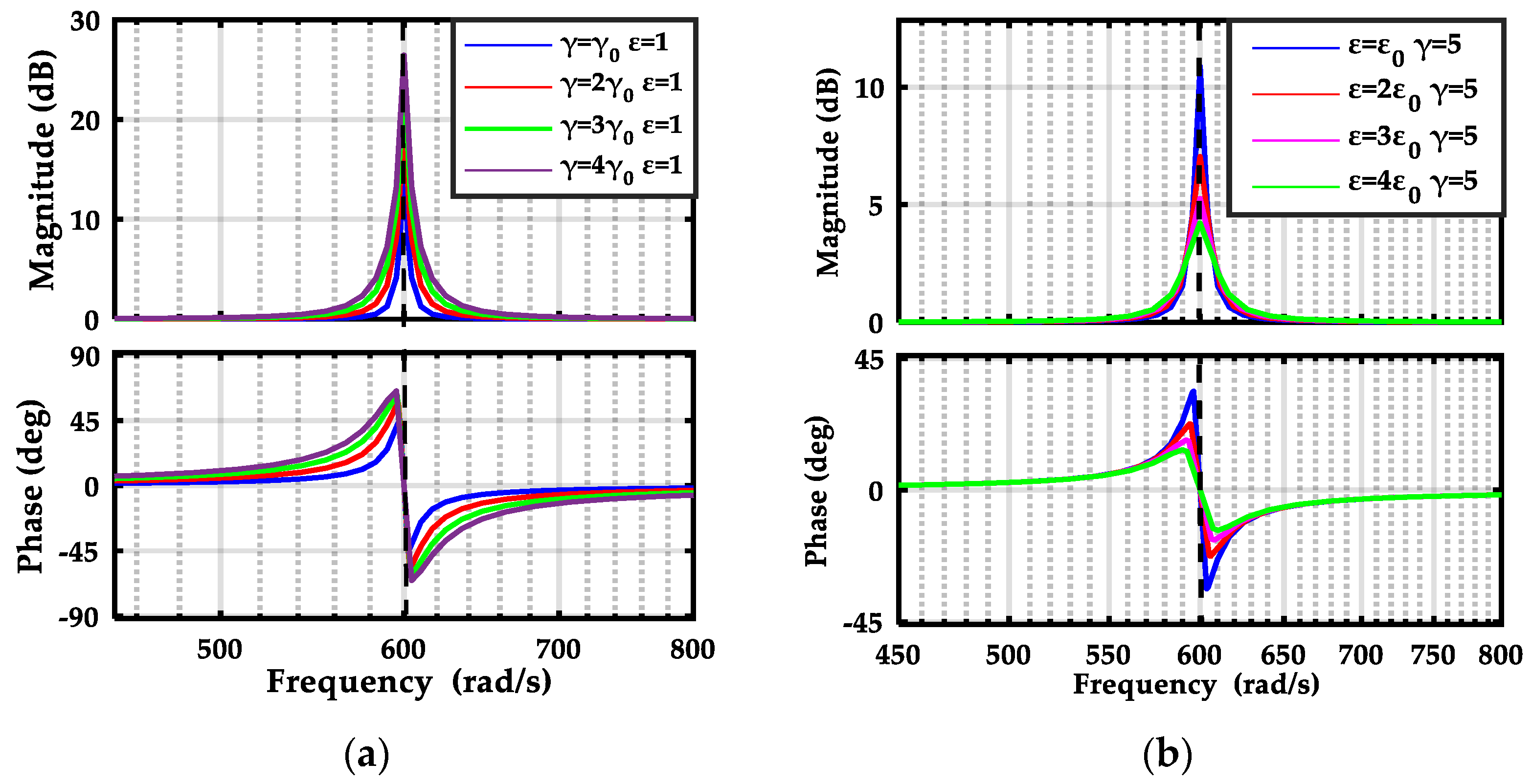
Note that , hence, it is not difficult to verify when . Meanwhile, it can be observed form (20) that is a parameter tuning the distance between the actual pole and the approximated pole , which determines the bandwidth of the resonant controller. Furthermore, if the frequency of the signal is outside of the bandwidth of the resonant controller, the gain is 1, which means that this kind of signal will not be affected by resonant controller. Figure 1 demonstrates the bode diagram when ε and change individually, and the resonant frequency selected for the example is set to δ = 600 rad/s. As can be observed from Figure 1a, the resonant gain increases with the enlargement of the gain coefficient γ, and the bandwidth remains unchanged. Therefore, γ can be considered an individual parameter to tune the peak gain of the resonant controller. Figure 1b exhibits the amplitude–frequency characteristics of the resonant controller with varying ε. It can be seen that the resonant gain is inversely proportional to the damping coefficient ε, and larger value of ε decreases the peak gain, but the bandwidth of the resonant controller is expanded. In practical engineering design, the reference value of this parameter is selected in the range of 5 to 15 rad/s.
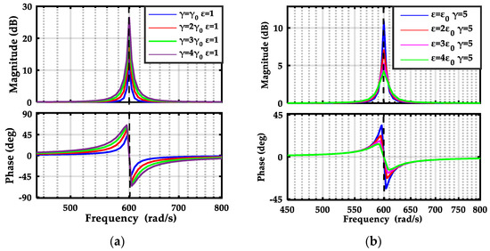
Figure 1.
Bode diagram of the resonant controller with varying γ and ε; (a) amplitude-frequency of the resonant controller with increasing γ and constant ε. (b) Amplitude-frequency of the resonant controller with increasing ε and constant γ.
3.4. Reformulation of the Adaptive Law
Using (12) and (19), the transfer function between estimated and actual disturbances can be rewritten as follows:
Then, the following equations are established
That imposes
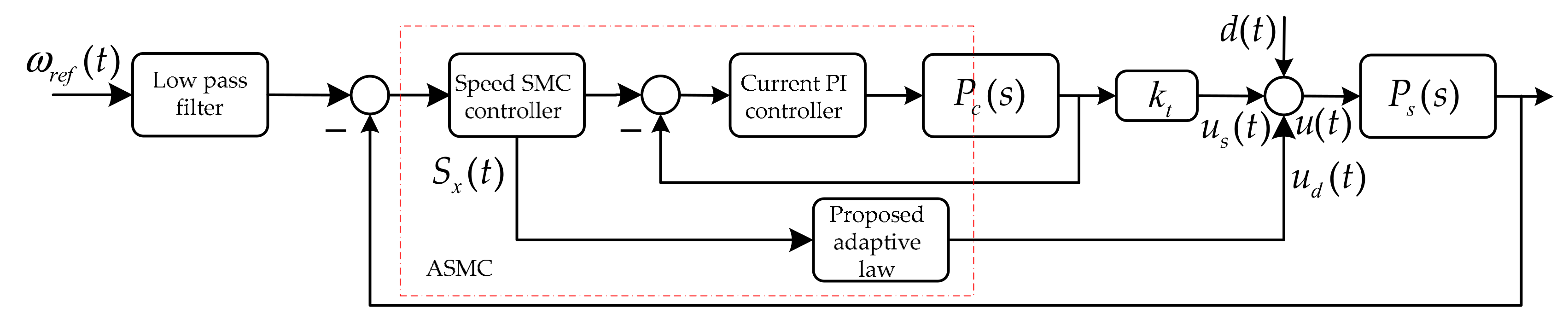
Moreover, the output of the disturbance to the inner loop system through the modified filter can be expressed as
The corresponding control diagram can be illustrated as Figure 2, and it can be observed that the modified filter can attenuate the disturbance entering the system despite this kind of disturbance cannot be modeled (the frequency of the disturbance is lower than 1/μ). Furthermore, it can be seen that the control law remains unaffected by the compensation term.
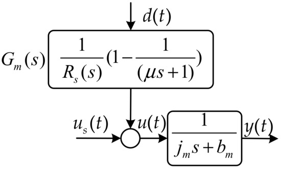
Figure 2.
Equivalent simplified block diagram inner closed loop.
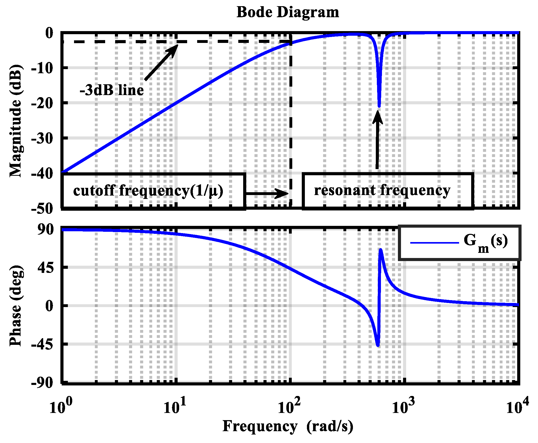
Figure 3 demonstrates the bode diagram of with the parameters of μ = 0.01, ε = 5, γ = 10 and δ = 600 rad/s; observing Figure 3, it is obviously seen that while the frequency of disturbance is lower than the cutoff frequency 1/μ, which can ensure satisfactory suppression capacity to slow time varying interference. When the torque ripple of 600 rad/s passes through the modified filter, its amplitude will be attenuated by 20 dB, which indicates the torque ripple will be suppressed.

Figure 3.
Bode diagram of .
Uniting (16) and (23), the improved adaptive law can be further expressed as
As can be observed from (25) that the traditional adaptive law (18) can be derived from (25) if . Hence, the traditional adaptive law is a special case of the propose control method, which indicates that the proposed adaptive law has wider application range.
In order to verify the stability of the proposed adaptive law, the Lyapunov analysis method is adopted, which will be used to establish the constraints of the closed loop system. The conditions for stability derived from the analysis method will result in important insight and provide guidelines for the parameters design of the disturbance estimator.
According to (23), the differential equation can be expressed as
where Di represents the ith differential operator.
Then, the state space state equation with the vector can be expressed as follows:
Thus, we have
where .
Using a positive and symmetric definite matrix to define the following Lyapunov function, which is given by
According to (28), the first derivative can be derived as follows:
where is a positive definite matrix, and represents the smallest eigenvalue of ; is a positive unknown number satisfied . According to [30], the system from the initial state will converge to equilibrium point by ensuring
Then, the estimated value will converge to actual value when .
4. Simulation and Experimental Verification
In order to verify the effectiveness of the proposed controller, the simulations and experiments are carried out in MATLAB (version R2016B) and a PMSM platform (Table 1 lists the parameters of the PMSM) in terms of robustness to disturbance and torque ripple suppression performances. The following controllers are utilized to compare with the proposed controller.

Table 1.
Parameters of the PMSM.
- (1)
- PI controller: the optimal PI controller is designed in this paper [33], and the parameters of the PI controller are set as and ; where l is a parameter determining the bandwidth the PI controller, and it is chosen as 11.5.
- (2)
- SMC: the parameters of the SMC are designed as , , and . For the sake of an impartial comparison, a low pass filter is added the reference input to obtain the same dynamic response with 98% ωref with the PI controller. The time constant is selected as 0.08 s.
The parameters of theses controllers are concluded in Table 2.
Table 2.
Parameters of the three control methods.
4.1. Simulation Results
4.1.1. Robustness to Motor Parameters Variation
To evaluate the transition performance of the controllers used in this paper, the indexes of overshoot and settling time are introduced, and defined as follows:
where is a step signal, and is the user-defined tolerance; is set 0.02 in this article.
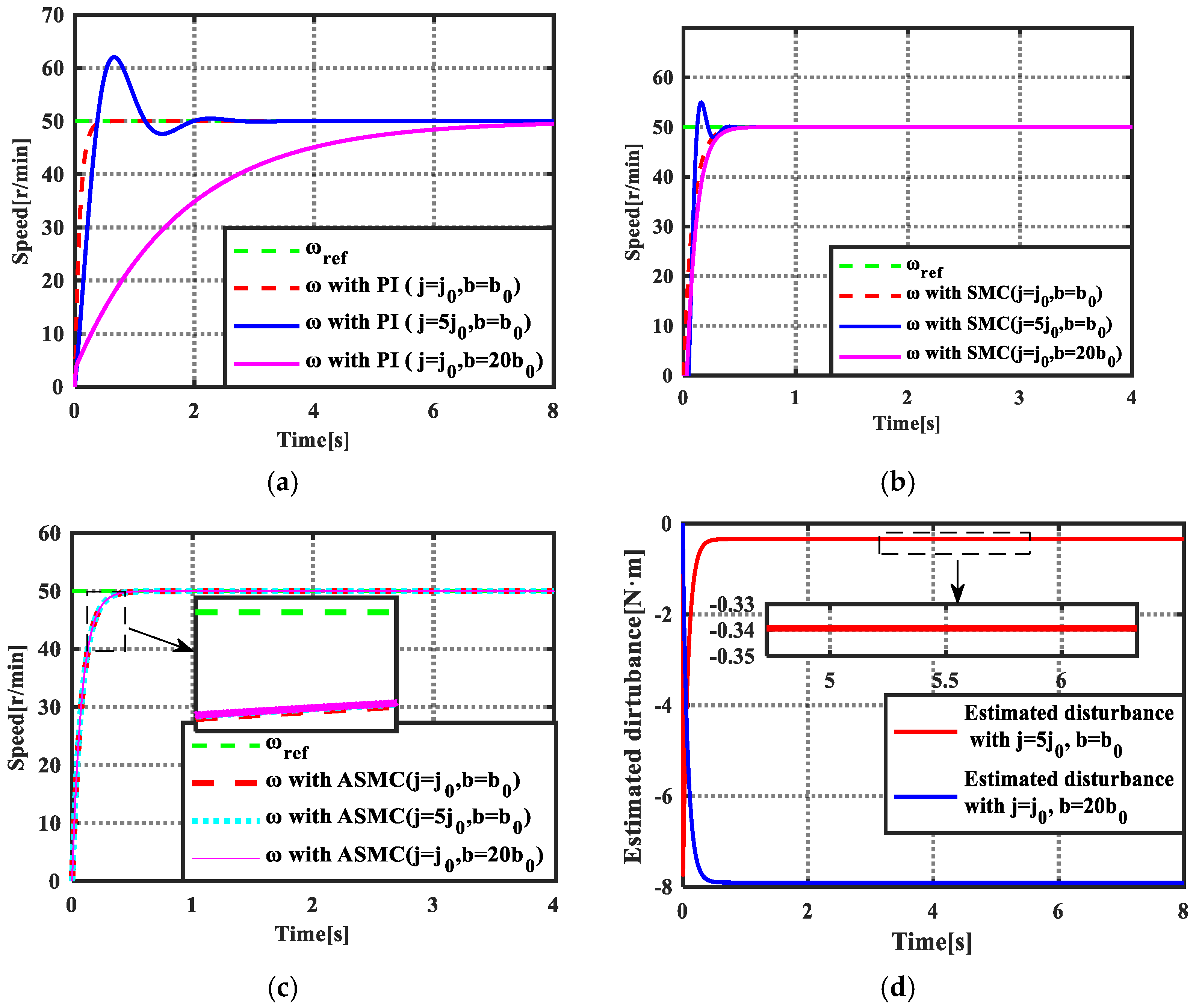
The overall simulation control block based on the proposed control methods is demonstrated in Figure 4 and Figure 5a shows the speed tracking performance using PI controller when mechanical parameters of the motor is changed. It can be seen that a large overshoot with the value of 24.08% occurred in the transition process when the inertial changed from j0 to 5j0; meanwhile, the settling time is extended from 0.322 s to 1.78 s. The viscous friction coefficient is another parameter affecting the dynamic response. It can be seen that the speed can track the given value without overshoot when b = 20b0, but the settling time has increased to 6.82 s. Figure 5b shows the dynamic response when SMC is used in speed loop. It can be observed that the overshoot and setting time are decreased to 12% and 0.35 s, respectively when inertial mismatch. Furthermore, the impact of viscous friction coefficient mismatch to tracking performance with SMC is further decreased, and the settling time only extends to 0.38 s. By comparing with PI and SMC, the proposed ASMC shows better robust performance to parameters mismatch, and the tracking trajectory has little change in the two testing cases. Moreover, the adaptive law can exactly estimate the equivalent disturbance to the control system; in the simulation, the estimated disturbances are 0.34 N·m and 7.89 N·m in the cases of j = 5j0 and b = 20b0.
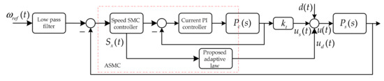
Figure 4.
Simulation control diagram of the proposed control strategy.

Figure 5.
Simulation results of dynamic response when parameters mismatch. (a) PI controller; (b) SMC method; (c) ASMC method; (d) the estimated disturbances when parameters mismatch.
4.1.2. Robustness to External Load
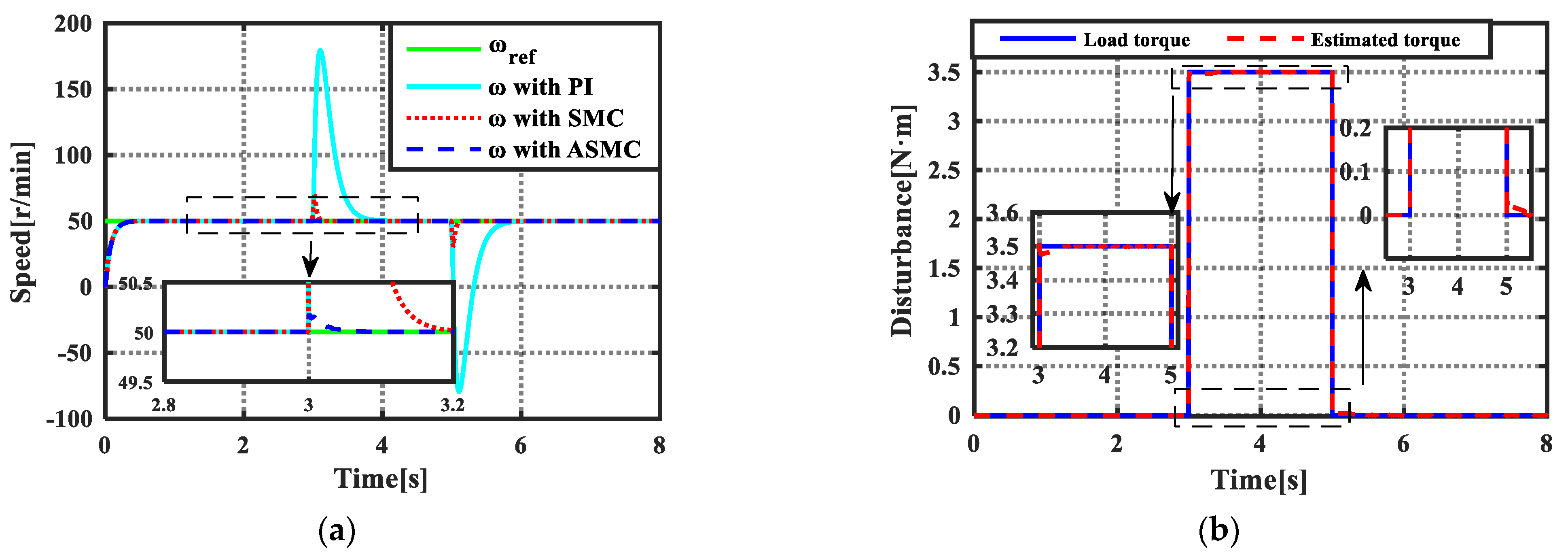
Figure 6 shows the speed tracking performance of three control methods when an external load of 3.5 N·m acts on the motor from 3 s to 5 s. The speed regulation is deteriorated by the external disturbance, and it can be obviously observed that the speed has a maximum mutation of 130 r/min. Meanwhile, the time required to return to steady state is 1.4 s, which is pretty large. The red trace shows the speed tracking performance with SMC, it can be seen that the maximum mutation is decreased to 19.6 r/min and the time returning to steady state is decreased to 0.356 s. The simulation results proves that the SMC has better disturbance suppression capacity. When the proposed adaptive law is adopted, the estimator can accurately observe the external disturbance and eliminate the disturbance as feedforward compensation, and the maximum mutation value of the speed is further decreased to 0.186 r/min, which is relatively small. In addition, the speed needs only 0.06 s to retrack the given value. The analysis mentioned above shows that the proposed ASMC exhibits the best disturbance rejection ability among three control methods.
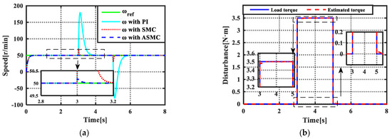
Figure 6.
Simulation results of disturbance rejection with external load. (a) The speed tracking performance with three control methods; (b) the estimated load torque and the load torque.
4.1.3. Torque Ripple Suppression Evaluation
According to [28], the speed fluctuation is mainly caused by 2nd and 6th harmonic torques; it is thus to add the following harmonic torque ripples to simulate the real torque ripple in the PMSM drive system:
The fast Fourier transformation (FFT) is utilized to analysis the speed and output torque with three control methods, and the total harmonic distortion (THD) value is introduced as an index to quantitatively investigate the torque ripple content in speed and output torque. The THD is defined by the following equation:
where and represents the amplitudes of ith harmonics and DC component calculated by FFT; is the amplitude percentage of the harmonics relative to DC component.
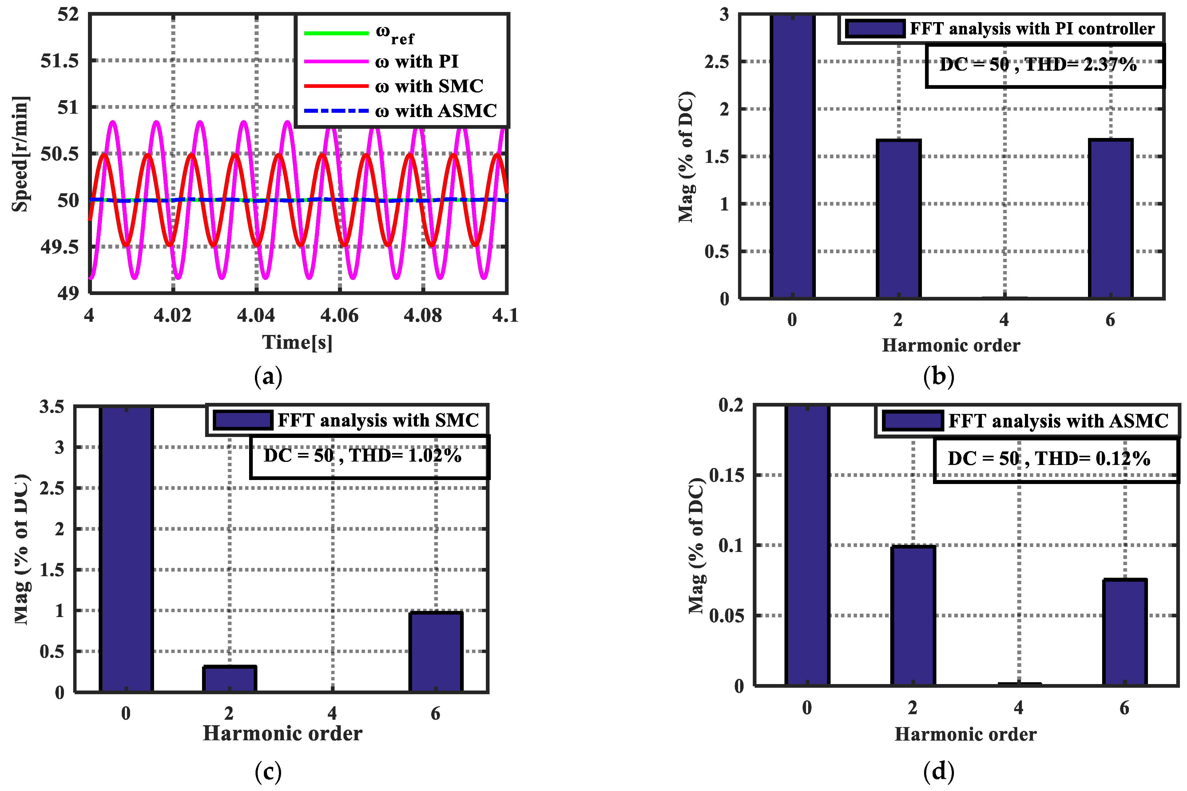
Figure 7a demonstrated the steady state performance of the speed with three control methods. It can be seen that a large fluctuation occurs in the speed when PI controller is used, and the amplitudes of 2nd and 6th harmonic components are 0.835 r/min and 0.84 r/min, respectively; the THD values reaches a value of 2.37%. The steady state performance of speed is improved when SMC is utilized, and the amplitudes of 2nd and 6th harmonic contents are decreased to 0.155 r/min and 0.485 r/min; compared with PI controller, the SMC has certain effect on restricting torque ripple. However, the THD value still has a large value of 1.02%. As can be seen from the blue trace using ASMC, the speed fluctuation is decreased to a smaller level by comparing PI controller and SMC, and the amplitudes of 2nd and 6th harmonic torques are reduced to 0.05 r/min and 0.04 r/min; The THD drops to a small value of 0.12%. It is apparent that the proposed ASMC can more significantly minimize the torque ripple.
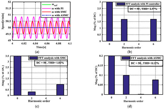
Figure 7.
Steady state performance of the speeds and their FFT analysis. (a) Speed curves using three control methods; (b) FFT analysis of the speed using PI controller; (c) FFT analysis of the speed using SMC; (d) FFT analysis of the speed using ASMC.
Figure 8 demonstrates the output torque curve using the three control strategies and their FFT analysis; the DC component of output torque is 0.4 N·m, and the amplitudes of the 2nd and 6th harmonics are 0.1672 N·m and 0.50 N·m, respectively, when PI controller is used (shown in Figure 8b). It is noted that the amplitudes of the added harmonics correspond to 2nd and 6th orders are 0.5/3 N·m and 0.50 N·m; the THD reaches a value of 132.31%. The simulation results prove that the conventional PI controller has little capacity to attenuate the torque ripple. Figure 8c shows the FFT analysis of the output torque with SMC, it can be observed that the amplitudes of theses harmonics are decreased, and the 2nd and 6th harmonics are 0.0314 N·m and 0.2887 N·m; the THD decreased to 73.28%. Though the SMC can minimize the torque ripple in some degree, the harmonic contents are still large. Figure 8d exhibits the FFT analysis of the output torque after compensation, and it can be seen that the amplitudes of 2nd and 6th harmonic torques are further reduced to 0.0098 N·m and 0.0226 N·m. The THD is dropped to 6.20%. The comparative results shows that the proposed control method has more significant effect to suppress torque ripple.
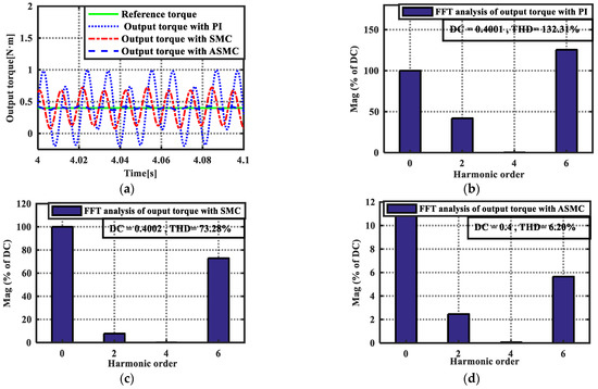
Figure 8.
Output torque curves with three control methods and their FFT analysis. (a) Output torque curves using three control methods; (b) FFT analysis of the output torque by using PI controller; (c) FFT analysis of the output torque by using SMC; (d) FFT analysis of the output torque by using ASMC.
To further verify the effectiveness of the proposed adaptive law, the torque ripple estimated results using (17) and the proposed method are compared in Figure 9. As can be seen from Figure 9a, the error between actual value and estimated value using conventional law is 0.27 N·m, which will produce large speed ripples in the steady state. This result proves that the conventional adaptive law has limited ability to suppress the torque ripple. When the proposed adaptive law is used, the estimated error is decreased to 0.08 N·m. It is obviously the proposed control strategy can obtain more remarkable result in suppression torque ripple.
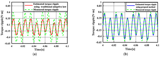
Figure 9.
Estimated results using (17) and the proposed method. (a) The torque ripple estimating result with (17). (b) The torque ripple estimating result with the proposed method.
4.2. Experimental Results
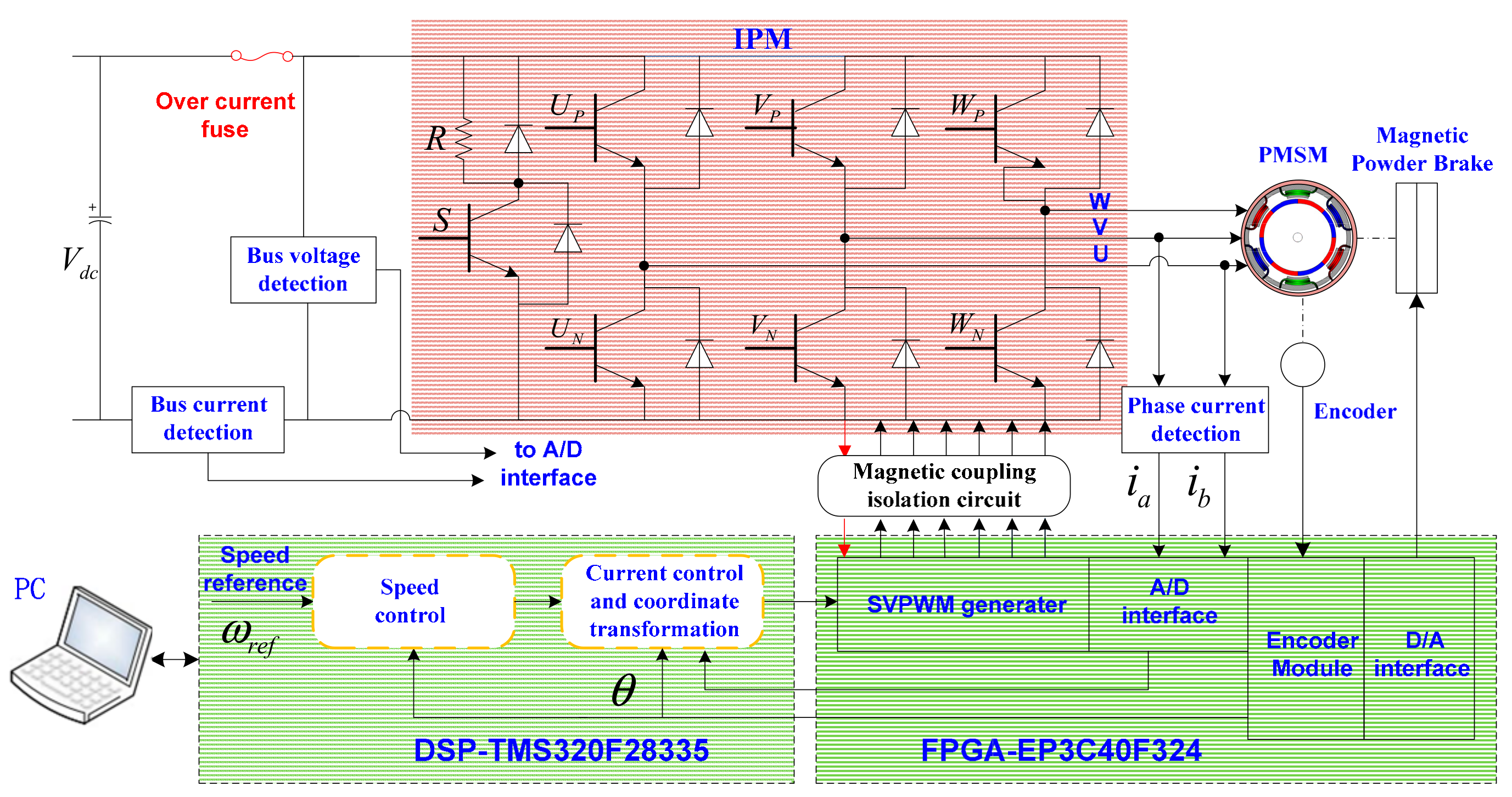
Figure 10 depicts the experimental platform of the PMSM based on the digital control structure of a TMS320F28335 DSP and EP3C40F324 field programmable array (FPGA); the corresponding control diagram is illustrated in Figure 11. The bus voltage of the inverter is 48 V, and the sampling frequency of the speed is 1 kHz. The space vector pulse width modulation and the speed control strategies are carried out in the DSP based on C program. An absolute encoder (the theoretical resolution is (360/218)°) is adopted to detect the position of the rotor.
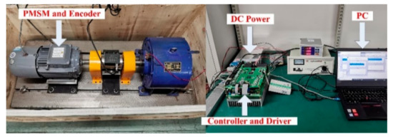
Figure 10.
PMSM servo system setups.
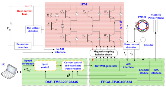
Figure 11.
Structural diagram of the PMSM servo system.
4.2.1. Robustness to Motor Parameters Variation
Figure 12 shows the experimental results of dynamic response with three control methods. It shoud be noted that the parameters of the motor can not be changed in the practical operation; it is thus we change the motor parameters involved in the controller with and (due to the limit page, we change the moment of inertia parameter and damping coefficient at the same time). It can be observed that a large overshoot and oscillation occur in the step response with PI controller, which extends the settling time of the control system. When SMC is employed, the overshoot and settling time is reduced, the transient process is enhanced. The red trace in Figure 12 depicts the dynamic response with ASMC, and it can be seen that the oscillation and overshoot are further eliminated. The setting time is also shortened. Figure 12b demonstrates the compensation term provide by the proposed adaptive law, which can reduce the lumped disturbance and accelerate the convergence rate of the speed. The experimental results shows that the proposed control method can ensure better transient process while achieve more satisfactory anti-disturbance performance.

Figure 12.
Experimental results of dynamic response and estimated disturbance during transient process. (a) Step response with three control strategies; (b) the estimated disturbances during transient process using proposed adaptive law.
4.2.2. Robustness to External Load
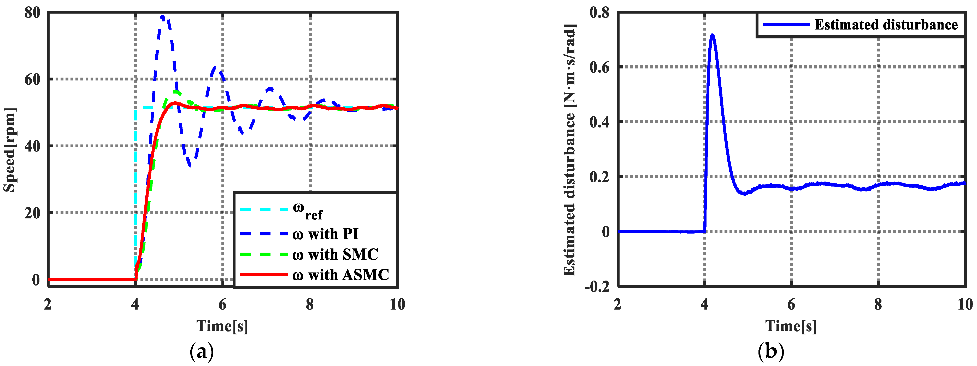
Figure 13a exhibits the steady-state performance of the three controllers when external load operates on the motor from 4–8 s. It can be obseved that the speed with PI controller has a variation of 7.5 rpm. Meanwhile, the speed needs a long time interval of 1.4 s to return the command value. The SMC has better anti-disturbance with respect to external load, and the speed varition and the time to retrace the command value are reuced to 4.9 rpm and 1.3 s, respectively. It is obviousely the SMC can guarantee better capacity to external load. When the proposed ASMC is configured, the speed variation is decreased to 3.10 rpm; furthermore, the time resuming to steady-state is reduced to 0.937 s. Therefore, it is apparent that the proposed control method can obtain better robustness to external load. Figure 13b shows the curves of estimated load and the actual load-disturbance. It can be revealed that the proposed adaptive law can observe the disturbance and compensate them on line.
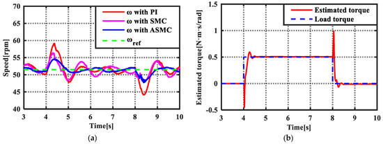
Figure 13.
Experimental results of disturbance rejection with external load. (a) The speed tracking performance with three control methods; (b) the estimated load torque and the load torque.
4.2.3. Torque Ripple Suppression Evaluation
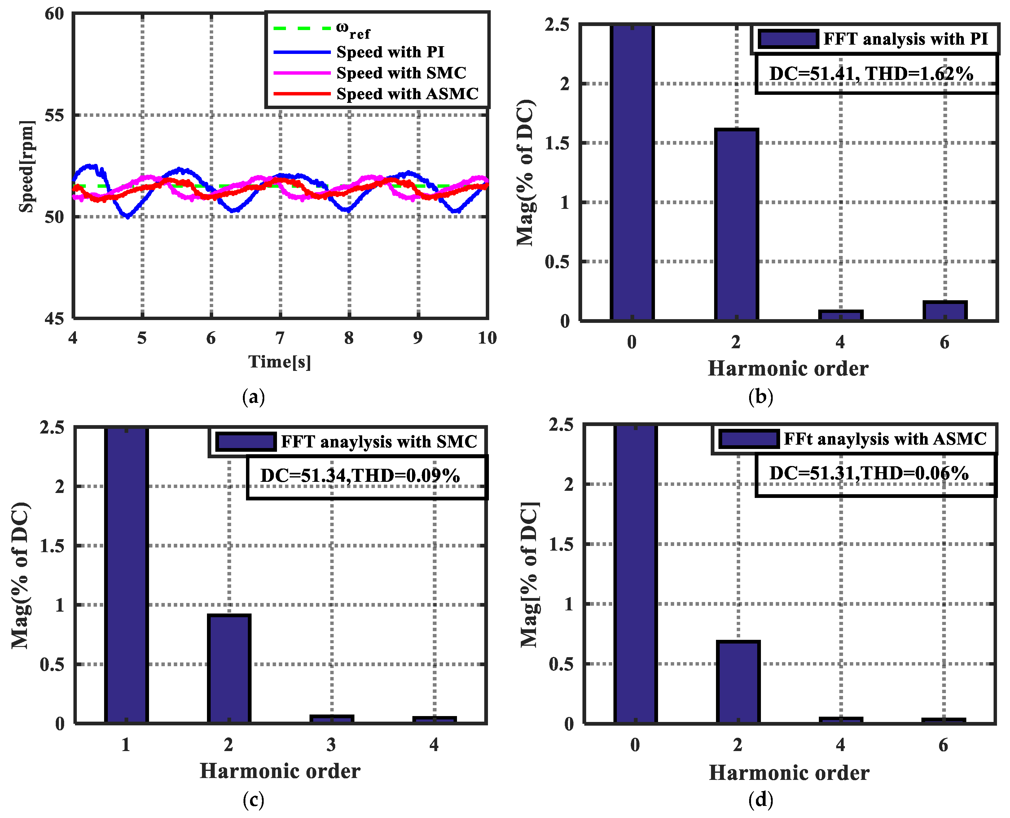
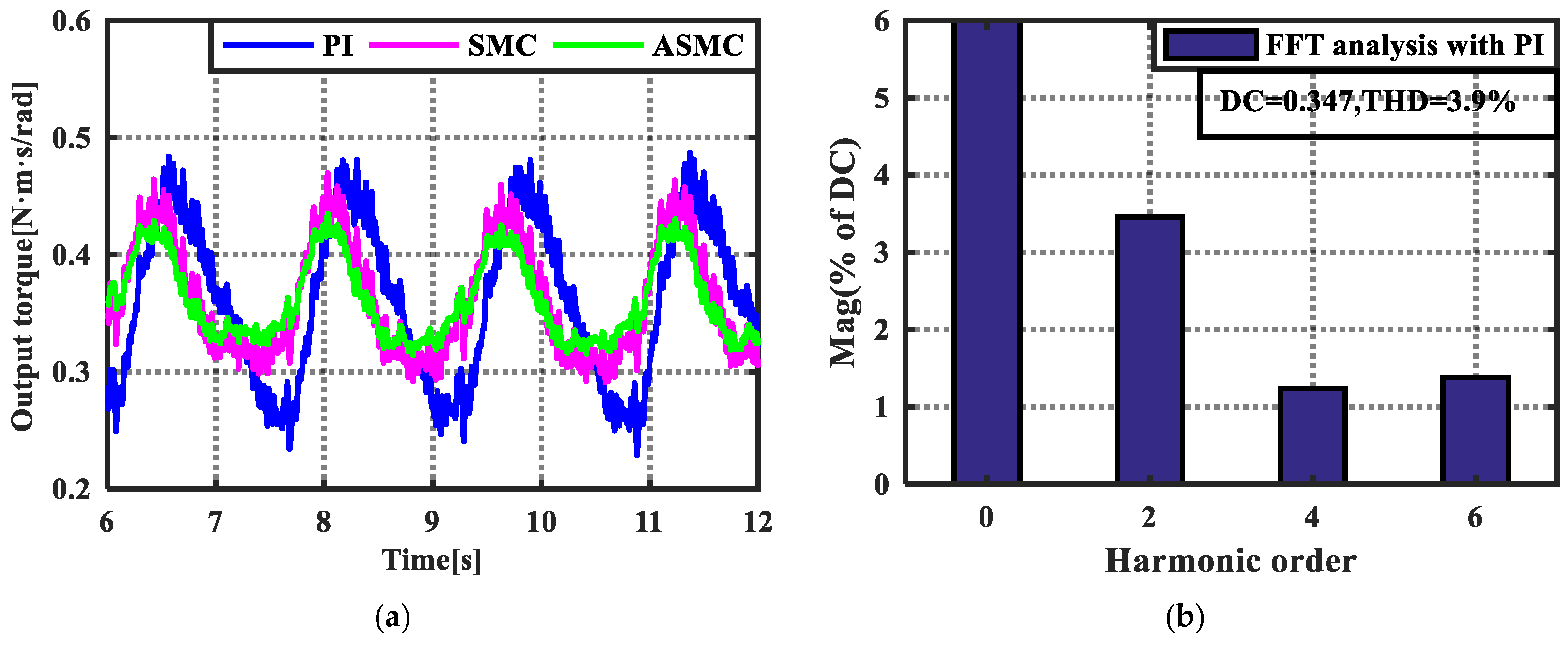
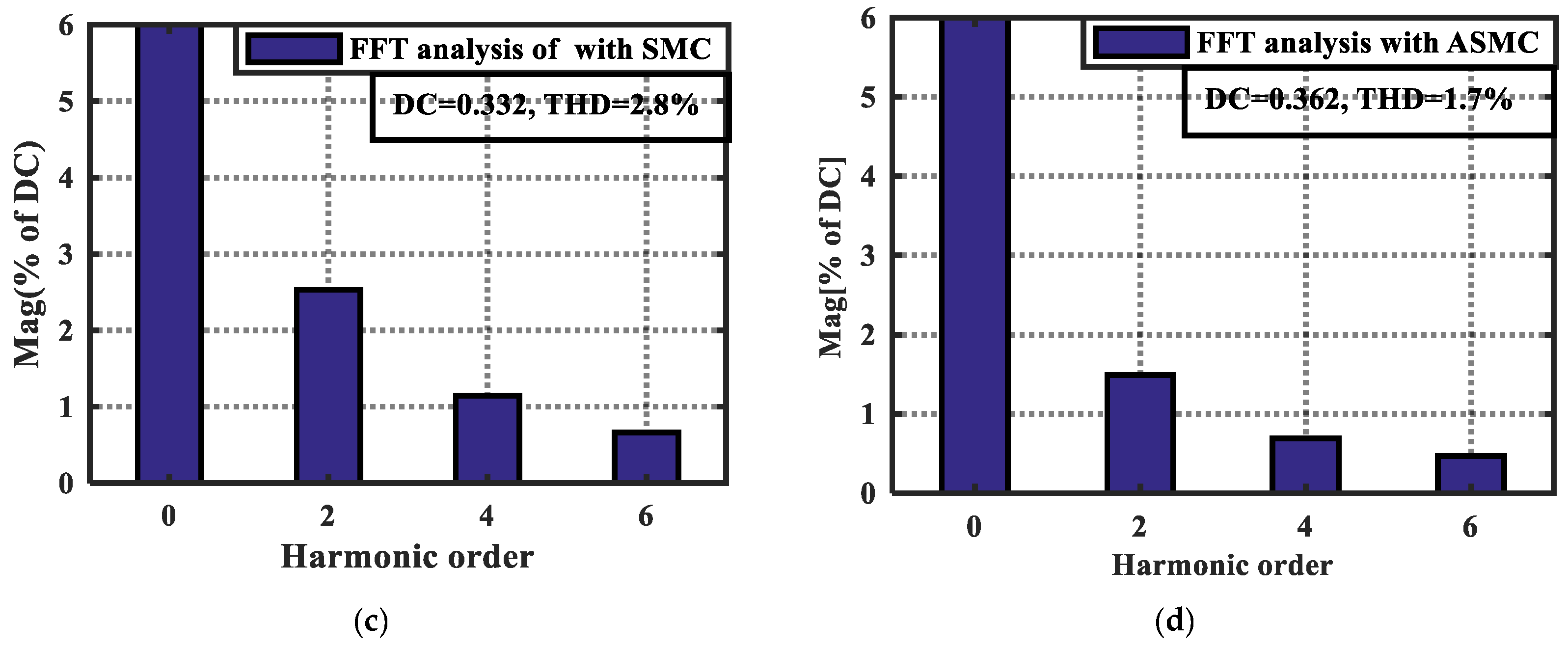
Figure 14 shows the experimental results of the speed using three controllers, it can be seen that the speed with PI controller has an average fluctuation of ±0.56 rpm, which deceases the steady-state accuracy. According to the FFT analysis, the DC component of the speed is 51.41 rpm and the THD caused by 2nd, 4th and 6th harmonic contents reaches a value of 1.62%. The SMC can improve the steady-state performance, the speed fluctuation is reduced to ±0.48 rpm, and the THD is decreased to 0.09%. When the ASMC is employed, the steady-state accuracy is further enhanced, and the speed ripple is dropped to ±0.35 r/pm. Meanwhile, the THD is reduced to 0.06%. Figure 15 demonstrates the output torque curves of the three control strategies, it can be revealed that the PI controller has limited capacity to suppress the torque ripple, and the THD of the output torque is 3.9%, which seriously decreased speed tracking performance. The SMC can suppress the torque ripple in some degree; however, the THD still reaches 2.8%. When the proposed control method is used, the torque curve is further improved, and the THD is decreased to 1.7%.

Figure 14.
Steady state performance of the speeds and their FFT analysis. (a) Speed curves using three control methods; (b) FFT analysis of the speed using PI controller; (c) FFT analysis of the speed using SMC; (d) FFT analysis of the speed using ASMC.
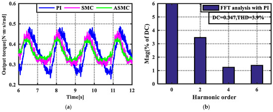
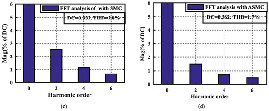
Figure 15.
Output torque curves with three control methods and their FFT analysis. (a) Output torque curves using three control methods; (b) FFT analysis of the output torque with PI controller; (c) FFT analysis of the output torque with SMC; (d) FFT analysis of the output torque with ASMC.
Figure 16 shows the torque ripple estimated results using (18) and the proposed method. It can be observed the amplitude of compensation term with the proposed method is larger than that with (17); it is not difficult to draw a conclusion that the enhanced adaptive law can better deal with torque harmonics.
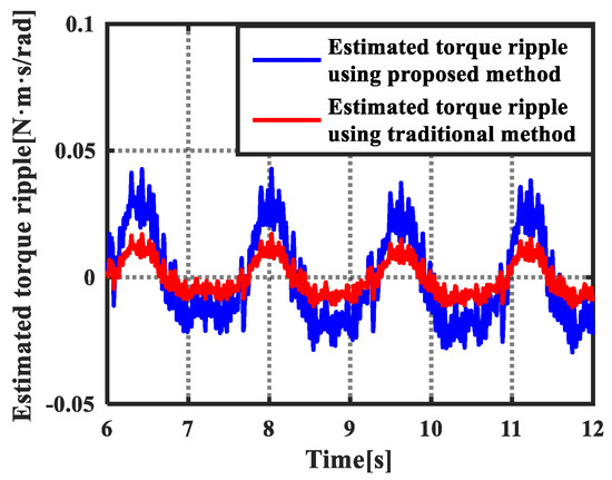
Figure 16.
Estimated results of Torque ripple using (18) and the proposed method.
The analysis above shows that the lumped disturbance including load torque, model uncertainty, and torque ripple can be effectively eliminated by the proposed adaptive law. The adaptive law enhanced by introducing a series resonant controller can more remarkably suppress the periodic torque ripple. Meanwhile, the SMC is established to regulate the speed and achieve certain capacity to the disturbance by means of the switching function. The ASMC combining with enhanced adaptive law and SMC techniques exhibits better control performances in terms of dynamic response, anti-disturbance and torque ripple suppression than the PI, SMC schemes.
5. Conclusions
This paper proposed a robust SMC approach for the PMSM by using an improved adaptive law. The modified adaptive law takes advantages of the traditional one and the resonant term, which can suppress the disturbances from various sources. Owing to embedding the resonant controller, the modified adaptive law remains unity gain and zero phase at DC and resonant frequency, enabling the PMSM improved capacity of periodic uncertainties and disturbances suppression. The adaptive law can improve the anti-disturbance ability of SMC, and minimize the switching gain, which can obtain better robustness and smaller chattering in the speed tracking. Simulation and experimental results show that the proposed control method can obtain better control performance than PI, SMC and the traditional ASMC strategies. By using the proposed control method, the THD values of speed has dropped to 0.12% and 0.06% in the simulation and experimental environments. The proposed robust ASMC is simple and does not dependent on the parameters of the PMSM. Thus, the proposed approach can be extended to other PMSMs to regulate the speed with high-requirements. In the future, we aim to develop the ASMC method for current loop considering electrical dynamics to further enhance the control performance of PMSM.
Author Contributions
M.H., Y.D. and H.L. designed the proposed control strategy; M.H., Y.D. and M.S. conducted the experiments, modeling and simulations; Y.D. and J.L. helped with writing the paper. All authors have read and agreed to the published version of the manuscript.
Funding
This work was supported in part by the National Natural Science Foundation of China (No. 11973041 and 12122304) and the Youth Innovation Promotion Association, CAS (2019218).
Institutional Review Board Statement
Not applicable.
Informed Consent Statement
Not applicable.
Data Availability Statement
The data are contained within the article.
Conflicts of Interest
The authors declare no conflict of interest.
References
- Mohammed, S.A.Q.; Nguyen, A.T.; Choi, H.H.; Jung, J.-W. Improved Iterative Learning Control Strategy for Surface-Mounted Permanent Magnet Synchronous Motor Drives. IEEE Trans. Ind. Electron. 2020, 67, 10134–10144. [Google Scholar] [CrossRef]
- Mohd Zaihidee, F.; Mekhilef, S.; Mubin, M. Robust Speed Control of PMSM Using Sliding Mode Control (SMC)—A Review. Energies 2019, 12, 1669. [Google Scholar] [CrossRef] [Green Version]
- Sun, X.; Wu, M.; Lei, G.; Guo, Y.; Zhu, J. An Improved Model Predictive Current Control for PMSM Drives Based on Current Track Circle. IEEE Trans. Ind. Electron. 2021, 68, 3782–3793. [Google Scholar] [CrossRef]
- Hou, Q.; Ding, S.; Yu, X. Composite Super-twisting Sliding Mode Control Design for PMSM Speed Regulation Problem Based on a Novel Disturbance Observer. IEEE Trans. Energy Convers 2020. to be published. [Google Scholar] [CrossRef]
- Wang, Y.; Feng, Y.; Zhang, X.; Liang, J. A New Reaching Law for Anti-disturbance Sliding-Mode Control of PMSM Speed Regulation System. IEEE Trans. Power Electron. 2020, 35, 4117–4126. [Google Scholar] [CrossRef]
- Hu, W.; Ruan, C.; Nian, H.; Sun, D. Zero-Sequence Current Suppression Strategy with Common-Mode Voltage Control for Open-End Winding PMSM Drives with Common DC Bus. IEEE Trans. Ind. Electron. 2021, 68, 4691–4702. [Google Scholar] [CrossRef]
- Gong, C.; Hu, Y.; Chen, G.; Wen, H.; Wang, Z.; Ni, K. A DC-Bus Capacitor Discharge Strategy for PMSM Drive System with Large Inertia and Small System Safe Current in EVs. IEEE Trans. Ind. Inform. 2019, 15, 4709–4718. [Google Scholar] [CrossRef]
- Zhou, X.; Sun, J.; Li, H.; Song, X. High performance three-phase PMSM open-phase fault-tolerant method based on reference frame transformation. IEEE Trans. Ind. Electron. 2019, 66, 7571–7580. [Google Scholar] [CrossRef]
- Hang, J.; Zhang, J.; Xia, M.; Ding, S.; Hua, W. Interturn Fault Diagnosis for Model-Predictive-Controlled-PMSM Based on Cost Function and Wavelet Transform. IEEE Trans. Power Electron. 2020, 35, 6405–6418. [Google Scholar] [CrossRef]
- Zhang, Y.; Jin, J.; Huang, L. Model-Free Predictive Current Control of PMSM Drives Based on Extended State Observer Using Ultralocal Model. IEEE Trans. Ind. Electron. 2021, 68, 993–1003. [Google Scholar] [CrossRef]
- Liu, K.; Hou, C.; Hua, W. A Novel Inertia Identification Method and Its Application in PI Controllers of PMSM Drives. IEEE Access 2019, 7, 13445–13454. [Google Scholar] [CrossRef]
- Murshid, S.; Singh, B. Implementation of PMSM Drive for a Solar Water Pumping System. IEEE Trans. Ind. Appl. 2019, 55, 4956–4964. [Google Scholar] [CrossRef]
- Saravanakumar, R.; Ali, M.S.; Huang, H.; Cao, J.; Joo, Y.H. Robust H∞ state-feedback control for nonlinear uncertain systems with mixed time-varying delays. Int. J. Control Autom. Syst. 2018, 16, 225–233. [Google Scholar] [CrossRef]
- Zhou, K.; Ai, M.; Sun, Y.; Wu, X.; Li, R. PMSM Vector Control Strategy Based on Active Disturbance Rejection Controller. Energies 2019, 12, 3827. [Google Scholar] [CrossRef] [Green Version]
- Liu, C.; Luo, G.; Chen, Z.; Tu, W. Measurement delay compensated LADRC based current controller design for PMSM drives with a simple parameter tuning method. ISA Trans. 2020, 101, 482–492. [Google Scholar] [CrossRef] [PubMed]
- Shao, M.; Deng, Y.; Li, H.; Liu, J.; Fei, Q. Sliding Mode Observer-Based Parameter Identification and Disturbance Compensation for Optimizing the Mode Predictive Control of PMSM. Energies 2019, 12, 1857. [Google Scholar] [CrossRef] [Green Version]
- Fei, Q.; Deng, Y.; Li, H.; Liu, J.; Shao, M. Speed ripple minimization of permanent magnet synchronous motor based on model predictive and iterative learning controls. IEEE Access. 2019, 7, 31791–31800. [Google Scholar] [CrossRef]
- Zheng, M.; Lyu, X.; Liang, X.; Zhang, F. A Generalized Design Method for Learning-Based Disturbance Observer. IEEE/ASME Trans. Mechatron. 2021, 26, 45–54. [Google Scholar] [CrossRef]
- Wang, Z.; Zhao, J.; Wang, L.; Li, M.; Hu, Y. Combined vector resonant and active disturbance rejection control for PMSLM current harmonic suppression. IEEE Trans. Ind. Inform. 2020, 16, 5691–5702. [Google Scholar] [CrossRef]
- Brahmi, B.; Laraki, M.H.; Brahmi, A.; Saad, M.; Rahman, M.H. Improvement of sliding mode controller by using a new adaptive reaching law: Theory and experiment. ISA Trans. 2020, 97, 261–268. [Google Scholar] [CrossRef]
- Zhang, X.; Sun, L.; Zhao, K.; Sun, L. Nonlinear Speed Control for PMSM System Using Sliding-Mode Control and Disturbance Compensation Techniques. IEEE Trans. Power Electron. 2013, 28, 1358–1365. [Google Scholar] [CrossRef]
- Kim, H.; Son, J.; Lee, J. A High-Speed Sliding-Mode Observer for the Sensorless Speed Control of a PMSM. IEEE Trans. Ind. Electron. 2011, 58, 4069–4077. [Google Scholar]
- Feng, Y.; Yu, X.; Han, F. High-Order Terminal Sliding-Mode Observer for Parameter Estimation of a Permanent-Magnet Synchronous Motor. IEEE Trans. Ind. Electron. 2013, 60, 4272–4280. [Google Scholar] [CrossRef]
- Lu, W.; Tang, B.; Ji, K.; Lu, K.; Wang, D.; Yu, Z. A New Load Adaptive Identification Method Based on an Improved Sliding Mode Observer for PMSM Position Servo System. IEEE Trans. Power Electron. 2021, 36, 3211–3223. [Google Scholar] [CrossRef]
- An, Q.; Zhang, J.; An, Q.; Shamekov, A. Quasi-Proportional-Resonant Controller Based Adaptive Position Observer for Sensorless Control of PMSM Drives Under Low Carrier Ratio. IEEE Trans. Ind. Electron. 2020, 67, 2564–2573. [Google Scholar] [CrossRef]
- Ke, D.; Wang, F.; He, L.; Li, Z. Predictive Current Control for PMSM Systems Using Extended Sliding Mode Observer with Hurwitz-Based Power Reaching Law. IEEE Trans. Power Electron. 2021, 36, 7223–7232. [Google Scholar] [CrossRef]
- Son, Y.I.; Kim, I.H.; Choi, D.S.; Shim, H. Robust cascade control of electric motor drives using dual reduced-order PI observer. IEEE Trans. Ind. Electron. 2015, 62, 3672–3682. [Google Scholar] [CrossRef]
- Liu, J.; Li, H.; Deng, Y. Torque ripple minimization of PMSM based on robust ILC via adaptive sliding mode control. IEEE Trans. Power Electron. 2018, 33, 3655–3671. [Google Scholar] [CrossRef]
- Deng, Y.; Wang, J.; Li, H.; Liu, J.; Tian, D. Adaptive sliding mode current control with sliding mode disturbance observer for PMSM drives. ISA Trans. 2019, 88, 113–126. [Google Scholar] [CrossRef]
- Ebrahimkhani, S. Robust fractional order sliding mode control of doubly-fed induction generator (DFIG)-based wind turbines. ISA Trans. 2016, 63, 343–354. [Google Scholar] [CrossRef]
- Li, C.-X.; Gu, G.-Y.; Yang, M.-J.; Zhu, L.-M. High-speed tracking of a nanopositioning stage using modified repetitive control. IEEE Trans. Autom. Sci. Eng. 2017, 14, 1467–1477. [Google Scholar] [CrossRef]
- Song, Z.; Zhang, Z.; Komurcugil, H.; Lee, C.H.T. Controller-Based Periodic Disturbance Mitigation Techniques for Three-Phase Two-Level Voltage-Source Converters. IEEE Trans. Ind. Inform. 2021, 17, 6553–6568. [Google Scholar] [CrossRef]
- Huang, M.; Deng, Y.; Li, H.; Wang, J. Torque ripple suppression of PMSM using fractionalorder vector resonant and robust internal model control. IEEE Trans. Transp. Electrif. 2021. to be published. [Google Scholar] [CrossRef]
- Joo, Y.; Park, G.; Back, J.; Shim, H. Embedding internal model in disturbance observer with robust stability. IEEE Trans. Autom. Control 2016, 61, 3128–3133. [Google Scholar] [CrossRef]
- Liang, W.; Wang, J.; Luk, P.C.; Fang, W.; Fei, W. Analytical Modeling of Current Harmonic Components in PMSM Drive with Voltage-Source Inverter by SVPWM Technique. IEEE Trans. Energy Convers. 2014, 29, 673–680. [Google Scholar] [CrossRef] [Green Version]
- Mystkowski, A. Lyapunov Sliding-Mode Observers with Application for Active Magnetic Bearing Operated with Zero-bias Flux. J. Dyn. Syst. Meas. Control 2018, 141. [Google Scholar] [CrossRef]
- Zhang, Y.F.; Li, S.J.; Lu, G. Design for Sensorless Permanent Magnet Synchronous Motor Servo System Based on Sliding Mode Observer. In Proceedings of the IEEE International Conference on Intelligent Computation and Industrial Application, Shenzhen, China, June 2011; pp. 133–136. [Google Scholar]
- Umeno, T.; Hori, Y. Robust speed control of dc servomotors using modern two degrees-of-freedom controller design. IEEE Trans. Ind. Electron. 1991, 38, 363–368. [Google Scholar] [CrossRef]


Publisher’s Note: MDPI stays neutral with regard to jurisdictional claims in published maps and institutional affiliations. |
© 2021 by the authors. Licensee MDPI, Basel, Switzerland. This article is an open access article distributed under the terms and conditions of the Creative Commons Attribution (CC BY) license (https://creativecommons.org/licenses/by/4.0/).