Abstract
The speed response of the interior permanent magnet synchronous motor (IPMSM) drive at low speeds was analyzed. To eliminate the effect of external disturbance or parameter uncertainty, a nonlinear speed control loop was designed based on the sliding-mode exponential reaching law, which reduces chatter, which is the major drawback of the constant reaching law sliding-mode control technique. The proposed nonlinear speed control eliminates speed ripples at low speed under load disturbance. The problem of speed convergence at low speed is caused by electromagnetic torque ripples, which cause shaft speed oscillations that affect drive performance. The main objective of the proposed method is to change the traditional IPMSM control design by compensating with an appropriate signal along the reference current and across the output of the speed control loop. To optimize the speed tracking performance during disturbances or parametric variations, a nonlinear speed control scheme is designed that can vigorously adapt to the change in the controlled system. The comparative analysis shows that the method provides excellent transient performance (e.g., fast convergence response, less overshoot, and fast settling time) and standstill performance (e.g., reduced steady-state error) compared with conventional control methods at low speed under varying load conditions. The method is easy to implement and does not require additional computational cost. To demonstrate the effectiveness and feasibility of the design approach, a numerical analysis was conducted, and the control scheme was verified using MATLAB/Simulink considering various operating conditions.
1. Introduction
Interior permanent magnet synchronous motors (IPMSMs) are extensively used in several high-performance industrial applications (e.g., electric vehicle drives, robotics, traction drives, and home appliances) owing to their significant properties, such as fast dynamics, high precision, high torque and power density, dynamic performance, low maintenance cost, and high reliability. Precise rotor shaft speed and position information are needed to achieve high-performance vector control [1,2]. However, at low speed, because of the presence of external disturbances, such as parasitic torque ripples or parameter uncertainties, caused by imperfect machine design, the uncertain data measured from the sensor caused by noise and the effect of mechanical load or power electronic switches [3,4] cause the speed trajectory tracking performance to deteriorate and degrade the robustness. Therefore, it is necessary to reduce the periodic torque ripples and overcome the effects of parametric variation to ensure high-precision trajectory tracking performance of IPMSM drives.
Various control techniques for solving the aforementioned problems have been presented in the literature. Several control strategies based on conventional controllers, such as proportional–integral (PI) control [5,6] have attracted attention owing to their simplicity and ease of implementation on hardware; however, they are highly dependent on actual drive parameters and require exact parameter values to tune the PI gain to achieve efficient closed-loop performance. To eliminate the parameter dependency on the control design, nonlinear controllers have been developed [7,8,9,10,11,12,13,14]. In previous research [7,8,9], deadbeat control showed excellent speed tracking performance, but it depends highly on the IPMSM parameters to achieve efficient tracking performance by setting the closed-loop poles to zero. Fuzzy logic controllers [10,11] can effectively deal with drive nonlinearities and model unknown parameter uncertainties. However, this control scheme depends highly on gains and requires extensive knowledge to choose appropriate fuzzy interference rules to achieve excellent speed tracking. Model predictive control (MPC) [12,13,14] is easy to implement and straightforward, but highly depends on the exact model of the IPMSM to predict the future control output variables that ensure adequate closed-loop control effects.
Variable structure control (VSC) was first studied in the 1950s for high-order differential systems, but, because of excessive chattering in the VSC system and the lack of an appropriate design approach, it has become less popular among researchers [15]. After the 1970s, the importance of VSC was further explored because of its robustness, quick response, and easy implementation. Moreover, system parametric variation and external disturbance are not issues, and VSC shows excellent dynamic performance [16]. In previous studies [16,17,18,19], the sliding mode control (SMC) scheme was applied to various applications owing to its invariance to external disturbances and unknown model parameter variations, which ensures excellent speed tracking performance regardless of parameter uncertainties or disturbances. The robustness of SMC highly depends on large control gains, whereas a large gain value causes a chattering issue, which excites higher-frequency dynamics. To suppress this issue, a reaching law is designed based on an exponential term that adopts the change of system states and the sliding surface. Therefore, in this study, an exponential reaching law SMC was applied to eliminate the issue of high chattering and slow reaching time.
Parasitic electromagnetic torque ripples are caused by several factors, such as the cogging torque, periodic flux harmonic, sensor measurement uncertainties, and current offset [20], which cause periodic speed ripples and degrade the control performance of the drive, especially under low-speed operating conditions. The fluctuation in speed can even cause instability in the system [21]. Torque pulsation can be divided into two high- and low-frequency components. By increasing the bandwidth of the closed-loop control, the high-frequency torque pulsating component can be effectively controlled, whereas, for the low-frequency component, which occurs within the closed-loop control bandwidth, further attention is required [22].
Several control schemes have been proposed in recent years to reduce the periodic torque ripples. The schemes are classified into two groups. The first focuses on the machine design and improvement of the machine structure (e.g., improving the winding distribution, skewing the slots or magnet, or guaranteeing the fractional number of slots per pole) [23,24]. Machine design optimization is the most effective way to minimize periodic torque ripples; however, once the machine structure is designed, the performance cannot be modified. In addition, optimizing the structure design results in a higher cost and more complex realization. The other group tends to minimize periodic torque ripples by employing advanced controllers that improve the performance of the motor drive by correcting and compensating for periodic torque ripples [25,26,27]. In an earlier study [25], the current compensation signal was added across the q-axis reference current to suppress the disturbance factor that helps to reduce the periodic speed oscillation caused by periodic torque ripples. MPC is designed in such a way that it reduces speed ripples because of the embedding disturbance frequency caused by the current sensor offset error [12]. In other work [26,27], a hybrid control scheme employing a finite control set MPC and lookup table was implemented to compensate for torque ripples caused by cogging.
To improve the dynamic and standstill response of an IPMSM drive at low speed, an effective compensation scheme along with a sliding-mode speed controller was implemented in this study. The proposed control schemes guarantee speed ripple reduction under low-speed working conditions. The speed control loop was designed based on exponential reaching law sliding-mode control (ERL-SMC), which is independent of the motor model, and the compensation signal was injected across the reference current and the output of the speed control loop. This was done to utilize low-frequency current and torque disturbance, which helps to modify actual reference variables in such a way that the controller rejects unwanted disturbing signals. The proposed control scheme was compared with conventional field-oriented control. The results show that the proposed scheme can effectively compensate for torque ripples that significantly increase the drive performance in terms of rotor shaft speed ripple minimization and transient/steady-state performance. Moreover, the proposed control scheme is simple and does not require a high computational cost.
The remainder of this article is organized as follows. A mathematical model and the maximum torque per ampere (MTPA) scheme for an IPMSM are introduced in Section 2. In Section 3, the source of periodic torque ripples is explained. The design process of sliding-mode speed control combined with a compensation scheme is described in Section 4. The results obtained to verify the effectiveness of the proposed control scheme are presented and discussed in Section 5. Finally, the contribution of this study is summarized in Section 6.
2. IPMSM Modeling and Control
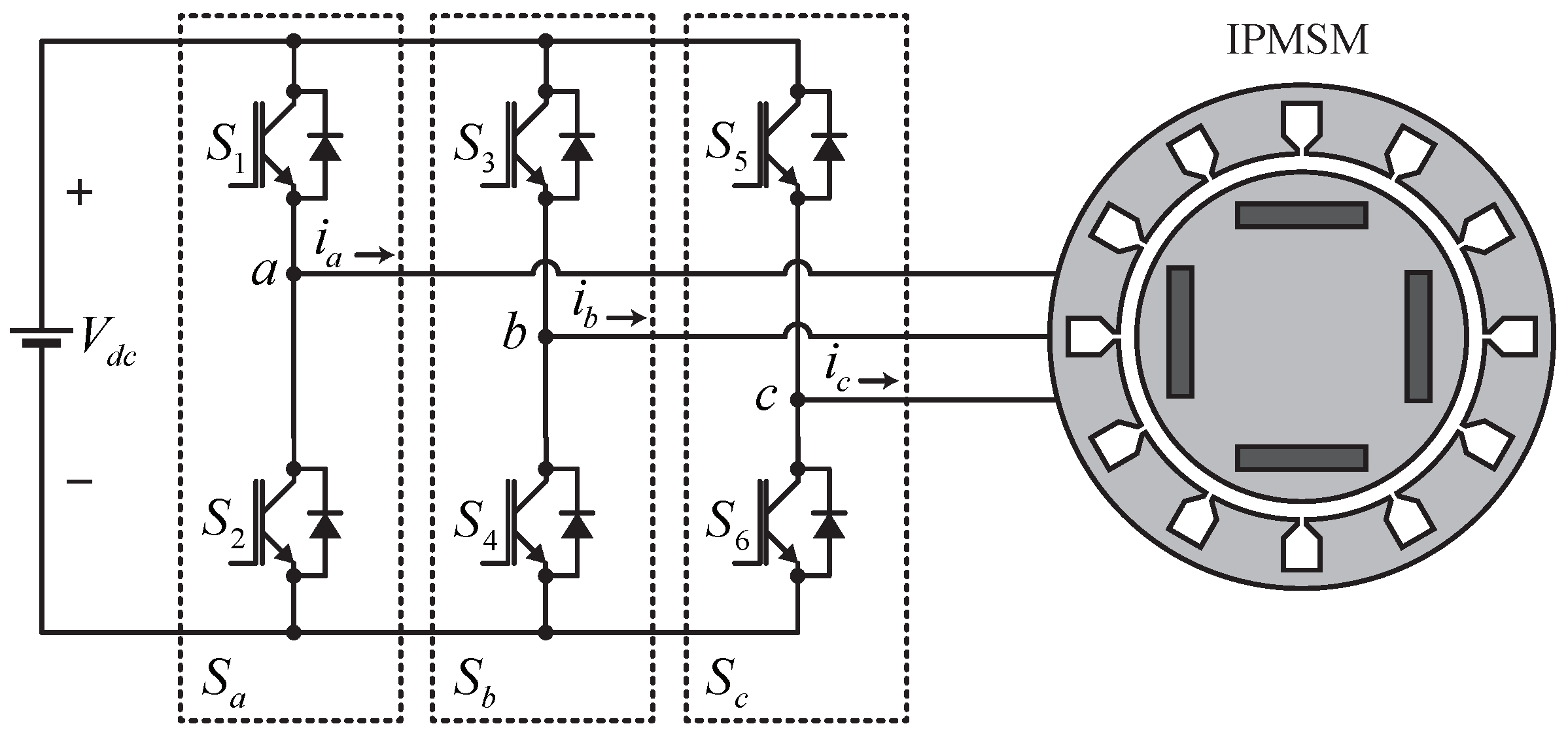
In this section, the mathematical interpretation of the salient-pole PMSM considered in this study is described. The three-phase two-level voltage source inverter (VSI) topology is shown in Figure 1. It is employed to control voltages across the drive by utilizing space vector pulse width modulation (SVPWM), which can achieve more DC voltage utilization and can reduce harmonic distortion compared with other switching techniques.
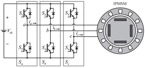
Figure 1.
Three phase two-level topology VSI fed IPMSM.
2.1. Dynamic Model of IPMSM
Continuous-time electrical and mechanical models of the salient-pole PMSM in the synchronous reference frame were employed in this study and are defined as follows [1]:
and
where and are the stator voltages in frame; and are the stator current along axes, respectively; is the stator-per phase resistanc; is the rotor shaft electrical speed. = , where represents rotor shaft mechanical speed and P denotes pole pairs, is the magnetic-flux linkage; and are the electromagnetic and load torque, respectively; B and J are the mechanical friction coefficient of load, and mechanical inertia, respectively.
2.2. Maximum Torque per Armature (MTPA)
Owing to the salient pole structure of IPMSM drives, the d-axis inductance cannot be equal to the q-axis inductance, i.e., . Hence, a reluctance torque component exists. Therefore, the implementation of maximum torque per armature (MTPA) becomes difficult owing to the complex relationship between the -axis reference currents. In this study, a simplified -axis reference current equation was derived based on known motor parameters. This helped overcome the complication problem in real-time implementation and also eliminated the use of look-up tables.
A simple equation for the d-axis reference was derived based on the q-axis reference current. Utilizing the given motor parameters, a linear relationship between the torque and q-axis reference current was derived. Considering
the equation for reference current can be expressed in terms of reference current as [28]:
For simplicity, the above d-axis reference current is expanded by a Taylor series expansion across a point reaching zero. Substituting the given motor parameters and neglecting high-order terms because of the smaller magnitude yield,
Here, is calculated by substituting drive parameters in (6) and expressed as
Equation (8) is expanded by the Taylor series expansion at . Eliminating the smaller magnitude term yields
3. Torque Pulsation Analysis
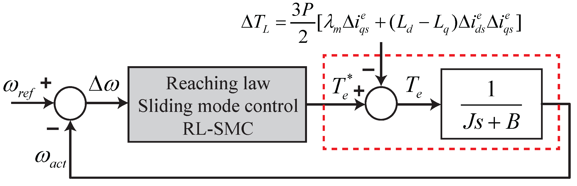
The periodic torque ripples that mostly occur in the IPMSM are separated into two groups: one results from the motor drive structure that causes, e.g., flux harmonics, cogging, and phase unbalancing, whereas the second group occurs because of drive control issues, e.g., gain mismatch, sensor offset error, delay occurring during processing, and the inverter dead time effect. From the motor drive transfer function, the electromagnetic torque is a function of the magnetic flux, reference current, and mechanical speed. Therefore, at a low operating speed range, the shaft speed oscillates at the same harmonic frequency as that of the change in the electromagnetic torque. This affects the speed performance at steady state. Moreover, because of oscillation, the control performance of the motor drive degrades. A pictorial description of the speed control loop is presented in Figure 2. In this section, the effect of the generation of periodic torque ripple caused by various disturbances is discussed in detail.
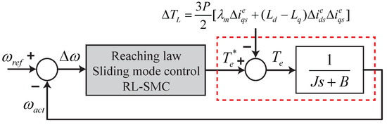
Figure 2.
Speed control block diagram.
3.1. Flux Harmonics
The presence of harmonics in the air-gap flux causes torque pulsation in the IPMSM. In a real drive system, it is difficult to achieve a pure sinusoidal flux density distribution across the air gap, which leads to torque ripples because of the interaction of the standard stator phase current with a nonsinusoidal flux density distribution across the air gap. In a three-phase system, the flux linkage between the drive phase current and magnet contains harmonics of the order 5, 7, 11,…, whereas, in the reference frame the 6th, 12th, and other multiples of the sixth harmonic for the corresponding torque appear and can be expressed as [21]
where , n is the multiple of the unexpected sixth harmonic, and is the DC component. The resultant torque is the summation of the DC component and the unexpected torque harmonic components. Therefore, periodic torque ripples occur owing to variations in the resultant torque caused by harmonics with time.
3.2. Current Sensor Offset Error
The inaccuracy of the current sensor occurs because of certain conditions caused by the controller. It is related to the presence of an inherent DC offset in the phase current measurements, which leads to pulsating torque ripples. Pulsating torque ripples occur at the fundamental frequency owing to a DC offset in the phase current measurement. The current sensor scaling error causes the torque of the motor drive to oscillate at twice the fundamental frequency. In the vector control system, the phase currents are measured as follows. First, using the current sensor, the current signals are converted into a voltage signal. Second, these voltage signals are converted to digital signals by employing a low-pass filter (LPF) and analog-to-digital converters (ADCs). The unbalanced supply voltage to the current sensors and many analog devices in the path for current measurement make unavoidable offset errors. The measured rotating -axis currents resulting from the DC offset errors are expressed as [29]:
where
is a constant angular displacement dependent on and which are the offset errors in the measured drive phase current, and is the electrical angle.
Assuming that the measured phase current from the sensor exactly follows the reference current obtained from the MTPA, the actual drive phase current is
Solving (14) for actual current in the presence of DC offset yields
where . (15) shows that the DC offset in the current measurement causes the torque of the motor drive to oscillate at the fundamental frequency. The speed of the motor drive also oscillates at the fundamental frequency because acts as a disturbance load for a closed-loop system and degrades the performance of the speed control.
3.3. Cogging Torque
The cogging torque is generated by the interaction between the magnetic flux and stator slots. Torque fluctuation occurs because the energy storage between the air gap of the motor stator slots was not fixed. Owing to the lack of efficient cogging torque models, a mathematical model to compensate for this is difficult to construct. In a previous report [30], it was shown that the cogging torque is a periodic function of the rotor shaft position. Cogging torque ripples appear at frequencies that are multiples of the number of stator slots per pole pair and the electrical frequency of the rotor. The cogging torque is directly related to the structural design of the motor body (e.g., winding distribution, skewing of the slot, and number of slots per pair), and the process of designing the motor drive is not repeatable, which means that once the motor drive is designed, it cannot be modified [21,30], which is not discussed further in this article.
In this study, a compensator was designed to reduce the torque harmonics that are produced owing to current measurement errors. Appropriate compensation signals are injected into the torque and dq reference. This method makes it possible to reduce the torque harmonics, leading to the minimization of the speed ripple. Different compensator schemes to address torque ripples have been proposed that enhance the robustness and steady-state error of the control system [24,25].
4. Design of Proposed Scheme
A nonlinear speed controller is presented that is designed based on the sliding-mode exponential reaching law, which is insensitive to external disturbances and shows robustness under parametric uncertainty. Furthermore, a compensation technique is introduced to minimize the speed ripple at low speed by modifying the reference -axis current and output of the speed control loop. This section comprises two parts. The ERL-SMC law is given first. Then, a compensation scheme for ripple reduction and for overcoming the disturbance injection is introduced.
4.1. Reaching Law Sliding Mode Control
SMC has several advantages over other nonlinear control schemes. It is easy to implement, is robust to variation, and has a fast response, which leads to excellent dynamic performance. However, a major drawback of this controller is that it causes chattering phenomena that excite high-frequency dynamics. One of the most important steps in designing SMC is to reduce the chattering issue, increase the robustness of the controller, and reduce the reaching time. To address these issues, a reaching law is designed based on an exponential term that modifies the change in the system states and sliding surface.
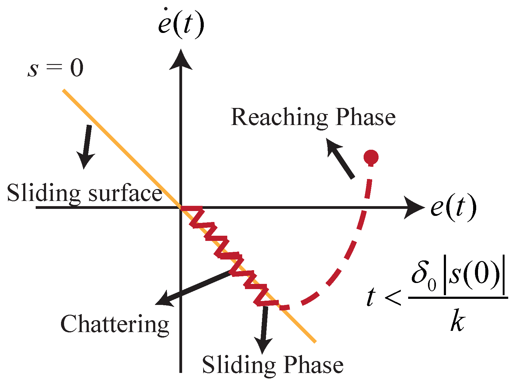
To design SMC, the sliding surface was designed, and a control input was constructed that forced the system trajectory toward the sliding surface, guaranteeing a condition reaching the sliding mode. The sliding mode mechanism in the phase plane is shown in Figure 3, and the nonlinear model to express the SMC is
where is the system state. A and B are nonlinear functions in term of x and B is invertible. The tracking error dynamics are given as:
where . The nonlinear system model to express SMC following the reaching law is given as:

Figure 3.
Sliding phase mechanism of the SMC.
Equation (18) ensures the stability of the sliding mode, whereas the convergence of the system trajectory to the sliding surface is related to the value of c in the sliding-mode surface. Once the sliding surface is selected, the next step is to select the switching controller u in such a way that it enables the error vector to reach the sliding surface and ensure the sliding mode reaching condition, which is expressed as
To satisfy (19), the conventional reaching law is
The reaching time required by the error vector to converge to the sliding surface is obtained by integrating (20) with respect to time, which is derived based on Lyapunov stability:
and
Therefore, the reaching time constant is
Equation (21) reveals that the reaching speed is increased by increasing the value of and excellent robustness can be achieved; however, this causes the chattering problem because the chattering increases with the increase in [31].
To overcome this interdependence between the reaching law and chattering level, an exponential reaching-law-based sliding-mode controller was designed. The reaching law was selected based on the choice of the exponential term that adapts to the change in the sliding-mode switching function. The reaching law is
where
Here, k is strictly positive integer, and . This exponential reaching law has no effect on the stability of the control design because is always strictly positive. (22) shows that, if decreases, the denominator of term reaches to , causing converge to . This means that the system trajectory reaches to sliding surface, in which decrease to zero under the control input, which helps to reduce the chattering level. However, the term is retained in (22), the chattering elimination capability is limited. In addition, if increases, then the term converges to which is greater than k, thus ensuring faster reaching time. The designed controller can easily adapt to the variation of the switching controller by allowing to vary between and 0. The reaching time in which the system trajectories approach the sliding surface is obtained by integrating (22), noticing that , and integrating the limit from , which yields
Because , the inequality expression is
Equation (24) is simplified as
Here, is always negative as and the term is strictly positive, which implies that and the robustness of the control increases with the fast-reaching speed of the sliding surface with the same gain. However, if the condition is set, then
Therefore, the reduction in chattering level is guaranteed as , which means that a fast reaching speed with less chattering can be achieved. As a result, the proposed approach minimizes chattering for the same reaching speed, which is a significant advantage over traditional sliding-mode control. For the speed control mechanism, the speed tracking error is introduced as which maintains the actual speed at the reference speed. The sliding-mode surface based on the aforementioned scheme is defined as
Taking the derivative of the tracking error and speed, the equivalent controller is calculated by setting yielding
where . Finally, the control law is the sum of (29) and (22), expressed as
Therefore, the control input is derived as
By utilizing (10) the torque reference is obtained.
4.2. Speed Ripple Compensation Scheme
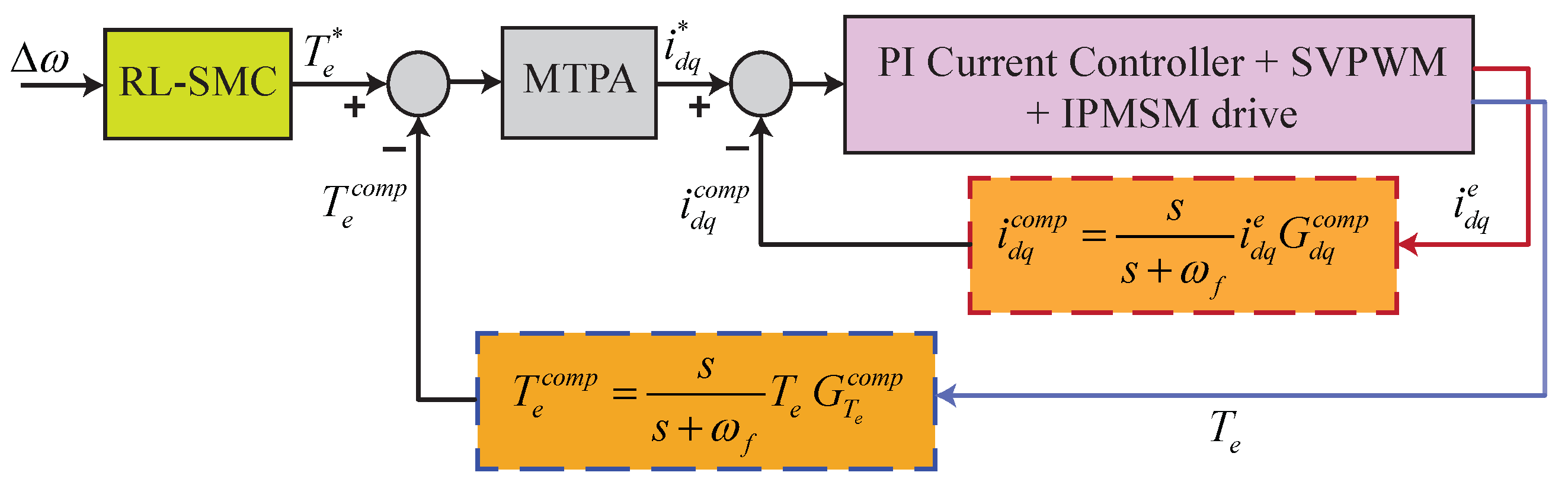
To minimize the speed ripple at a low operating speed, the reference -axis current and the output of the speed controller are modified by the current variations and disturbances in the electromagnetic torque, which minimizes the disturbance effect and increases the robustness under load variation. Figure 4 shows the structural design of the control scheme. The compensation signals are obtained by employing a high-pass filter. The mathematical expression derived for the -axis current compensation signals is
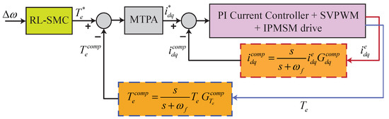
Figure 4.
Structural diagram of proposed compensation scheme.
The expression for the torque compensation signal is given as
where and are the filter cut-off frequency and the compensation gain. The cut-off frequency and gain are calculated using the compensator design for closed-loop transfer function and the sensitivity function given in [25].
5. Results and Discussion
A simulation model was developed to demonstrate the effectiveness of the proposed control design. An IPMSM drive with parameters given in Table 1, was utilized for performance evaluation under different test conditions.

Table 1.
Control System parameters.
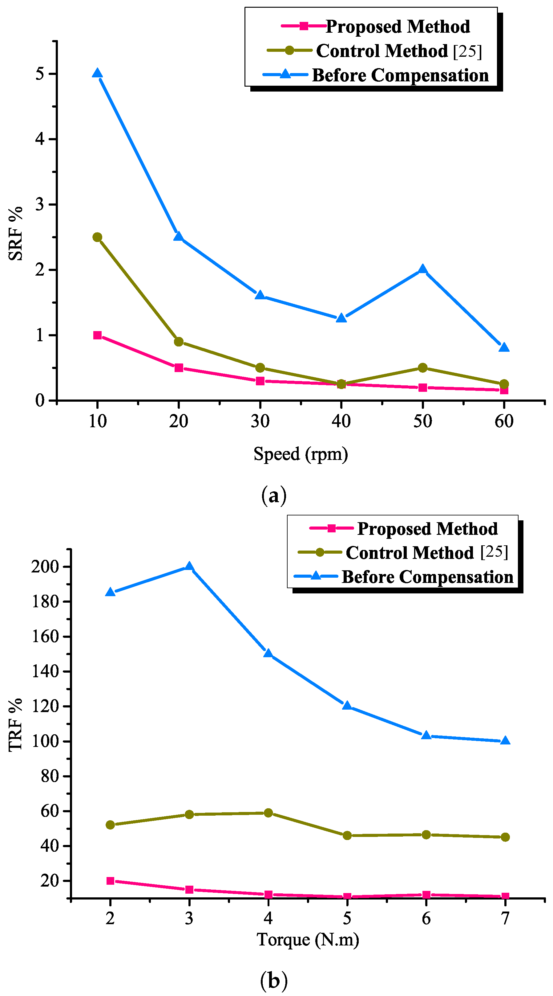
To demonstrate its effectiveness, a computer-based model of the proposed control design was implemented in MATLAB/Simulink, and a comparative study using a simulation tool was conducted to show the robustness and effectiveness of attaining excellent standstill performance under low-speed operating working conditions. The compensation gains for the electromagnetic torque and -axis current loop are set to and , whereas cutoff frequency is set to 50 rad/s. The optimal compensator gains should be chosen in such a way that the system’s stability and robustness are guaranteed while also obtaining the highest disturbance rejection capabilities. Figure 5 shows the rate of the ripple factor for the speed and torque of the IPMSM drive. The torque ripple factor (TRF) and speed ripple factor (SRF) are expressed as the ratio of the peak–peak torque and speed ripple to the rated torque and speed of the IPMSM drive, and they are derived as follows:
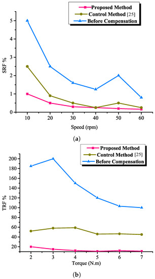
Figure 5.
Analysis of SRF for various speed and torque. (a) Speed SRF. (b) Torque SRF.
Figure 5a,b show the evaluation of the efficacy of the designed control algorithm with conventional control designs. For Figure 5a the speed is varied (10, 20, 30, 40, 50, 60) rpm under constant load torque of 7 Nm, whereas in Figure 5b the torque is varied (2, 3, 4, 5, 6, 7) Nm under constant speed of 50 rpm. The result reveals that employing the proposed control design ripple across the speed and torque effectively results in a reduction when the reference value increases. Compared with the conventional design, the ripples are greatly minimized with the proposed control design with increasing robustness, especially at low speed.
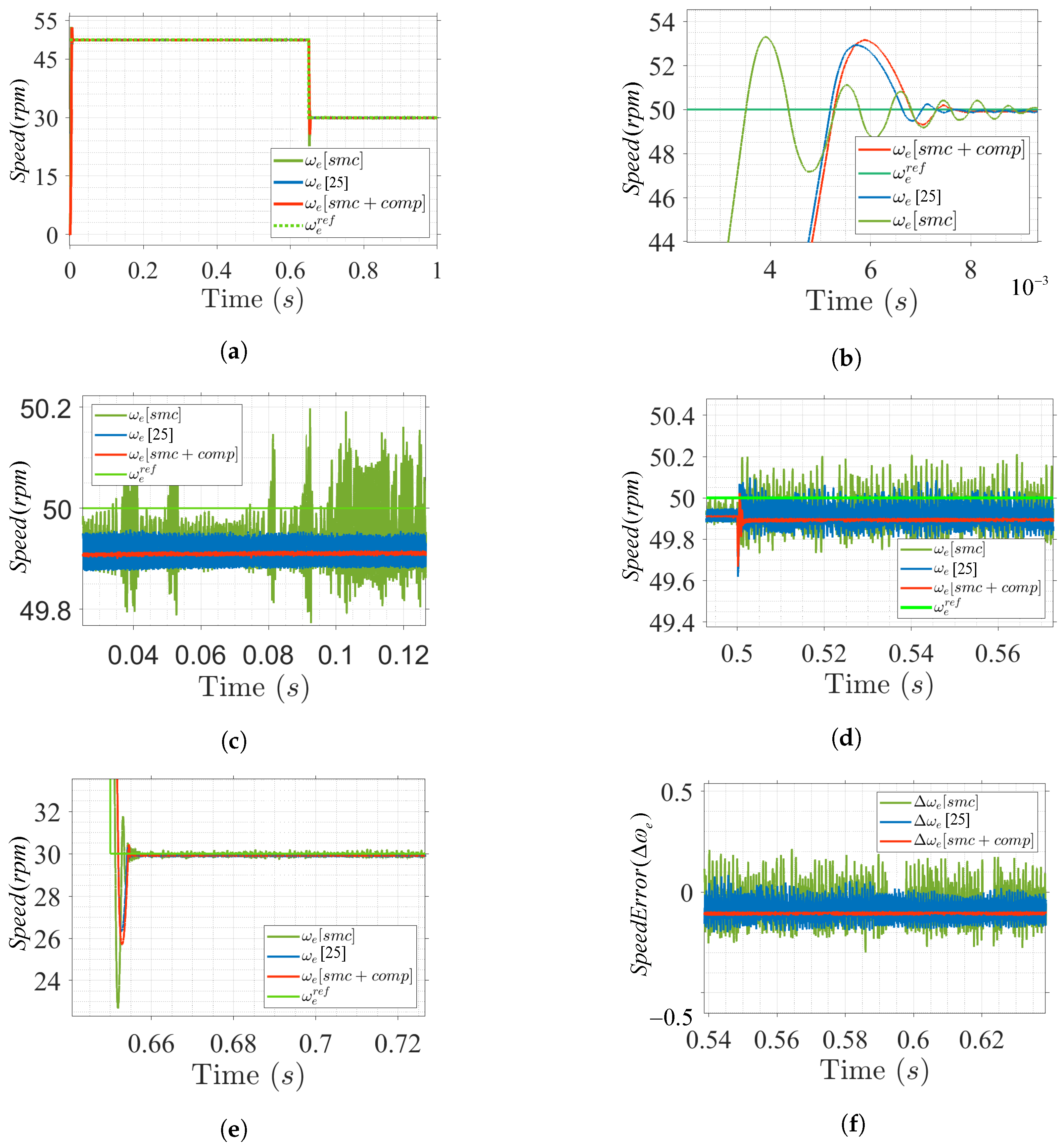
Figure 6 shows the speed response under various load conditions. A sliding-mode speed controller is applied to eliminate linear PI controllers that are sensitive to external disturbances. Initially, a reference speed of 50 rpm is applied under a load torque of 3 rpm that is shown in Figure 6a. Figure 6b,c shows the settling time and steady-state error of the drive, respectively. The settling time of the proposed design is fast, and the steady-state error is reduced. At 0.5 s, a load torque of 7 Nm is applied with a speed change from 50 to 30 rpm at 0.6 s. Figure 6d–f shows that, with load variation, the speed response is good, and the ripples across the speed at standstill are smaller than those in the conventional control design.
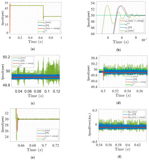
Figure 6.
Speed profile at low speed operating range under load variation. (a) Speed response. (b) Speed overshoot. (c) Speed steady-state response. (d) Speed during load applied. (e) Speed at 30 rpm. (f) Steady-state speed error.
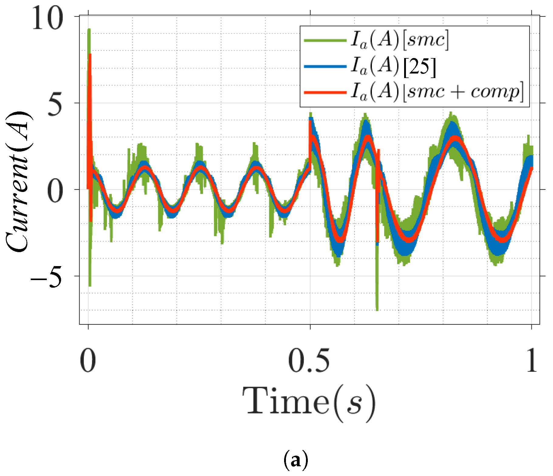
Figure 7a shows the a-phase current response of the IPMSM drive. The waveform of the a-phase current has a sinusoidal shape in the case of the proposed model, which indicates the regular operation of the IPMSM drive. A comparison of the a-phase current shows that the designed algorithm has a smaller current ripple, and the harmonic distortion is suppressed, ensuring the efficacy of the design model.
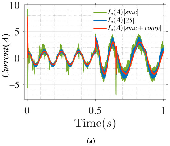
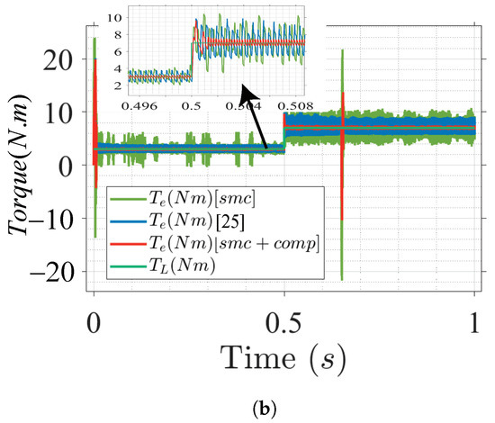
Figure 7.
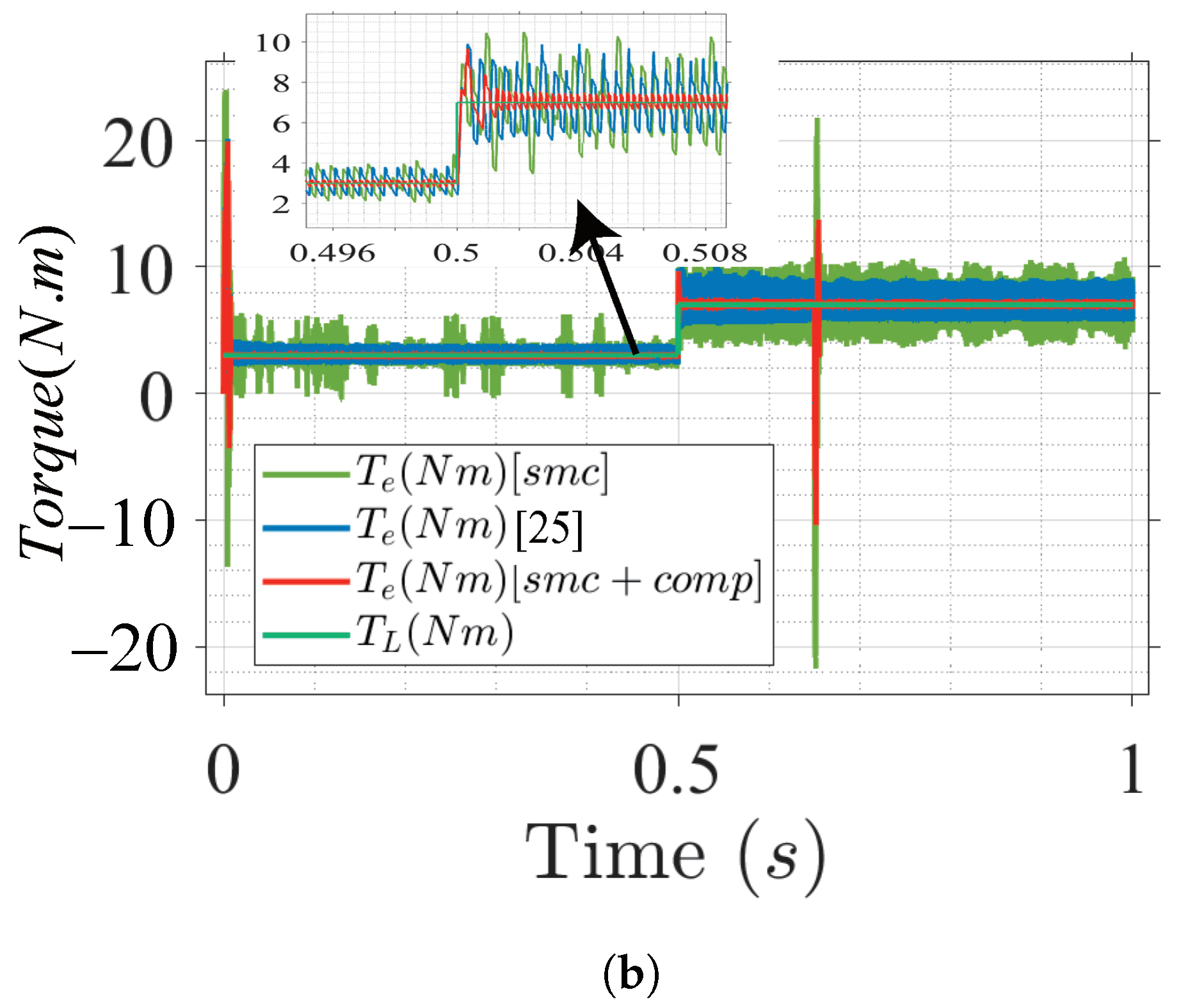
IPMSM current and torque response under nominal parameters with load step variation. (a) Motor phase current. (b) Torque response.
Figure 7b shows the response of the reference torque and the output electromagnetic torque across the drive. By employing the MTPA control scheme, the torque was obtained by utilizing the minimum current value. It can be seen that has a higher ripple in the conventional method, whereas ripples are reduced in the proposed control structure design.
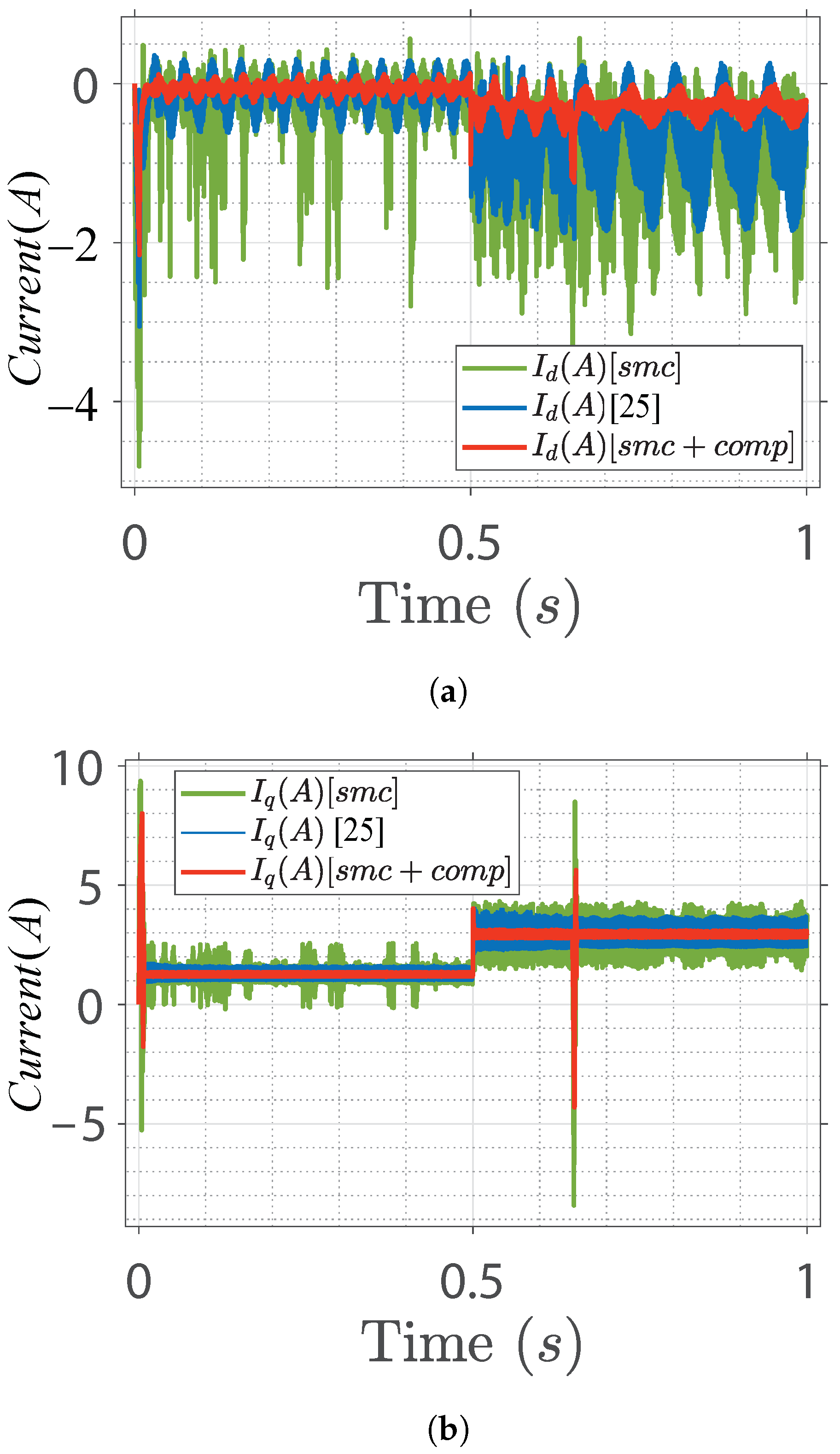
Figure 8 shows the drive phase current along the d and q-axis. Based on conventional methods, the d and q-axis currents show higher current ripples, whereas the proposed control design shows minimum ripples across the d and q-axis current.

Figure 8.
Reference output state’s variable. (a) D-axis current. (b) Q-axis current.
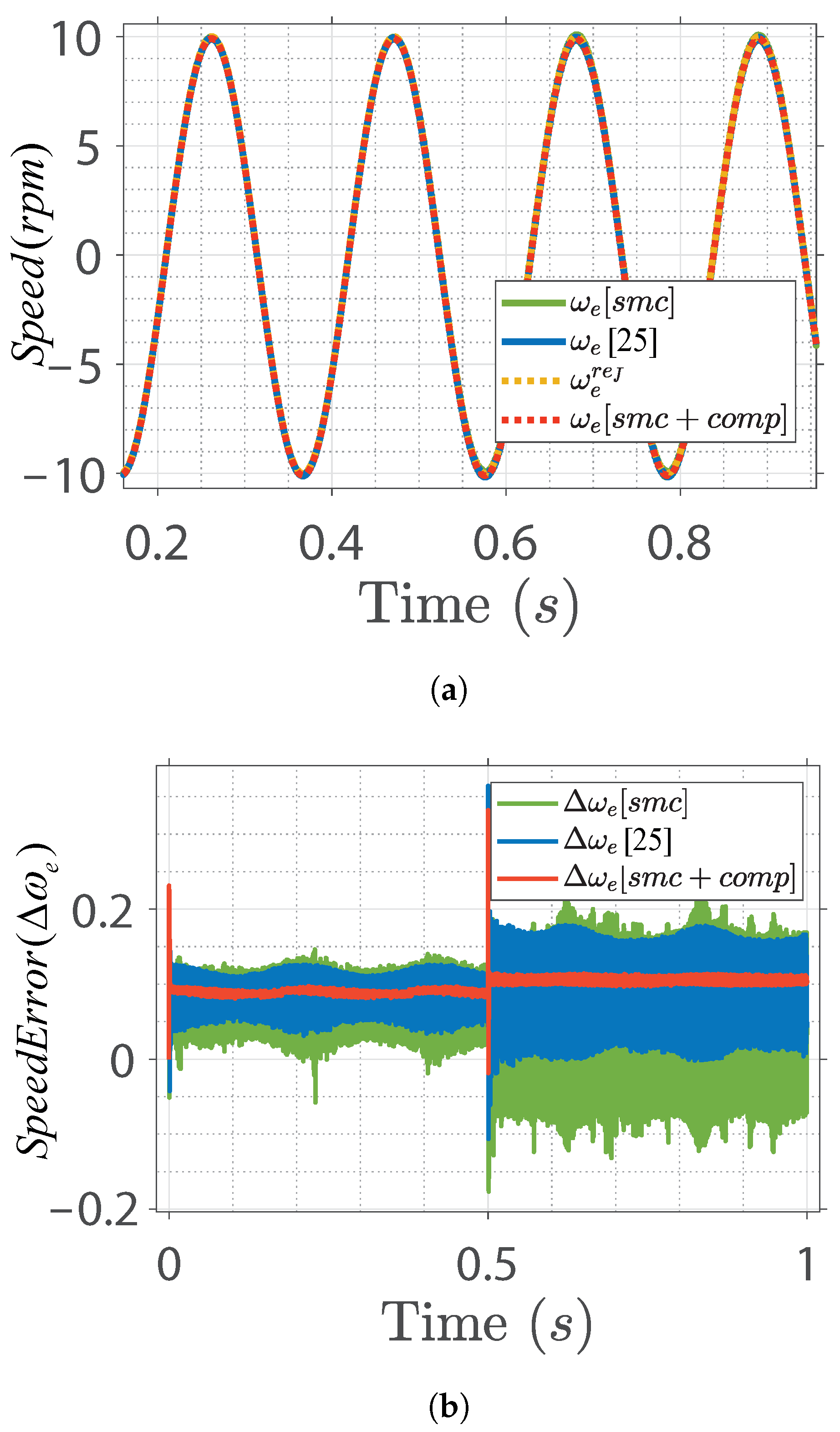
To verify the robustness of the proposed control design, the speed convergence characteristic of the IPMSM was simulated based on a sinusoidal reference speed input with an amplitude of 10 rpm and a frequency of 30 Hz. The sinusoidal speed response and error curves based on different control designs are shown in Figure 9. The convergence of the actual to the reference speed with minimal error is observed in the proposed design. This implies that the steady-state error of the control system is minimized when the proposed control method is employed. Moreover, the controller has excellent dynamic performance and can effectively increase the robustness of the system by resisting the effect of load disturbance, which increases the overall performance of IPMSM speed control under uncertainties and load variations. The qualitative performance analyzed between the conventional and the proposed control schemes is summarized in Table 2.

Figure 9.
IPMSM drive speed response under sinusoidal speed input. (a) Sinusoidal speed response. (b) Speed error.
Table 2.
Comparative performance of conventional and proposed control scheme.
6. Conclusions
An effective compensation method with a sliding-mode speed controller which reduces speed and torque ripples at low-speed operation is proposed. The SMC scheme makes the speed controller parameter independent. The main sources of torque ripple, the structure of the speed controller, and the compensation technique for minimizing the ripples in the speed control were discussed in detail. The proposed method is simple and does not require additional computational cost and can be applied to drive applications where low-order harmonics are undesired. The chattering of SMC is reduced by introducing an exponential reaching law that has the advantage of fast convergence and could adapt the variation of switching function, thus, increasing the robustness of the speed controller. The feasibility of the control structure was verified through simulation results under different conditions, e.g., variable low-speed, varied load, and sinusoidal speed reference input. A comparative study with the conventional control method was conducted, and the results show that the proposed controller effectively enhances the steady-state and dynamic performance of SPMSM especially in the low-speed regions, e.g., smaller speed ripples, smaller steady-state error, and faster transient response.
Author Contributions
M.U. designed the proposed control, performed the simulation, and wrote the paper. J.K. analyzed data and wrote the paper. All authors have read and agreed to the published version of the manuscript.
Funding
This study was supported by a research fund from Chosun University, 2019.
Institutional Review Board Statement
Not applicable.
Informed Consent Statement
Not applicable.
Conflicts of Interest
The authors declare no conflict of interest.
References
- Nam, K. AC Motor Control and Electric Vehicle Applications; CRC Press: New York, NY, USA, 2010; pp. 133–158. [Google Scholar]
- Song, X.; Fang, J.; Han, B. High-precision rotor position detection for high-speed surface PMSM drive based on linear hall-effect sensors. IEEE Trans. Power Electron. 2016, 31, 4720–4731. [Google Scholar]
- Wu, S.; Zhang, J. A robust adaptive control for permanent magnet synchronous motor subject to parameter uncertainties and input saturations. J. Electr. Eng. Technol. 2018, 13, 2125–2133. [Google Scholar]
- Feng, G.; Lai, C.; Kar, N.C. Practical testing solutions to optimal stator harmonic current design for PMSM torque ripple minimization using speed harmonics. IEEE Trans. Power Electron. 2018, 33, 5181–5191. [Google Scholar] [CrossRef]
- Tursini, M.; Parasiliti, F.; Zhang, D. Real-time gain tuning of PI controllers for high-performance PMSM drives. IEEE Trans. Ind. Appl. 2002, 38, 1018–1026. [Google Scholar] [CrossRef]
- Yadav, D.; Verma, A. Performance analysis of permanent magnet synchronous motor drive using Particle Swarm Optimization technique. In Proceedings of the International Conference on Emerging Trends in Electrical Electronics and Sustainable Energy Systems, Sultanpur, India, 11–12 March 2016; pp. 280–285. [Google Scholar]
- Rovere, L.; Formentini, A.; Zanchetta, P. FPGA implementation of a novel oversampling deadbeat controller for PMSM drives. IEEE Trans. Ind. Electron. 2019, 66, 3731–3741. [Google Scholar] [CrossRef]
- Lee, J.S.; Lorenz, R.D. Robustness analysis of deadbeat-direct torque and flux control for IPMSM drives. IEEE Trans. Ind. Electron. 2016, 63, 2775–2784. [Google Scholar] [CrossRef]
- Wang, S.; Wan, S. Full digital deadbeat speed control for permanent magnet synchronous motor with load compensation. IET Power Electron. 2013, 6, 634–641. [Google Scholar] [CrossRef]
- Li, S.; Gu, H. Fuzzy adaptive internal model control schemes for PMSM speed-regulation system. IEEE Trans. Ind. Inform. 2012, 8, 767–779. [Google Scholar] [CrossRef]
- Bouguenna, I.F.; Tahour, A.; Kennel, R.; Abdelrahem, M. Multiple-vector model predictive control with fuzzy logic for PMSM electric drive systems. Energies 2021, 14, 1727. [Google Scholar] [CrossRef]
- Chai, S.; Wang, L.; Rogers, E. A cascade MPC control structure for a PMSM with speed ripple minimization. IEEE Trans. Ind. Electron. 2013, 60, 2978–2987. [Google Scholar] [CrossRef] [Green Version]
- Tu, W.; Luo, G.; Chen, Z.; Cui, L.; Kennel, R. Predictive cascaded speed and current control for PMSM drives with multi-timescale optimization. IEEE Trans. Power Electron. 2019, 34, 11046–11061. [Google Scholar] [CrossRef]
- Garcia, C.; Rodriguez, J.; Odhano, S.; Zanchetta, P.; Davari, S.A. Modulated model predictive speed control for PMSM drives. In Proceeding of the IEEE International Conference on Electrical Systems for Aircraft, Railway, Ship Propulsion and Road Vehicles and International Transportation Electrification Conference, Nottingham, UK, 7–9 November 2018; pp. 1–6. [Google Scholar]
- Gao, W.; Hung, J.C. Variable structure control of nonlinear systems: A new approach. IEEE Trans. Ind. Electron. 1993, 40, 45–55. [Google Scholar]
- Zaihidee, F.M.; Mekhilef, S.; Mubin, M. Robust speed control of PMSM using sliding mode control (SMC)—A review. Energies 2019, 12, 1669. [Google Scholar] [CrossRef] [Green Version]
- Fnaiech, M.A.; Betin, F.; Capolino, G.-A.; Fnaiech, F. Fuzzy logic and sliding-mode controls applied to six-phase induction machine with open phases. IEEE Trans. Ind. Electron. 2010, 57, 354–364. [Google Scholar] [CrossRef]
- Wang, L.; Chai, T.; Zhai, L. Neural-network-based terminal slidingmode control of robotic manipulators including actuator dynamics. IEEE Trans. Ind. Electron. 2009, 56, 3296–3304. [Google Scholar] [CrossRef]
- Li, S.; Zhou, M.; Yu, X. Design and implementation of terminal slidin gmode control method for PMSM speed regulation system. IEEE Trans. Ind. Inform. 2013, 9, 1879–1891. [Google Scholar] [CrossRef]
- Fei, Q.; Deng, Y.; Li, H.; Liu, J.; Shao, M. Speed ripple minimization of permanent magnet synchronous motor based on model predictive and iterative learning controls. IEEE Access 2019, 7, 31791–31800. [Google Scholar] [CrossRef]
- Qian, W.; Panda, S.K.; Xu, J.X. Torque ripple minimization in PM synchronous motors using iterative learning control. IEEE Trans. Power Electron. 2004, 19, 272–279. [Google Scholar] [CrossRef]
- Chan, C.C.; Jiang, J.Z.; Chen, G.H.; Wang, X.Y.; Chau, K.T. A novel polyphase multipole square-wave permanent magnet motor drive for electric vehicles. IEEE Trans. Ind. Appl. 1994, 30, 1258–1266. [Google Scholar] [CrossRef]
- Gebregergis, A.; Chowdhury, M.; Islam, M.; Sebastian, T. Modeling of permanent-magnet synchronous machine including torque ripple effects. IEEE Trans. Ind. Appl. 2015, 51, 232–239. [Google Scholar] [CrossRef]
- Kim, K.-C. A novel method for minimization of cogging torque and torque ripple for interior permanent magnet synchronous motor. IEEE Trans. Magn 2014, 50, 793–796. [Google Scholar] [CrossRef]
- Houari, A.; Bouabdallah, A.; Djerioui, A.; Machmoum, M.; Auger, F.; Darkawi, A.; Olivier, J.-C.; Benkhoris, M.F. An effective compensation technique for speed smoothness at low-speed operation of PMSM drives. IEEE Trans. Ind. Appl. 2018, 54, 647–655. [Google Scholar] [CrossRef]
- Ma, Z.; Saeidi, S.; Kennel, R. FPGA implementation of model predictive control with constant switching frequency for PMSM drives. IEEE Trans. Ind. Inform. 2014, 10, 2055–2063. [Google Scholar] [CrossRef]
- Mora, A.; Orellana, A.; Juliet, J.; Cárdenas, R. Model predictive torque control for torque ripple compensation in variable-speed PMSMs. IEEE Trans. Ind. Electron. 2016, 63, 4584–4592. [Google Scholar] [CrossRef]
- Usama, M.; Kim, J. Robust adaptive observer-based finite control set model predictive current control for sensorless speed control of surface permanent magnet synchronous motor. Trans. Inst. Meas. Control 2021, 43, 1416–1429. [Google Scholar] [CrossRef]
- Chung, D.W.; Sul, S.K. Analysis and compensation of current measurement error in vector-controlled AC motor drives. IEEE Trans. Ind. Appl. 1998, 34, 340–345. [Google Scholar] [CrossRef]
- Dosiek, L.; Pillay, P. Cogging torque reduction in permanent magnet machines. IEEE Trans. Ind. Appl. 2007, 43, 1565–1571. [Google Scholar] [CrossRef] [Green Version]
- Fallaha, C.J.; Saad, M.; Kanaan, H.Y.; Al-Haddad, K. Sliding-mode robot control with exponential reaching law. IEEE Trans. Ind. Electron. 2011, 58, 600–610. [Google Scholar] [CrossRef]
Publisher’s Note: MDPI stays neutral with regard to jurisdictional claims in published maps and institutional affiliations. |
© 2021 by the authors. Licensee MDPI, Basel, Switzerland. This article is an open access article distributed under the terms and conditions of the Creative Commons Attribution (CC BY) license (https://creativecommons.org/licenses/by/4.0/).