Abstract
Renewable sources of energy play a key role in the process of decarbonizing modern electric power systems. However, some renewable sources of energy operate in an intermittent, non-dispatchable way, which may affect the balance of the electrical grid. In this scenario, wind turbine generators must participate in the system frequency control to avoid jeopardizing the transmission and distribution systems. For that reason, additional control strategies are needed to ensure the frequency response of variable-speed wind turbines. This review article analyzes diverse control strategies at different levels which are aimed at contributing to power balancing and system frequency control, including energy storage systems.
1. Introduction
Supply and demand of active power must be balanced at any given time for achieving a stable operation of an electric power system. Otherwise, the stability and quality of the power system will become progressively worse, which may result in the disconnection of system components and, eventually, cause fault cascades and blackouts [1,2]. In order to stabilize the system frequency, power production must match consumption; this balance management is known as frequency control [3].
Synchronous machines have a natural capability to slow down frequency deviations because of the inertia of their rotating masses. Thus, when a significant loss of power generation occurs, the resulting frequency drop is slowed. As a consequence, additional power reserves can be deployed to re-establish the power balance while remaining within acceptable frequency deviation limits [4]. In contrast, most Wind Energy Conversion Systems (WECS) are connected to the grid through power electronic interfaces, which decouple the prime mover from the electric system and thus do not naturally provide frequency response [5].
According to the International Renewable Energy Agency (IRENA), achieving the Paris climate goals requires that global wind power energy share reaches 21% by 2030 and 35% by 2050, as shown in Figure 1 [6].
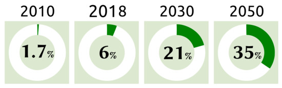
Figure 1.
Wind power in total generation mix: onshore and offshore wind generation share.
Currently, the increasing penetration of wind power and other renewable energy sources (RES) introduces concerns about the system security due to the inherent variations in the resulting rate of change of frequency (RoCoF). Therefore, actions must be adopted to avoid large RoCoF values when RES are massively used in the power system. Particularly, the effect of inertia of synchronous power-generating modules must be replaced with synthetic inertia, which would facilitate further expansion of RES [4,7,8]. Actually, during the last two decades, aggregated inertia has been reduced in Europe by around 20% in the last two decades because of grid-decoupled RES integration [9].
The system operator in each control area is responsible for balancing the grid from balancing service providers [10] whose power-generating modules must be capable of adjusting the active power output in response to a deviation of the measured system frequency [7]. Traditionally, the synchronous generators located in thermal power plants provide balancing services. However, some grid codes require explicitly that wind farms participate in frequency control tasks, such as EirGrid in Ireland and National Grid Code in the UK [8,11].
An initial classification in frequency control techniques for RES is presented in [12]. Figure 2 shows how this classification has been applied to variable-speed wind turbines (VSWT). Frequency control methods are split into two categories: with and without an energy storage system (ESS), such as secondary batteries, flywheels, pumped hydropower, or supercapacitors [13].
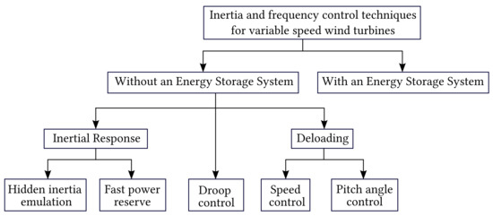
Figure 2.
Inertia and frequency control technique design for variable-speed wind turbines.
The rest of this review article is organized as follows. Section 2 discusses grid code requirements for frequency control and wind energy conversion systems, focusing on those with variable-speed turbines. Section 3 presents the techniques that have been proposed for the frequency control of variable-speed turbines at the generation-unit level. Section 4 explains different approaches aimed at providing frequency response from wind farms with and without energy storage systems. Section 5 provides an overview of the possibilities and challenges related to frequency control in power systems with increasing contribution of wind energy. Finally, some conclusions are drawn in Section 6.
2. Frequency Stability and Wind Power
2.1. Overview of Grid Code Requirements
Frequency stability is the ability of a power system to maintain steady frequency and restore active power equilibrium following a significant imbalance between generation and load, with minimum unintentional loss of load [14].
Figure 3 shows the activation of operating reserves on the event of a loss of generation in an electric power system [15].
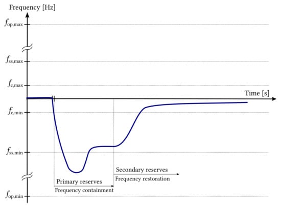
Figure 3.
Operating reserves activation in the event of a loss of generation in an electric power system.
Frequency control is usually divided into primary and secondary control [5] or, equivalently in the terminology used by European Network of Transmissions System Operators for electricity (ENTSO-e), “Frequency Containment Reserves” (FCR) and “Frequency Restoration Reserves” (FRR), respectively [10,15].
Primary reserve is the additional capacity of the network that can be automatically and locally activated by the generator’s own governor until a few seconds at most after a loss of load or generation. The purpose of primary reserve is to quickly restore the active power balance in the system by means of the so-called “droop control”. The generation increase or decrease is proportional to the error of frequency, and the frequency stabilization is achieved at a lower value (in the case of loss of generation) or at a higher value (in the case of loss of load) than the rated frequency of the system [15].
The purpose of secondary and tertiary reserves is to reset the electric system to its nominal frequency. The transmission system operator (TSO) is in charge of establishing the active power set-points in each control area.
At first, the frequency decreases with a slope that depends on the inertia of the system. If frequency falls bellow , primary operating reserves must be activated, increasing the mechanical power of the prime mover. Once the power balance is reached, the frequency remains constant but below the target frequency. Then, secondary and tertiary reserves are activated to restore the nominal frequency. The notation means the following:
- and are the frequency limits in which the system can work. These limits are imposed by the applicable grid code.
- and define the tolerance band for the quasi-steady-state frequency level, i.e., the level that is reached because of activation of only primary reserves by means of droop control. In practice, this means that if frequency falls below , the generator will activate 100 % of its primary reserves.
- and are the limits of the dead band for activation of the primary reserves.
European TSOs such as TenneT, which operates in the Netherlands and large parts of Germany, follow ENTSO-e recommendations and require that generators supply all of their operating reserves in 30 s at most [16].
Wind turbines supporting primary frequency control have been investigated by a number of authors [17,18,19,20].
There is a three-level hierarchy in control schemes for wind power generation to provide frequency response: wind turbine level, wind farm level and power system level [21]. Frequency containment reserves are provided at wind turbine level and wind farm level.
In order to get a general picture, Figure 4 shows the maximum and minimum limits for the frequency levels allowed during a period of time for TenneT, the Grid Code of Ireland and the National Grid Code of the UK.
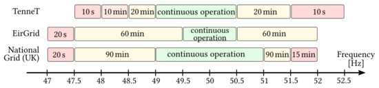
Figure 4.
Comparison of maximum times of operation as a function of grid frequency required by TenneT, the Grid Code of Ireland and the National Grid Code (UK).
Several performance indicators may be used to describe and to evaluate the system frequency response (SFR) [5]. Figure 5 shows a typical and idealistic SFR showing primary control only. The following indicators are depicted:
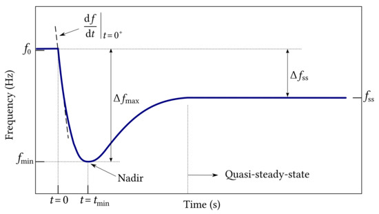
Figure 5.
System frequency response considering primary control.
- Rate of change of frequency at the time of the disturbance.
- Maximum frequency deviation is the absolute value of frequency deviation from nominal frequency, .
- Frequency nadir is the minimum frequency following a disturbance.
- Frequency nadir time is the time at which the frequency reaches the nadir.
- Quasi-steady-state deviation is the deviation between the nominal frequency value and the final value.
European Commission Regulation (EU) 2016/631 establishes harmonised rules for grid connection for power-generating modules [7]. This regulation divides the power-generating modules into four categories which depend on the voltage of the connection point and the maximum capacity according to a threshold specified by the relevant TSO. In continental Europe, power-generating modules with a rated power above 1 MW belong to type C or type D categories which have to support Frequency Sensitive Mode (FSM), meaning that they have to adapt their power output in response to a change in system frequency to assist with the recovery to target frequency.
Primary frequency control is based on set-points for frequency and power whose actual values are measured locally. Control actions are also local, taking place in each power-generation unit supporting frequency control regardless of the location of the disturbance. As droop control is a proportional controller, there remains an unavoidable frequency error that has to be managed at power system level to restore the target frequency [5].
Figure 6 is an adaptation of Figure 5 of EU Regulation 2016/631 to illustrate the FSM, where no deadband has been considered. The droop, expressed as a percentage, is defined as follows:
where is the maximum capacity or the actual power output when the FSM threshold is reached.
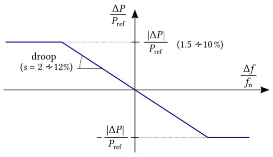
Figure 6.
Active power frequency response capability of power-generation modules in Frequency Sensitive Mode illustrating the case of zero deadband and insensitivity.
The droop characteristic must have a slope between 2 and 12% and, depending on the relevant TSO, it could include a deadband up to 0.5 Hz. There is also a tolerance of 10–30 mHz for frequency measurement error called “frequency response insensitivity” [7]. These parameters are shown in Table 1.

Table 1.
Parameters for active power frequency response in Frequency Sensitive Mode, specified by the European Commission.
In addition to the requirements regarding frequency containment reserves in FSM, EU Regulation 2016/631 introduces the concept of synthetic inertia, which may be crucial for system stability [15].
2.2. Inertia and Rate of Change of Frequency
In power systems with increasing wind power penetration, more pronounced frequency nadir and RoCoF events may occur. This presents a significant challenge for system operators [22].
Newton’s Second Law for a rotating electric machine is expressed as in Equation (2):
where J (kg m2) is the total moment of inertia of the system and (Nm) represents the balance between the mechanical torque impressed on the rotating mass by a prime mover and the electrical torque depending on the power exchanged with the system. The resulting torque, if different from zero, causes an angular speed deviation. In the absence of losses, it can be assumed that in a physical electrical system, the inertia is an effect proportional to torque imbalance and inversely proportional to the rate of change or rotating speed [4]. Equation (3) considers the total kinetic energy of the rotating masses.
Therefore, there is a relationship between power balance and speed deviation as expressed in Equation (4),
where the mechanical speed of the rotating mass has been approximated with the rated angular frequency of the grid, . Total equivalent inertia, H, is defined as the ratio of the kinetic energy of the rotating masses and the rated apparent power of synchronous generators in the power system as,
Equation (5) is also valid for a single synchronous generator under study. H is measured in seconds and it is an indication of the delivery time of the design power of the generator from only its kinetic energy. The typical inertia constants for conventional synchronous generators can range from 2 to 9 seconds [18,23].
Equation (6) shows that a power imbalance will cause an acceleration of rotating masses in the system, which is proportional to system inertia.
It follows that, if consumption of active power increases, frequency will decrease with a rate that will be higher the lower the inertia of the generator. Therefore, inertia is considered as an energy reserve that acts instantly and moderates the change in system frequency [8].
The rate of change of frequency (RoCoF) is the derivative of the power system frequency, . RoCoF is an important quantity that qualifies as the robustness of an electrical grid [4]. The instantaneous RoCoF just after an imbalance of power (caused by disconnection of a generator or by load tripping) and before the action of any control is calculated as follows,
where 0+ is the moment just after the power imbalance. For example, the Grid Code of Ireland allows a RoCoF up to 0.5 Hz/s for generation units connected to the network before December 2018. Significantly, it has been recently modified to facilitate the delivery of the 2020 renewable targets, and it currently allows a RoCoF up to 1 Hz/s as measured over a rolling period of 500 ms [8,24].
2.3. General Concepts about Harnessing Wind Energy
The mechanical power in the primary shaft of a wind turbine is given by the expression [25],
where is the power transported by the wind in an airstream whose section corresponds to the area swept by the blades of the wind turbine under study, as defined by Equation (9). is the coefficient of aerodynamic performance of the turbine.
is the density of the air, is the swept area and is the speed of the wind, supposedly constant in the airstream that we considered in front of the turbine and far enough from it.
Electric active power delivered to the grid can be expressed in terms of mechanical power of the turbine through a general efficiency factor, , as follows,
The turbine shaft torque is,
where is the rotational speed of the turbine. has a theoretical limit derived from a simple model based on the conservation of linear momentum of the particles of air. Its value is approximately 0.59 and it is known as the Betz limit. In a more elaborate model, which includes wake rotation and conservation of angular momentum, the theoretical maximum depends on the speed of rotation of the turbine, and it approaches Betz limit as rotation speed increases [25].
However, more realistic models show that increases only up to an optimal speed of rotation and optimal pitch angle ( ), as Figure 7 shows.
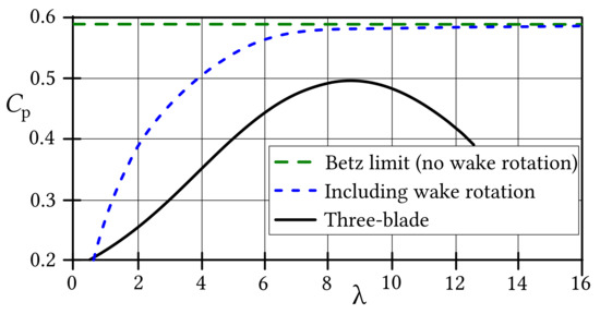
Figure 7.
Operation limits of wind turbines from simplified models and typical horizontal axis three-blade turbine.
An expression proposed in [26] for for three-blade turbines is the following,
where
, also known as TSR, is the blade tip speed to wind speed ratio,
where is the radius of the area swept by the blades.
Coefficients to depend on the wind turbine under study. The authors in [27] show a similar expression with numerical coefficients based on a model found in Matlab/Simulink. A review of mathematical models of the coefficient of performance as a function of TSR and pitch angle can be found in [28].
This implies that for a given wind speed, there is an optimal rotation speed that extracts the maximum power from the wind.
The power curve of a wind turbine generator (WTG) represents the active power output as a function of wind speed (see Figure 8). The WTG begins to generate power when the wind speed reaches the cut-in value. For the rated wind speed, the generator produces its rated power. If the wind speed gains the cut-out speed, power generation is canceled in order to prevent defects and damages [25]. Theoretical power curves, assuming ideal conditions, are supplied by manufacturers [29]. A complete overview on wind turbine power curve modeling can be found in [30].
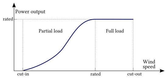
Figure 8.
Typical power curve of a wind turbine generator.
At the partial load operation region, the pitch angle is maintained at 0 (optimal pitch) and the turbine is operated at optimal rotor speed for maximum aerodynamic efficiency in order to maximize the power extracted from the wind. This control technique is known as the maximum power point tracking algorithm (MPPT). The optimal aerodynamic curve is usually characterized in a lookup table in the controller of the machine side converter [15,31,32]. At full load operation, the pitch angle is increased to lose aerodynamic efficiency in order not to exceed the rated power of the generator [33,34].
An analytical modeling of wind speed distribution in wind turbine arrays including small onshore and large offshore wind is developed in [35].
2.4. Variable-Speed Wind Turbines
According to the capability of speed variation, the gearbox and the electric generator, horizontal axis, three-blade wind turbine-based WECS can be roughly classified into four types [36,37]. For a more complete definition and variants of this classification, see [38].
- Type 1: Fixed speed wind turbine, with multiple-stage gearbox and squirrel cage induction generator (SCIG).
- Type 2: Limited variable-speed wind turbine with multiple-stage gearbox and wound rotor induction generator (WRIG).
- Type 3: Variable-Speed Wind Turbines (VSWT) using doubly fed induction generator (DFIG) and partial converter.
- Type 4: VSWT with direct drive or single-stage gearbox and full converter.
Inertia from fixed-speed WECS cannot be controlled and, as the authors in [39] demonstrate, it is negligible compared to a type 3 WECS of the same rated power. Type 2 WECS use external resistors connected to the rotor to achieve a limited speed regulation for maximizing the electrical torque and power. However, the use of external resistors for this purpose is now considered obsolete [40]. This review is focused on type 3 and type 4 Variable-Speed Wind Turbines, which are capable of supporting primary frequency control and releasing the “hidden inertia” of the turbine [18].
Figure 9 shows the architecture of types 3 and 4. Both of them use back to back (B2B) converters. Type 3 features a partial-scale B2B converter (rotor side and grid side) and a DFIG, whereas type 4 uses a full-scale B2B converter (machine side and grid side) connected to the stator of a synchronous machine (SM) or an induction machine (IM) with a squirrel-cage rotor. Some type 4 WECS are directly driven and do not include a gearbox.
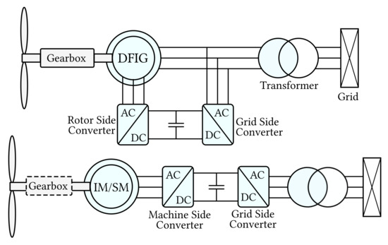
Figure 9.
Typical architectures of Variable-Speed Wind Turbines. Top: Type 3, variable-speed with multiple-stage gearbox, DFIG and partial-scale converter. Bottom: Type 4, variable-speed with optional direct drive, IM or SM, and full-scale converter.
The quadrature-phase slip ring model of a doubly fed induction generator, along with its overall control structure, is described in [41,42,43]. Several authors have used this model to develop and enhance the field-oriented control (FOC) technique to achieve an optimal power tracking including frequency response. FOC, also known as vector control, sets a two-dimensional rotating reference, called d-q, whose direct axis is usually aligned with the stator magnetic flux. Under this scheme, the torque and the active power are proportional to the q-axis component of the rotor current, whereas the q-axis component is used to regulate the reactive power flow [27,40,44,45,46,47,48,49,50,51,52,53,54,55,56]. Figure 10 depicts the control of a DFIG with some of the additional controllers discussed in this article. colorblue In this manuscript, the asterisk sign (*) next to a variable means “reference value”.
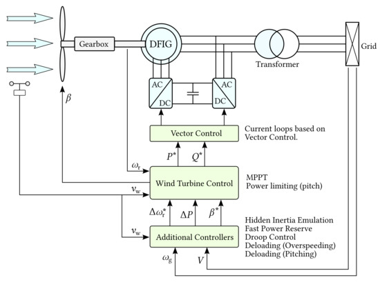
Figure 10.
Control architecture in a type 3 WECS featuring a doubly fed induction generator.
Modeling WECS with full-scale converters has also been covered in a number of articles [57,58,59,60,61,62,63,64,65].
3. Frequency Control Techniques for Variable-Speed Wind Turbines
3.1. Inertial Response
The kinetic energy of the wind turbine (WT) is used when the frequency deviation exceeds the frequency response insensitivity [2]. The power released to or absorbed from the grid is known as the inertial response. The inertial controller is implemented by two methods: hidden inertia emulation and fast power reserve emulation. Both methods have an inertial response of a very short duration, i.e., up to 10 s since the beginning of the frequency disturbance [5,63].
Eriksson et al. [66] make a similar distinction and use the terms “synthetic inertial response” and “fast power reserve”. Synthetic inertial response corresponds to the controlled response from a grid-decoupled generating unit to mimic the instantaneous exchange of kinetic energy from a synchronous machine with the power system. Synthetic inertial response is proportional to RoCoF. On the other hand, “fast frequency response” is the controlled contribution of active power that has a quick response to frequency deviation. The response can be proportional to this deviation, or it can react following a predetermined schedule [21].
Lack of control over the primary energy source prevents continuous power regulation. However, during the first 2 or 3 s, the inertial response control is almost immediate. The fast response capability associated with variable-speed wind turbines can be used to improve the transient performance of current frequency regulation procedures for conventional generation units [67]. The initial frequency support mitigates the frequency nadir, matching or even exceeding the performance of a conventional generator, but after the nadir is reached, the frequency recovery is inferior since excessive deceleration of the wind turbine must be prevented [57].
The impact of inertia response on wind turbine dynamics is under research. Guo and Schlipf develop a spectral model of grid frequency and propose a notch filter to reduce the impact on the shaft loads [68]. Ochoa and Martinez propose the study of the transfer function that represents the dynamic response of primary frequency control [69].
3.1.1. Hidden Inertia Emulation
The aim of the synthetic inertia controller, or hidden inertia emulation, is to release the kinetic energy from the wind turbine [18,39]. As Figure 11 shows, the output of this controller ( ) is combined with the output of the MPPT algorithm to form the active power control signal [5].
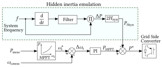
Figure 11.
Controller for releasing hidden inertia.
The synthetic inertia controller helps to reduce RoCoF and to increase the frequency nadir. It releases considerably larger kinetic energy from the wind turbine compared with fixed-speed turbine with induction generator [39].
Gonzalez-Llongat considers three different activation schemes for hidden inertia emulation [70]:
- Continuously operating. This is an unrealistic control scheme and it is mentioned only for comparison purposes.
- Under-frequency trigger. This activation scheme produces a trigger signal if the measured frequency is below the frequency threshold.
- Maximum RoCoF trigger. Similarly to RoCoF relays, the trigger signal is activated if is below a certain threshold.
3.1.2. Fast Power Reserve
The fast power reserve controller is designed to provide a short-term inertial response [5,19,63,71,72]. It can significantly raise the frequency nadir [66].
Fast power reserve ( ) is inferred from the kinetic energy stored in the wind turbine,
where is the time elapsed since the frequency disturbance, is the initial speed and is the rotational speed corresponding to .
This controller acts on the rotor speed signal to allow kinetic energy from the turbine to be released. The change in the speed signal for fast power reserve is obtained as follows,
The block diagram in Figure 12 represents the general implementation of fast power reserve emulation.
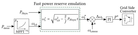
Figure 12.
Fast power reserve emulation controller.
Ochoa and Martinez develop a control strategy to operate a DFIG-WT at an optimal power point to contribute inertial response to a large-scale power system. Their simulation shows that the inertial contribution of the wind turbine improves the frequency response of the system [73].
3.2. Droop Control
The droop controller is a steady-state power-frequency characteristic as depicted in Figure 13. It yields an active power change proportional to the frequency deviation [5].
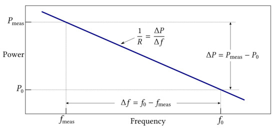
Figure 13.
Frequency droop characteristic.
Figure 14 shows an implementation of the frequency droop control for a VSWT [5,18]. When the wind turbine works at its maximum power, the power increase ( ) is obtained from the kinetic energy of the rotation masses. In this case, there is a risk of reducing the turbine speed too far which would force it out of the stable operating range [17].
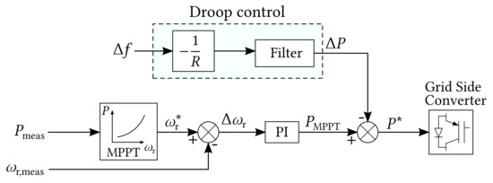
Figure 14.
Frequency droop control for variable-speed wind turbines.
To avoid turbine stall, the droop controller can be combined with a deloading control: The turbine is operated at a suboptimal operating point in order to have available power in the wind ready to be delivered in response to a system frequency drop [5].
Zhang et al. propose a frequency control with a prediction-based droop coefficient under real-time spot market rules. The droop coefficient and thus the power reference are updated at every bidding interval by using near-term prediction of wind power and grid frequency [74].
Droop control in weak power systems with reduced inertia are considered in [75].
3.3. Deloading
As mentioned in Section 2.1, wind power generation-units and, more generally, wind farms are required to assist with the recovery of target frequency by ramping their output up and down according to grid code requirements. However, hidden inertia emulation and fast power reserve can only give a short-term frequency control. This means that wind turbines have to be operated in a deloaded mode or, alternatively, use a suitable energy storage system. The former can be achieved by means of two methods: rotor speed control (overspeeding) and pitch angle control (pitching) [15,76] (see Figure 15). According to the research in [77], overspeeding has a better performance but a narrower regulation range than pitching.
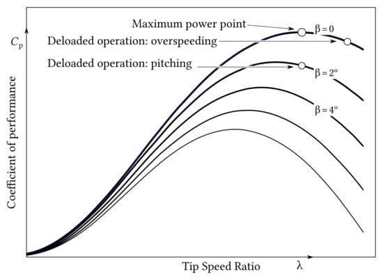
Figure 15.
Deloading techniques: overspeeding and pitching.
3.3.1. Speed Control
Figure 16 depicts the optimal power curve for different wind speeds at partial load operation and some deloaded curves based on overspeeding techniques [15]. Instead of working at the optimal curve, the target operation points lie on a deloaded curve corresponding to the requested power margin as Equation (18) shows,
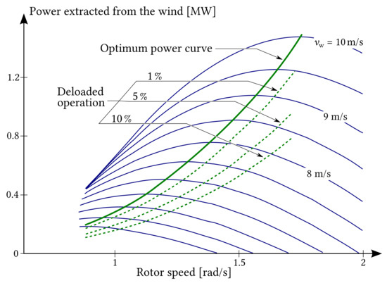
Figure 16.
Deloaded operation by means of speed control for a 1.5 MW DFIG-based wind turbine.
Deloading by overspeeding to achieve power reserve for participation in frequency control is adopted in [20,78,79,80,81,82].
Figure 17 shows a traditional overspeeding controller in which deloaded operation point is conditioned by the droop control [5].
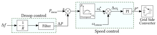
Figure 17.
Droop and speed controllers.
3.3.2. Pitch Angle Control
Increasing pitch angle for deloading purposes is a well-known technique [20,83]. The pitch angle controller response is slow because of its high mechanical time constant and causes fatigue load. The pitch angle controller is usually coordinated at the wind farm level [33,84,85]. The traditional pitch angle controller is depicted in Figure 18.
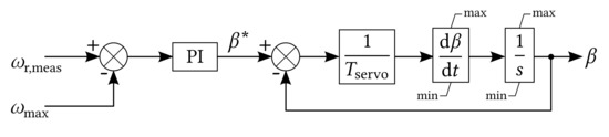
Figure 18.
Traditional pitch control.
3.4. Combination of Control Strategies
Depending on the wind speed level, either pitching or overspeeding is more suitable to deload the wind turbine. In the low wind speed range, overspeeding techniques are applied. For a wind speed higher than the rated speed pitch control is used not only for limiting the power output but also for applying deloading strategies. For a wind speed close to but below rated speed, a combination of overspeeding and pitching techniques can be used [15].
Luo et al. note that pitching shows a slow response and overspeeding has a narrow regulating range. In order to improve the regulation performance of the deloaded wind turbine, they developed and simulated a coordinated active power control strategy combining pitch angle control and speed control [86].
Traditional deloading techniques rely on the measured wind speed, but the accuracy of this measurement, or lack thereof, affects the estimates of available reserve. This may be somewhat avoided by carefully selecting a minimum droop [80]. However, Boyle et al. show that wind turbines can provide linear steady-state frequency-droop control by overspeeding without the need of measuring wind speed [82].
The coordinated control of inertia emulation, droop control, rotor speed control and pitch angle control enhances frequency control and damps the frequency oscillations effectively [79]. Alsharafi et al. [81] compare the performance of different methods in the full range of wind speed, both separate and combined, through simulations. They conclude that the best control performance in terms of RoCoF and frequency nadir is inertia emulation in combination with pitch control.
Other contributors make a similar classification in frequency control methods: Sonkar and Rahi [87] classify the control methods as “Inertial control”, “Droop control”, “Rotor speed control”, “Pitch angle control”, “Coordinated control” and “Other techniques”, while the review article in [88] distinguishes between “temporary energy reserves” (including synthetic inertia control and fast power reserve) and “persistent energy reserves” which means deloading by means of rotor speed control or pitch angle control.
Etxegarai et al. simulate the frequency response for under-frequency and over-frequency events in a small isolated power grid with a 76 MVA thermal power station and a 9 MW wind farm [89].
In [90], Hoseinzadeh and Chen develop a fuzzy logic-based LFC scheme for inertial support to system stability.
PD-type inertial response controllers are easy to implement, but they are vulnerable to measurement noise, which can undermine the performance of the inertial controller. Liu et al. developed and carried out experiments with a robust inertial control that is capable of rejecting the negative effects of measurement noise [91].
Hwang et al. propose a disturbance-adaptive short-term frequency support scheme for a DFIG-based VSWT. The adaptive gain changes depending on the RoCoF and rotor speed. They conclude that this technique can improve the frequency response while ensuring a stable operation [92].
4. Frequency Control Techniques at the Wind Farm Level
The effective frequency support from a wind farm (WF) requires a hierarchical control structure. There are two major control systems at the WF level: Central Control and Local Control. The Central Control regulates the active power of the WF by sending set-points to all WTs and the ESS, if available. The Local Control regulates the active power output at each WT and ESS and sends back information to the Central Control [5].
Figure 19 depicts the control hierarchy at the wind farm level. The active power command is received by the Central Control which distributes to the local controllers of wind turbines and ESS units [21].
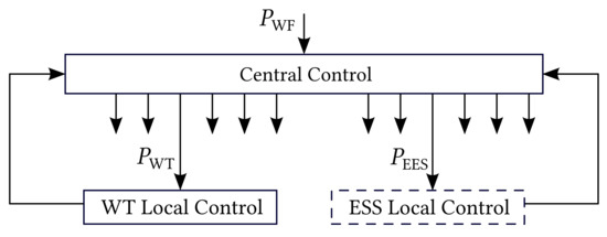
Figure 19.
Control hierarchy at the wind farm level.
4.1. Proposed Solutions without an Energy Storage System
Many modeled wind farms in the literature do not include an ESS [77,93,94,95].
For example, Ghosh et al. propose a farm control framework for primary frequency and inertial response for a high wind penetration power system supporting frequency regulation during subsynchronous and super-synchronous operation of the wind farm [96]. Dong et al. propose a fully distributed power regulation method for DFIG-based wind farms in which wind turbines share the load based on local information in order to guarantee that overspeeding control takes priority [97].
Fast response and avoiding frequent regulation of pitch angles is the motivation behind the control system designed in [98], where Zhang and Fang propose a coordinated deloading strategy at the wind farm level that meets their expectations.
The power system in Rhodes Island (Greece) is an autonomous power system with high wind penetration and different types of wind turbines whose primary frequency control has been evaluated in [99].
In this article [100], the authors propose a variable droop control strategy for wind farms that considers optimal rotor kinetic energy. They simulate an optimized scheduling reserve mode executed by the wind farm control center.
4.2. Proposed Solutions with an Energy Storage System
As depicted in Figure 20, there are two configurations for energy storage systems (ESS) [5]:
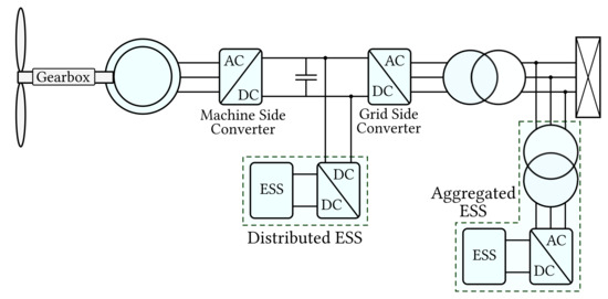
Figure 20.
Configurations of energy storage systems at the wind farm level: distributed ESS and aggregated ESS.
- Distributed ESS: Small, connected to the DC bus between the two converters on each VSWT.
- Aggregated ESS: Large, connected to the grid.
An ESS can help to provide frequency response. For example, Liu et al. designed a fuzzy logic controller to find the minimum rated power for an ESS when a sudden imbalance of active power takes place, and they found that an ESS with a power of about 5% of the rated power of the wind farm can provide similar short-term frequency response capability to that of synchronous generators of the same power as well as better frequency response under small disturbance [101].
There are different technologies for energy storage which can be applied to wind farms or to power systems with high wind power penetration [13,102,103,104,105,106]. An overview of the current state of energy storage from a sustainability perspective can be found here [107]. This review article focuses on the following ESS:
- Pumped Hydro Storage (PHS);
- Battery-based Energy Storage System (BESS);
- Flywheel Energy Storage (FES);
- Superconducting Magnetic Energy Storage (SMES);
- Supercapacitors (SC).
PHS is the largest and most mature energy storage technology. Martínez-Lucas et al. evaluate the capacity of an isolated hybrid wind-hydro power plant to contribute to frequency stability [108]. The proposed control strategies and adjustment methodology have been applied to the El Hierro power system [109].
BESS are maturing with falling prices and could play an important role in the path to decarbonization [110]. Particularly, systems based on lithium-ion batteries have evolved very quickly. They present a wide range of cell technologies and system architectures already available on the market [111]. Control strategies for BESS integration in microgrid applications including wind power have been developed in [112,113,114,115]. Zhang et al. propose a primary frequency controller with prediction-based droop coefficient involving a BESS that provides frequency response and reduces intermittency [74].
Johnston et al. propose a methodology for optimal sizing of ESS applied to Vanadium Redox Battery for participation in primary frequency support. They conclude that, for a 50 MW rated Wind Farm, a 5.3 MW/3 MWh ESS is the most profitable considering the frequency regulation in the UK market [116].
In the Australian National Energy Market, there is already a functional “grid-forming” battery that provides inertia and system strength, and some others are under construction [117]. In the UK, there is a rapid development and growth of BESS [118].
FES is based on transformation of electric power and kinetic energy of a rotating mass [119,120].
SMES application for smoothing wind power fluctuations by means of a superconducting coil has been researched in [121]. In [122,123], Li et al. propose a hybrid SMES-BES system.
SCs are ideal for short-term power exchange [124]. Frequency control support by means of supercapacitors on an isolated power system has been researched in [125].
5. Possibilities and Challenges for the Participation of Wind Power in Frequency Control
Negnevitsky et al. performed a risk assessment for power systems under high penetration of wind power [126]. Their conclusions are consistent with the problem discussed in this review article: an increasing participation of intermittent power generation leads to reconsidering the impacts of frequency disturbances, particularly in small or isolated grids.
The wind energy participation growth brings significant challenges in electric power systems in terms of frequency control, including wind speed measurement noise, lack of universal solutions, energy wasting, unexpected wind speed drops and modifications in the ancillary services market [127].
In Europe, the higher penetration of intermittent generators decoupled from the grid has reduced the total inertia by around 20% [9]. However, a recent report about inertia and system strength of Australia’s national energy market reveals that there is an economical alternative to the inertia provided by traditional generators: grid-forming batteries [117].
5.1. Wind Speed Measurement Noise
The lack of precision in the measurement of wind speed affects the estimates of the available reserve. A possible solution to obtain more precise wind speed measurements would be using LIDAR (light detection and ranging) sensors. These sensors have been extensively used in meteorological applications with good results [25]. However, Simley et al. conclude that there are a number of barriers that prevent the widespread use of LIDARs for control purposes in wind power applications, including reliability and sensitivity to weather conditions [128].
5.2. Lack of Universal and Standard Solutions
Despite great efforts in research, there is still no standard method to enable frequency control in wind turbines. Actually, the need of frequency support by wind farms is very different in large grids and isolated systems.
The decision to make wind farms contribute to frequency control is also challenging. Neither the European Commission Regulation “establishing a network code on requirements for grid connection of generators” nor the current UK Grid Code refer explicitly to wind farms. Instead, they define a “power park module” as a set of generators non-synchronously connected to the grid, which are classified in four types, each with their own requirements for frequency and voltage control [7,11]. Another point of debate is to set a reasonable deloading ratio, which must consider the instant available power according to the current wind speed value. The UK Grid Code and the European Commission set a maximum power reserve up to 10% of the maximum power available for power park modules, depending on their type and operating conditions.
It is remarkable that the Grid Code of Ireland has been recently modified to allow a higher RoCoF [8].
5.3. Energy Wasting and Unexpected Wind Speed Drops
There is an intentional power curtailment whenever the wind turbine is operated deloaded (i.e., below its optimal operating point) to obtain primary reserves. Unexpected wind speed drops can also make frequency control difficult. A dedicated ESS not only would mitigate these problems but also would improve the production of WFs.
5.4. Modifications in the Ancillary Services Market
Increasing the penetration of wind power will affect the Balancing and Ancillary Services Markets which were designed for conventional generation.
5.5. Grid-Forming Batteries
Zuo et al. perform simulations that demonstrate that large-scale battery storage systems improve frequency containment [129].
Recently, large BESS based on lithium-ion cells have been installed in Australia, California and the UK, showing that this technology is applicable in large power systems.
Battery-based energy storage systems have a quick response and are reliable technology. They have a remarkable prospect in regulating system frequency, contributing to enhancing system stability and allowing for increasing wind power penetration [130].
6. Conclusions
As grid-decoupled RES penetration increases, traditional frequency control has to be rethought. This paper presents a review of control strategies for wind farms to contribute to power balancing and system frequency control.
First, a brief overview of the literature on the subjects of frequency stability, wind power, inertia and variable-speed wind turbines has been introduced. Secondly, the control techniques for the provision of frequency response proposed by different researches have been presented. These control techniques include the following:
- Hidden inertia emulation and fast power reserve, which try to mimic the short-term inertial response of synchronous generators by means of additional control loops.
- Droop control, a well-known technique which is widely used in traditional generation units for primary frequency control.
- Deloading techniques, including overspeeding and pitching.
- Strategies at the wind farm level, with and without energy storage.
As the provision of wind power is not fully controllable, droop control has to be combined with either a deloaded operation of the wind turbine or a dedicated energy storage system. Strategies on deloading the turbine have been presented. The authors conclude that operating the wind turbine at a higher-than-optimal rotation speed (overspeeding) has a good performance but shows narrow regulating range. On the contrary, modifying the pitch angle to intentionally lose aerodynamic efficiency has a better regulating range, but it is slower and it could cause fatigue load. The application of both strategies highly depends on the wind speed. Unfortunately, the noise of the wind measurement introduces a negative effect that recent investigations try to address.
This article also discusses different frequency control techniques at the wind farm level and presents different approaches found in the literature. Some of them involve dedicated energy storage systems implemented by means of different technologies such as pumped hydro storage, battery-based energy storage, flywheels, superconducting magnetic storage and supercapacitors.
Energy storage is an alternative for deloading techniques in order to provide frequency response. Particularly, systems based on lithium-ion secondary batteries are gaining attention with a quick growth of the market. They may become an option in the future depending on the price.
Author Contributions
Conceptualization, P.F.-B., O.B. and I.C.; methodology, P.F.-B., O.B. and I.C.; formal analysis, I.C.; investigation, P.F.-B., I.C., C.N. and M.D.; writing—original draft preparation, P.F.-B.; writing—review and editing, P.F.-B., O.B. and I.C.; visualization, O.B. and I.C.; supervision, O.B. and I.C.; project administration, O.B. and I.C. All authors have read and agreed to the published version of the manuscript.
Funding
This research was funded by the Basque Government, through the project EKOHEGAZ (ELKARTEK KK-2021/00092), Diputación Foral de Álava (DFA) through the project CONAVANTER, and UPV/EHU through the project GIU20/063.
Institutional Review Board Statement
Not applicable.
Informed Consent Statement
Not applicable.
Data Availability Statement
Not applicable.
Acknowledgments
The authors wish to express their gratitude to the Basque Government, through the project EKOHEGAZ (ELKARTEK KK-2021/00092), to the Diputación Foral de Álava (DFA) through the project CONAVANTER, and to the UPV/EHU through the project GIU20/063, for supporting this work.
Conflicts of Interest
The authors declare no conflict of interest.
Abbreviations
The following abbreviations are used in this manuscript:
| RES | Renewable Energy Sources |
| RoCoF | Rate of Change of Frequency, |
| TSO | Transmission System Operator |
| ENTSO-e | European Network of Transmission System Operators for electricity |
| WECS | Wind Energy Conversion System |
| WF | Wind Farm |
| WT | Wind Turbine |
| WTG | Wind Turbine Generator |
| VSWT | Variable-Speed Wind Turbine |
| SCIG | Squirrel Cage Induction Generator |
| WRIG | Wound Rotor Induction Generator |
| PMSG | Permanent Magnet Synchronous Generator |
| DFIG | Doubly Fed Induction Generator |
| IM | Induction Machine |
| SM | Synchronous Machine |
| MPT | Maximum Power Tracking |
| ESS | Energy Storage System |
| PHS | Pumped Hydro Storage |
| BESS | Battery-based Energy Storage System |
| FES | Flywheel Energy Storage System |
| SMES | Superconducting Magnetic Energy Storage |
| SC | Supercapacitors |
| HVDC | High-Voltage Direct Current |
| Mechanical power provided by the prime mover | |
| P | Active power |
| Mechanical torque of the prime mover | |
| Electromagnetic torque | |
| J | Rotational inertia |
| Rotor mechanical speed | |
| Rotor electrical speed | |
| Grid angular frequency | |
| S | Apparent power |
| H | Inertia constant |
References
- Ulbig, A.; Borsche, T.; Andersson, G. Impact of low rotational inertia on power system stability and operation. In Proceedings of the IFAC Proceedings Volumes (IFAC-PapersOnline), 19th IFAC World Congress, Cape Town, Australia, 24–29 August 2014; Volume 19, pp. 7290–7297. [Google Scholar] [CrossRef]
- Gloe, A.; Jauch, C.; Räther, T. Grid Support with Wind Turbines: The Case of the 2019 Blackout in Flensburg. Energies 2021, 14, 1697. [Google Scholar] [CrossRef]
- Van der Veen, R.A.; Hakvoort, R.A. The Electricity Balancing Market: Exploring the Design Challenge. Util. Policy 2016, 43, 186–194. [Google Scholar] [CrossRef]
- Inertia and Rate of Change of Frequency (RoCoF), Version 17; ENTSO-e: Brussels, Belgium, 2021. Available online: https://www.entsoe.eu/publications/system-operations-reports/ (accessed on 10 June 2021).
- Gonzalez-Longatt, F. Frequency Control and Inertial Response Schemes for the Future Power Networks. Green Energy Technol. 2014, 193–231. [Google Scholar] [CrossRef]
- Future of Wind. Deployment, Investment, Technology, Grid Integration and Socio-Economic Aspects. (A Global Energy Transformation Paper); International Renewable Energy Agency (IRENA): Abu Dhabi, United Arab Emirates, 2019. [Google Scholar]
- COMMISSION REGULATION (EU) 2016/ 631—of 14 April 2016—Establishing a Network Code on Requirements for Grid Connection of Generators. Available online: https://eur-lex.europa.eu/legal-content/EN/TXT/?uri=CELEX%3A32016R0631 (accessed on 11 June 2021).
- EirGrid Grid Code, Version 9. 2020. Available online: https://www.eirgridgroup.com/site-files/library/EirGrid/GridCodeVersion9.pdf (accessed on 26 June 2021).
- Fernández-Guillamón, A.; Gómez-Lázaro, E.; Muljadi, E.; Molina-García, Á. Power Systems with High Renewable Energy Sources: A Review of Inertia and Frequency Control Strategies over Time. Renew. Sustain. Energy Rev. 2019, 115. [Google Scholar] [CrossRef]
- COMMISSION REGULATION (EU) 2017/ 2195—of 23 November 2017—Establishing a Guideline on Electricity Balancing. p. 48. Available online: https://eur-lex.europa.eu/legal-content/EN/TXT/?uri=CELEX%3A32017R2195 (accessed on 14 June 2021).
- Operator, N.G.E.S. The Grid Code. 2021. Available online: https://www.nationalgrideso.com/document/162271/download (accessed on 13 October 2021).
- Dreidy, M.; Mokhlis, H.; Mekhilef, S. Inertia Response and Frequency Control Techniques for Renewable Energy Sources: A Review. Renew. Sustain. Energy Rev. 2017, 69, 144–155. [Google Scholar] [CrossRef]
- Luo, X.; Wang, J.; Dooner, M.; Clarke, J. Overview of Current Development in Electrical Energy Storage Technologies and the Application Potential in Power System Operation. Appl. Energy 2015, 137, 511–536. [Google Scholar] [CrossRef]
- Kundur, P.; Paserba, J.; Ajjarapu, V.; Andersson, G.; Bose, A.; Canizares, C.; Hatziargyriou, N.; Hill, D.; Stankovic, A.; Taylor, C.; et al. Definition and Classification of Power System Stability. IEEE Trans. Power Syst. 2004, 19, 1387–1401. [Google Scholar] [CrossRef]
- Díaz-González, F.; Hau, M.; Sumper, A.; Gomis-Bellmunt, O. Participation of Wind Power Plants in System Frequency Control: Review of Grid Code Requirements and Control Methods. Renew. Sustain. Energy Rev. 2014, 34, 551–564. [Google Scholar] [CrossRef]
- TenneT. Requirement for Offshore Grid Connections in the Grid of Tennet TSO GmbH. 2012. Available online: https://www.tennet.eu/fileadmin/user_upload/The_Electricity_Market/German_Market/Grid_customers/tennet_tso_gmbh-asn-eng_21122012_final_1_.pdf (accessed on 13 October 2021).
- Erlich, I.; Wilch, M. Primary frequency control by wind turbines. In IEEE PES General Meeting; IEEE: Minneapolis, MN, USA, 2010; pp. 1–8. [Google Scholar] [CrossRef]
- Morren, J.; de Haan, S.; Kling, W.; Ferreira, J. Wind Turbines Emulating Inertia and Supporting Primary Frequency Control. IEEE Trans. Power Syst. 2006, 21, 433–434. [Google Scholar] [CrossRef]
- Ullah, N.; Thiringer, T.; Karlsson, D. Temporary Primary Frequency Control Support by Variable Speed Wind Turbines—Potential and Applications. IEEE Trans. Power Syst. 2008, 23, 601–612. [Google Scholar] [CrossRef]
- De Almeida, R.; Peças Lopes, J. Participation of Doubly Fed Induction Wind Generators in System Frequency Regulation. IEEE Trans. Power Syst. 2007, 22, 944–950. [Google Scholar] [CrossRef]
- Sun, Y.Z.; Zhang, Z.S.; Li, G.J.; Lin, J. Review on frequency control of power systems with wind power penetration. In Proceedings of the 2010 International Conference on Power System Technology: Technological Innovations Making Power Grid Smarter, POWERCON2010, Zhejiang, China, 24–28 October 2010. [Google Scholar] [CrossRef]
- Doherty, R.; Mullane, A.; Nolan, G.; Burke, D.; Bryson, A.; O’Malley, M. An Assessment of the Impact of Wind Generation on System Frequency Control. IEEE Trans. Power Syst. 2010, 25, 452–460. [Google Scholar] [CrossRef]
- Johnson, A. Grid Code Frequency Response Working Group System Inertia. p. 17. Available online: https://www.nationalgrid.com/sites/default/files/documents/16890-Meeting%208%20-%20Inertia%20presentation.pdf (accessed on 13 October 2021).
- Commission for Energy Regulation (Ireland). Rate of Change of Frequency (RoCoF) Modification to the Grid Code. Available online: https://www.cru.ie/wp-content/uploads/2014/07/CER14081-ROCOF-Decision-Paper-FINAL-FOR-PUBLICATION.pdf (accessed on 13 October 2021).
- Manwell, J.F.; McGowan, J.G.; Rogers, A.L. Wind Energy Explained: Theory, Design and Application; Wiley: Hoboken, NJ, USA, 2010. [Google Scholar]
- Heier, S.; Heier, S. Grid Integration of Wind ENERGY Conversion Systems, 2nd ed.; John Wiley & Sons: Chichester, UK, 2006; Chapter xix; p. 426. [Google Scholar]
- Cortajarena, J.; Barambones, O.; Alkorta, P.; Cortajarena, J. Grid Frequency and Amplitude Control Using Dfig Wind Turbines in a Smart Grid. Mathematics 2021, 9, 143. [Google Scholar] [CrossRef]
- Reyes, V.; Rodriguez, J.; Carranza, O.; Ortega, R. Review of mathematical models of both the power coefficient and the torque coefficient in wind turbines. In Proceedings of the IEEE International Symposium on Industrial Electronics, Buzios, Brazil, 3–5 June 2015; Volume 2015, pp. 1458–1463. [Google Scholar] [CrossRef]
- Shokrzadeh, S.; Jafari Jozani, M.; Bibeau, E. Wind Turbine Power Curve Modeling Using Advanced Parametric and Nonparametric Methods. IEEE Trans. Sustain. Energy 2014, 5, 1262–1269. [Google Scholar] [CrossRef]
- Lydia, M.; Kumar, S.; Selvakumar, A.; Prem Kumar, G. A Comprehensive Review on Wind Turbine Power Curve Modeling Techniques. Renew. Sustain. Energy Rev. 2014, 30, 452–460. [Google Scholar] [CrossRef]
- Junyent-Ferré, A.; Gomis-Bellmunt, O.; Sumper, A.; Sala, M.; Mata, M. Modeling and Control of the Doubly Fed Induction Generator Wind Turbine. Simul. Model. Pract. Theory 2010, 18, 1365–1381. [Google Scholar] [CrossRef]
- Yang, B.; Yu, T.; Shu, H.; Dong, J.; Jiang, L. Robust Sliding-Mode Control of Wind Energy Conversion Systems for Optimal Power Extraction via Nonlinear Perturbation Observers. Appl. Energy 2018, 210, 711–723. [Google Scholar] [CrossRef]
- Zhang, J.; Cheng, M.; Chen, Z.; Fu, X. Pitch angle control for variable speed wind turbines. In Proceedings of the 3rd International Conference on Deregulation and Restructuring and Power Technologies, DRPT 2008, Nanjing, China, 6–9 April 2008; pp. 2691–2696. [Google Scholar] [CrossRef]
- Van, T.; Nguyen, T.; Lee, D.C. Advanced Pitch Angle Control Based on Fuzzy Logic for Variable-Speed Wind Turbine Systems. IEEE Trans. Energy Convers. 2015, 30, 578–587. [Google Scholar] [CrossRef]
- Frandsen, S.; Barthelmie, R.; Pryor, S.; Rathmann, O.; Larsen, S.; Højstrup, J.; Thøgersen, M. Analytical Modelling of Wind Speed Deficit in Large Offshore Wind Farms. Wind Energy 2006, 9, 39–53. [Google Scholar] [CrossRef]
- Singh, M.; Santoso, S. Dynamic Models for Wind Turbines and Wind Power Plants; Technical Report NREL/SR-5500-52780, 1028524. 2011. Available online: https://www.nrel.gov/docs/fy12osti/52780.pdf (accessed on 13 October 2021).
- Ellis, A.; Kazachkov, Y.; Muljadi, E.; Pourbeik, P.; Sanchez-Gasca, J. Description and technical specifications for generic WTG models—A status report. In Proceedings of the 2011 IEEE/PES Power Systems Conference and Exposition, PSCE 2011, Phoenix, AZ, USA, 20–23 March 2011. [Google Scholar] [CrossRef]
- Cheng, M.; Zhu, Y. The State of the Art of Wind Energy Conversion Systems and Technologies: A Review. Energy Convers. Manag. 2014, 88, 332–347. [Google Scholar] [CrossRef]
- Ekanayake, J.; Jenkins, N. Comparison of the Response of Doubly Fed and Fixed-Speed Induction Generator Wind Turbines to Changes in Network Frequency. IEEE Trans. Energy Convers. 2004, 19, 800–802. [Google Scholar] [CrossRef]
- Cardenas, R.; Pena, R.; Alepuz, S.; Asher, G. Overview of Control Systems for the Operation of DFIGs in Wind Energy Applications. IEEE Trans. Ind. Electron. 2013, 60, 2776–2798. [Google Scholar] [CrossRef]
- Tapia, A.; Tapia, G.; Ostolaza, J.X.; Sáenz, J.R. Modeling and Control of a Wind Turbine Driven Doubly Fed Induction Generator. IEEE Trans. Energy Convers. 2003, 18, 11. [Google Scholar] [CrossRef]
- Lalor, G.; Mullane, A.; O’Malley, M. Frequency Control and Wind Turbine Technologies. IEEE Trans. Power Syst. 2005, 20, 9. [Google Scholar] [CrossRef]
- Mullane, A.; O’Malley, M. The Inertial Response of Induction-Machine-Based Wind Turbines. IEEE Trans. Power Syst. 2005, 20, 1496–1503. [Google Scholar] [CrossRef]
- Slootweg, J.; Polinder, H.; Kling, W. Dynamic modelling of a wind turbine with doubly fed induction generator. In Proceedings of the IEEE Power Engineering Society Transmission and Distribution Conference, Vancouver, BC, Canada, 15–19 July 2001; Volume 1, pp. 644–649. [Google Scholar]
- Ananth, D.; Nagesh Kumar, G. Tip Speed Ratio Based MPPT Algorithm and Improved Field Oriented Control for Extracting Optimal Real Power and Independent Reactive Power Control for Grid Connected Doubly Fed Induction Generator. Int. J. Electr. Comput. Eng. 2016, 6, 1319–1331. [Google Scholar] [CrossRef]
- Amrane, F.; Chaiba, A.; Francois, B.; Babes, B. Experimental design of stand-alone field oriented control for WECS in variable speed DFIG-based on hysteresis current controller. In Proceedings of the 2017 15th International Conference on Electrical Machines, Drives and Power Systems, ELMA 2017—Proceedings, Sofia, Bulgaria, 1–3 June 2017; pp. 304–308. [Google Scholar] [CrossRef]
- Djilali, L.; Sanchez, E.; Belkheiri, M. Real-Time Implementation of Sliding-Mode Field-Oriented Control for a DFIG-Based Wind Turbine. Int. Trans. Electr. Energy Syst. 2018, 28. [Google Scholar] [CrossRef]
- Poitiers, F.; Bouaouiche, T.; Machmoum, M. Advanced Control of a Doubly-Fed Induction Generator for Wind Energy Conversion. Electr. Power Syst. Res. 2009, 79, 1085–1096. [Google Scholar] [CrossRef]
- Kaloi, G.; Wang, J.; Baloch, M. Active and Reactive Power Control of the Doubly Fed Induction Generator Based on Wind Energy Conversion System. Energy Rep. 2016, 2, 194–200. [Google Scholar] [CrossRef]
- Evangelista, C.; Valenciaga, F.; Puleston, P. Active and Reactive Power Control for Wind Turbine Based on a MIMO 2-Sliding Mode Algorithm with Variable Gains. IEEE Trans. Energy Convers. 2013, 28, 682–689. [Google Scholar] [CrossRef]
- Gaillard, A.; Poure, P.; Saadate, S.; Machmoum, M. Variable Speed DFIG Wind Energy System for Power Generation and Harmonic Current Mitigation. Renew. Energy 2009, 34, 1545–1553. [Google Scholar] [CrossRef]
- Soued, S.; Ramadan, H.; Becherif, M. Dynamic Behavior Analysis for Optimally Tuned On-Grid DFIG Systems. Energy Procedia 2019, 162, 339–348. [Google Scholar] [CrossRef]
- Yu, S.; Emami, K.; Fernando, T.; Iu, H.; Wong, K. State Estimation of Doubly Fed Induction Generator Wind Turbine in Complex Power Systems. IEEE Trans. Power Syst. 2016, 31, 4935–4944. [Google Scholar] [CrossRef]
- Cortajarena, J.; de Marcos, J.; Alkorta, P.; Barambones, O.; Cortajarena, J. DFIG wind turbine grid connected for frequency and amplitude control in a smart grid. In Proceedings of the 2018 IEEE International Conference on Industrial Electronics for Sustainable Energy Systems, IESES 2018, Hamilton, New Zealand, 31 January–2 February 2018; Volume 2018, pp. 362–369. [Google Scholar] [CrossRef]
- Gautam, D.; Goel, L.; Ayyanar, R.; Vittal, V.; Harbour, T. Control Strategy to Mitigate the Impact of Reduced Inertia Due to Doubly Fed Induction Generators on Large Power Systems. IEEE Trans. Power Syst. 2011, 26, 214–224. [Google Scholar] [CrossRef]
- Martinez, J.; Arnaltes, S.; Alonso-Martinez, J.; Amenedo, J. Contribution of Wind Farms to the Stability of Power Systems with High Penetration of Renewables. Energies 2021, 14, 2207. [Google Scholar] [CrossRef]
- Conroy, J.; Watson, R. Frequency Response Capability of Full Converter Wind Turbine Generators in Comparison to Conventional Generation. IEEE Trans. Power Syst. 2008, 23, 649–656. [Google Scholar] [CrossRef]
- Uehara, A.; Pratap, A.; Goya, T.; Senjyu, T.; Yona, A.; Urasaki, N.; Funabashi, T. A Coordinated Control Method to Smooth Wind Power Fluctuations of a PMSG-Based WECS. IEEE Trans. Energy Convers. 2011, 26, 550–558. [Google Scholar] [CrossRef]
- Sanchez, A.; Molina, M.; Rizzato Lede, A. Dynamic Model of Wind Energy Conversion Systems with PMSG-Based Variable-Speed Wind Turbines for Power System Studies. Int. J. Hydrog. Energy 2012, 37, 10064–10069. [Google Scholar] [CrossRef]
- Licari, J.; Ekanayake, J.; Moore, I. Inertia Response from Full-Power Converter-Based Permanent Magnet Wind Generators. J. Mod. Power Syst. Clean Energy 2013, 1, 26–33. [Google Scholar] [CrossRef]
- Revel, G.; Leon, A.; Alonso, D.; Moiola, J. Dynamics and Stability Analysis of a Power System with a PMSG-Based Wind Farm Performing Ancillary Services. IEEE Trans. Circuits Syst. I Regul. Pap. 2014, 61, 2182–2193. [Google Scholar] [CrossRef]
- Wang, Y.; Meng, J.; Zhang, X.; Xu, L. Control of PMSG-Based Wind Turbines for System Inertial Response and Power Oscillation Damping. IEEE Trans. Sustain. Energy 2015, 6, 565–574. [Google Scholar] [CrossRef]
- Gonzalez-Longatt, F.; Bonfiglio, A.; Procopio, R.; Verduci, B. Evaluation of inertial response controllers for full-rated power converter wind turbine (type 4). In Proceedings of the IEEE Power and Energy Society General Meeting, Boston, MA, USA, 17–21 July 2016; Volume 2016. [Google Scholar] [CrossRef]
- Asensio, A.; Gómez, S.; Rodriguez-Amenedo, J.; Plaza, M.; Carrasco, J.G.; de Las Morenas, J.M. A Voltage and Frequency Control Strategy for Stand-Alone Full Converter Wind Energy Conversion Systems. Energies 2018, 11, 474. [Google Scholar] [CrossRef]
- Muftau, B.; Fazeli, M.; Egwebe, A. Stability Analysis of a PMSG Based Virtual Synchronous Machine. Electr. Power Syst. Res. 2020, 180. [Google Scholar] [CrossRef]
- Eriksson, R.; Modig, N.; Elkington, K. Synthetic Inertia versus Fast Frequency Response: A Definition. IET Renew. Power Gener. 2018, 12, 507–514. [Google Scholar] [CrossRef]
- Mauricio, J.; Marano, A.; Gómez-Expósito, A.; Ramos, J. Frequency Regulation Contribution through Variable-Speed Wind Energy Conversion Systems. IEEE Trans. Power Syst. 2009, 24, 173–180. [Google Scholar] [CrossRef]
- Guo, F.; Schlipf, D. A Spectral Model of Grid Frequency for Assessing the Impact of Inertia Response on Wind Turbine Dynamics. Energies 2021, 14, 2492. [Google Scholar] [CrossRef]
- Ochoa, D.; Martinez, S. Analytical Approach to Understanding the Effects of Implementing Fast-Frequency Response by Wind Turbines on the Short-Term Operation of Power Systems. Energies 2021, 14, 3660. [Google Scholar] [CrossRef]
- Gonzalez-Longatt, F. Activation schemes of synthetic inertia controller on full converter wind turbine (type 4). In Proceedings of the IEEE Power and Energy Society General Meeting, Denver, CO, USA, 26–30 July 2015; Volume 2015. [Google Scholar] [CrossRef]
- Teninge, A.; Jecu, C.; Roye, D.; Bacha, S.; Duval, J.; Belhomme, R. Contribution to Frequency Control through Wind Turbine Inertial Energy Storage. IET Renew. Power Gener. 2009, 3, 358–370. [Google Scholar] [CrossRef]
- Keung, P.K.; Li, P.; Banakar, H.; Ooi, B. Kinetic Energy of Wind-Turbine Generators for System Frequency Support. IEEE Trans. Power Syst. 2009, 24, 279–287. [Google Scholar] [CrossRef]
- Ochoa, D.; Martinez, S. Fast-Frequency Response Provided by DFIG-Wind Turbines and Its Impact on the Grid. IEEE Trans. Power Syst. 2017, 32, 4002–4011. [Google Scholar] [CrossRef]
- Zhang, S.; Mishra, Y.; Yuan, B.; Zhao, J.; Shahidehpour, M. Primary Frequency Controller with Prediction-Based Droop Coefficient for Wind-Storage Systems under Spot Market Rules. Energies 2018, 11, 2340. [Google Scholar] [CrossRef]
- Arani, M.; Mohamed, Y.R. Analysis and Impacts of Implementing Droop Control in Dfig-Based Wind Turbines on Microgrid/Weak-Grid Stability. IEEE Trans. Power Syst. 2015, 30, 385–396. [Google Scholar] [CrossRef]
- Loukarakis, E.; Margaris, I.; Moutis, P. Frequency control support and participation methods provided by wind generation. In Proceedings of the 2009 IEEE Electrical Power and Energy Conference, EPEC 2009, Montreal, QC, Canada, 22–23 October 2009. [Google Scholar] [CrossRef]
- Chang-Chien, L.R.; Sun, C.C.; Yeh, Y.J. Modeling of Wind Farm Participation in AGC. IEEE Trans. Power Syst. 2014, 29, 1204–1211. [Google Scholar] [CrossRef]
- Žertek, A.; Verbič, G.; Pantoš, M. A Novel Strategy for Variable-Speed Wind Turbines’ Participation in Primary Frequency Control. IEEE Trans. Sustain. Energy 2012, 3, 791–799. [Google Scholar] [CrossRef]
- Zhang, Z.S.; Sun, Y.Z.; Lin, J.; Li, G.J. Coordinated Frequency Regulation by Doubly Fed Induction Generator-Based Wind Power Plants. IET Renew. Power Gener. 2012, 6, 38–47. [Google Scholar] [CrossRef]
- Vidyanandan, K.; Senroy, N. Primary Frequency Regulation by Deloaded Wind Turbines Using Variable Droop. IEEE Trans. Power Syst. 2013, 28, 837–846. [Google Scholar] [CrossRef]
- Alsharafi, A.; Besheer, A.; Emara, H. Primary Frequency Response Enhancement for Future Low Inertia Power Systems Using Hybrid Control Technique. Energies 2018, 11, 699. [Google Scholar] [CrossRef]
- Boyle, J.; Littler, T.; Muyeen, S.; Foley, A. An Alternative Frequency-Droop Scheme for Wind Turbines That Provide Primary Frequency Regulation via Rotor Speed Control. Int. J. Electr. Power Energy Syst. 2021, 133. [Google Scholar] [CrossRef]
- Geyler, M.; Caselitz, P. Robust Multivariable Pitch Control Design for Load Reduction on Large Wind Turbines. J. Sol. Energy Eng. Trans. ASME 2008, 130, 0310141–03101412. [Google Scholar] [CrossRef]
- Yang, P.; He, B.; Wang, B.; Dong, X.; Liu, W.; Zhang, J.; Wu, Z.; Liu, J.X.; Qin, Z. Coordinated Control of Rotor Kinetic Energy and Pitch Angle for Large-Scale Doubly Fed Induction Generators Participating in System Primary Frequency Regulation. IET Renew. Power Gener. 2021, 15, 1836–1847. [Google Scholar] [CrossRef]
- Zhao, X.; Lin, Z.; Fu, B.; Gong, S. Research on Frequency Control Method for Micro-Grid with a Hybrid Approach of FFR-OPPT and Pitch Angle of Wind Turbine. Int. J. Electr. Power Energy Syst. 2021, 127. [Google Scholar] [CrossRef]
- Luo, H.; Hu, Z.; Zhang, H.; Chen, H. Coordinated Active Power Control Strategy for Deloaded Wind Turbines to Improve Regulation Performance in AGC. IEEE Trans. Power Syst. 2019, 34, 98–108. [Google Scholar] [CrossRef]
- Sonkar, P.; Rahi, O. Contribution of Wind Power Plants in Grid Frequency Regulation: Current Perspective and Future Challenges. Wind Eng. 2021, 45, 442–456. [Google Scholar] [CrossRef]
- Cheng, Y.; Azizipanah-Abarghooee, R.; Azizi, S.; Ding, L.; Terzija, V. Smart Frequency Control in Low Inertia Energy Systems Based on Frequency Response Techniques: A Review. Appl. Energy 2020, 279. [Google Scholar] [CrossRef]
- Etxegarai, A.; Eguia, P.; Torres, E.; Buigues, G.; Iturregi, A. Evaluation of short-term frequency control in isolated power grids with increasing penetration of renewable energy sources. In Proceedings of the IEEE PES PowerAfrica Conference, PowerAfrica 2016, Livingstone, Zambia, 28 June–3 July 2016; pp. 213–217. [Google Scholar] [CrossRef]
- Hoseinzadeh, B.; Chen, Z. Intelligent Load-Frequency Control Contribution of Wind Turbine in Power System Stability. IEEE EuroCon 2013, 2013, 1124–1128. [Google Scholar] [CrossRef]
- Liu, F.; Liu, Z.; Mei, S.; Wei, W.; Yao, Y. ESO-Based Inertia Emulation and Rotor Speed Recovery Control for DFIGs. IEEE Trans. Energy Convers. 2017, 32, 1209–1219. [Google Scholar] [CrossRef]
- Hwang, M.; Muljadi, E.; Jang, G.; Kang, Y. Disturbance-Adaptive Short-Term Frequency Support of a DFIG Associated with the Variable Gain Based on the ROCOF and Rotor Speed. IEEE Trans. Power Syst. 2017, 32, 1873–1881. [Google Scholar] [CrossRef]
- Slootweg, J.; Kling, W. Aggregated modelling of wind parks in power system dynamics simulations. In Proceedings of the 2003 IEEE Bologna PowerTech - Conference Proceedings, Bologna, Italy, 23–26 June 2003; Volume 3, pp. 626–631. [Google Scholar] [CrossRef]
- Fernández, L.; García, C.; Saenz, J.; Jurado, F. Equivalent Models of Wind Farms by Using Aggregated Wind Turbines and Equivalent Winds. Energy Convers. Manag. 2009, 50, 691–704. [Google Scholar] [CrossRef]
- Conroy, J.; Watson, R. Aggregate Modelling of Wind Farms Containing Full-Converter Wind Turbine Generators with Permanent Magnet Synchronous Machines: Transient Stability Studies. IET Renew. Power Gener. 2009, 3, 39–52. [Google Scholar] [CrossRef]
- Ghosh, S.; Kamalasadan, S.; Senroy, N.; Enslin, J. Doubly Fed Induction Generator (DFIG)-Based Wind Farm Control Framework for Primary Frequency and Inertial Response Application. IEEE Trans. Power Syst. 2016, 31, 1861–1871. [Google Scholar] [CrossRef]
- Dong, Z.; Li, Z.; Dong, Y.; Jiang, S.; Ding, Z. Fully-Distributed Deloading Operation of DFIG-Based Wind Farm for Load Sharing. IEEE Trans. Sustain. Energy 2021, 12, 430–440. [Google Scholar] [CrossRef]
- Zhang, W.; Fang, K. Controlling Active Power of Wind Farms to Participate in Load Frequency Control of Power Systems. IET Gener. Transm. Distrib. 2017, 11, 2194–2203. [Google Scholar] [CrossRef]
- Margaris, I.; Papathanassiou, S.; Hatziargyriou, N.; Hansen, A.; Sorensen, P. Frequency Control in Autonomous Power Systems with High Wind Power Penetration. IEEE Trans. Sustain. Energy 2012, 3, 189–199. [Google Scholar] [CrossRef]
- Liu, T.; Pan, W.; Quan, R.; Liu, M. A Variable Droop Frequency Control Strategy for Wind Farms That Considers Optimal Rotor Kinetic Energy. IEEE Access 2019, 7, 68636–68645. [Google Scholar] [CrossRef]
- Liu, J.; Wen, J.; Yao, W.; Long, Y. Solution to Short-Term Frequency Response of Wind Farms by Using Energy Storage Systems. IET Renew. Power Gener. 2016, 10, 669–678. [Google Scholar] [CrossRef]
- Dunn, B.; Kamath, H.; Tarascon, J.M. Electrical Energy Storage for the Grid: A Battery of Choices. Science 2011, 334, 928–935. [Google Scholar] [CrossRef]
- Zakeri, B.; Syri, S. Electrical Energy Storage Systems: A Comparative Life Cycle Cost Analysis. Renew. Sustain. Energy Rev. 2015, 42, 569–596. [Google Scholar] [CrossRef]
- Zhao, H.; Wu, Q.; Hu, S.; Xu, H.; Rasmussen, C. Review of Energy Storage System for Wind Power Integration Support. Appl. Energy 2015, 137, 545–553. [Google Scholar] [CrossRef]
- Ould Amrouche, S.; Rekioua, D.; Rekioua, T.; Bacha, S. Overview of Energy Storage in Renewable Energy Systems. Int. J. Hydrog. Energy 2016, 41, 20914–20927. [Google Scholar] [CrossRef]
- Faisal, M.; Hannan, M.; Ker, P.; Hussain, A.; Mansor, M.; Blaabjerg, F. Review of Energy Storage System Technologies in Microgrid Applications: Issues and Challenges. IEEE Access 2018, 6, 35143–35164. [Google Scholar] [CrossRef]
- Larcher, D.; Tarascon, J.M. Towards Greener and More Sustainable Batteries for Electrical Energy Storage. Nat. Chem. 2015, 7, 19–29. [Google Scholar] [CrossRef]
- Martínez-Lucas, G.; Sarasúa, J.; Sánchez-Fernández, J. Frequency Regulation of a Hybridwind-Hydro Power Plant in an Isolated Power System. Energies 2018, 11, 239. [Google Scholar] [CrossRef]
- Frydrychowicz-Jastrzȩbska, G. El Hierro Renewable Energy Hybrid System: A Tough Compromise. Energies 2018, 11, 2812. [Google Scholar] [CrossRef]
- Mao, J.; Jafari, M.; Botterud, A. Planning Low-Carbon Distributed Power Systems: Evaluating the Role of Energy Storage. Energy 2020, 238. [Google Scholar] [CrossRef]
- Hesse, H.; Schimpe, M.; Kucevic, D.; Jossen, A. Lithium-Ion Battery Storage for the Grid—A Review of Stationary Battery Storage System Design Tailored for Applications in Modern Power Grids. Energies 2017, 10, 2107. [Google Scholar] [CrossRef]
- Han, J.; Solanki, S.; Solanki, J. Coordinated Predictive Control of a Wind/Battery Microgrid System. IEEE J. Emerg. Sel. Top. Power Electron. 2013, 1, 296–305. [Google Scholar] [CrossRef]
- Aghamohammadi, M.; Abdolahinia, H. A New Approach for Optimal Sizing of Battery Energy Storage System for Primary Frequency Control of Islanded Microgrid. Int. J. Electr. Power Energy Syst. 2014, 54, 325–333. [Google Scholar] [CrossRef]
- Ma, T.; Yang, H.; Lu, L. A Feasibility Study of a Stand-Alone Hybrid Solar-Wind-Battery System for a Remote Island. Appl. Energy 2014, 121, 149–158. [Google Scholar] [CrossRef]
- Oyegoke, S.; Maniatopoulos, M.; Keates, S.; Habtay, Y. Frequency and voltage control of island system using power hardware in the loop. In Proceedings of the 8th International Conference on Renewable Energy Research and Applications, ICRERA 2019, Brasov, Romania, 3–6 November 2019; pp. 587–592. [Google Scholar] [CrossRef]
- Johnston, L.; Díaz-González, F.; Gomis-Bellmunt, O.; Corchero-García, C.; Cruz-Zambrano, M. Methodology for the Economic Optimisation of Energy Storage Systems for Frequency Support in Wind Power Plants. Appl. Energy 2015, 137, 660–669. [Google Scholar] [CrossRef]
- Mountain, B.; Percy, S. Inertia and System Strength in the National Energy Market; The Australia Institute: Canberra, Australia, 2021. [Google Scholar] [CrossRef]
- Fan, F.; Zorzi, G.; Campos-Gaona, D.; Burt, G.; Anaya-Lara, O.; Nwobu, J.; Madariaga, A. Sizing and Coordination Strategies of Battery Energy Storage System Co-Located with Wind Farm: The Uk Perspective. Energies 2021, 14, 1439. [Google Scholar] [CrossRef]
- Diaz-Gonzalez, F.; Bianchi, F.; Sumper, A.; Gomis-Bellmunt, O. Control of a Flywheel Energy Storage System for Power Smoothing in Wind Power Plants. IEEE Trans. Energy Convers. 2014, 29, 204–214. [Google Scholar] [CrossRef]
- Nadour, M.; Essadki, A.; Nasser, T.; Fdaili, M. Robust Coordinated Control Using Backstepping of Flywheel Energy Storage System and DFIG for Power Smoothing in Wind Power Plants. Int. J. Power Electron. Drive Syst. 2019, 10, 1110–1122. [Google Scholar] [CrossRef][Green Version]
- Zhai, Y.; Zhang, J.; Tan, Z.; Liu, X.; Shen, B.; Coombs, T.; Liu, P.; Huang, S. Research on the Application of Superconducting Magnetic Energy Storage in the Wind Power Generation System for Smoothing Wind Power Fluctuations. IEEE Trans. Appl. Supercond. 2021, 31. [Google Scholar] [CrossRef]
- Li, J.; Gee, A.; Zhang, M.; Yuan, W. Analysis of Battery Lifetime Extension in a SMES-Battery Hybrid Energy Storage System Using a Novel Battery Lifetime Model. Energy 2015, 86, 175–185. [Google Scholar] [CrossRef]
- Li, J.; Xiong, R.; Yang, Q.; Liang, F.; Zhang, M.; Yuan, W. Design/Test of a Hybrid Energy Storage System for Primary Frequency Control Using a Dynamic Droop Method in an Isolated Microgrid Power System. Appl. Energy 2017, 201, 257–269. [Google Scholar] [CrossRef]
- Abbey, C.; Joos, G. Supercapacitor Energy Storage for Wind Energy Applications. IEEE Trans. Ind. Appl. 2007, 43, 769–776. [Google Scholar] [CrossRef]
- Delille, G.; François, B.; Malarange, G. Dynamic Frequency Control Support by Energy Storage to Reduce the Impact of Wind and Solar Generation on Isolated Power System’s Inertia. IEEE Trans. Sustain. Energy 2012, 3, 931–939. [Google Scholar] [CrossRef]
- Negnevitsky, M.; Nguyen, D.; Piekutowski, M. Risk Assessment for Power System Operation Planning With High Wind Power Penetration. IEEE Trans. Power Syst. 2015, 30, 1359–1368. [Google Scholar] [CrossRef]
- Attya, A.; Dominguez-Garcia, J.; Anaya-Lara, O. A Review on Frequency Support Provision by Wind Power Plants: Current and Future Challenges. Renew. Sustain. Energy Rev. 2018, 81, 2071–2087. [Google Scholar] [CrossRef]
- Simley, E.; Fürst, H.; Haizmann, F.; Schlipf, D. Optimizing Lidars for Wind Turbine Control Applications-Results from the IEA Wind Task 32 Workshop. Remote Sens. 2018, 10, 863. [Google Scholar] [CrossRef]
- Zuo, Y.; Yuan, Z.; Sossan, F.; Zecchino, A.; Cherkaoui, R.; Paolone, M. Performance Assessment of Grid-Forming and Grid-Following Converter-Interfaced Battery Energy Storage Systems on Frequency Regulation in Low-Inertia Power Grids. Sustain. Energy Grids Netw. 2021, 27. [Google Scholar] [CrossRef]
- Datta, U.; Kalam, A.; Shi, J. The Relevance of Large-Scale Battery Energy Storage (BES) Application in Providing Primary Frequency Control with Increased Wind Energy Penetration. J. Energy Storage 2019, 23, 9–18. [Google Scholar] [CrossRef]


Publisher’s Note: MDPI stays neutral with regard to jurisdictional claims in published maps and institutional affiliations. |
© 2021 by the authors. Licensee MDPI, Basel, Switzerland. This article is an open access article distributed under the terms and conditions of the Creative Commons Attribution (CC BY) license (https://creativecommons.org/licenses/by/4.0/).