Abstract
With the present state of the direct current (DC) distribution market, securing the safety of the DC distribution system is emerging as a major issue. Like AC distribution systems, DC switches and circuit breakers are one of the main means to ensure safety. However, in the DC system, since there is no current zero point in the load current, the phenomenon occurring when the circuit is cut off is different from that of the AC system, so technical research is required to cope with this. In this study, the aging characteristics of the contact electrode of a 400 V class low voltage DC (LVDC) switch is studied for the development of wall-mount switches or circuit breakers for residential houses. As an arc extinguishing method to break DC load current, a prototype experimental circuit breaker that uses a magnetic extinguishing method that is effective for blocking low voltage low power DC is invented, and an automated experiment system is established. The DC switch test repeats the operation of turning it on and off 13,000 times, and continuously evaluates the performance of the electric contacts by calculating the voltage drop between the electrode contacts and the corresponding Ohmic resistance value when conducting every 500 times. This paper tests six contact materials to compare the aging characteristics of them by evaluating contact resistance during the test period. AW18-Cu composite material showed the most stable and excellent contact performance for LVDC switches during the entire test operation period.
1. Introduction
The necessity of DC distribution has emerged in accordance with the demand for renewable power generation, and the increased DC load and energy efficiency requirement. Direct current distribution technology is already applied in the various fields of photovoltaic power generation [1], wind generation [2], data centers [3,4], electric vehicles [5], etc. The introduction of low voltage DC (LVDC) distribution is also considered in the fields of DC buildings and DC housing [5] and microgrids [6].
One of the essential elements for securing the safety of the DC distribution system is a switchgear [7]. The contact type switch has very low conduction loss, so it has been widely used as an AC switch [8]. However, since there is no current zero point in DC, it is highly probable that an arc is generated for a very long time when disengaging the plug loads from socket-outlets [9] or when shutting off the switches [10]. Safety concepts related with circuit connections using DC switches in LVDC grids have been proposed for datacenters [11].
Contact erosion due to an arc discharge is a critical problem, particularly for a DC switch or a DC circuit breaker. Longer duration arc causes severe burnout and deterioration of the contact points, which leads to higher degradation of their reliability and lifetime [12]. If the arc duration is long, the arc transits from the metal phase to the vapor phase and an oxide film is deposited on the contact surface, increasing the contact resistance. Contact mass moves from positive to negative in an open contact operation [13].
The contact surface is eroded by the arc and the molten metal bridge. A smooth hollow is formed when the molten metal moves from the anode to the cathode. When the molten bridge ruptures, a smooth hollow can be formed in the anode. Arc discharge immediately erodes both sides of the anode and cathode, forming a rough hollow [14].
Even if the thermal properties of the fixed terminal are significantly changed, the erosion of the contact and the movement of the mass of the contact are not greatly affected. The contact material has a significant effect on the erosion of the contact and the movement of the contact mass [15]. Arc energy is also a major factor affecting the contact life. The higher the arc energy, the shorter the contact life [16].
The contact life is closely related with the contact resistance and contact voltage drop because they generate power loss in the contact. Due to the Joule heating of the contact surface, the contact voltage drop increases. When the contact voltage drop exceeds the boiling voltage of the contact material, an arc discharge occurs [17]. Tungsten contacts have the highest boiling voltage of 2.1 V, but the contact resistance is also high. Relatively low contact resistance can be achieved by attaching bulk copper to the tungsten clad materials [18]. The surface temperature of the tungsten clad contact can be reduced due to the high thermal conductivity of the copper bulk attached to the tungsten. Copper also has a low resistance value.
IEC60898-3 standard regulates the maximum power loss per contact; a DC circuit breaker having a rated DC voltage not exceeding 440 V must be 3 W when the rated current is less than or equal to 10 A. IEC 60898-3 also regulates that the circuit breaker is submitted to 1000 operating cycles with rated current and to 3000 operating cycles without load [19]. This means that the voltage drop between electrode contacts should not be greater than 600 mV after 1000 operating cycles with the load current not more than 10 A.
In this paper, we study the aging characteristics of the contact points of a 400 V class residential LVDC switch. As an arc extinguishing method for breaking DC load current, a prototype experimental circuit breaker with a magnetic extinguishing method that is effective for breaking of low power LVDC load was invented, and an automated test system was established [20]. The DC switch test repeats the operation of turning on for about 1.5 s and then turning off for 2 s, 13,000 times, and continuously evaluates the performance of the electrode by calculating the voltage drop between the electric contacts and the corresponding Ohmic resistance value when conducting, every 500 times.
2. Experimental Condition
In this study, the magnetic arc extinguishing method using a permanent magnet pair as shown in Figure 1 is used. In the magnetic arc extinguishing technique, magnetic flux formed by a magnet pair is arranged at perpendicular angles to the flow of arc current generated at electric contacts. Then, Lorentz force, according to Fleming’s left-hand rule, is generated on the arc current and the arc is dispersed into space, thereby increasing the arc resistance to extinguish the arc quickly. In this study, magnetic arc extinguishing force is improved by using a magnetic flux concentrating method using a permanent magnet pair arranged in tandem.
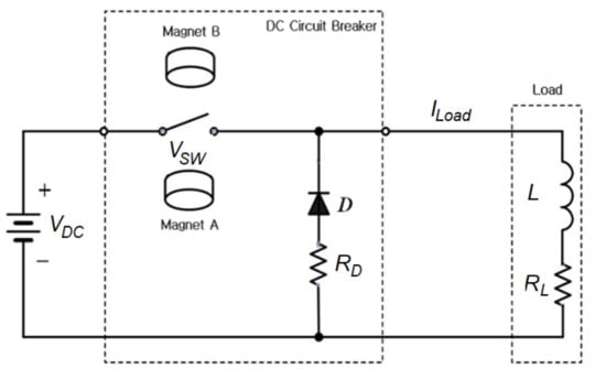
Figure 1.
Arc extinguishing concept of the proposed DC switch.
In addition, in order to suppress the generation of continuous arc voltage caused by inductive loads, freewheeling technology is used to dissipate arc energy through a branch of a diode and dump resistor. Without freewheeling diode branch, the voltage between the switch contacts can be calculated as Equation (1).
In Equation (1) the second term is normally a negative value and the magnitude of it increases much larger than the supply voltage, , during shutting off of the switch, so that the transient voltage between the switch contact during switching off increases very much and is related to the load inductance, L. However, a freewheeling diode branch limits the voltage between the switch contacts as Equation (2).
The DC switch automatic testing device shown in Figure 2 allows the breaking pole to be open at various speeds by the stepping motor and the gear drive, and it can automatically perform repeated cut-off tests to analyze the durability of the electric contacts. Tests were performed at air-conditioned room temperature. The testing device automatically turns on and off iteratively and measures Ohmic resistance between the contacts every 500 operating cycles.
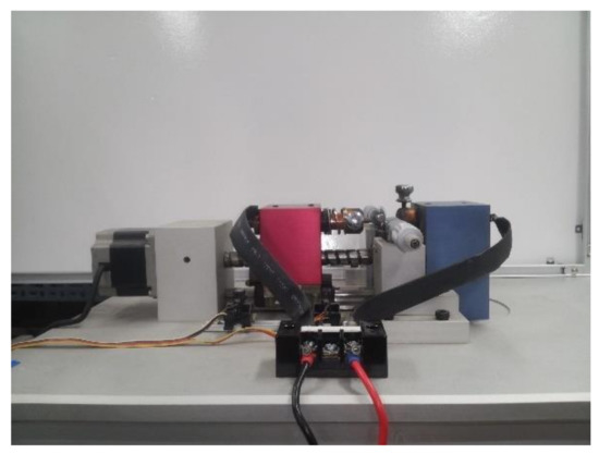
Figure 2.
Photo of DC switch automatic test device.
The contact life is related with the contact material because the erosion of the contact or the movement of the contact mass depends on the contact material [14]. In this study, aging characteristics of the electric contacts according to various contact materials of the DC switch were tested. Five composite metal contact materials of the DC switch, tungsten-copper (AW18-Cu), silver-palladum (AgPd), silver-tungsten (AgW), silver-nickel-copprer (AgNi-Cu), silver-tin-copper (AgSnO2-Cu), in addition to pure copper (Cu) as summarized in Table 1, were tested. Here, 5 samples were provided by braze welding the 5 composite metal clads bonded on a copper bulk to get high thermal conductivity and low resistance. The composite metal layer had a thickness of around 1 mm, and the length of the copper bulk was around 30 mm long. In the case of the pure copper contact, only the copper bulk was used.

Table 1.
Five kinds of contact materials of the DC switch experiment.
Figure 3 shows the photo of the five electrode samples for the electric contacts tested in this study.
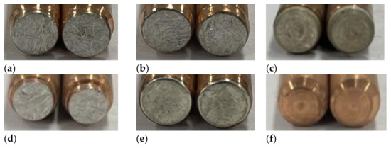
Figure 3.
Photo of five kinds of samples for the electric contacts tested in this study; (a) AW18-Cu, (b) AgPd, (c) AgW, (d) AgNi-Cu, (e) AgSnO2-Cu, (f) Pure Cu.
In this study, in order to perform the aging test according to the material type of the electric contacts, the repeated open/close test conditions were set as shown in Table 2. This paper compares the contact life characteristics for an inductive load with a supply voltage of 400 V, a load current of 5 or 10 A and a load time constant of 20 ms. The DC switch is tested by being turned on for about 1.5 s and then turned off for 2 s, 13,000 times; the performance of the electrode is continuously evaluating by calculating the voltage drop between the electric contacts and the corresponding resistance value when conducting, every 500 cycles.
Table 2.
Contact electrode aging test conditions.
3. Experimental Results
3.1. 400 V/5 A Load Condition
In the experiment, the conduction time of the DC switch electrode under test was approximately 1.5 s and the cut-off time was approximately 2 s. Figure 4 shows voltage/current waveforms between electrode contacts of DC switch according to electrode materials under 400 V/5 A load/current conditions during the conduction period. Because two samples of pure copper (Cu) and silver tungsten (AgW) failed to match the IEC 60898-3 standard, Figure 4 shows the waveforms for only the other four sample cases. All four test samples conformed to the IEC 60898-3 standard, since the voltage drop between the contacts was under 300 mV.
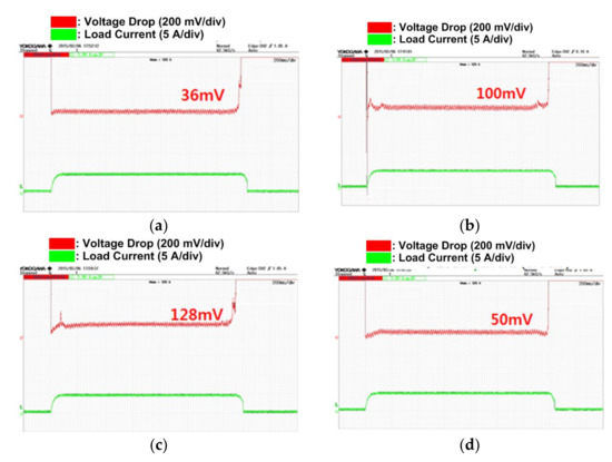
Figure 4.
Example of voltage/current waveforms between electrode contacts according to electrode material for 400 V/5 A experimental conditions (time: 200 ms/Div); (a) AgNi-Cu, (b) AgSnO2-Cu, (c) AW18-Cu, and (d) AgPd.
Table 3 shows the magnitude of the voltage drop between electrode contacts according to the electrode material measured every 500 cycles when the DC switch was repeatedly turned on/off under 400 V/5 A load conditions. In the case of pure copper (Cu) and silver-tungsten (AgW), the voltage drop between electrode contacts increased sharply to 922 [mV] and 633 mV, respectively, after 1000 operating cycles, which was not in accordance with IEC60898-3 standards. Moreover, these two kinds of electrodes were severely burned out after 1000 ON/OFF cycles, thus no more experiments were possible. Therefore, in this study, pure copper (Cu) and silver-tungsten (AgW) were no longer considered as target contact materials.
Table 3.
Voltage drop between switch contacts under 400 V/5 A load conditions.
The voltage drop between the contacts of the remaining 4 electrode materials under test was initially less than 20 mV, but it can be seen that it varied depending on the material within the range of up to under 400 mV during the 13,000 repetitive operations. Considering that the voltage drop between the contacts of the electrode is the degree of aging of the electrode, it is noticed that the aging characteristics of the four contact materials are similar until 3000 repetitions, but after 3000 repetitions, the life characteristics vary depending on the contact material.
This phenomenon is evident when looking at the trend of the voltage drop of the contact point according to the electrode material in Figure 5 as a whole. In other words, the magnitude of the voltage drop of the contact point, according to the four electrode materials that initially showed a low voltage drop of 8~20 mV, uniformly increases with a similar pattern as the repetitive operation progresses up to 3000 times. Then, in the repeated operation periods from 3000 to 11,000 cycles, the voltage drop size of the contact point, according to the four electrode materials, has various distributions, ranging from 28 mV to 400 mV. However, after 11,500 repeated operations, the deviation decreases to within 10% (voltage value less than 100 mV), and the contact performance recovers again.
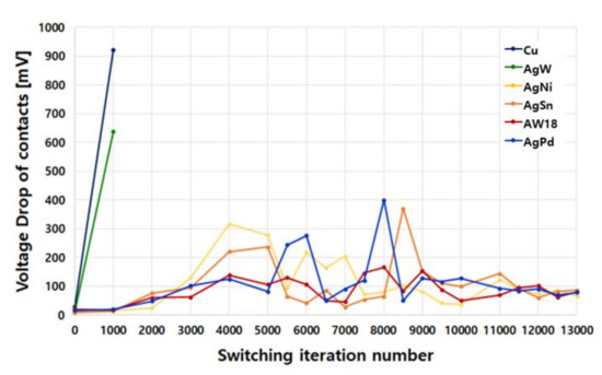
Figure 5.
Voltage drop of electrode contact according to electrode material under 400 V/5 A load conditions.
3.2. 400 V/10 A Load Condition
Table 4 shows the magnitude of the voltage drop between electrode contacts according to the electrode material measured every 500 cycles when the DC switch is repeatedly turned on/off under 400 V/10 A load current conditions.
Table 4.
Voltage drop between switch contacts under 400 V/10 A load conditions.
Figure 6 shows the variation in the performance of the four electrode contacts according to the electrode material under the 10 A load current condition. It can be seen that the voltage between the electrode contacts in the conduction condition is measured in a variety of ranges from 30 mV to 506 mV, depending on the composition of the electrode material.
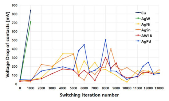
Figure 6.
Voltage drop of electrode contact according to electrode material under 400 V/10 A load conditions.
In the 10 A load current condition of Figure 6, when looking at the trend of the voltage drop of the contact according to the electrode material as a whole, life characteristics slightly differ from the 5 A load current condition. That is, the voltage drop value for each electrode material during the initial operation was in the range of 8 mV to 20 mV under the 5 A load current condition, but it becomes 2.5 to 4 times greater under the 10 A load current condition as 30 mV to 50 mV. In addition, the magnitude of the voltage drop of the contact point according to the four electrode materials shows a greater deviation from 24 mV to 506 mV in the repeated operation periods of up to 11,000 cycles. This means that the maximum voltage drop between electrode contacts is increased by about 20% compared to the 400 V/5 A load current conditions.
As with the 5 A load current condition, after 11,500 times of the repeated operation, the mutual deviation decreases to within 30% (within 10% in the case of a 5 A load current), the voltage drop decreases to 170 mV or less (within 100 mV in the case of a 5 A load current), and the contact performance is restored again. Excluding the AgPd electrode materials with relatively poor contact characteristics, after 11,500 repetitive operations, the mutual deviation decreases to within 12% and the voltage drop decreases to 150 mV or less.
3.3. Aging Characteristics of Electrode Contacts
Analyzing the whole aging test results of the contacts of the low-voltage DC switch, the voltage drop of all the electrode materials increases uniformly up to the initial 4000 on/off cycles, and shows a zig-zagged pattern from 4000 on/off cycles to approximately 9000 on/off cycles, and then decreases again after 9000 on/off cycles. This means that the contact points of the DC switches initially deteriorate and then recover from a certain point of on/off cycles.
The characteristics of AW18-Cu contact material and AgNi-Cu contact material are explicitly different. In the initial repetitive operation up to about 7500 times, the AW18-Cu contact material shows the best performance. However, from about 7500 to about 10,000 operations, the performance of the AgNi-Cu contact material is temporarily excellent, and after about 10,500 operations, the performance of the AW18-Cu contact material becomes the best again.
AgSnO2-Cu contact materials do not have superior performance compared to other contact materials in the initial and late characteristics of repeated operation under all load current conditions. Ag-Pd contact material shows excellent properties in both 400 V/5 A and 400 V/10 A load conditions up to the initial 5000 times. Therefore, it is evaluated as the most suitable contact material for applications requiring repeated operation of 5000 times or less.
Figure 7 shows the state of contact surfaces according to electrode material during repeated operation (10,000 times) under the 10 A load current condition. AgW and pure copper contact materials are burnt due to severe carbonization of both the (+) and (−) electrodes, whereas the other contact materials are not severely burnt at the (+) and (−) electrode.
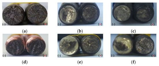
Figure 7.
Contact surface condition of each electrode material in repeated operation 10,000 under 10 A load current condition; (a) AgW (failed after 1000 operations), (b) AgNi-Cu, (c) AgSnO2-Cu, (d) Cu (failed after 1000 operations), (e) AgPd, and (f) AW18-Cu.
Figure 8 shows the contact surface condition of electrodes according to the electrode material after 10,000 repeated operations and 13,000 repeated operations for the four contact electrode materials of AgNi-Cu, AgSnO2-Cu, AgPd, and AW18-Cu under the 10 A load current condition. In the figure, the photo on the left shows the contact surface status after 10,000 repeated operations, and the photo on the right shows the contact surface status after 13,000 repeated operations. In the case of all four electrode materials, it can be seen that the contact state of the (−) pole became cleaner after 13,000 repeated operations. This can be said to prove the characteristic of the contact recovery after 10,000 repeated operations.
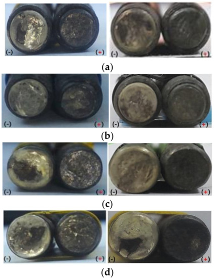
Figure 8.
Comparison of deterioration of each electrode material in repeated operations, 10,000 (left photo) and 13,000 (right photo), under the 10 A load current condition, (a) AgNi-Cu, (b) AgSnO2-Cu, (c) AgPd, and (d) AW18-Cu.
4. Conclusions
This paper evaluated six kinds of contact materials for the application of low-voltage DC (LVDC) switches. Generally, the states of all the contact surface rapidly deteriorated during the repeated operation period up to about 4000 operations, but remained at those levels until 10,000 repeated operations; after 10,000 operations, the states of all the contact surfaces were improved again, showing a recovery phenomenon.
According to the load current condition, the voltage drop between electrodes converged with a different voltage level during 13,000 repetitive operations. In other words, the voltage drop of the electrodes operating under 400 V/5 A load conditions converged to 80 mV, while the voltage drop of the electrode operating under 400 V/10 A load conditions converged to 140 mV, which is almost doubled.
Except AgW and pure copper, the other four composite materials passed the IEC 60898-3 standard. The contact state of AgNi-Cu composite material was good until 3500 operation cycles, the AgNi-Cu composite material was good until 5000 operation cycles, and the AgPd composite material was good until 5500 operation cycles. AW18-Cu composite material showed the most stable and excellent contact performance for LVDC switches during the entire test operation period of 13,000 cycles.
Funding
This work was supported in part by Basic Science Research Program through the National Research Foundation of Korea (NRF) funded by the Ministry of Education (Grants No. 2016R1D1A3B01008279). This work is also partly supported by Kongju National University.
Conflicts of Interest
The author declares no conflict of interest.
References
- Xiao, D.; AlAshery, M.K.; Qiao, W. Optimal price-maker trading strategy of a wind power producer using virtual bidding. J. Mod. Power Syst. Clean Energy 2021, 1–13. [Google Scholar] [CrossRef]
- Xiao, D.; Qiao, W.; Qu, L. Risk-averse offer strategy of a photovoltaic solar power plant with virtual bidding in electricity markets. In Proceedings of the 10th IEEE Conference on Innovative Smart Grid Technology (ISGT 2019), Washington, DC, USA, 17–20 February 2019; pp. 1–5. [Google Scholar] [CrossRef]
- Pratt, A.; Kumar, P.; Aldridge, T.V. Evaluation of 400V DC distribution in telco and data centers to improve energy efficiency. In Proceedings of the INTELEC 07-29th International Telecommunications Energy Conference, Rome, Italy, 30 September–4 October 2007; pp. 32–39. [Google Scholar] [CrossRef]
- Babasaki, T. Developing of Higher Voltage Direct-Current Power-feeding Prototype System. In Proceedings of the Intelec 2010, Orlando, FL, USA, 6–10 June 2010; pp. 1–5. [Google Scholar] [CrossRef]
- Rodriguez-Diaz, E.; Vasquez, J.C.; Guerrero, J.M. Guerrero, Intelligent DC homes in future sustainable energy systems: When efficiency and intelligence work together. IEEE Consum. Mag. 2016, 5, 74–80. [Google Scholar] [CrossRef]
- Dragicevic, T.; Vasquez, J.C.; Guerrero, J.M.; Skrlec, D. Advanced LVDC electrical power architectures and microgrids: A step toward a new generation of power distribution networks. IEEE Electrif. Mag. 2014, 2, 54–65. [Google Scholar] [CrossRef]
- Jahromi, M.G.; Mirzaeva, G.; Mitchell, S.D.; Gay, D. Powering mobile mining machines: DC versus AC power. IEEE Ind. Appl. Mag. 2016, 22, 63–72. [Google Scholar] [CrossRef]
- Kim, H. DC distribution systems and circuit breaking technology. KIPE Mag. Korean Inst. Power Electron. 2010, 15, 40–46. [Google Scholar]
- Yuba, T.; Baek, S.; Kiryu, K.; Nakamura, A.; Miyazawa, H.; Noritake, M.; Hirose, K. Development of plug and socket -outlet for 400 volts direct current distribution system. In Proceedings of the 8th International Conference on Power Electronics—ECCE Asia, Jeju, Korea, 30 May–3 June 2011; pp. 218–222. [Google Scholar] [CrossRef]
- Lee, S.-M.; Kim, H.-S. Development of DC Circuit Breaker using Magnet Arc Extinguisher. Trans. Korean Inst. Power Electron. 2012, 17, 21–26. [Google Scholar] [CrossRef][Green Version]
- ABB Circuit-Breakers for Direct Current Applications; ABB Group Co.: Bergamo, Italy, 2007; pp. 1–56.
- Safety Concepts and Circuit Protection for LVDC Grids in Datacenters and in Telecommunications. In Proceedings of the 2018 IEEE International Telecommunications Energy Conference (INTELEC), Turino, Italy, 7–11 October 2018.
- Ou, C.; Nakayama, R.; Zen, S.; Takeuchi, N.; Yasuoka, K. Influence of Arc Discharge on Contact Erosion and Contact Resistance in a Hybrid DC Switch. In Proceedings of the 2018 IEEE Holm Conference on Electrical Contacts, Albuquerque, NM, USA, 14–18 October 2018. [Google Scholar] [CrossRef]
- Meng, F.; Lu, J.; Lu, N.; Zhu, Y.; Chen, Z.; Huang, Q. Mass material transfer of Ag-SnO2 contact material in DC level. In Proceedings of the 52nd IEEE Holm Conference on Electrical Contacts, Montreal, QC, Canada, 25–27 September 2006. [Google Scholar] [CrossRef]
- Ren, W.; Wang, H.; Chang, C.; Xue, S.; Chen, Y. Experimental investigation and understanding of the intermittent molten bridge phenomena and mechanism of contacts with super low opening speed. IEEE Trans. Comp. Pack. Manu. Tech. 2016, 6, 418–423. [Google Scholar] [CrossRef]
- Witter, G.J.; Chen, Z.K.; Anderson, C. The effect of electrode temperature and heat capacity on the electrical erosion and material transfer for DC switching of electrical contacts. In Proceedings of the 2014 IEEE 60th Holm Conference on Electrical Contacts (Holm), New Orleans, LA, USA, 12–15 October 2014. [Google Scholar] [CrossRef]
- Chen, Z.K.; Witter, G.J. A correlation of silver tin indium oxide-copper composite rivet interface bond quality and switching endurance life in DC relays. In Proceedings of the 26th International Conference on Electrical Contacts (ICEC 2012), Beijing, China, 14–17 May 2012; pp. 174–179. [Google Scholar] [CrossRef]
- Chen, M.; Yamada, Y.; Zen, S.; Takeuchi, N.; Yasuoka, K. ON-State Contact Resistance and Arc-Less Commutation Characteristics of Cu-W Clad Contact Materials in a Hybrid DC Switch. IEEE Trans. Compon. Packag. Manuf. Technol. 2020, 10, 1138–1147. [Google Scholar] [CrossRef]
- Standard IEC 60898-3: Electrical accessories—Circuit-breakers for d.c. operation having a rated DC voltage not exceeding 440V, a rated current not exceeding 125 A and a rated short-circuit capacity not exceeding 10,000 A. Available online: https://webstore.iec.ch/publication/27206 (accessed on 5 October 2021).
- Kim, Y.; Kim, H. Novel DC Circuit Breaker using Magnet-Extinguisher and Free-Wheel Diode. J. Electr. Eng. Technol. 2019, 14, 497–503. [Google Scholar] [CrossRef]


Publisher’s Note: MDPI stays neutral with regard to jurisdictional claims in published maps and institutional affiliations. |
© 2021 by the author. Licensee MDPI, Basel, Switzerland. This article is an open access article distributed under the terms and conditions of the Creative Commons Attribution (CC BY) license (https://creativecommons.org/licenses/by/4.0/).