Article

Magnetic Coupler Optimization for Inductive Power Transfer System of Unmanned Aerial Vehicles

School of Engineering and Built Environment, Griffith University, Nathan, QLD 4111, Australia
*
Author to whom correspondence should be addressed.
Energies 2021, 14(21), 7024; https://doi.org/10.3390/en14217024
Submission received: 28 September 2021 / Revised: 11 October 2021 / Accepted: 19 October 2021 / Published: 27 October 2021

Abstract

:
Unmanned aerial vehicles (UAVs) have been widely used in military and civilian applications. However, the insufficient cruising range restricts the development of UAVs due to the limitation of their battery. Inductive power transfer (IPT) is an effective way to charge the battery and solve this problem. Magnetic coupler is a key component of the IPT system, which greatly affects the power transfer and efficiency of the IPT. This paper proposes a new magnetic coupler with vertical spiral coils and ferrite PQI cores for the IPT system of UAVs, which can enhance the magnetic coupling and improve the performance of the IPT system. Finite element simulations are used to investigate the magnetic field distribution and coupling capability of the proposed magnetic coupler. In addition, an experimental platform is built to prove the validity of the IPT system using the proposed magnetic coupler. The results show that the coupling coefficient can reach 0.98, and the system transfer efficiency is 89.27% with an output power of 93 W. The IPT system also has a perfect misalignment tolerance and can achieve a stable output power.

1. Introduction

In past decades, unmanned aerial vehicles (UAVs) with different capabilities have been widely used in many applications, such as water sampling [1], oil and gas surveys [2], powerline inspection [3], coastline patrol, disaster relief [4,5,6], agriculture [7], and logistics [8,9,10]. Currently, the propulsion systems of the UAVs can be divided into three types, including traditional internal combustion engines (ICEs), hybrid electric propulsion systems (HEPSs), and pure electric motors (EMs). The UAVs with ICEs have a long cruising range. However, they will increase fuel consumption and lead to air pollution. In addition, thermal efficiency is the main drawback of ICEs, which ranges at 40% [11]. HEPS is the combination of the ICE and EM, which has high propulsion efficiency and can reduce fuel consumption. This kind of propulsion system allows large aircraft and increases cruising ranges. The research of the HEPS for the UAVs has been carried out by many researchers. Paper [12] used the series and parallel HEFS for the design process of the fixed-wing UAVs, and it shows that HEPS consumes less energy than traditional aircraft in certain tasks. In [13], a brushless DC motor design solution being used in the hybrid drive for a UAV was presented, and the overall efficiency of the system was 87.3% at the speed of 8000 rpm. However, the HEPS for the UAVs need energy management to balance the working of the ICE and EM, and the above two types of UAVs are normally large and heavy.
The UAVs using pure EMs are widely used in civilian applications, such as the consumer UAVs, which are usually small and easy to operate. Moreover, they do not consume fuels and are environmentally friendly. However, the insufficient endurance capability limits the development of UAVs using pure electricity due to the lack of battery capacity. Inductive power transfer (IPT) can be used for UAV wireless charging to solve the issue effectively. Compared with the current charging method for UAVs with plug-in AC or DC chargers, IPT can prevent mechanical wear and an electric spark and reduce manual operation. The UAVs can be charged in an outdoor environment, even in extreme rain and snow weather conditions. They can also acquire automatically distributed charging without having to return to the operator by establishing multiple distributed charging stations.
As an important component of the IPT system, magnetic couplers have been studied in many research projects for the IPT of UAVs. The high coupling coefficient of a magnetic coupler is the key factor to transfer substantial power and improve efficiency. Paper [14] presents a frustum structure, with ferrite I cores and a transmitting coil arranged on the inside of the frustum and a receiving coil without a magnetic core attached to the UAV; the maximum coupling coefficient is approximately 0.52. Paper [15] proposes a novel orthogonal magnetic coupler, which has a polarized transmitter with a flat U-type core and a perpendicular air-cored receiving coil. The coupling coefficient is 0.3. Paper [16] uses a face-to-face magnetic coupler. The transmitting coil is made of a double-layer coil and two circular coils connected in series. The receiving coil is a circular coil, which is installed on the UAV’s body; the maximum coupling coefficient is 0.174. Similarly, in [17], the primary coil has two spiral coils, which are connected in series. The secondary coil adopts a disc coil structure without a magnetic core, and the maximum coupling coefficient is 0.27. In [18], a novel cross-type magnetic coupler is proposed for UAV wireless charging. The receiving coils are made of two opposite-direction series coils that are installed on the two landing gears of the UAV. The transmitting coils are made of three series of coils that are wound in the same direction. This magnetic coupler can reduce the leakage inductance, converge the magnetic flux lines, and improve the magnetic coupling performance. The maximum coupling coefficient can reach 0.328. Nevertheless, the coupling coefficients of these magnetic couplers are inadequate. When the displacement between the receiving and transmitting sides is large, the magnetic coupling deteriorates. For instance, the power transfer efficiency is low and cannot maintain a stable power transfer.
In this paper, an effective IPT system with vertical spiral coils and ferrite PQI cores is proposed to charge the battery of a UAV wirelessly. The magnetic coupler can achieve tight coupling when the receiving coil is inserted into the transmitting coil due to the small air gap. The main contributions are summarized as follows:
(1)
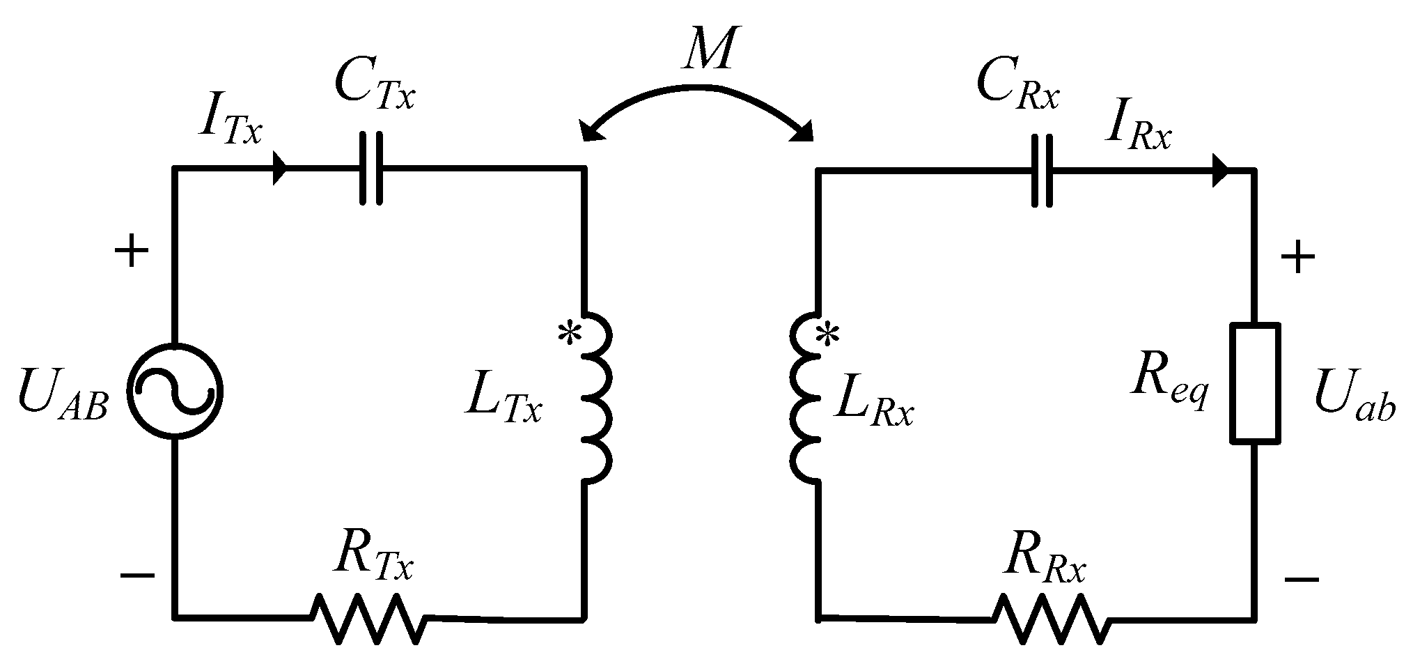
The IPT system is proposed. The parameters such as power, efficiency, coupling coefficient, and compensation capacitances are analyzed by building an equivalent model.
(2)
The design principle of the magnetic coupler for UAVs is pointed out in detail. Three types of magnetic couplers are analyzed and compared. An optimized magnetic coupler with ferrite PQI cores is obtained. This magnetic coupler can provide a strong magnetic flux density, achieve a high coupling coefficient, and maintain a stable power transfer. The magnetic field distribution and coupling capability are analyzed using the finite element software COMSOL.
(3)
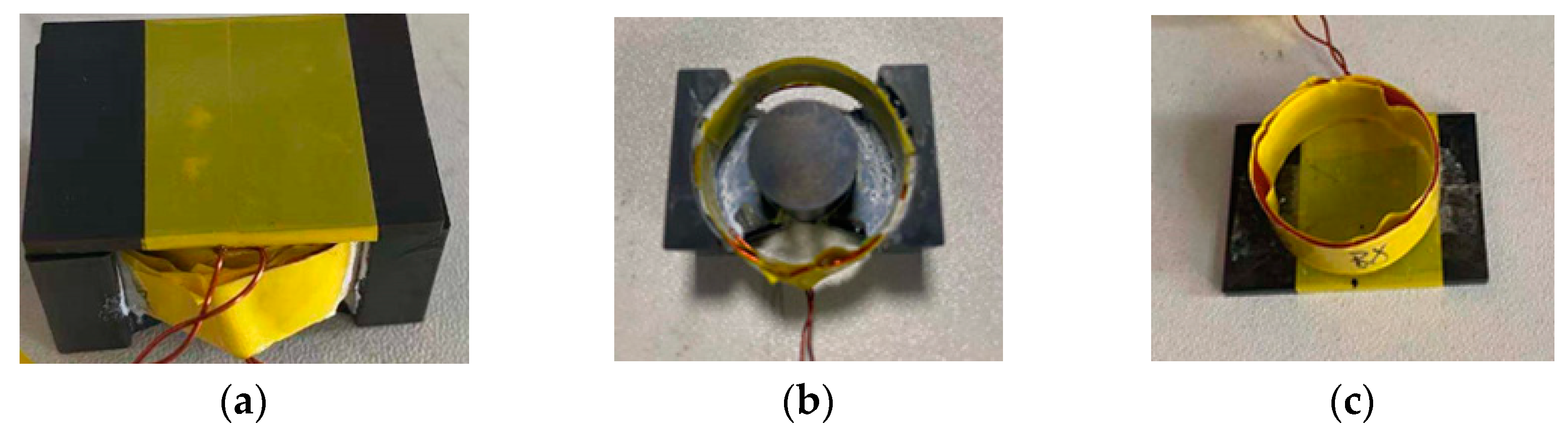
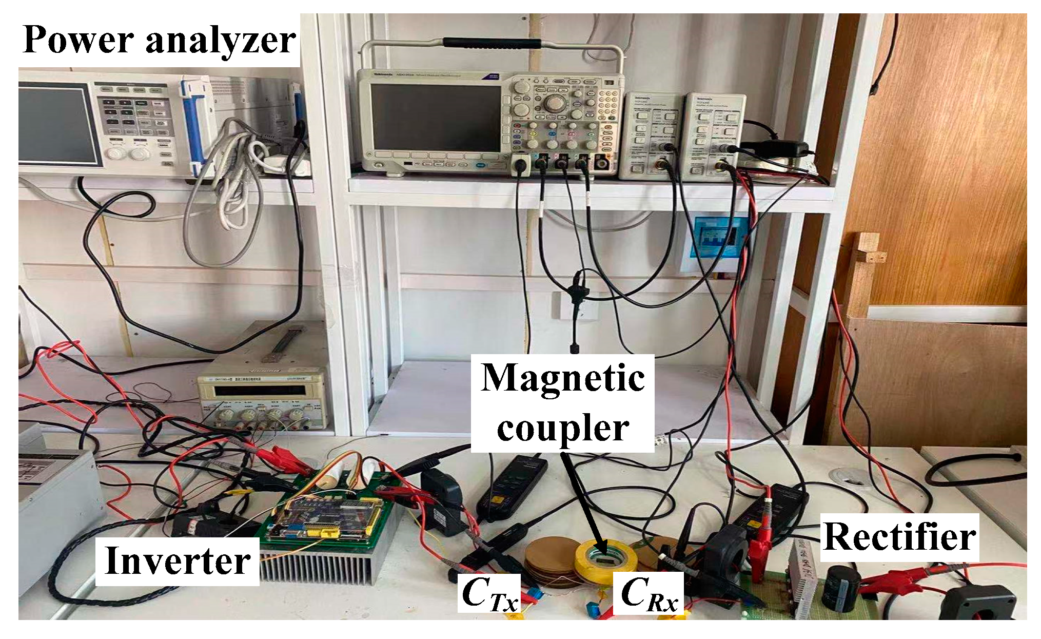
An experimental platform is implemented to investigate the coupling capability of the magnetic coupler and the IPT system power transfer, which verifies the validity of the proposed IPT system for UAVs.
This paper is arranged as follows. Section 1 introduces the research background and an overview of the whole work. In Section 2, an IPT system is built and modeled. In Section 3, the optimization for the magnetic coupler of the IPT system is carried out by comparing three types of magnetic couplers and simulation. In Section 4, a testing platform is built to verify the performance of the IPT system. Finally, in Section 5, the discussion summarizes all the work and points out future work.

2. IPT System for UAVs

This paper focuses on the optimization of the magnetic coupler, Thus, a typical and common circuit for the IPT system is selected, as shown in Figure 1. A high-frequency sinusoidal voltage is generated by the full-bridge inverter (four SiC MOSFETs, S1S4), and the high-frequency alternating magnetic field generated by the transmitting coil (TX coil) can transfer the power to the receiving coil (RX coil). Then, the AC voltage is converted into a DC voltage by using the full-bridge rectifier circuit (four Schottky diodes, D1D4). Two compensation circuits are used on the transmitting and receiving sides to compensate for leakage inductance, eliminate reactive power, and achieve maximum power transfer. The four basic compensation circuits are series–series (SS), series-parallel (SP), parallel–parallel (PP), and parallel–series (PS) [19,20,21]. Some complex compensation circuits, such as inductance–capacitance–inductance (LCL) and double-sided inductance–capacitance–inductance (LCC) also exist [22]. In this paper, SS compensation is used for the IPT system because it can achieve a constant output current, and the circuit is simple and light for UAVs.
In Figure 1, Uin and Iin are the input DC voltage and current for the inverter. LTx and LRx are self-inductances of the transmitting and receiving coils, respectively. CTx and CRx are the compensation capacitors for the transmitting and receiving coils, respectively. M is the mutual inductance between the transmitting and receiving coils. CO is the filter capacitor, and RL is the load. Uout and Iout are the DC voltage and current of the load.
The IPT system transfer efficiency η from the DC source to the load can be calculated as follows:
η = P o u t P i n = U o u t I o u t U i n I i n
where Pin is the input power of the DC source, and Pout is the output power of the load.
The coupling coefficient k can be calculated as:
k = M L T x L R x .
UAB and Uab are the voltages of the transmitting- and receiving-side compensation circuits, and Req is the equivalent load resistance before the rectifier. The voltage and current of the compensation network are under the continuous conduction mode (CCM) operation in the steady state, only considering the fundamental frequency components [23]. They can be expressed as follows [24]:
U A B = 2 2 π U i n ,   U a b = π 2 2 U o u t ,   R e q = 8 π 2 R L .
Figure 2 shows the equivalent circuit of the IPT system with SS compensation circuits. RTx and RRx are the series equivalent resistances of the transmitting and receiving coils. ITx and IRx are the currents of the transmitting and receiving coils. On the receiving side, the impedance ZRx can be calculated as [25]
Z R x = j ω L R x + 1 j ω C R x + R R x + R e q
where ω is the resonant frequency of the receiving side.
From [25], the reflected impedance Zr from the receiving side to the transmitting side is as follows:
Z r = j ω M I R x I T x = ω 2 M 2 Z R x .
The reflected resistance and reactance of the reflected impedance Zr can be written as follows [26]:
{ Re ( Z r ) = ω 4 M 2 ( R e q + R R x ) ( ω 2 L R x 1 C R x ) 2 + ω 2 ( R e q + R R x ) 2 Im ( Z r ) = ω 3 M 2 ( ω 2 L R x 1 C R x ) ( ω 2 L R x 1 C R x ) 2 + ω 2 ( R e q + R R x ) 2 .
Typically, to eliminate reactive power and achieve the maximum power transfer, the reflected reactance Im(Zr) should be zero, which means
ω 2 L R x 1 C R x = 0 .
The resonant compensation capacitor CRx of the receiving coil can be expressed as follows:
C R x = 1 ω 2 L R x .
The total system input impedance Zin can be expressed as follows [26]:
Z i n = Z T x + Z r = j ω L T x + 1 j ω C T x + R T x + Z r .
The total input reactance should be zero to achieve maximum output power and transfer efficiency, that is,
Im ( Z T x ) = 0 .
The resonant compensation capacitor CTx of the transmitting coil can be expressed as
C T x = 1 ω 2 L T x .
The resonant frequency ω is typically the same as the switching frequency ω0 of the full-bridge inverter to ensure that the IPT system can achieve the maximum transfer power and efficiency.

3. Magnetic Coupler Optimization for UAVs

3.1. Magnetic Coupler Design Principle

The magnetic coupler is the key component that affects the transmission power and efficiency of the IPT system. The following aspects should be considered when designing the magnetic coupler for UAV wireless charging.
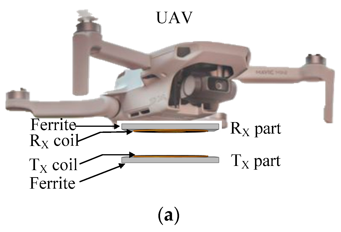
  • The space occupied by the receiving part should be considered. The receiving part is installed on the UAV, such that the receiving part should be compact and light to avoid the impact of overweight and imbalance on the flight status of the UAV.
  • The magnetic coupler should have a strong magnetic flux density and a high coupling coefficient to improve the transfer power and efficiency of the IPT system.
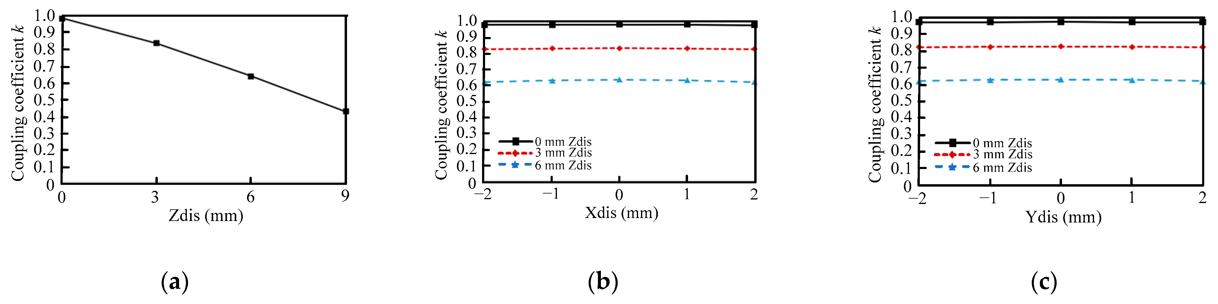
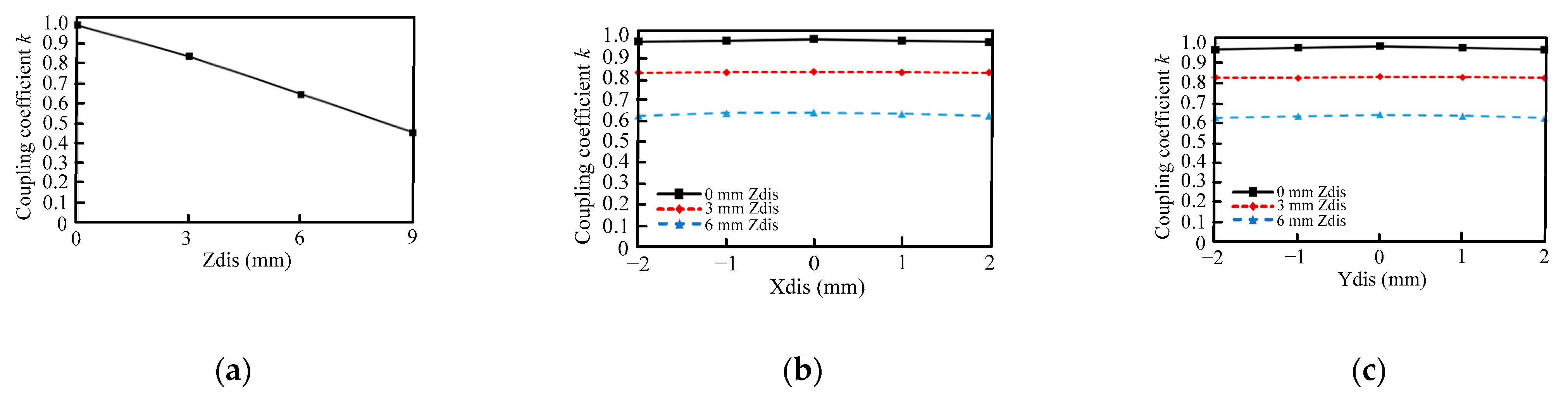
  • The magnetic coupler should have enhanced misalignment tolerance. The UAV cannot ensure that it works in complete alignment every time due to the limitation of its landing accuracy. Thus, enhanced misalignment tolerance can ensure that the IPT system transfers a stable power and is efficient.
  • The leakage flux density should meet the International Commission on Non-Ionizing Radiation Protection safety standard. The leakage magnetic field will heat the metal parts of the UAV, which will affect the UAV’s work and even damage it. From the safety standard [27], the minimum flux density that harms humans is 2.7 × 10⁻⁵ T, such that the goal in this paper is to ensure that the leakage flux density for the UAV is less than this safety standard.

3.2. Typical Magnetic Coupler with Circular Coils and I Cores

Currently, the magnetic coupler using circular coils is one of the common structures for IPT systems [28,29,30]. The circular coils can achieve high transfer efficiency when the air gap is small and the transmitting and receiving coils are coaxial. However, when the air gap or misalignment is large, the coupling coefficient becomes small, which decreases the transfer power and efficiency. To compare and prove the superiority of the proposed magnetic coupler in this paper, a typical magnetic coupler using circular coils and I cores is investigated, as shown in Figure 3. The magnetic field distribution and coupling coefficient are investigated to verify whether this kind of structure is suitable for a UAV IPT system.
As shown in Figure 3, the transmitting part (TX part) and the receiving part (RX part) are the same, in which both are made of a circular coil and an I core. The receiving part is installed on the abdomen of the UAV. The transmitting part is normally installed in a charging station. For this kind of small UAV, the allowed space for the receiving coil is 40 mm × 35 mm without affecting the sensors working. Considering that the receiving coil allowed space and minimizing the influence of the receiving coil weight on UAVs’ flight, the outer and inner diameters of the transmitting and receiving coils are 25 and 11 mm, respectively, and the turns of the coils are 15. Zdis, Xdis, and Ydis are the displacements of the Z-, X-, and Y-axis directions, respectively.
Three-dimensional simulations are used to investigate the magnetic field of the magnetic coupler on the basis of COMSOL. The transmitting coil is excited with 1 A, 100 kHz. Figure 4 shows the magnetic field distribution of the typical magnetic coupler with circular coils and I cores. The magnetic flux is mainly converged between the I cores, and the magnetic field is symmetrically distributed along the X- and Y-axis directions. The peak flux densities of the magnetic coupler in the XZ and YZ planes are 0.02 and 0.01 T, respectively. The maximum leakage flux densities for the UAV in the XZ and YZ planes are denoted as “A” and “A’” which are 4.468 × 10⁻⁴ and 8.558 × 10⁻⁴ T, respectively. They are higher than 2.7 × 10⁻⁵ T and, consequently, do not satisfy the safety standard.
The variation in coupling coefficient k of the typical magnetic coupler with displacement is shown in Figure 5. In Figure 5a, with the increase in Z-axis displacement, the coupling coefficient is reduced. The maximum and minimum coupling coefficients are 0.945 and 0.25, respectively. Figure 5b,c show the variation in coupling coefficient with the X- and Y-axis displacements under different Z-axis displacements, respectively. The maximum variations of the coupling coefficient are 0.0546 and 0.0506, respectively. These results show that when the Z-axis displacement is large, the magnetic coupling worsens, and the later misalignment (X- and Y-axis displacements) tolerance is terrible. In consideration of the leakage flux density and magnetic coupling capability, the typical magnetic coupler with circular coils and I cores is unsuitable for the IPT system of UAVs.

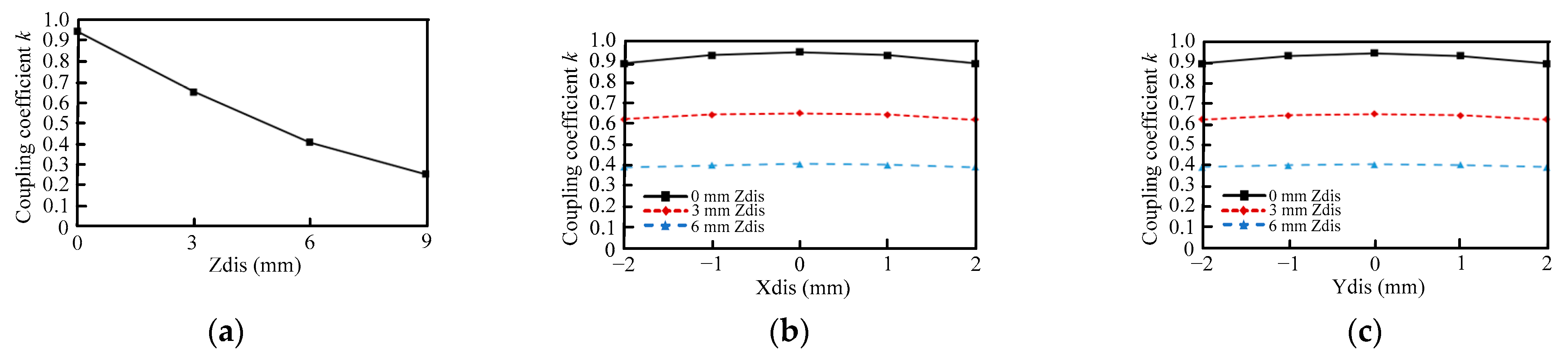
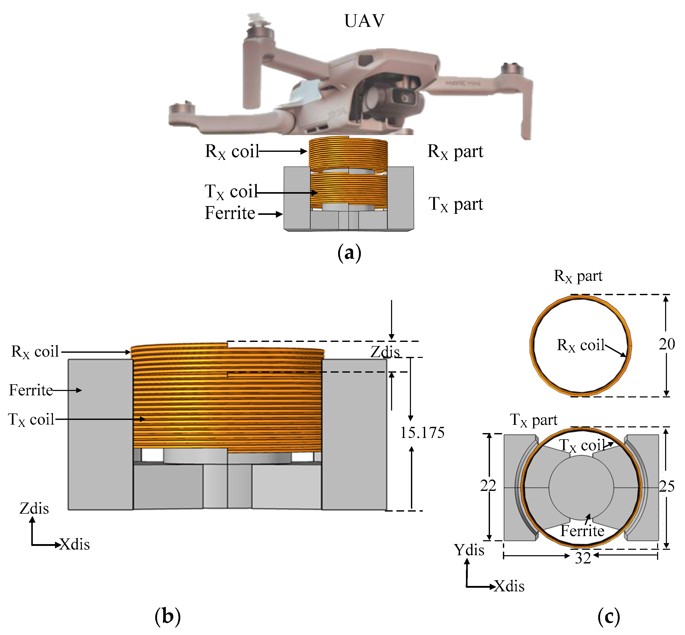
3.3. Proposed Magnetic Coupler with Vertical Spiral Coils and a PQ Core

As mentioned above, the typical magnetic coupler has the problems of weak magnetic coupling and high misalignment sensitivity when the displacement is changed. To solve these problems, a new magnetic coupler using vertical spiral coils and a PQ ferrite core is proposed for the IPT system of UAVs, as shown in Figure 6. To compare the performance of the proposed magnetic coupler with that of the typical magnetic coupler (Figure 3), the turns, outer diameter, and specification of the coils are the same as the parameters of the typical magnetic coupler. From Figure 6b, the receiving part is made of a vertical spiral coil attached to the abdomen of the UAV. To reduce the influence of the receiving part on the UAV’s flight, no ferrite exists on the receiving part. The transmitting part is made of a vertical spiral coil and a PQ ferrite core. Using vertical spiral coils can effectively increase the magnetic coupling area and reduce the air gap between the transmitting and receiving coils. Meanwhile, the structure of the PQ core will constrain the flux lines in the magnetic coupler and transfer considerable magnetic flux to the receiving coil. Thus, the proposed magnetic coupler with vertical spiral coils and a PQ ferrite core can effectively reduce leakage inductance and improve magnetic coupling.
Figure 7 shows the magnetic field distribution of the proposed magnetic coupler with vertical spiral coils and a PQ core. The magnetic field is symmetrically distributed along the X- and Y-axis directions, and most of the magnetic flux is concentrated around the magnetic coupler. The peak flux densities of the magnetic coupler in the XZ and YZ planes are 0.02 and 0.00842 T, respectively. “B” and “B’” represent the maximum leakage flux densities for the UAV in the XZ and YZ planes, which are 3.246 × 10⁻³ and 3.578 × 10⁻³ T, respectively. They are higher than 2.7 × 10⁻⁵ T, thereby failing to meet the safety standard. Hence, a reduction of leakage flux density must be considered to meet the safety standard.
The variation in coupling coefficient k of the magnetic coupler with vertical spiral coils and a PQ core with displacement is shown in Figure 8. The coupling coefficient decreases with the increase in Z-axis displacement. The maximum and minimum coupling coefficients are 0.865 and 0.398, respectively. They are lower and higher than the coupling coefficient of the typical magnetic coupler (in Figure 5a), which means that the misalignment sensitivity of the magnetic coupler with vertical spiral coils and a PQ core is lower than that of the typical magnetic coupler. As shown in Figure 8b,c, the maximum variations of the coupling coefficient along the X- and Y-axis displacements are 0.01 and 0.0136, respectively. They are smaller than those of the typical magnetic coupler (in Figure 5b,c). The coupling coefficient is stable in the lateral displacement.
In sum, the magnetic coupler with vertical spiral coils and a PQ core has the following characteristics: (1) the magnetic field is symmetrically distributed along the X- and Y-axis directions; (2) the coupling coefficient is higher than that of the typical magnetic coupler when the Z-axis displacement is large; (3) the misalignment sensitivity is lower than that of the typical magnetic coupler, especially it has a perfect lateral displacement tolerance.

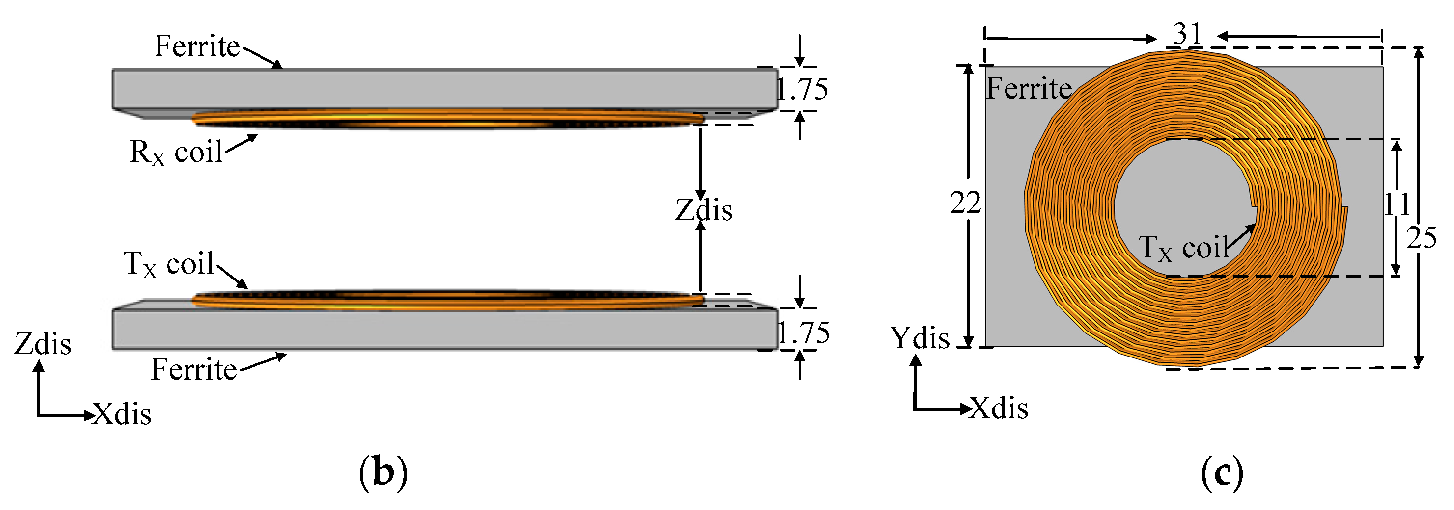
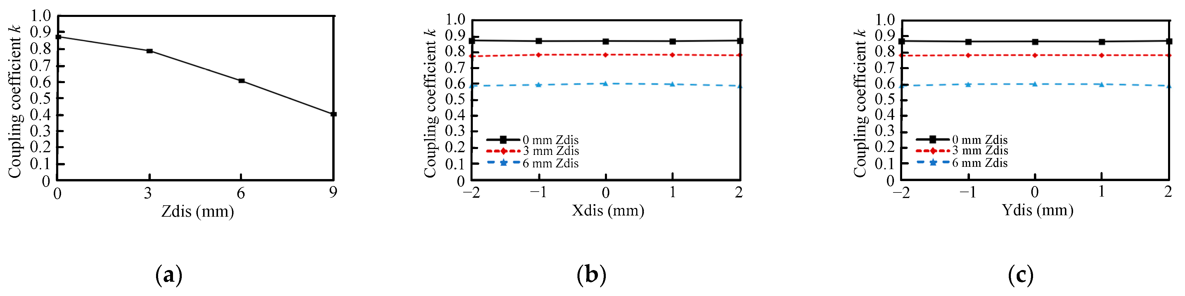
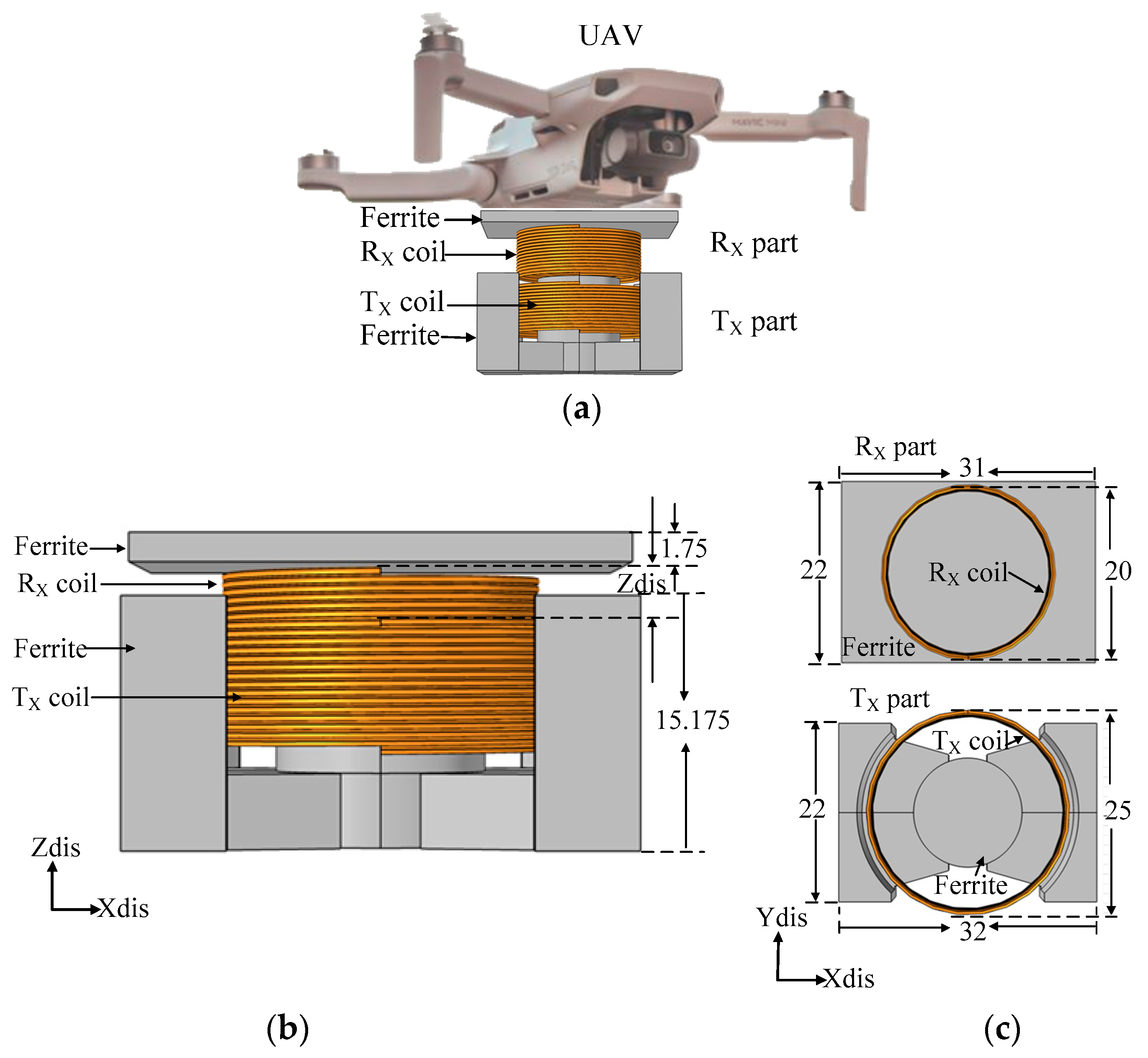
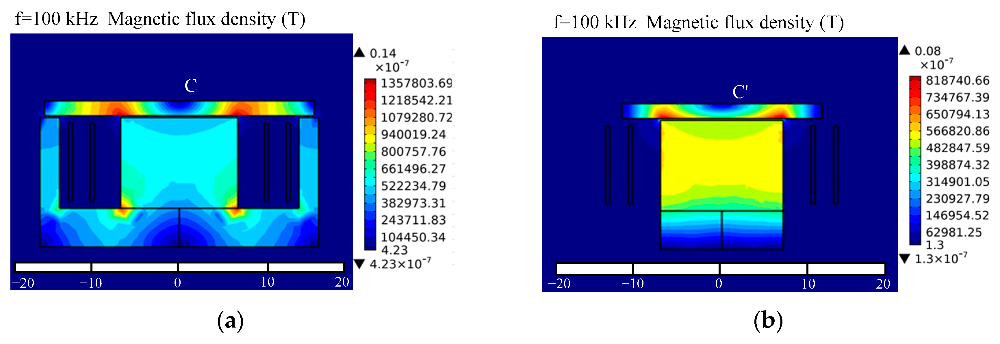
3.4. Proposed Magnetic Coupler with Vertical Spiral Coils and PQI Cores

From the above analysis, the typical magnetic coupler and the proposed magnetic coupler with vertical spiral coils and a PQ core have the problems of weak magnetic coupling, large leakage flux density, and high misalignment sensitivity. Both are unsuitable for the IPT system of UAVs. Therefore, a new magnetic coupler with vertical spiral coils and PQI ferrite cores is proposed to solve these drawbacks, as shown in Figure 9. An I ferrite core is added to the receiving coil, which can enhance the magnetic coupling and reduce the leakage magnetic flux density. The I core is thin and light, which almost does not affect the UAV’s flight status.
Figure 10 shows the magnetic field distribution of the proposed magnetic coupler with vertical spiral coils and PQI cores. The magnetic field is symmetrically distributed along the X- and Y-axis directions. The magnetic flux is converged in the magnetic coupler. The peak flux densities of the magnetic coupler in the XZ and YZ planes are 0.14 and 0.08 T, respectively. The maximum leakage flux densities for the UAV in the XZ and YZ planes are denoted as “C” and “C′”, which are 4.231 × 10⁻⁷ and 1.299 × 10⁻⁷ T, respectively. They are less than 2.7 × 10⁻⁵ T, conforming to the safety standard.
Figure 11 shows the variation in coupling coefficient k of the magnetic coupler with vertical spiral coils and PQI cores with displacement. The maximum and minimum coupling coefficients are 0.978 and 0.423, respectively. They are higher than those of the typical magnetic coupler and the magnetic coupler with a PQ core (in Figure 5a and Figure 8a). Figure 11b,c show the variation in coupling coefficient with the X- and Y-axis displacements under different Z-axis displacements, respectively. The maximum variations of the coupling coefficient are 0.01 and 0.015. These results prove that this kind of magnetic coupler has a high coupling coefficient and a perfect lateral displacement tolerance.
Therefore, the magnetic coupler with vertical spiral coils and PQI cores is selected for the IPT system of the UAV in this paper due to the following merits:
(1)
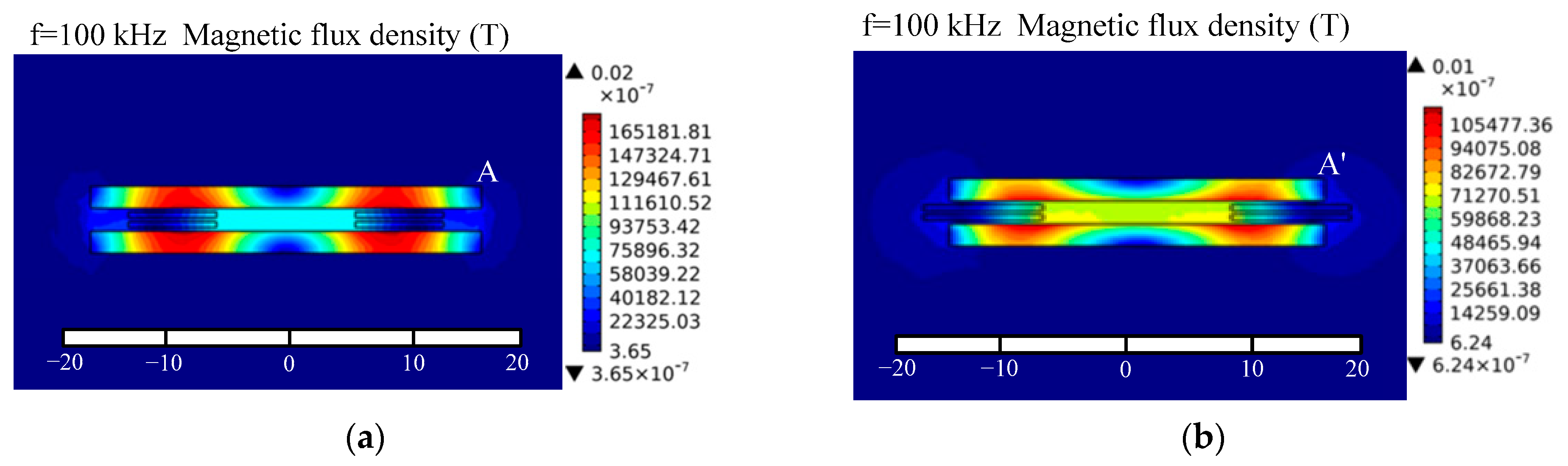
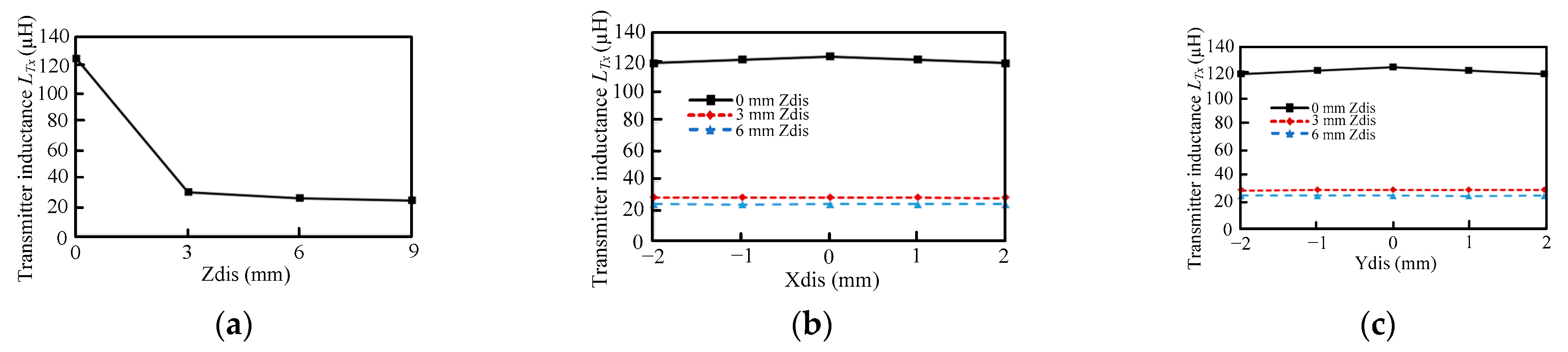
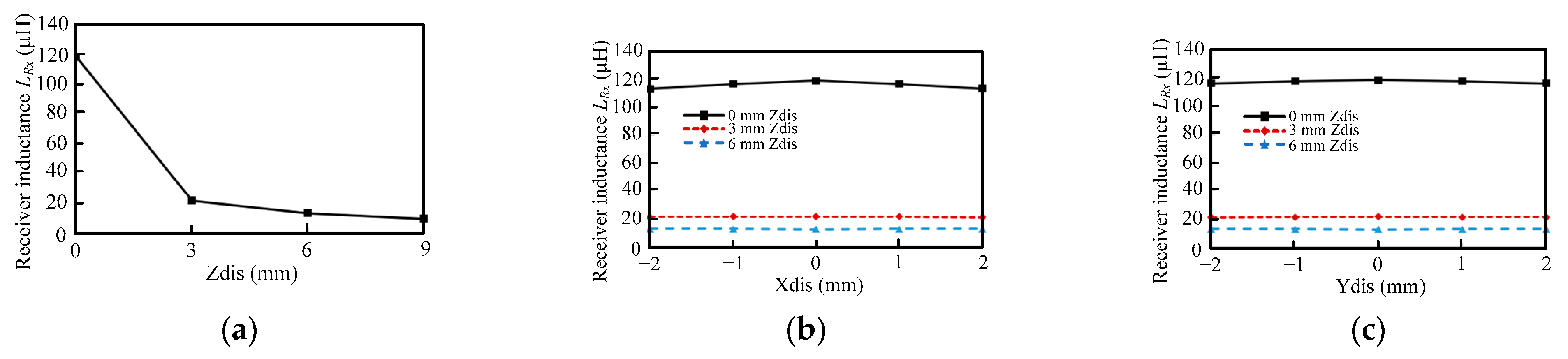
The magnetic field is symmetrically distributed along the X- and Y-axis directions. It has a perfect lateral misalignment tolerance, which is valuable to provide a stable power transfer.
(2)
It has high magnetic flux density and coupling coefficient.
(3)
The leakage flux density is less than the safety standard, which will not affect the work of the UAV.

4. Experimental Testing

4.1. Magnetic Coupler Testing

An experimental prototype is constructed to investigate the performance of the proposed magnetic coupler with vertical spiral coils and PQI cores, as shown in Figure 12. The ferrite PQ and I cores with a permeability of 3300 are from TDK Corporation. The I core plate is made of two 15.5 mm × 22 mm × 1.75 mm I cores, and it is only approximately 4 g, which has a minimal impact on the UAV’s flight. The parameters of the magnetic coupler are listed in Table 1. An LCR meter (HIOKI IM 3536) is used to measure the self-inductance and coupling coefficient variation with displacement. This LCR meter has high accuracy with 0.05% rdg, which ensures the accuracy of measurement.
Figure 13 shows the measured coupling coefficient k variation with displacement. From Figure 13a, with the increase in Z-axis displacement, the coupling coefficient ranges from 0.984 to 0.446. Figure 13b,c show the variation in coupling coefficient with X- and Y-axis displacements. The maximum variations of k are 0.011 and 0.016. The coupling coefficient is stable within the lateral displacement.
The variation in self-inductance LTx of the transmitting coil with displacement is shown in Figure 14. With an increased Z-axis displacement, the self-inductance LTx is reduced. From Figure 14b,c, the maximum variations of LTx are 4.276 and 5.186 µH in the X- and Y-axis displacements, respectively.
Figure 15 shows the variation in self-inductance LRx of the receiving coil with displacement. The self-inductance LRx is reduced with an increased Z-axis displacement, as shown in Figure 14a. The variation in self-inductance LRx with X- and Y-axis displacements is shown in Figure 15b,c. The maximum variations of LRx are 5.559 and 2.229 µH.

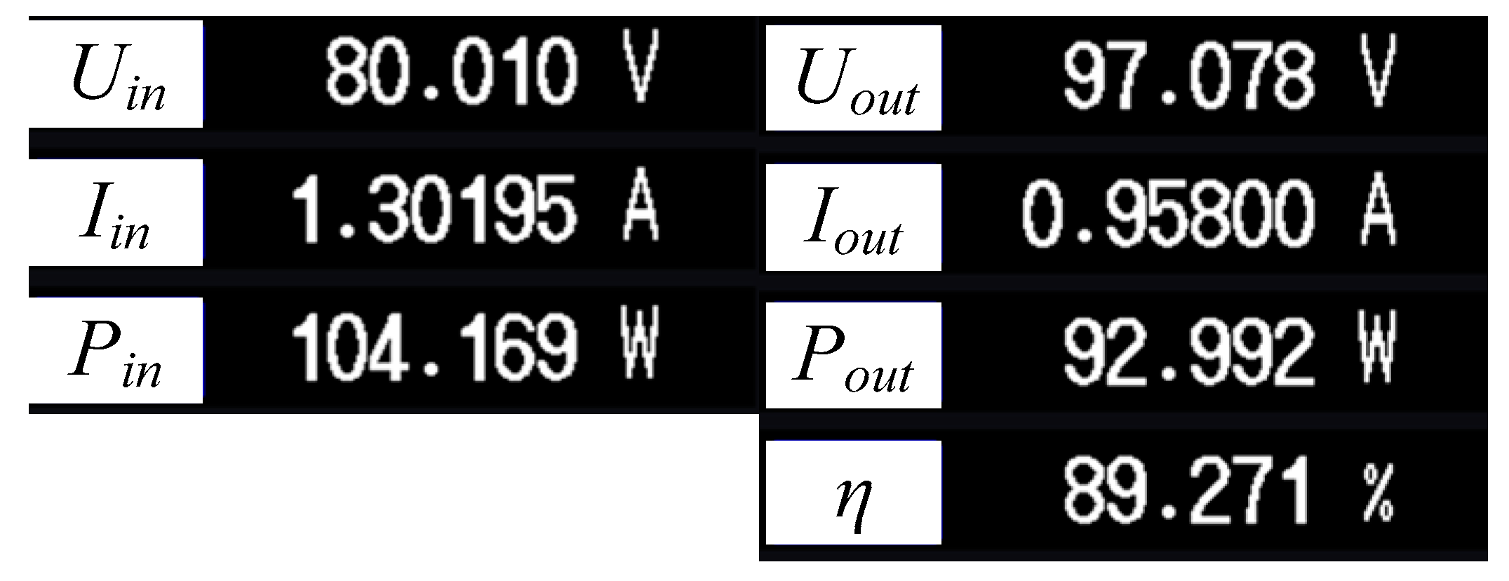
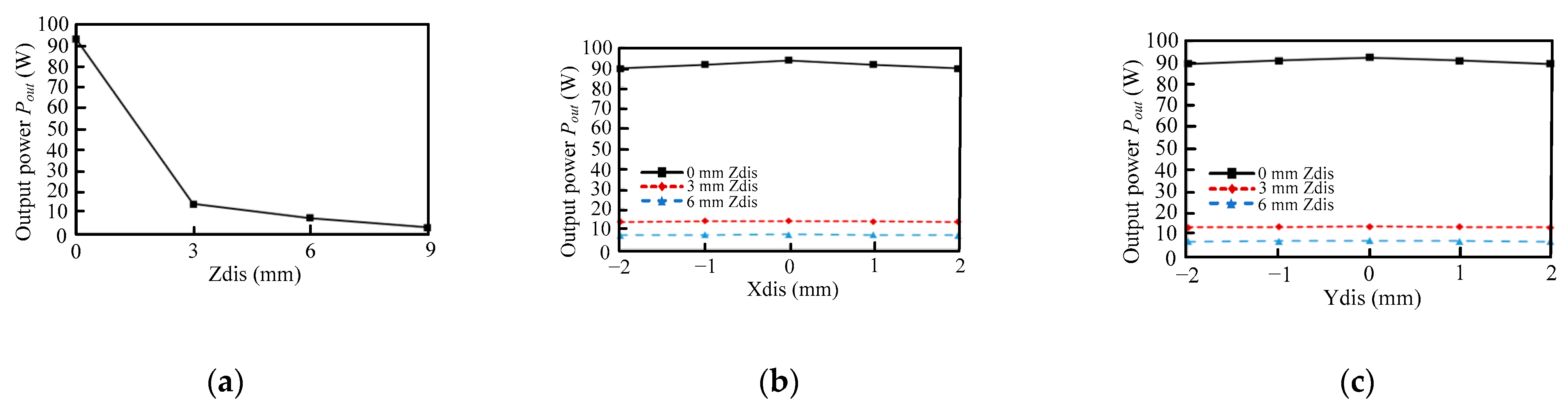
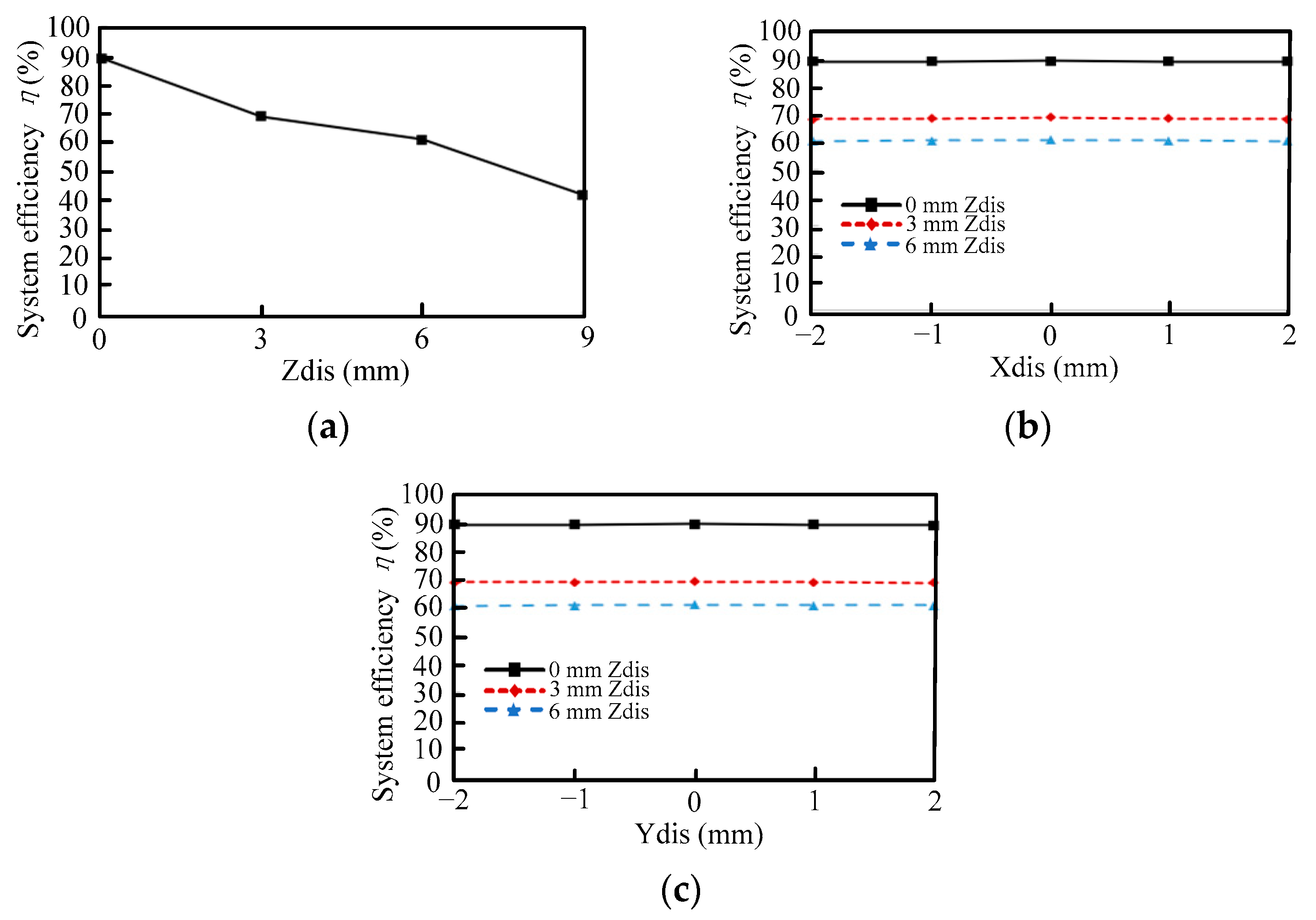
4.2. Power Transfer Testing

A test platform is built to investigate the performance of the IPT system using the proposed magnetic coupler with vertical spiral coils and PQI cores, as shown in Figure 16. It consists of a high-frequency inverter, two compensation capacitors, the proposed magnetic coupler, and a full-bridge rectifier circuit. An electric load (Chroma 63123A) is used as the load. A power analyzer (HIOKI PW6001) is used to measure the power and efficiency of the IPT system. The experimental parameters of the IPT system are listed in Table 2.
Figure 17 shows the power and efficiency testing under complete alignment. The output power for the load is 92.99 W, and the system efficiency can reach 89.27%.
Figure 18 shows the output power Pout variation with displacement. In Figure 18a, the output power decreases with an increased Z-axis displacement. As shown in Figure 18b,c, when the X- and Y-axis displacements change from −2 to 2 mm at zero Z-axis displacement, the power Pout variation ranges are 89.071–92.992 W and 90.083–92.992 W, respectively. The output power is relatively stable.
Figure 19 shows the system efficiency η variation with displacement. As shown in Figure 19a, when the Z-axis displacement ranges from 0 to 9 mm, the efficiency η is from 89.271% to 42.091%. From Figure 19b,c, when the X- and Y-axis displacements are from −2 to 2 mm, the maximum variations in system efficiency η are 0.43% and 0.29%, respectively. The system transfer efficiency is stable. These results prove that the IPT system has a perfect lateral displacement tolerance and can achieve a stable power transfer.

5. Discussion

In this paper, a novel effective IPT system using a magnetic coupler with vertical spiral coils and PQI ferrite cores was proposed for UAV wireless charging. The following work has been finished.
First, the IPT system modeling was implemented to obtain compensation capacitors.
Second, one typical magnetic coupler with circular coils and I cores, one proposed magnetic coupler with vertical spiral coils and a PQ core, and another magnetic coupler with vertical spiral coils and PQI cores were investigated and compared. Their magnetic coupler capabilities, such as magnetic field distribution and coupling coefficient, were studied using the finite element software COMSOL.
The simulation results show that the magnetic coupler with vertical spiral coils and PQI cores has the following advantages: (1) strong magnetic flux density and high coupling coefficient; (2) enhanced lateral misalignment tolerance; (3) the magnetic field is symmetrically distributed along the X- and Y-axis directions; and (4) the leakage flux density conforms to the safety standard.
Lastly, an experimental platform was built to validate the proposed IPT system. The test results show that the IPT system can achieve high-efficiency stable power transfer. The IPT system can transfer 92.99 W with a system efficiency of 89.271%.
This kind of magnetic coupler is also suitable for wireless charging systems in which the receiving part has a planar structure such as electric vehicles, cleaning robots, automatic guided vehicles, and rotary transformers. High-permeability magnetic materials, such as amorphous and nanocrystalline ones, could be considered in future work to improve the performance of the IPT system.

Author Contributions

Conceptualization, X.L. and J.L.; methodology, X.L.; software, X.L.; validation, X.L., J.L. and S.S.; formal analysis, X.L.; investigation, X.L.; resources, J.L.; data curation, X.L.; writing—original draft preparation, X.L.; writing—review and editing, X.L.; visualization, X.L.; supervision, J.L.; project administration, X.L.; funding acquisition, J.L. All authors have read and agreed to the published version of the manuscript.

Funding

This research received no external funding.

Conflicts of Interest

The authors declare no conflict of interest.

References

  1. Agarwal, P.; Singh, M.K. A multipurpose drone for water sampling & video surveillance. In Proceedings of the 2019 Second International Conference on Advanced Computational and Communication Paradigms (ICACCP), Gangtok, India, 25–28 February 2019; pp. 1–5. [Google Scholar]
  2. Cho, J.; Lim, G.; Biobaku, T.; Kim, S.; Parsaei, H. Safety and security management with unmanned aerial vehicle (UAV) in oil and gas industry. Procedia Manuf. 2015, 3, 1343–1349. [Google Scholar] [CrossRef] [Green Version]
  3. Vemula, S.; Frye, M. Mask R-CNN powerline detector: A deep learning approach with applications to a UAV. In Proceedings of the 2020 AIAA/IEEE 39th Digital Avionics Systems Conference (DASC), San Antonio, TX, USA, 11–15 October 2020; pp. 1–6. [Google Scholar]
  4. Gharibi, M.; Boutaba, R.; Waslander, S.L. Internet of drones. IEEE Access 2016, 4, 1148–1162. [Google Scholar] [CrossRef]
  5. Aljehani, M.; Inoue, M. Performance evaluation of multi-UAV system in post-disaster application: Validated by HITL simulator. IEEE Access 2019, 7, 64386–64400. [Google Scholar] [CrossRef]
  6. Lu, M.; Bagheri, M.; James, A.P.; Phung, T. Wireless charging techniques for UAVs: A review, reconceptualization, and extension. IEEE Access 2018, 6, 29865–29884. [Google Scholar] [CrossRef]
  7. Oliveira, H.C.; Guizilini, V.C.; Nunes, I.P.; Souza, J.R. Failure detection in row crops from UAV images using morphological operators. IEEE Geosci. Remote Sens. Lett. 2018, 15, 991–995. [Google Scholar] [CrossRef]
  8. Sawadsitang, S.; Niyato, D.; Tan, P.; Wang, P. Joint ground and aerial package delivery services: A stochastic optimization approach. IEEE Trans. Intell. Transp. Syst. 2019, 20, 2241–2254. [Google Scholar] [CrossRef] [Green Version]
  9. Perreault, M.; Behdinan, K. Delivery drone driving cycle. IEEE Trans. Veh. Technol. 2021, 70, 1146–1156. [Google Scholar] [CrossRef]
  10. Wang, D.; Hu, P.; Du, J.; Zhou, P.; Deng, T.; Hu, M. Routing and scheduling for hybrid truck-drone collaborative parcel delivery with independent and truck-carried drones. IEEE Internet Things J. 2019, 6, 10483–10495. [Google Scholar] [CrossRef]
  11. Suti, A.; Rito, G.D.; Galatolo, R. Climbing performance enhancement of small fixed-wing UAVs via hybrid electric propulsion. In Proceedings of the 2021 IEEE Workshop on Electrical Machines Design, Control and Diagnosis (WEMDCD), Modena, Italy, 8–9 April 2021; pp. 305–310. [Google Scholar]
  12. Finger, D.F.; Bil, C.; Braun, C. Initial sizing methodology for hybrid electric general aviation aircraft. J. Aircr. 2020, 57, 245–255. [Google Scholar] [CrossRef]
  13. Bogusz, P.; Korkosz, M.; Powrózek, A.; Prokop, J.; Wygonik, P. An analysis of properties of the BLDC motor for unmanned aerial vehicle hybrid drive. In Proceedings of the 2015 International Conference on Electrical Drives and Power Electronics (EDPE), Tatranska Lomnica, Slovakia, 21–23 September 2015; pp. 458–464. [Google Scholar]
  14. Obayashi, S.; Kanekiyo, Y.; Nishizawa, K.; Kusada, H. 85-kHz band 450-W inductive power transfer for unmanned aerial vehicle wireless charging port. In Proceedings of the 2019 IEEE Wireless Power Transfer Conference (WPTC), London, UK, 8–21 June 2019; pp. 80–84. [Google Scholar]
  15. Cai, C.; Wu, S.; Jiang, L.; Zhang, Z.; Yang, S. A 500-W wireless charging system with lightweight pick-up for unmanned aerial vehicles. IEEE Trans. Power Electron. 2020, 35, 7721–7724. [Google Scholar] [CrossRef]
  16. Zhang, H.; Chen, Y.; Jo, C.-H.; Park, S.-J.; Kim, D.-H. DC-link and switched capacitor control for varying coupling conditions in inductive power transfer system for unmanned aerial vehicles. IEEE Trans. Power Electron. 2021, 36, 5108–5120. [Google Scholar] [CrossRef]
  17. Song, Y.; Sun, X.; Wang, H.; Dong, W.; Ji, Y. Design of charging coil for unmanned aerial vehicle-enabled wireless power transfer. In Proceedings of the 2018 8th International Conference on Power and Energy Systems (ICPES), Colombo, Sri Lanka, 21–22 December 2018; pp. 268–272. [Google Scholar]
  18. Cai, C.; Liu, J.; Wu, S.; Zhang, Y.; Jiang, L.; Zhang, Z.; Yu, J. Development of a cross-type magnetic coupler for unmanned aerial vehicle IPT charging systems. IEEE Access 2020, 8, 67974–67989. [Google Scholar] [CrossRef]
  19. Zhang, Y.; Chen, K.; He, F.; Zhao, Z.; Lu, T.; Yuan, L. Closed-form oriented modeling and analysis of wireless power transfer system with constant-voltage source and load. IEEE Trans. Power Electron. 2016, 31, 3472–3481. [Google Scholar] [CrossRef]
  20. Zhang, W.; Wong, S.; Tse, C.K.; Chen, Q. Analysis and comparison of secondary series- and parallel-compensated inductive power transfer systems operating for optimal efficiency and load-independent voltage-transfer ratio. IEEE Trans. Power Electron. 2014, 29, 2979–2990. [Google Scholar] [CrossRef]
  21. Liu, N.; Habetler, T.G. Design of a universal inductive charger for multiple electric vehicle models. IEEE Trans. Power Electron. 2015, 30, 6378–6390. [Google Scholar] [CrossRef]
  22. Li, S.; Li, W.; Deng, J.; Nguyen, T.D.; Mi, C.C. A double-sided LCC compensation network and its tuning method for wireless power transfer. IEEE Trans. Veh. Technol. 2015, 64, 2261–2273. [Google Scholar] [CrossRef]
  23. Choi, B.G.; Sohn, Y.-H.; Lee, E.S.; Han, S.H.; Kim, H.R.; Rim, C.T. Coreless transmitting coils with conductive magnetic shield for wide range ubiquitous IPT. IEEE Trans. Power Electron. 2019, 34, 2539–2552. [Google Scholar] [CrossRef]
  24. Lee, E.S.; Choi, B.G.; Kim, M.Y.; Han, S.H. Optimal number of turns design of the IPT coils for laptop wireless charging. IEEE Access 2021, 9, 19548–19561. [Google Scholar] [CrossRef]
  25. Jiang, C.; Chau, K.T.; Liu, C.; Lee, C.H. An overview of resonant circuits for wireless power transfer. Energies 2017, 10, 894. [Google Scholar] [CrossRef]
  26. Liu, C.; Jiang, C.; Song, J.; Chau, K.T. An effective sandwiched wireless power transfer system for charging implantable cardiac pacemaker. IEEE Trans. Ind. Electron. 2019, 66, 4108–4117. [Google Scholar] [CrossRef]
  27. ICNIRP. Guidelines for limiting exposure to time-varying electric and magnetic fields (1 Hz to 100 kHz). Health Phys. 2010, 99, 818–836. [Google Scholar] [CrossRef] [PubMed]
  28. Budhia, M.; Covic, G.A.; Boys, J.T. Design and optimization of circular magnetic structures for lumped inductive power transfer systems. IEEE Trans. Power Electron. 2011, 26, 3096–3108. [Google Scholar] [CrossRef]
  29. Abiezer, T.; Carretero, C.; Boys, J.T.; Covic, G.A. Ferrite-less circular pad with controlled flux cancelation for EV wireless charging. IEEE Trans. Power Electron. 2017, 32, 8349–8359. [Google Scholar]
  30. Nayak, P.; Kishan, D.; Annaiah, P. Investigation of MI between circular spiral coils with misalignments for EV battery charging. IET Sci. Meas. Technol. 2018, 12, 844–850. [Google Scholar] [CrossRef]
Figure 1. Circuit diagram of IPT system. * represtents the polarity of the coils, which is commonly used in the transformer.
Energies 14 07024 g001
Figure 2. Equivalent circuit of IPT system with SS compensation circuits. * represtents the polarity of the coils, which is commonly used in the transformer.
Energies 14 07024 g002
Figure 3. Typical magnetic coupler with circular coils and I cores (unit: mm): (a) installation diagram of the magnetic coupler; (b) front view; (c) top view of the transmitting part.
Energies 14 07024 g003aEnergies 14 07024 g003b
Figure 4. Magnetic field distribution of the typical magnetic coupler: (a) XZ plane; (b) YZ plane.
Energies 14 07024 g004
Figure 5. Variation in coupling coefficient of the typical magnetic coupler variation with displacement: (a) Z-axis; (b) X-axis; (c) Y-axis.
Energies 14 07024 g005
Figure 6. Magnetic coupler with vertical spiral coils and a PQ core: (a) installation diagram of the magnetic coupler; (b) front view; (c) top view.
Energies 14 07024 g006
Figure 7. Magnetic field distribution of the magnetic coupler with vertical spiral coils and a PQ core: (a) XZ plane; (b) YZ plane.
Energies 14 07024 g007
Figure 8. Variation in coupling coefficient of the magnetic coupler with vertical spiral coils and a PQ core with displacement: (a) Z-axis; (b) X-axis; (c) Y-axis.
Energies 14 07024 g008
Figure 9. Magnetic coupler with vertical spiral coils and PQI cores: (a) installation diagram of the magnetic coupler; (b) front view; (c) top view.
Energies 14 07024 g009
Figure 10. Magnetic field distribution of the magnetic coupler with vertical spiral coils and PQI cores: (a) XZ plane; (b) YZ plane.
Energies 14 07024 g010
Figure 11. Variation in coupling coefficient of the magnetic coupler with vertical spiral coils and PQI cores with displacement: (a) Z-axis; (b) X-axis; (c) Y-axis.
Energies 14 07024 g011
Figure 12. Prototype of the magnetic coupler with vertical spiral coils and PQI cores: (a) whole magnetic coupler; (b) transmitting part; (c) receiving part.
Energies 14 07024 g012
Figure 13. Measured coupling coefficient variation with displacement: (a) Z-axis; (b) X-axis; (c) Y-axis.
Energies 14 07024 g013
Figure 14. Measured transmitter’s self-inductance variation with displacement: (a) Z-axis; (b) X-axis; (c) Y-axis.
Energies 14 07024 g014
Figure 15. Measured receiver’s self-inductance variation with displacement: (a) Z-axis; (b) X-axis; (c) Y-axis.
Energies 14 07024 g015
Figure 16. Test platform for the IPT system.
Energies 14 07024 g016
Figure 17. Power and efficiency testing of the IPT system under complete alignment.
Energies 14 07024 g017
Figure 18. Measured output power variation with displacement: (a) Z-axis; (b) X-axis; (c) Y-axis.
Energies 14 07024 g018
Figure 19. Measured system efficiency variation with displacement: (a) Z-axis; (b) X-axis; (c) Y-axis.
Energies 14 07024 g019
Table 1. Parameters of the proposed magnetic coupler with vertical spiral coils and PQI cores.
ParameterValue
Turns of transmitting and receiving coils15
Diameter of transmitting coil25 mm
Diameter of receiving coil20 mm
Diameter of the single-turn coil0.5 mm
Cross-section of single-turn coil0.2 mm2
Size of PQ core (L × W × H)32 × 22 × 15.175 mm
Size of I core plate (L × W × H)31 × 22 × 1.75 mm
Permeability of ferrite core3300
Table 2. Parameters of the IPT system.
SymbolParameterValue
UinInput DC voltage80 V
fSystem working frequency100 kHz
LTxInductance of transmitting coil123.98 µH
LRxInductance of receiving coil118.47 µH
CTxCompensation capacitance of transmitter20.57 nF
CRxCompensation capacitance of receiver21.38 nF
RTxResistance of transmitting coil0.201 Ω
RRxResistance of receiving coil0.165 Ω
MMutual inductance119.24 µH
kCoupling coefficient0.984
RLResistance of load100 Ω
Publisher’s Note: MDPI stays neutral with regard to jurisdictional claims in published maps and institutional affiliations.

