Article

Study on the Positioning Accuracy of GNSS/INS Systems Supported by DGPS and RTK Receivers for Hydrographic Surveys

1
Department of Geodesy, Gdańsk University of Technology, Gabriela Narutowicza 11-12, 80-233 Gdańsk, Poland
2
Department of Geodesy and Oceanography, Gdynia Maritime University, Morska 81-87, 81-225 Gdynia, Poland
3
Department of Transport and Logistics, Gdynia Maritime University, Morska 81-87, 81-225 Gdynia, Poland
4
Marine Technology Ltd., Wiktora Roszczynialskiego 4-6, 81-521 Gdynia, Poland
5
Faculty of Maritime Studies, University of Rijeka, Studentska ulica 2, 51000 Rijeka, Croatia
*
Author to whom correspondence should be addressed.
Energies 2021, 14(21), 7413; https://doi.org/10.3390/en14217413
Submission received: 10 October 2021 / Revised: 1 November 2021 / Accepted: 4 November 2021 / Published: 7 November 2021
(This article belongs to the Section E: Electric Vehicles)

Abstract

:
Hydrographic surveys, in accordance with the International Hydrographic Organization (IHO) S-44 standard, can be carried out in the following five orders: Exclusive, Special, 1a, 1b and 2, for which minimum accuracy requirements for the applied positioning system have been set out. They are as follows, respectively: 1, 2, 5, 5 and 20 m, with a confidence level of 95% in two-dimensional space. The Global Navigation Satellite System (GNSS) network solutions (accuracy: 2–3 cm (p = 0.95)) and the Differential Global Positioning System (DGPS) (accuracy: 1–2 m (p = 0.95)) are now commonly used positioning methods in hydrography. Due to the fact that a new order of hydrographic surveys has appeared in the IHO S-44 standard from 2020—Exclusive, looking at the current positioning accuracy of the DGPS system, it is not known whether it can be used in it. The aim of this article is to determine the usefulness of GNSS/Inertial Navigation Systems (INS) for hydrographic surveys. During the research, the following two INSs were used: Ekinox2-U and Ellipse-D by the SBG Systems, which were supported by DGPS and Real Time Kinematic (RTK) receivers. GNSS/INS measurements were carried out during the manoeuvring of the Autonomous/Unmanned Surface Vehicle (ASV/USV) named “HydroDron” on Kłodno lake in Zawory. The acquired data were processed using the mathematical model that allows us to assess whether any positioning system at a given point in time meets (or not) the accuracy requirements for each IHO order. The model was verified taking into account the historical and current test results of the DGPS and RTK systems. Tests have confirmed that the RTK system meets the requirements of all the IHO orders, even in situations where it is not functioning 100% properly. Moreover, it was proven that the DGPS system does not only meet the requirements provided for the most stringent IHO order, i.e., the Exclusive Order (horizontal position error ≤ 1 m (p = 0.95)). Statistical analyses showed that it was only a few centimetres away from meeting this criterion. Therefore, it can be expected that soon it will be used in all the IHO orders.

1. Introduction

Hydrographic surveys are among the navigation applications that commonly use Global Navigation Satellite Systems (GNSS). According to the International Hydrographic Organization (IHO) S-44 standard [1], they can be implemented in the following five orders: Exclusive, Special, 1a, 1b and 2. Each of them was assigned a number of requirements, primarily including the following two defined navigational parameters for the positioning systems: the maximum permissible positioning accuracy and its confidence level, i.e., the availability of a specified position error value that is identical for all the IHO orders, and amounts to 95%. The characteristics of the IHO orders are presented as follows in a synthetic manner:
  • Exclusive Order—sets down the highest requirements in the field of positioning accuracy. According to this order, hydrographic surveys are carried out on shallow waterbodies for which the under-keel clearance is minimal, and the bottom topography poses a potential hazard to the safety of navigation. Examples of such areas include harbours, berthing areas and critical areas of fairways and channels. The maximum permissible position error is 1 m with a confidence level of 95%;
  • Special Order—applies to the waterbodies for which the under-keel clearance is critical. Examples of such areas include berthing areas, harbours and critical areas of fairways and shipping channels. The maximum permissible position error is 1 m with a confidence level of 95%;
  • Order 1a—applies to waterbodies with depths of less than 100 m, for which the under-keel clearance is less critical, yet there is a possibility of the occurrence of underwater objects posing a hazard to safe navigation. The maximum permissible position error is 5 m + 5% of depth with a confidence level of 95%;
  • Order 1b—applies to waterbodies with depths of less than 100 m, for which the under-keel clearance is not significant for the expected type of navigation. The maximum permissible position error is 5 m + 5% of depth with a confidence level of 95%;
  • Order 2—imposes requirements on the positioning systems (and not only) used for hydrographic surveys of waterbodies with depths of more than 100 m, where the general depiction of the bottom is sufficient for the expected type of navigation. The maximum permissible position error is 20 m + 5% of depth with a confidence level of 95%.
Since the hydrographic survey orders differ in the requirements for the positioning accuracy, it is important to know which navigation system is suitable for which IHO orders. For the purposes of this article, we decided to determine the usefulness of GNSS/Inertial Navigation Systems (INS) supported by Differential Global Positioning System (DGPS) and Real Time Kinematic (RTK) for hydrographic surveys.
GNSS systems: Global Positioning System (GPS), GLObal NAvigation Satellite System (GLONASS), BeiDou Navigation Satellite System (BDS) and Galileo, as well as Ground Based Augmentation Systems (GBAS) and Satellite Based Augmentation Systems (SBAS) in combination with inertial devices provided navigation solutions that, in the absence of access to satellite signals (in tunnels, confined spaces and forested areas), enable the continuous determination of a moving object’s position [2,3,4]. GNSS/INS systems can be additionally supported by the operation of other devices, such as Light Detection And Ranging (LiDAR), odometers or vision sensors, in order to compensate for INS errors [5,6,7]. Due to their extensive capabilities, GNSS/INS systems are primarily used in navigation and transport applications. These include tests using Unmanned Aerial Vehicles (UAV) [8,9,10] and Unmanned Surface Vehicles (USV) [11,12], locating mobile phones [13], indoor [14], terrestrial [15] and space [16] navigation, geodetic [17,18,19] and hydrographic surveys [20,21,22], operating Autonomous Ground Vehicles (AGV) [23,24,25], rail transport, in particular for the purposes of High-Speed Rail (HSR) [26,27], road transport [28,29,30] or preventing intentional interference [31,32].
In the early 21st century, GNSS geodetic networks became commonly launched by the geodetic authorities of individual countries. They offered either paid or free-of-charge real-time and post-processing services [33]. The most popular positioning methods include the RTK technique and the increasingly common Real Time Network (RTN) technique. The RTN measurement method consists of developing correction data based on observations from not a single reference station, as in the case of the RTK technique, but from at least several reference stations. Its advantage is that the position error does not increase with the distance from the station (even up to 70–80 km) and that the results obtained are not worse than those for RTK measurements [34]. As the name suggests, GNSS geodetic networks are widely used in geodetic works. They can also be used in static measurements to establish and control geodetic control networks, in satellite levelling and in geodynamic research [35,36,37]. Moreover, they are used in the implementation works related to the cadastre and the acquisition of data for the national terrain information system, in precise engineering measurements for diagnostic and inventory purposes [38,39]. GNSS geodetic networks are also used in navigation applications and object movement monitoring [40,41]. In addition, there is a possibility of determining the position coordinates with a high accuracy in the event of the occurrence of unfavourable measurement conditions such as terrain obstacles [42,43].
The second primary positioning system used in hydrography is the DGPS system. The idea behind its operation lies in determining the error related to pseudorange observables and is calculated by comparing the actual value computed using the GNSS receiver and the “true” value calculated using the satellite and the reference station antenna coordinates. This difference, referred to as a pseudorange correction, is transmitted within the frequency range of 283.5–325 kHz to users who use a DGPS receiver and take it into account in the positioning process [44,45]. Users can achieve accuracies in the order of 1–3 m, depending on the correction transmission method applied under the DGPS system [46,47]. The DPGS system enables position determination with accuracies considerably exceeding the autonomous GPS positioning, which makes it suitable for use, e.g., in hydrography for hydroacoustic system positioning [48,49,50], cartography [51], locating mobile devices [52,53], air navigation, including the use of UAVs [54,55], marine navigation, primarily in coastal shipping and during the Dynamic Positioning (DP) [56,57,58], bathymetric surveys of harbours and inland, as well as marine waters [59], geodetic surveys of the coastal zone [60,61], the autonomous vehicle positioning process [62,63,64], precision agriculture for reliable yield mapping or crop soil variability [65] or even for studying glacier changes [66] and displacements of, e.g., dams [67].
Alternatively, the Precise Point Positioning (PPP) can be used, i.e., the technique of satellite precise absolute positioning. The most important advantage of this method is the ability to determine the position with high accuracy using only one dual-frequency GNSS receiver, while not being connected to the regional network or a single reference station. The PPP eliminates the need to maintain an expensive regional network of RTN reference stations and allows measurements to be made in areas with an underdeveloped terrestrial infrastructure. High positioning accuracy is possible with the use of precise products provided by the International GNSS Service (IGS) [68,69,70]. The PPP is also used during the performance of hydrographic surveys [71,72,73].
This article is structured as follows: Section 2 describes the measurement equipment (inertial navigation systems by the SBG Systems) that was used when carrying out the GNSS/INS surveys (including its calibration and configuration). Moreover, the section presents the method for conducting GNSS/INS measurements and specifies how the data recorded during the study were processed. Section 3 specifies the accuracy characteristics of the GNSS/INS systems supported by DGPS and RTK receivers. It then discusses whether the systems used are suitable for the purposes of hydrographic surveys. The paper concludes with final (general) conclusions that summarise its content.

2. Materials and Methods

2.1. Measurement Equipment

As part of the INNOBAT research project [74], on 19 August 2021, hydrographic surveys were carried out on Kłodno lake in Zawory. The aim of the study was to determine the usefulness of an inertial navigation system for hydrographic surveys. To this end, two GNSS/INS systems, models Ekinox2-U and Ellipse-D, by the SBG Systems, were used. The former of the above-mentioned systems comprises the following components [75]:
  • An Inertial Measurement Unit (IMU) (SBG Systems, Carrières-sur-Seine, France) (Figure 1a), comprised of three accelerometers and three gyroscopes, used to measure accelerations and angular velocities along the pitch, roll and yaw axes of a moving object;
  • Two antennas: an AERO GPS and GNSS Survey Antenna AT1675-382 (Apollo Satellite, San Diego, CA, USA) (Figure 1b) used to measure the course of a moving vehicle. They track GPS, GLONASS and Galileo satellites;
  • The SplitBox computer system (SBG Systems, Carrières-sur-Seine, France) (Figure 1c) used to acquire and process data recorded in real-time by two GNSS receivers (embedded inside the SplitBox system), an IMU and two external GNSS antennas;
  • A modem, enabling the reception of RTK/RTN corrections (Korenix Technology, New Taipei City, Taiwan) (Figure 1d) and providing the positioning accuracy of a 1–2-centimetre Distance Root Mean Square (DRMS) in the horizontal plane and 2–3-centimetre Root Mean Square (RMS) in the vertical plane;
  • The sbgCenter software (SBG Systems, Carrières-sur-Seine, France) (Figure 1e) used to set the operation parameters in real-time for the Ekinox2-U system;
  • The Qinertia software (SBG Systems, Carrières-sur-Seine, France) (Figure 1f) used to process data recorded by the Ekinox2-U system in the post-processing mode.
Moreover, the GNSS/INS system has the following functionalities that are of significance from the perspective of hydrographic surveys [75]:
  • The Ekinox2-U system provides operation in the following two modes:
    DGPS—this method involves the use of a base station (the so-called reference station), i.e., a receiver positioned at a precisely designated point that determines, on an ongoing basis, differential corrections for all satellites found in the station’s field of view. The second (mobile) receiver must be able to receive these corrections, e.g., via a satellite connection, Very High Frequency (VHF), General Packet Radio Service (GPRS)/Wireless Local Area Network (WLAN), which are transmitted in the Radio Technical Commission for Maritime (RTCM), Compact Measurement Record (CMR) or another format;
    RTK—this method involves radio transmission of L1 and L2 carrier phase observation data or corrections from a base station of known coordinates to a mobile receiver where a position is determined. Double differencing the measurements and resolving the integer ambiguities provide relative positioning accuracies at the centimetre level.
  • The recording frequency for the data on angles, accelerations and position coordinates should be as high as possible. It is recommended that the IMU’s data should be recorded with a maximum frequency of 200 Hz.
Another GNSS/INS system used was the Ellipse-D, which comprises the following components [76]:
  • An IMU (SBG Systems, Carrières-sur-Seine, France) (Figure 2a), comprised of three accelerometers and three gyroscopes, used to measure accelerations and angular velocities along the pitch, roll and yaw axes of a moving object;
  • Two TW7972 Triple Band GNSS Antennas with L-band (Tallysman Wireless Inc., Ottawa, Canada) (Figure 2b) used to measure the course of a moving vehicle. They track GPS, GLONASS, BDS and Galileo satellites;
  • The sbgCenter software (Figure 2c) used to set the operation parameters in real-time for the Ellipse-D system.
The functionalities of the GNSS/INS system, model Ellipse-D, which are of significance from the perspective of hydrographic surveys, are identical to those for the Ekinox2-U model. Therefore, they will not be provided again.
As regards the accuracy characteristics of the GNSS/INS systems, models Ekinox2-U and Ellipse-D are presented in Table 1 [75,76].
It follows from Table 1 that the GNSS/INS system equipped with a RTK module can be successfully used in all IHO orders. However, in the event of the loss of a GNSS signal (up to 10 s), there is no 100% certainty that the inertial navigation system will meet the requirements provided for the most stringent IHO order, i.e., the Exclusive Order (horizontal position error ≤ 1 m (p = 0.95)). As regards the DGPS system, it can be used in selected IHO orders (Special, 1a, 1b and 2) when a GNSS signal is available. On the other hand, in the absence of access to a satellite signal, GNSS/INS systems can only be used when carrying out hydrographic surveys in three IHO orders, namely 1a, 1b and 2.

2.2. Configuration and Calibration of GNSS/INS Systems

Before the target study was initiated, GNSS/INS systems needed to be configured. As regards the Ekinox2-U system, the mast of the “HydroDron” vessel [77], on which two external GNSS antennas were located with a distance of almost 2 m between them, was used (Figure 3a). The IMU was installed near the symmetry axis of the catamaran (Figure 3b), while the SplitBox computer system and the modem enabling the reception of RTK/RTN corrections were placed in one of the hulls of the hydrographic vessel. As regards the second of the systems applied (Ellipse-D), it was installed in a similar way as the Ekinox2-U system (Figure 3a,b).
After the configuration of GNSS/INS systems, they needed to be calibrated. To this end, the “HydroDron” vessel was used. Before starting the calibration, several parameters of the inertial navigation system’s operation had to be set. In order to be able to do this, free sbgCenter software needed to be used. Among others, the GNSS/INS system’s movement profile had to be set in it. Given the character of hydrographic surveys, it was decided to choose the “Marine” mode, which is dedicated to marine applications, i.e., those in which slight (slow) and average changes in the movement direction and velocity occur. The orientation of the inertial navigation systems then needed to be determined. A left-handed orthogonal coordinate system, whose zero point was found on the IMU covers, was adopted. The axes of the system were determined in such a manner that the x-axis ran toward the catamaran front, the y-axis was oriented toward the left catamaran side, while the z-axis ran toward the catamaran bottom. Moreover, it was necessary to determine the geometric relationships between the GNSS antennas and the IMUs with an accuracy of no lower than 20 cm (as recommended by the manufacturer in order to be able to perform the calibration of the INS).
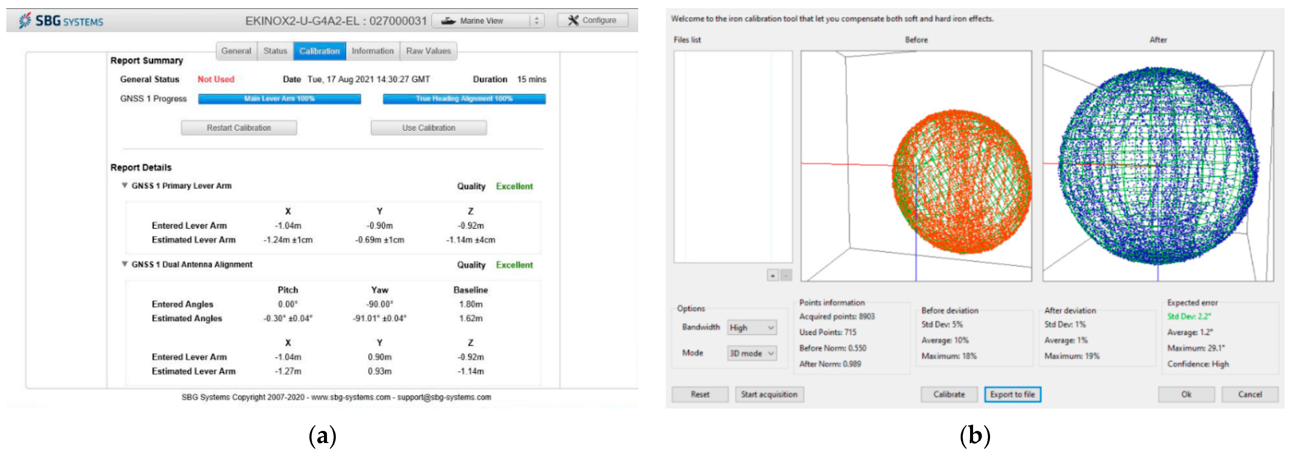
The GNSS/INS systems could then be calibrated. According to the SBG manufacturer’s recommendations for the Ekinox2-U system, calibration had to be performed in motion, with the assumption that its duration should be at least 15 min and the velocity of the “HydroDron” vessel’s movement should be no less than 10 km/h. Moreover, in order to calibrate all sensors (accelerometers and gyroscopes), it is recommended that the object should be moved in such a manner so as to constantly change the direction of movement. Movement in circles, ovals or the so-called “figure eights” is recommended. After 15 min of catamaran sailing, the calibration of the INS was completed. During the calibration, the geometric relationships between the external GNSS antennas and the IMU were determined in a precise manner (from ±1 to ±4 cm) (Figure 4a). As regards the latter of the systems applied, i.e., the Ellipse-D, the magnetometer needed to be calibrated in order to compensate for the effect of magnetic fields of other objects (mainly those on which it was installed). The accuracy of the IMU’s course is calculated by the quality of the calibration performed. If calibration is not conducted, the object’s course measurement error can be as much as several tens of degrees. The manufacturer recommends that the magnetic field measurements should be performed by means of rotating the IMU in significantly different orientations. It is recommended that at least 1000 points should be recorded in 9 different orientations, with the assumption that the IMU’s rotation velocity is approx. 45°/s. The progress of the calibration, including, e.g., where and how many points have been recorded, can be checked in the sbgCenter software in real-time. After performing the above steps, e.g., standard deviation of a single measurement of the IMU’s course is obtained. For the purposes of this study, it amounted to 2.2° RMS (Figure 4b).
Moreover, it was assumed that the Ekinox2-U system would apply the RTK method, while the Ellipse-D system would use the DGPS method to determine the vessel’s position. After saving the above settings, hydrographic surveys proceeded on Kłodno lake in Zawory in an unchanged form.

2.3. GNSS/INS Measurements

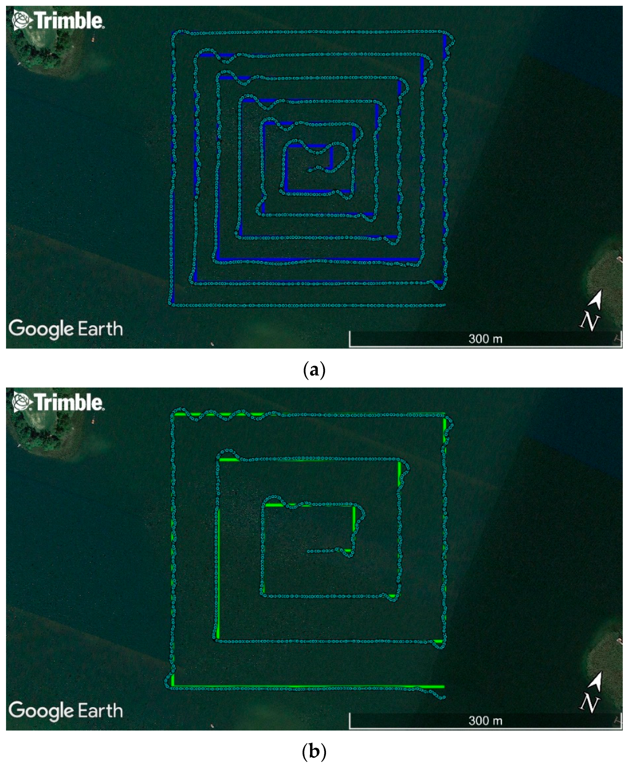
Once the assembly and implementation works were completed, measurements were carried out in order to determine the usefulness of GNSS/INS systems for hydrographic surveys. A study was conducted using the “HydroDron” vessel along the sounding profiles designed in accordance with the principles provided in the IHO S-44 standard [1]. The surveys were carried out on Kłodno lake in Zawory. Since the hydrometeorological conditions are an important factor affecting the obtained results, the measurements were performed in windless weather and the sea state was equal to 0, according to the Douglas scale (no wind waves or sea currents). For the surveys, an ASV/USV equipped with two GNSS/INS systems, models Ekinox2-U and Ellipse-D, was used to sail along the pre-designed test routes. The sounding profiles were conducted in relation to each other in two ways. The arrangement of both routes resembled “narrowing squares” (a spiral of) toward the centre of the waterbody being sounded. The distance between the successive polygons was constant and amounted to 25 m (Figure 5a) and 50 m (Figure 5b).
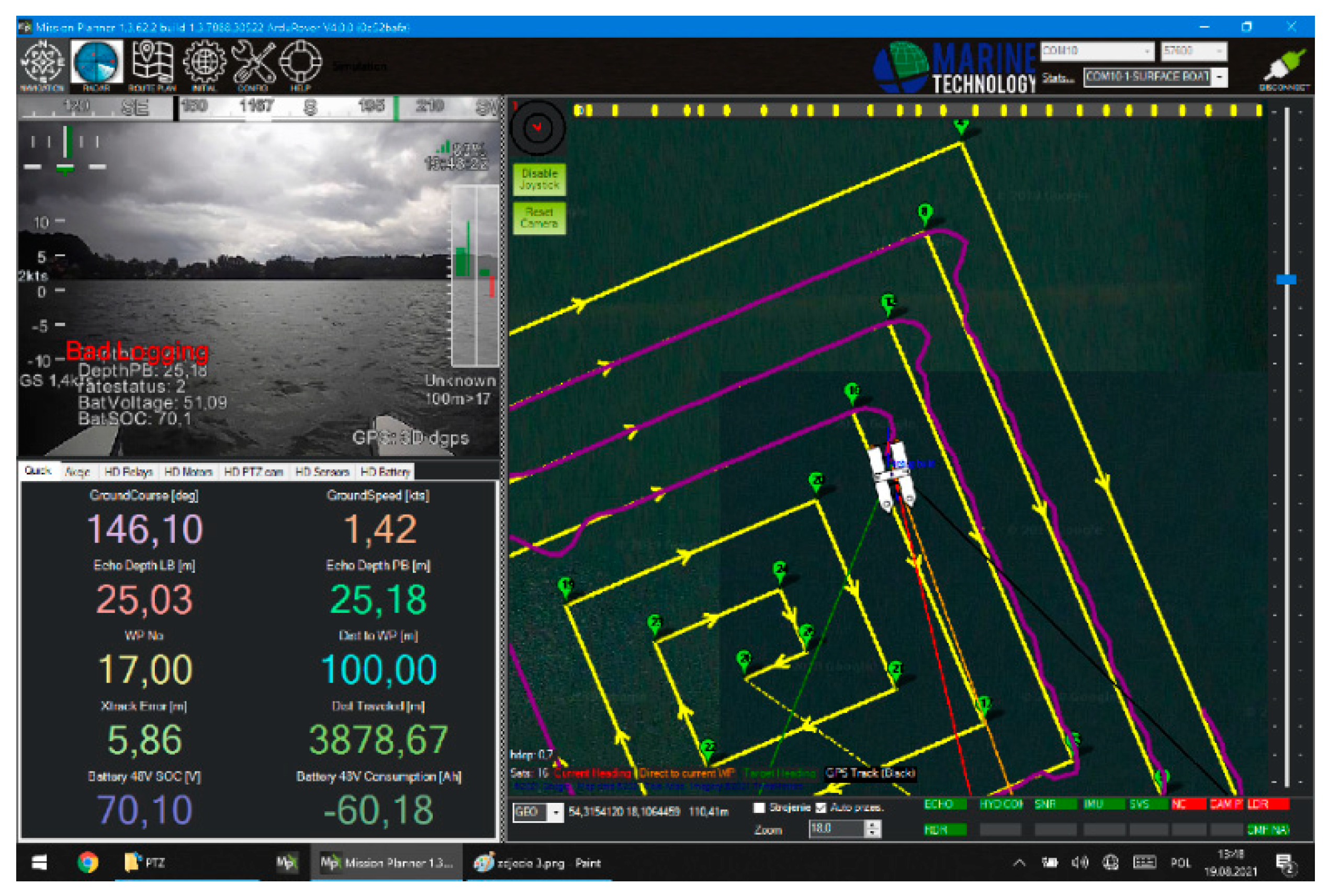
The routes were designed using the Trimble Business Center (TBC) software. The coordinates of the individual route’s turning points were then exported to two files in the *.WPT format. These points were recorded as geodetic coordinates referenced to the World Geodetic System 1984 (WGS-84) ellipsoid with an accuracy of nine decimal places. Later on, the data created in this way were converted to files in the *.SHP format dedicated to the ArduPilot Mission Planner software. This program is used for planning routes on which UAVs and USVs can move in an autonomous mode (Figure 6). The data prepared in this manner are transmitted through telemetry from the laptop on which the ArduPilot Mission Planner software is installed to the autopilot (Pixhawk 2.1) mounted on the “HydroDron”. After switching from the “Flight” mode to the “Auto” mode, the vessel starts sailing on the pre-determined points in an autonomous mode [78].
Once the routes were uploaded to the ArduPilot Mission Planner software, hydrographic surveys were started. The first route (Figure 5a) was covered between 10:55:18 a.m. and 12:01:57 p.m. Universal Time Coordinated (UTC). During this period, 4000 points were recorded with a sampling frequency of 1 Hz. The “HydroDron” sailed with an average velocity of 2.16 kn, and covered a distance of 4440 m. The second route (Figure 5b) was covered between 12:08:23 p.m. and 12:46:52 p.m. UTC. During this period, 2310 points were recorded with a sampling frequency of 1 Hz. The “HydroDron” sailed with an average velocity of 2.12 kn, and covered a distance of 2525 m.

2.4. GNSS/INS Data Processing

During two passages, data sets were acquired from two GNSS/INS systems. These recorded measurement results (point number, measurement time, ellipsoidal coordinates, RPY angles, course, standard deviations for a single measurement: 2D position, elevation, pitch, roll, yaw, course, etc.) and saved them in files in text form. The Ekinox2-U system recorded the data applying the RTK method, while the Ellipse-D system used the DGPS method with a sampling frequency of 1 Hz.
Each route was subjected to an identical data and statistical analysis, which will make it possible to draw general conclusions. The 1D, 2D and 3D position errors were uploaded into the Mathcad software, where it was statistically analysed to calculate the position accuracy measures (RMS, DRMS, 2DRMS, CEP, SEP, R68 and R95), which are commonly used in navigation. From the perspective of geodetic and navigation applications (land and marine) related to the object’s movement control, the most important measures should be 2DRMS(2D) and R95(2D), characterised by a high confidence level (95.4–98.2%) [79,80].
At the next stage of the analyses, the feasibility of using the DGPS and RTK systems in hydrography was assessed. To this end, a mathematical model developed in [81] was used to determine whether the requirements set out in the IHO S-44 standard were met [1]. The model was based on the theory of renewal (repair) process reliability, where the system’s operation and failure statistics are referred to as life and failure times that are subject to an exponential distribution [82].
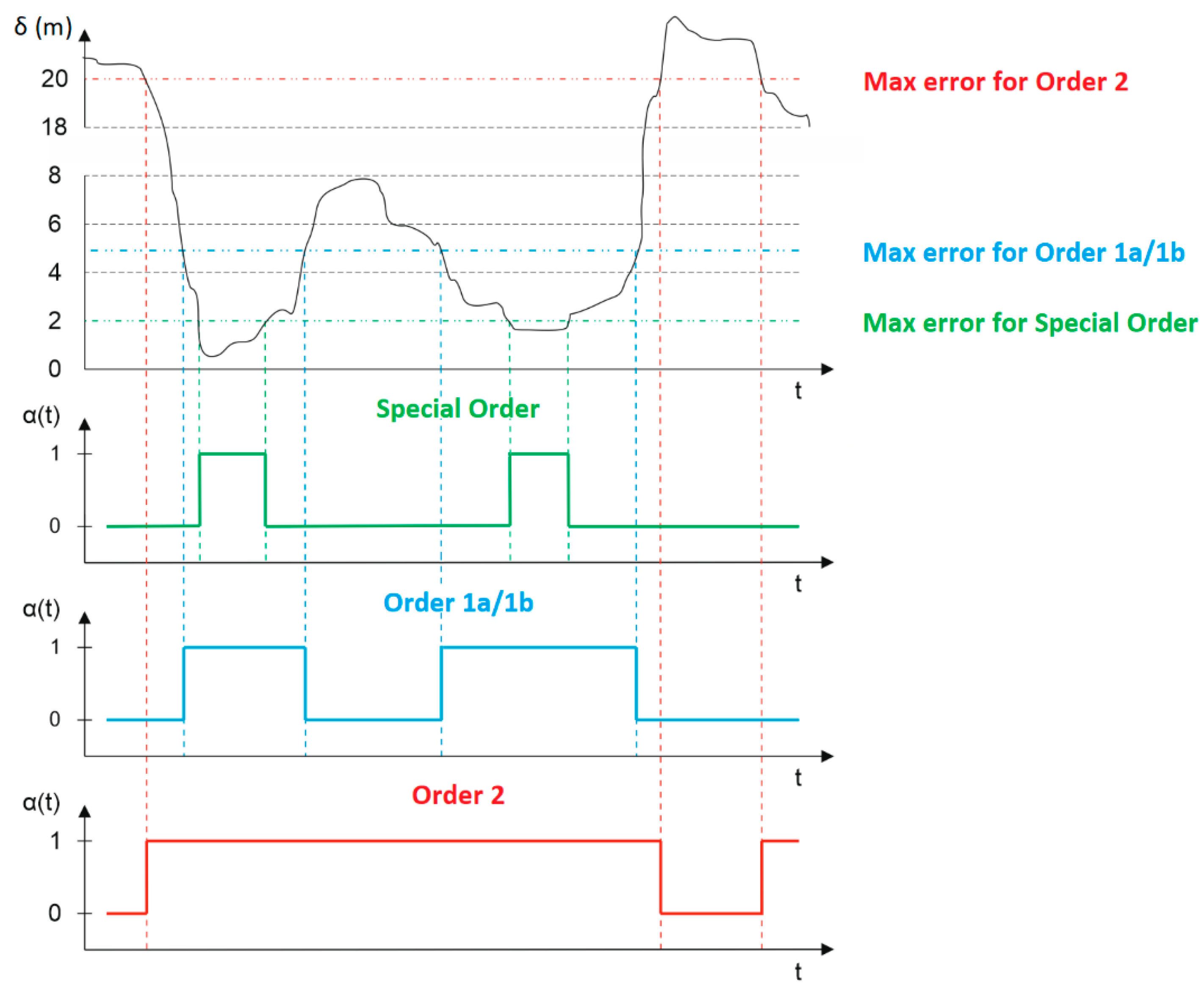
Let us consider a positioning system that determines a position with the error δn as a function of time, and for which four maximum permissible position error values, corresponding to the minimum accuracy requirements set out for the following four IHO orders: Special, 1a, 1b and 2, were determined. Figure 7 (the upper diagram) shows a curve that presents the position error value as a function of time for any positioning system. It allows us to assess whether any positioning system at a given point in time meets (or not) the accuracy requirements for each IHO order. Initially, the position error value exceeds 20 m, thereby preventing the system from meeting the requirements of any IHO order. After some time, this error value drops below 2 m, which results in the system meeting the requirements set out for the Special Order, etc. Below the position error diagram, three graphs are presented that show the system’s operational status from the perspective of meeting the requirements provided for IHO orders. If the system is assigned a binary value of 1, this means that it has a fitness (life) status. However, if the system is assigned a binary value of 0, this means that it has an unfitness (failure) status [82].

3. Results

Table 2 presents the IMU position accuracy results obtained on route no. 1.
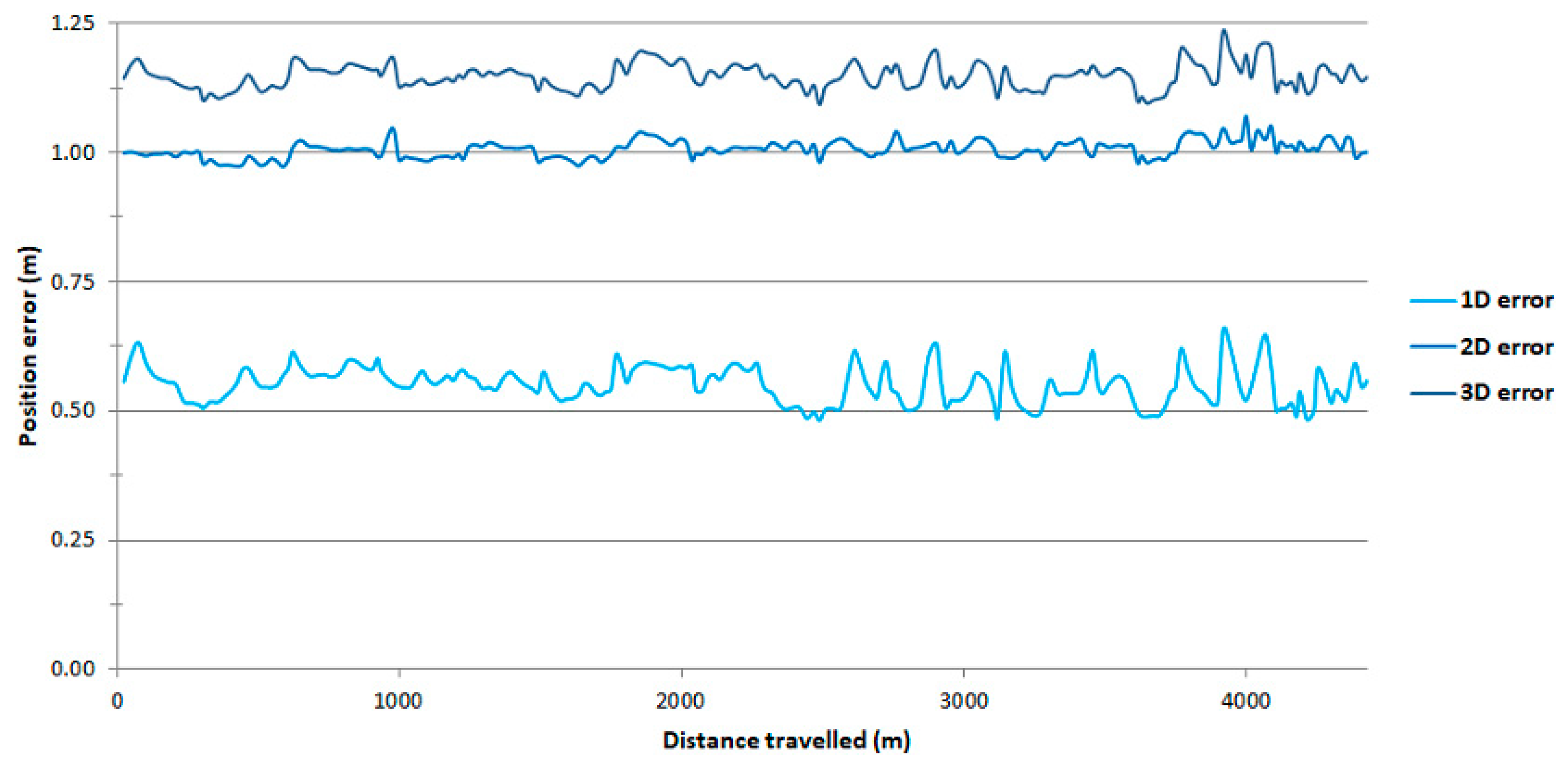
Based on Table 2, it can be concluded that the obtained position accuracy measures on route no. 1 are similar to those recommended by the SBG Systems. For example, the R68(2D) measure amounts to 0.032 m (Ekinox2-U) and 1.013 m (Ellipse-D). However, the R95(2D) measure amounts to 0.383 m (Ekinox2-U) and 1.036 m (Ellipse-D). It is noteworthy that the R95(2D) measure value for the Ekinox2-U system is considerably greater than expected. The reason for this is the loss of reception of RTK corrections for a period of approx. 7.5 min (a chainage of 1.49–2.06 km) (Figure 8).
As regards the Ellipse-D system, it should be stated that the variability of the 1D, 2D and 3D position errors is low along the entirety of route no. 1 (Figure 9). They fall within the following ranges: 0.482–0.657 m (for the 1D position error), 0.972–1.070 m (for the 2D position error) and 1.093–1.236 m (for the 3D position error).
In order to assess the reliability of the results obtaining during the performance of hydrographic surveys on route no. 1, it was decided to analyse the results of GNSS/INS measurements on route no. 2 (Table 3).
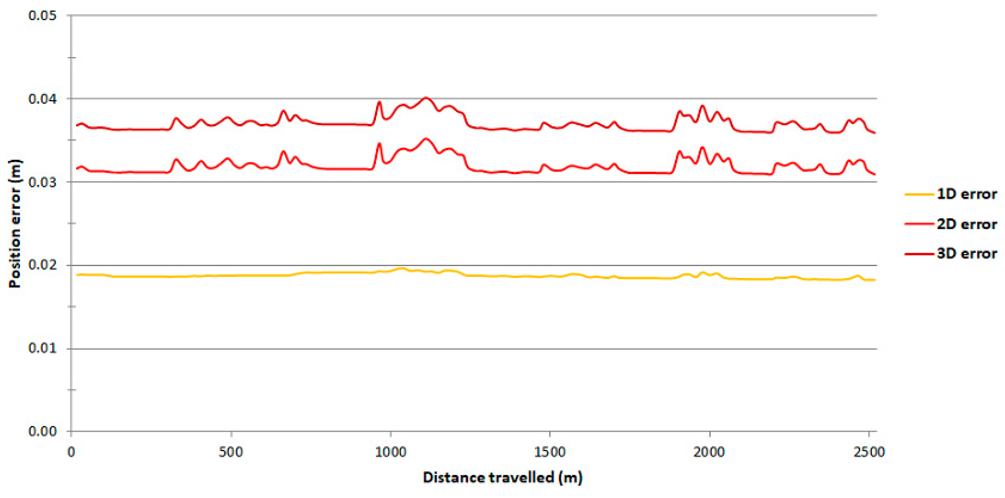
Based on Table 3, it can be concluded that the obtained position accuracy measured on route no. 2 are very similar to those recommended by the SBG Systems. For example, the R68(2D) measure amounts to 0.032 m (Ekinox2-U) and 1.032 m (Ellipse-D). However, the R95(2D) measure amounts to 0.034 m (Ekinox2-U) and 1.065 m (Ellipse-D). It is noteworthy that the individual position accuracy measures are almost identical to those obtained during the hydrographic surveys on route no. 1. The exception is the R95(2D) measure value for the Ekinox2-U system, which only differs from the R68(2D) measure by 2 mm. This is due to the fact that during the performance of hydrographic surveys, there was no loss in the reception of RTK corrections, which helped obtain the expected measurement results (Figure 10).
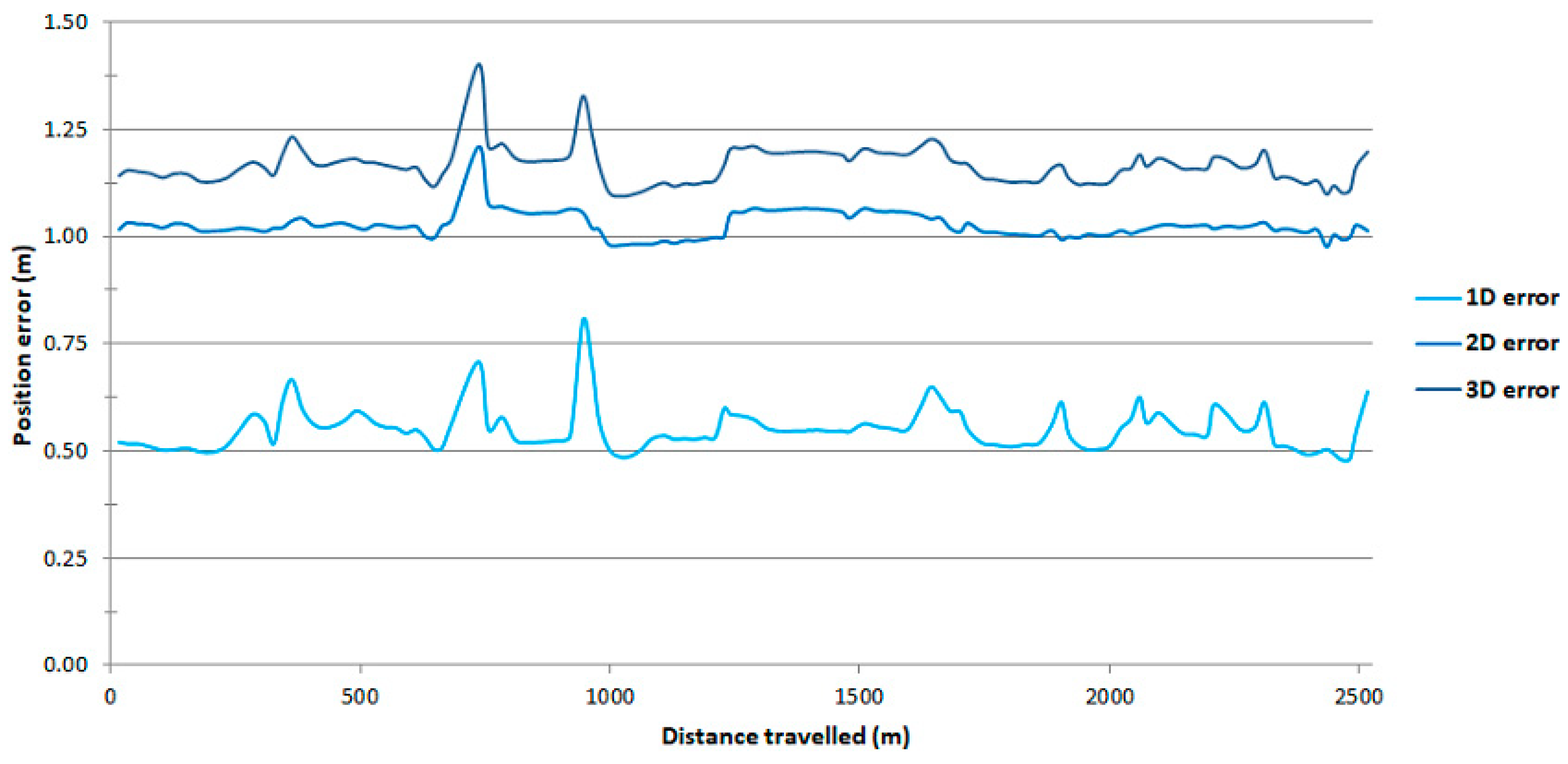
As regards the Ellipse-D system, it should be stated that the variability of the 1D, 2D and 3D position errors is low along the entirety of route no. 2 and is almost as low as that on route no. 1 (Figure 11). They fall within the following ranges: 0.478–0.804 m (for the 1D position error), 0.976–1.210 m (for the 2D position error) and 1.094–1.402 m (for the 3D position error).
Further on, we decided to use the mathematical model presented in [81]. Statistical analyses and calculations were carried out for the data recorded using the GNSS/INS systems. In addition, archival data from the DGPS measurements, conducted during the “Tucana” buoy tender’s manoeuvring in the Gdańsk Bay on 20 June 2017, were used. Those surveys used a Simrad MXB5 receiver [83]. For each IHO order, characterised by different permissible position errors, the availability factor value was calculated (Table 4).

4. Discussion

The analysis of the RTK results clearly proves that the system meets the positioning requirements provided for all the IHO orders, even in situations where it does not operate 100% correctly, e.g., due to the loss of reception of RTK corrections on route no. 1 (Figure 8). Hence, it can be applied during the implementation of hydrographic works, irrespective of the IHO order.
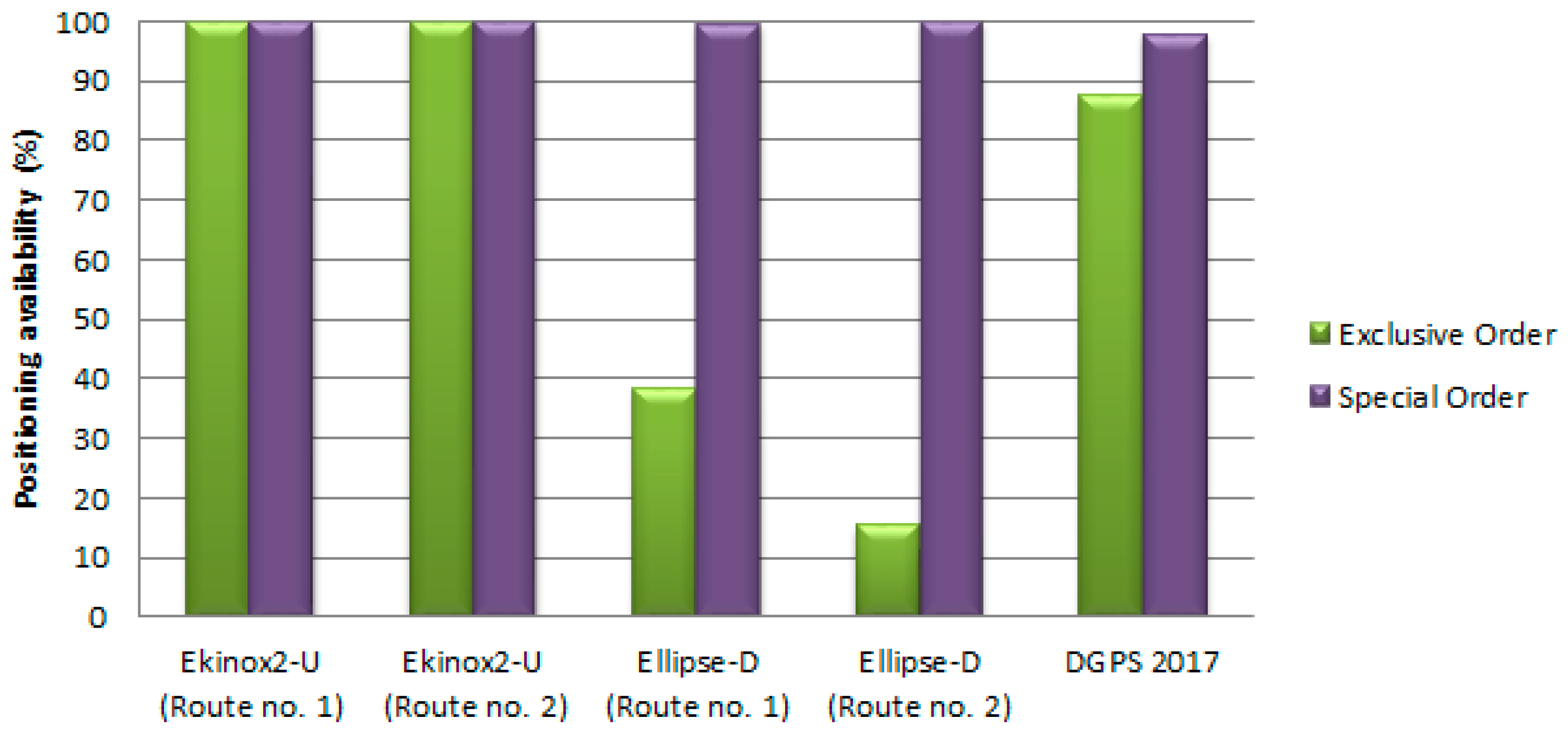
As regards the DGPS system, it must be pointed out that it easily meets the positioning requirements provided for four IHO orders (Special, 1a, 1b and 2). The availability factor value amounts to 100% almost every time. However, it should be noted that the DGPS system has not once reached the positioning availability required for the Exclusive Order, i.e., 38.48% (Ellipse-D (Route no. 1)), 15.54% (Ellipse-D (Route no. 2)) and 87.57% (DGPS 2017). Figure 12 shows graphs of the availability of individual positioning solutions broken down into the following two IHO orders: Exclusive and Special. The three other orders (1a, 1b and 2) require no separate analysis, as the interpretation of the results from Table 4 raises no doubts whatsoever.
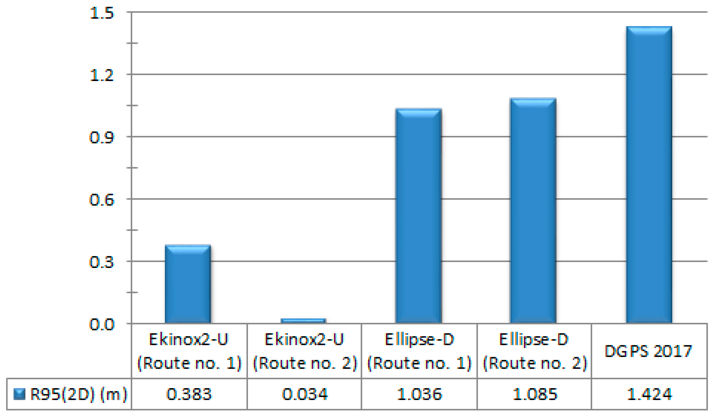
Since the DGPS system fails to meet the requirements provided for the most stringent IHO order, i.e., the Exclusive Order, we decided to calculate the 2D position error value for which the confidence level will be 95%. To this end, the R95(2D) measure was determined based on the data recorded during the performance of hydrographic surveys using GNSS/INS systems and tests for the DGPS system from 2017 (Figure 13).
Based on Figure 13, it can be concluded that the DGPS system permanently improves positioning characteristics, hence its use in hydrography will soon be possible for all the IHO orders. The R95(2D) measure for the Ellipse-D system amounts to 1.036 m (Route no. 1) and 1.085 m (Route no. 2), i.e., it exceeds the maximum permissible 2D position error provided for the Exclusive Order by only a few centimetres. However, the R95(2D) measure for the DGPS system from 2017 is noticeably higher and amounts to almost 1.5 m.

5. Conclusions

The study demonstrated that the GNSS/INS systems, which are additionally supported with RTK receivers, can be successfully used to carry out hydrographic surveys in any IHO order (Exclusive, Special, 1a, 1b and 2), even in situations where they do not operate 100% correctly, e.g., due to the loss of reception of RTK corrections on route no. 1 (Figure 8). However, the DGPS system fails to meet only the requirements provided for the most stringent IHO order, i.e., the Exclusive Order (horizontal position error ≤ 1 m (p = 0.95)). Statistical analyses showed that it only lacked 3.6 and 8.5 cm to meet this criterion (Figure 13). The above conclusions could be drawn due to the application of the mathematical model developed in [81]. It enables the determination of whether any positioning system, at a given point in time, meets (or does not meet) the accuracy requirements provided for individual IHO orders. A particular feature of the model is the possibility for an assessment based on the actual measurements and analyses of a positioning system’s operation and failure times.
The 1D, 2D and 3D position error values obtained using the GNSS/INS systems, models Ekinox2-U and Ellipse-D, are similar to the accuracy characteristics recommended by the SBG Systems. For example, the R68(2D) measure amounts to 0.032 m (Ekinox2-U) and 1.013–1.032 m (Ellipse-D). However, the R95(2D) measure amounts to 0.034–0.383 m (Ekinox2-U) and 1.036–1.065 m (Ellipse-D). It is noteworthy that almost all the position accuracy measures are identical during the performance of GNSS/INS measurements on both routes. The differences between the individual measures for the Ekinox2-U system are of an order of a few millimetres, while for the Ellipse-D system, they amount to a few centimetres.

Author Contributions

Conceptualisation, A.S., C.S. and M.S.; data curation, M.S., S.W., M.W. and O.L.; formal analysis, M.S., D.B. and A.J.; investigation, A.S., M.S., S.W., M.W. and O.L.; methodology, D.B. and A.J.; supervision, A.S. and C.S.; validation, C.S., D.B. and A.J.; visualisation, M.S., S.W., M.W. and O.L.; writing—original draft, A.S., C.S. and M.S.; writing—review and editing, D.B. and A.J. All authors have read and agreed to the published version of the manuscript.

Funding

This research was funded by the National Centre for Research and Development in Poland, grant number LIDER/10/0030/L-11/19/NCBR/2020. Moreover, this research was funded by the National Science Centre in Poland, grant number 2020/04/X/ST10/01777.

Institutional Review Board Statement

Not applicable.

Informed Consent Statement

Not applicable.

Data Availability Statement

Not applicable.

Conflicts of Interest

The authors declare no conflict of interest.

References

  1. IHO. IHO Standards for Hydrographic Surveys, 6th ed.; Special Publication No. 44; IHO: Monaco, Monaco, 2020. [Google Scholar]
  2. Li, W.; Liu, G.; Cui, X.; Lu, M. Feature-aided RTK/LiDAR/INS Integrated Positioning System with Parallel Filters in the Ambiguity-position-joint Domain for Urban Environments. Remote Sens. 2021, 13, 2013. [Google Scholar] [CrossRef]
  3. Won, D.H.; Lee, E.; Heo, M.; Lee, S.-W.; Lee, J.; Kim, J.; Sung, S.; Jae, Y. Selective Integration of GNSS, Vision Sensor, and INS Using Weighted DOP Under GNSS-challenged Environments. IEEE Trans. Instrum. Meas. 2014, 63, 2288–2298. [Google Scholar] [CrossRef]
  4. Yan, P.; Jiang, J.; Tang, Y.; Zhang, F.; Xie, D.; Wu, J.; Liu, J.; Liu, J. Dynamic Adaptive Low Power Adjustment Scheme for Single-frequency GNSS/MEMS-IMU/Odometer Integrated Navigation in the Complex Urban Environment. Remote Sens. 2021, 13, 3236. [Google Scholar] [CrossRef]
  5. Broumandan, A.; Lachapelle, G. Spoofing Detection Using GNSS/INS/Odometer Coupling for Vehicular Navigation. Sensors 2018, 18, 1305. [Google Scholar] [CrossRef] [PubMed] [Green Version]
  6. Vagle, N.; Broumandan, A.; Lachapelle, G. Multi-antenna GNSS and Inertial Sensors/Odometer Coupling for Robust Vehicular Navigation. IEEE Internet Things J. 2018, 5, 4816–4828. [Google Scholar] [CrossRef]
  7. Yang, L.; Li, Y.; Wu, Y.; Rizos, C. An Enhanced MEMS-INS/GNSS Integrated System with Fault Detection and Exclusion Capability for Land Vehicle Navigation in Urban Areas. GPS Solutions 2014, 18, 593–603. [Google Scholar] [CrossRef]
  8. Brazeal, R.G.; Wilkinson, B.E.; Benjamin, A.R. Investigating Practical Impacts of Using Single-antenna and Dual-antenna GNSS/INS Sensors in UAS-Lidar Applications. Sensors 2021, 21, 5382. [Google Scholar] [CrossRef] [PubMed]
  9. Mwenegoha, H.A.; Moore, T.; Pinchin, J.; Jabbal, M. A Model-based Tightly Coupled Architecture for Low-cost Unmanned Aerial Vehicles for Real-time Applications. IEEE Access 2020, 1–20. [Google Scholar] [CrossRef]
  10. Naus, K.; Szymak, P.; Piskur, P.; Niedziela, M.; Nowak, A. Methodology for the Correction of the Spatial Orientation Angles of the Unmanned Aerial Vehicle Using Real Time GNSS, a Shoreline Image and an Electronic Navigational Chart. Energies 2021, 14, 2810. [Google Scholar] [CrossRef]
  11. Wang, Q.; Cui, X.; Li, Y.; Ye, F. Performance Enhancement of a USV INS/CNS/DVL Integration Navigation System Based on an Adaptive Information Sharing Factor Federated Filter. Sensors 2017, 17, 239. [Google Scholar] [CrossRef] [PubMed] [Green Version]
  12. Xia, G.; Wang, G. INS/GNSS Tightly-Coupled Integration Using Quaternion-based AUPF for USV. Sensors 2016, 16, 1215. [Google Scholar] [CrossRef] [Green Version]
  13. Yan, W.; Zhang, Q.; Zhang, Y.; Wang, A.; Zhao, C. The Validation and Performance Assessment of the Android Smartphone Based GNSS/INS Coupled Navigation System. In Proceedings of the 12th China Satellite Navigation Conference (CSNC 2021), Nanchang, China, 22–25 May 2021. [Google Scholar]
  14. Li, N.; Guan, L.; Gao, Y.; Du, S.; Wu, M.; Guang, X.; Cong, X. Indoor and Outdoor Low-cost Seamless Integrated Navigation System Based on the Integration of INS/GNSS/LIDAR System. Remote Sens. 2020, 12, 3271. [Google Scholar] [CrossRef]
  15. Zhuang, Y.; Lan, H.; Li, Y.; El-Sheimy, N. PDR/INS/WiFi Integration Based on Handheld Devices for Indoor Pedestrian Navigation. Micromachines 2015, 6, 793–812. [Google Scholar] [CrossRef] [Green Version]
  16. Jing, S.; Zhan, X.; Liu, B.; Chen, M. Weak and Dynamic GNSS Signal Tracking Strategies for Flight Missions in the Space Service Volume. Sensors 2016, 16, 1412. [Google Scholar] [CrossRef] [PubMed] [Green Version]
  17. Barzaghi, R.; Carrion, D.; Pepe, M.; Prezioso, G. Computing the Deflection of the Vertical for Improving Aerial Surveys: A Comparison between EGM2008 and ITALGEO05 Estimates. Sensors 2016, 16, 1168. [Google Scholar] [CrossRef] [PubMed] [Green Version]
  18. Pytka, J.; Budzyński, P.; Józwik, J.; Michałowska, J.; Tofil, A.; Łyszczyk, T.; Błażejczak, D. Application of GNSS/INS and an Optical Sensor for Determining Airplane Takeoff and Landing Performance on a Grassy Airfield. Sensors 2019, 19, 5492. [Google Scholar] [CrossRef] [PubMed] [Green Version]
  19. Qian, C.; Liu, H.; Tang, J.; Chen, Y.; Kaartinen, H.; Kukko, A.; Zhu, L.; Liang, X.; Chen, L.; Hyyppä, J. An Integrated GNSS/INS/LiDAR-SLAM Positioning Method for Highly Accurate Forest Stem Mapping. Remote Sens. 2017, 9, 3. [Google Scholar] [CrossRef] [Green Version]
  20. El-Diasty, M. Development of Real-time PPP-based GPS/INS Integration System Using IGS Real-time Service for Hydrographic Surveys. J. Surv. Eng. 2016, 142, 05015005. [Google Scholar] [CrossRef]
  21. El-Diasty, M. Evaluation of KSACORS-based Network GNSS-INS Integrated System for Saudi Coastal Hydrographic Surveys. Geomat. Nat. Hazards Risk 2020, 11, 1426–1446. [Google Scholar] [CrossRef]
  22. Scheider, A.; Wirth, H.; Breitenfeld, M.; Schwieger, V. HydrOs—An Integrated Hydrographic Positioning System for Surveying Vessels. In Proceedings of the XXV FIG Congress 2014, Kuala Lumpur, Malaysia, 16–21 June 2014. [Google Scholar]
  23. Bedkowski, J.; Nowak, H.; Kubiak, B.; Studzinski, W.; Janeczek, M.; Karas, S.; Kopaczewski, A.; Makosiej, P.; Koszuk, J.; Pec, M.; et al. A Novel Approach to Global Positioning System Accuracy Assessment, Verified on LiDAR Alignment of One Million Kilometers at a Continent Scale, as a Foundation for Autonomous DRIVING Safety Analysis. Sensors 2021, 21, 5691. [Google Scholar] [CrossRef]
  24. Elsheikh, M.; Abdelfatah, W.; Noureldin, A.; Iqbal, U.; Korenberg, M. Low-cost Real-time PPP/INS Integration for Automated Land Vehicles. Sensors 2019, 19, 4896. [Google Scholar] [CrossRef] [Green Version]
  25. Zhu, F.; Shen, Y.; Wang, Y.; Jia, J.; Zhang, X. Fusing GNSS/INS/Vision with a Priori Feature Map for High-precision and Continuous Navigation. IEEE Sens. J. 2021, 21, 23370–23381. [Google Scholar] [CrossRef]
  26. Sun, Z.; Tang, K.; Wang, X.; Wu, M.; Guo, Y. High-speed Train Tunnel Navigation Method Based on Integrated MIMU/ODO/MC Navigation. Appl. Sci. 2021, 11, 3680. [Google Scholar] [CrossRef]
  27. Sun, Z.; Tang, K.; Wu, M.; Guo, Y.; Wang, X. High-speed Train Positioning Method Based on Motion Constraints Suppressing INS Error in Tunnel. J. Northwest. Polytech. Univ. 2021, 39, 624–632. [Google Scholar] [CrossRef]
  28. Chen, K.; Chang, G.; Chen, C. GINav: A MATLAB-based Software for the Data Processing and Analysis of a GNSS/INS Integrated Navigation System. GPS Solutions 2021, 25, 108. [Google Scholar] [CrossRef]
  29. Du, S.; Zhang, S.; Gan, X. A Hybrid Fusion Strategy for the Land Vehicle Navigation Using MEMS INS, Odometer and GNSS. IEEE Access 2020, 8, 152512–152522. [Google Scholar] [CrossRef]
  30. Elmezayen, A.; El-Rabbany, A. Ultra-low-cost Tightly Coupled Triple-constellation GNSS PPP/MEMS-based INS Integration for Land Vehicular Applications. Geomatics 2021, 1, 258–286. [Google Scholar] [CrossRef]
  31. Dong, P.; Cheng, J.; Liu, L. A Novel Anti-jamming Technique for INS/GNSS Integration Based on Black Box Variational Inference. Appl. Sci. 2021, 11, 3664. [Google Scholar] [CrossRef]
  32. Kujur, B.; Khanafseh, S.; Pervan, B. Detecting GNSS Spoofing of ADS-B Equipped Aircraft Using INS. In Proceedings of the 2020 IEEE/ION Position, Location and Navigation Symposium (PLANS 2020), Portland, OR, USA, 20–23 April 2020. [Google Scholar]
  33. Specht, C.; Specht, M.; Dąbrowski, P. Comparative Analysis of Active Geodetic Networks in Poland. In Proceedings of the 17th International Multidisciplinary Scientific GeoConference (SGEM 2017), Albena, Bulgaria, 27 June–6 July 2017. [Google Scholar]
  34. Mora, O.E.; Langford, M.; Mislang, R.; Josenhans, R.; Jorge Chen, J. Precision Performance Evaluation of RTK and RTN Solutions: A Case Study. J. Spat. Sci. 2020, 1–14. [Google Scholar] [CrossRef]
  35. Bakuła, M. Study of Reliable Rapid and Ultrarapid Static GNSS Surveying for Determination of the Coordinates of Control Points in Obstructed Conditions. J. Surv. Eng. 2013, 139, 188–193. [Google Scholar] [CrossRef]
  36. Bogusz, J.; Figurski, M.; Kontny, B.; Grzempowski, P. Horizontal Velocity Field Derived from EPN and ASG-EUPOS Satellite Data on the Example of South-western Part of Poland. Acta Geodyn. Geomater. 2012, 9, 349–357. [Google Scholar]
  37. Stępniak, K.; Baryła, R.; Wielgosz, P.; Kurpiński, G. Optimal Data Processing Strategy in Precise GPS Levelling Networks. Acta Geodyn. Geomater. 2013, 10, 443–452. [Google Scholar] [CrossRef] [Green Version]
  38. Ćwiąkała, P.; Gabryszuk, J.; Krawczyk, K.; Krzyżek, R.; Leń, P.; Oleniacz, G.; Puchniach, E.; Siejka, Z.; Wójcik-Leń, J. GNSS Technology and Its Application in Setting out Surveys and Monitoring; Rzeszów School of Engineering and Economics Publishing House: Rzeszów, Poland, 2015. (In Polish) [Google Scholar]
  39. Przestrzelski, P.; Bakuła, M. Performance of Real-time Network Code DGPS Services of ASG-EUPOS in North-Eastern Poland. Tech. Sci. 2014, 17, 191–207. [Google Scholar]
  40. Specht, C.; Rudnicki, J. A Method for the Assessing of Reliability Characteristics Relevant to an Assumed Position-fixing Accuracy in Navigational Positioning Systems. Pol. Marit. Res. 2016, 23, 20–27. [Google Scholar] [CrossRef] [Green Version]
  41. Visconti, P.; Iaia, F.; De Fazio, R.; Giannoccaro, N.I. A Stake-out Prototype System Based on GNSS-RTK Technology for Implementing Accurate Vehicle Reliability and Performance Tests. Energies 2021, 14, 4885. [Google Scholar] [CrossRef]
  42. Bakuła, M.; Pelc-Mieczkowska, R.; Walawski, M. Reliable and Redundant RTK Positioning for Applications in Hard Observational Conditions. Artif. Satell. 2012, 47, 23–33. [Google Scholar] [CrossRef]
  43. Janos, D.; Kuras, P. Evaluation of Low-cost GNSS Receiver under Demanding Conditions in RTK Network Mode. Sensors 2021, 21, 5552. [Google Scholar] [CrossRef] [PubMed]
  44. IALA. IALA Recommendation R-121 on the Performance and Monitoring of DGNSS Services in the Frequency Band 283.5–325 kHz, 2.0 ed.; IALA: Saint-Germain-en-Laye, France, 2015. [Google Scholar]
  45. Specht, C.; Weintrit, A.; Specht, M. A History of Maritime Radio-navigation Positioning Systems Used in Poland. J. Navig. 2016, 69, 468–480. [Google Scholar] [CrossRef] [Green Version]
  46. Dziewicki, M.; Specht, C. Position Accuracy Evaluation of the Modernized Polish DGPS. Pol. Marit. Res. 2009, 16, 57–61. [Google Scholar] [CrossRef]
  47. Kim, J.; Song, J.; No, H.; Han, D.; Kim, D.; Park, B.; Kee, C. Accuracy Improvement of DGPS for Low-cost Single-frequency Receiver Using Modified Flachen Korrektur Parameter Correction. ISPRS Int. J. Geo-Inf. 2017, 6, 222. [Google Scholar] [CrossRef] [Green Version]
  48. Lubis, M.Z.; Anggraini, K.; Kausarian, H.; Pujiyati, S. Review: Marine Seismic and Side-scan Sonar Investigations for Seabed Identification with Sonar System. J. Geosci. Eng. Environ. Technol. 2017, 2, 166–170. [Google Scholar] [CrossRef] [Green Version]
  49. Ratheesh, R.; Ritesh, A.; Remya, P.G.; Nagakumar, K.C.V.; Demudu, G.; Rajawat, A.S.; Nair, B.; Nageswara Rao, K. Modelling Coastal Erosion: A Case Study of Yarada Beach Near Visakhapatnam, East Coast of India. Ocean. Coast. Manag. 2018, 156, 239–248. [Google Scholar]
  50. Ward, R.D.; Burnside, N.G.; Joyce, C.B.; Sepp, K.; Teasdale, P.A. Improved Modelling of the Impacts of Sea Level Rise on Coastal Wetland Plant Communities. Hydrobiologia 2016, 774, 203–216. [Google Scholar] [CrossRef] [Green Version]
  51. Honarmand, M.; Shahriari, H. Geological Mapping Using Drone-based Photogrammetry: An Application for Exploration of Vein-type Cu Mineralization. Minerals 2021, 11, 585. [Google Scholar] [CrossRef]
  52. Ji, S.; Gao, Z.; Wang, W. M-DGPS: Mobile Devices Supported Differential Global Positioning System Algorithm. Arab. J. Geosci. 2015, 8, 6667–6675. [Google Scholar] [CrossRef]
  53. Yoon, D.; Kee, C.; Seo, J.; Park, B. Position Accuracy Improvement by Implementing the DGNSS-CP Algorithm in Smartphones. Sensors 2016, 16, 910. [Google Scholar] [CrossRef] [PubMed] [Green Version]
  54. Krasuski, K.; Popielarczyk, D.; Ciećko, A.; Ćwiklak, J. A New Strategy for Improving the Accuracy of Aircraft Positioning Using DGPS Technique in Aerial Navigation. Energies 2021, 14, 4431. [Google Scholar] [CrossRef]
  55. Yoon, H.; Seok, H.; Lim, C.; Park, B. An Online SBAS Service to Improve Drone Navigation Performance in High-elevation Masked Areas. Sensors 2020, 20, 3047. [Google Scholar] [CrossRef]
  56. Chen, H.; Moan, T.; Verhoeven, H. Effect of DGPS Failures on Dynamic Positioning of Mobile Drilling Units in the North Sea. Accid. Anal. Prev. 2009, 41, 1164–1171. [Google Scholar] [CrossRef]
  57. Kim, Y.W. DGPS Service Analysis in the Korean Coastal Ferry Route. J. Korea Inst. Inf. Commun. Eng. 2014, 18, 2073–2078. [Google Scholar] [CrossRef] [Green Version]
  58. Moore, T.; Hill, C.; Monteiro, L. Is DGPS Still a Good Option for Mariners? J. Navig. 2001, 54, 437–446. [Google Scholar] [CrossRef]
  59. Ibrahim, P.O.; Sternberg, H. Bathymetric Survey for Enhancing the Volumetric Capacity of Tagwai Dam in Nigeria via Leapfrogging Approach. Geomatics 2021, 1, 246–257. [Google Scholar] [CrossRef]
  60. Bini, M.; Casarosa, N.; Luppichini, M. Exploring the Relationship between River Discharge and Coastal Erosion: An Integrated Approach Applied to the Pisa Coastal Plain (Italy). Remote Sens. 2021, 13, 226. [Google Scholar] [CrossRef]
  61. Frati, G.; Launeau, P.; Robin, M.; Giraud, M.; Juigner, M.; Debaine, F.; Michon, C. Coastal Sand Dunes Monitoring by Low Vegetation Cover Classification and Digital Elevation Model Improvement Using Synchronized Hyperspectral and Full-waveform LiDAR Remote Sensing. Remote Sens. 2021, 13, 29. [Google Scholar] [CrossRef]
  62. Rathour, S.S.; Boyali, A.; Zheming, L.; Mita, S.; John, V. A Map-based Lateral and Longitudinal DGPS/DR Bias Estimation Method for Autonomous Driving. Int. J. Mach. Learn. Comput. 2017, 7, 67–71. [Google Scholar] [CrossRef]
  63. Ssebazza, L.; Pan, Y.J. DGPS-based Localization and Path Following Approach for Outdoor Wheeled Mobile Robots. Int. J. Robot. Autom. 2015, 30, 13–25. [Google Scholar] [CrossRef]
  64. Vetrella, A.R.; Fasano, G.; Accardo, D.; Moccia, A. Differential GNSS and Vision-based Tracking to Improve Navigation Performance in Cooperative Multi-UAV Systems. Sensors 2016, 16, 2164. [Google Scholar] [CrossRef] [PubMed]
  65. Liu, J.; Wang, L.; Teng, F.; Li, D.; Wang, X.; Cao, H. Crop Area Ground Sample Survey Using Google Earth Image-aided. Trans. Chin. Soc. Agric. Eng. 2015, 31, 149–154. [Google Scholar]
  66. Muhammad, S.; Tian, L. Hunza, Gilgit and Astore Valley Glacier Elevation Changes During 2003 to 2014 Using ICESat and DGPS Data. In Proceedings of the International Symposium on Glaciology in High-mountain Asia, Kathmandu, Nepal, 1–6 March 2015. [Google Scholar]
  67. Galan-Martin, D.; Marchamalo-Sacristan, M.; Martinez-Marin, R.; Sanchez-Sobrino, J.A. Geomatics Applied to Dam Safety DGPS Real Time Monitoring. Int. J. Civ. Eng. 2013, 11, 134–141. [Google Scholar]
  68. Malinowski, M. Precise Point Positioning (PPP) Accuracy Using Online Web Services. J. Civil. Eng. Environ. Archit. 2017, 64, 297–313. [Google Scholar]
  69. Zhang, B.; Chen, Y.; Yuan, Y. PPP-RTK Based on Undifferenced and Uncombined Observations: Theoretical and Practical Aspects. J. Geod. 2019, 93, 1011–1024. [Google Scholar] [CrossRef]
  70. Zhang, B.; Hou, P.; Zha, J.; Liu, T. Integer-estimable FDMA Model as an Enabler of GLONASS PPP-RTK. J. Geod. 2021, 95, 91. [Google Scholar] [CrossRef]
  71. Akpınar, B.; Aykut, N.O. Determining the Coordinates of Control Points in Hydrographic Surveying by the Precise Point Positioning Method. J. Navig. 2017, 70, 1241–1252. [Google Scholar] [CrossRef]
  72. Erol, S.; Alkan, R.M.; Ozulu, İ.M.; İlçi, V. Performance Analysis of Real-time and Post-mission Kinematic Precise Point Positioning in Marine Environments. Geod. Geodyn. 2020, 11, 401–410. [Google Scholar] [CrossRef]
  73. Seonghyeon, Y.; Hungkyu, L.; Yunsoo, C.; Geonwoo, H. Potential Accuracy of GNSS PPP- and PPK-derived Heights for Ellipsoidally Referenced Hydrographic Surveys: Experimental Assessment and Results. J. Position. Navig. Timing 2017, 6, 211–221. [Google Scholar]
  74. Specht, M.; Stateczny, A.; Specht, C.; Widźgowski, S.; Lewicka, O.; Wiśniewska, M. Concept of an Innovative Autonomous Unmanned System for Bathymetric Monitoring of Shallow Waterbodies (INNOBAT System). Energies 2021, 14, 5370. [Google Scholar] [CrossRef]
  75. SBG Systems. Ekinox Series. Available online: https://www.sbg-systems.com/products/ekinox-series/ (accessed on 5 November 2021).
  76. SBG Systems. Ellipse Series. Available online: https://www.sbg-systems.com/products/ellipse-series/ (accessed on 5 November 2021).
  77. Stateczny, A.; Kazimierski, W.; Burdziakowski, P.; Motyl, W.; Wisniewska, M. Shore Construction Detection by Automotive Radar for the Needs of Autonomous Surface Vehicle Navigation. ISPRS Int. J. Geo-Inf. 2019, 8, 80. [Google Scholar] [CrossRef] [Green Version]
  78. Specht, M.; Specht, C.; Lasota, H.; Cywiński, P. Assessment of the Steering Precision of a Hydrographic Unmanned Surface Vessel (USV) along Sounding Profiles Using a Low-cost Multi-Global Navigation Satellite System (GNSS) Receiver Supported Autopilot. Sensors 2019, 19, 3939. [Google Scholar] [CrossRef] [Green Version]
  79. Specht, M.; Specht, C.; Dąbrowski, P.; Czaplewski, K.; Smolarek, L.; Lewicka, O. Road Tests of the Positioning Accuracy of INS/GNSS Systems Based on MEMS Technology for Navigating Railway Vehicles. Energies 2020, 13, 4463. [Google Scholar] [CrossRef]
  80. Szot, T.; Specht, C.; Specht, M.; Dabrowski, P.S. Comparative Analysis of Positioning Accuracy of Samsung Galaxy Smartphones in Stationary Measurements. PLoS ONE 2019, 14, e0215562. [Google Scholar] [CrossRef] [PubMed]
  81. Specht, M. Method of Evaluating the Positioning System Capability for Complying with the Minimum Accuracy Requirements for the International Hydrographic Organization Orders. Sensors 2019, 19, 3860. [Google Scholar] [CrossRef] [PubMed] [Green Version]
  82. Specht, C. Availability, Reliability and Continuity Model of Differential GPS Transmission. Annu. Navig. 2003, 5, 1–85. [Google Scholar]
  83. Specht, C.; Pawelski, J.; Smolarek, L.; Specht, M.; Dąbrowski, P. Assessment of the Positioning Accuracy of DGPS and EGNOS Systems in the Bay of Gdansk Using Maritime Dynamic Measurements. J. Navig. 2019, 72, 575–587. [Google Scholar] [CrossRef] [Green Version]
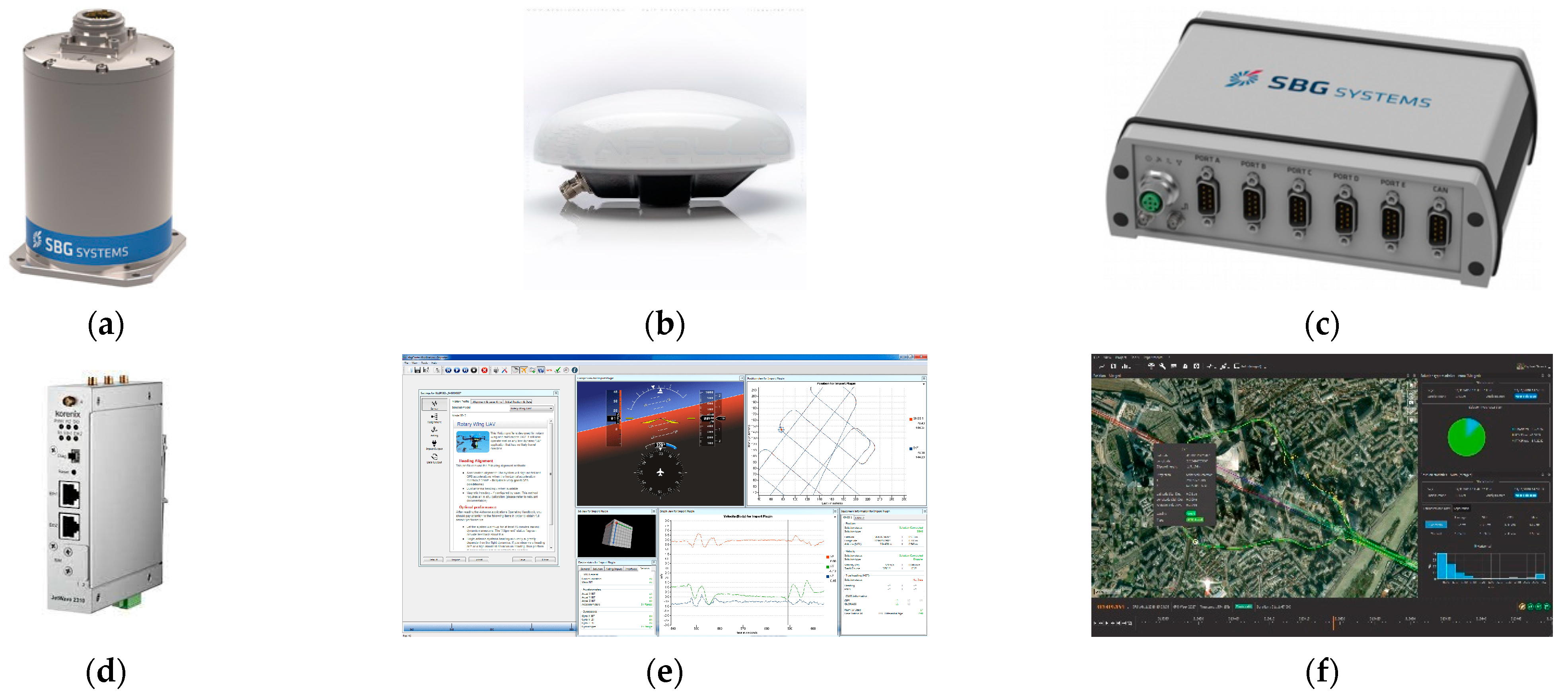
Figure 1. Components of the GNSS/INS system, model Ekinox2-U, by the SBG Systems: (a) IMU, (b) GNSS antennas, (c) SplitBox computer system, (d) modem enabling the reception of RTK/RTN corrections, (e) sbgCenter software and (f) Qinertia software [75].
Energies 14 07413 g001
Figure 2. Components of the GNSS/INS system, model Ellipse-D, by the SBG Systems: (a) IMU, (b) GNSS antennas and (c) sbgCenter software [76].
Energies 14 07413 g002
Figure 3. The arrangement of the GNSS/INS systems on the Autonomous Surface Vehicle (ASV)/USV named “HydroDron”: (a) view from the front of the vessel and (b) view on IMUs.
Energies 14 07413 g003
Figure 4. The calibration results of the GNSS/INS systems, models (a) Ekinox2-U and (b) Ellipse-D as of 19 August 2021.
Energies 14 07413 g004
Figure 5. Arrangement of the route’s sounding profiles—spiral every (a) 25 m and (b) 50 m, on which the ASV/USV moved during the hydrographic surveys. The “HydroDron” vessel’s trajectory was marked with a sky-blue colour.
Energies 14 07413 g005
Figure 6. Window of the ArduPilot Mission Planner application used for the planning and recording of a vessel’s route.
Energies 14 07413 g006
Figure 7. The position error as a function of time (the upper diagram) and three diagrams corresponding to the operational status for the following IHO orders: Special (green colour), 1a/1b (blue colour) and 2 (red colour) [81].
Energies 14 07413 g007
Figure 8. Variability of the 1D, 2D and 3D position errors recorded using the Ekinox2-U system in the RTK mode on route no. 1.
Energies 14 07413 g008
Figure 9. Variability of the 1D, 2D and 3D position errors recorded using the Ellipse-D system in the DGPS mode on route no. 1.
Energies 14 07413 g009
Figure 10. Variability of the 1D, 2D and 3D position errors recorded using the Ekinox2-U system in the RTK mode on route no. 2.
Energies 14 07413 g010
Figure 11. Variability of the 1D, 2D and 3D position errors recorded using the Ellipse-D system in the DGPS mode on route no. 2.
Energies 14 07413 g011
Figure 12. The availability factor values determined for the GNSS/INS systems in the context of minimum positioning requirements, set for the two most stringent IHO orders.
Energies 14 07413 g012
Figure 13. The R95(2D) measure values for the GNSS/INS systems on individual routes, and for the DGPS system from 2017.
Energies 14 07413 g013
Table 1. Accuracy characteristics of the GNSS/INS systems, models Ekinox2-U and Ellipse-D in the case of access to and no access to a GNSS signal [75,76].
Measurement ErrorTime That Has Elapsed Since the GNSS Signal Was Not Available
0 s10 s
Ellipse-DEkinox2-UEllipse-DEkinox2-U
DGPSRTKDGPSRTKDGPSRTKDGPSRTK
σ2D (m)1.20.011.20.013120.35
σH (m)1.50.0220.023.5130.15
σβ, σα (°)0.10.050.050.050.10.050.10.1
σδ (°)0.80.20.10.050.80.20.150.1
Where: σ2D—standard deviation of a single measurement of the 2D position of the IMU, σH—standard deviation of a single measurement of the IMU’s height, σβ—standard deviation of a single measurement of the IMU’s pitch, σα—standard deviation of a single measurement of the IMU’s roll, σδ—standard deviation of a single measurement of the IMU’s course.
Table 2. The position accuracy measures of the GNSS/INS systems, models Ekinox2-U and Ellipse-D, during the hydrographic surveys on route no. 1.
Statistics of Position ErrorGNSS SystemType of Registered Data
Ekinox2-UEllipse-D
Number of measurements40004000 Energies 14 07413 i001
Ekinox2-U
Energies 14 07413 i002
Ellipse-D
RMS(ϕ)0.093 m0.732 m
RMS(λ)0.092 m0.732 m
RMS(h)0.062 m0.558 m
DRMS(2D)0.130 m1.035 m
2DRMS(2D)0.261 m2.069 m
DRMS(3D)0.144 m1.176 m
CEP(2D)0.031 m1.005 m
R68(2D)0.032 m1.013 m
R95(2D)0.383 m1.036 m
SEP(3D)0.037 m1.146 m
R68(3D)0.037 m1.157 m
R95(3D)0.418 m1.193 m
Table 3. The position accuracy measures of the GNSS/INS systems, models Ekinox2-U and Ellipse-D, during the hydrographic surveys on route no. 2.
Statistics of Position ErrorGNSS SystemType of Registered Data
Ekinox2-UEllipse-D
Number of measurements23102310 Energies 14 07413 i003
Ekinox2-U
Energies 14 07413 i002
Ellipse-D
RMS(ϕ)0.023 m0.864 m
RMS(λ)0.022 m0.865 m
RMS(h)0.019 m0.582 m
DRMS(2D)0.032 m1.222 m
2DRMS(2D)0.064 m2.444 m
DRMS(3D)0.037 m1.353 m
CEP(2D)0.032 m1.022 m
R68(2D)0.032 m1.032 m
R95(2D)0.034 m1.065 m
SEP(3D)0.037 m1.164 m
R68(3D)0.037 m1.180 m
R95(3D)0.039 m1.230 m
Table 4. The availability factor values determined for the GNSS/INS systems in the context of minimum positioning requirements, set for all IHO orders.
Positioning SystemPositioning Availability (%)Positioning Accuracy (m)
Exclusive OrderSpecial Order1a/1b OrdersOrder 2R95(2D)
Ekinox2-U (Route no. 1)1001001001000.383
Ekinox2-U (Route no. 2)1001001001000.034
Ellipse-D (Route no. 1)38.4899.551001001.036
Ellipse-D (Route no. 2)15.541001001001.085
DGPS 201787.5798.091001001.424
Publisher’s Note: MDPI stays neutral with regard to jurisdictional claims in published maps and institutional affiliations.