
Study on the Positioning Accuracy of GNSS/INS Systems Supported by DGPS and RTK Receivers for Hydrographic Surveys

 ,
,  , ,
, ,  ,
,
Abstract
:1. Introduction
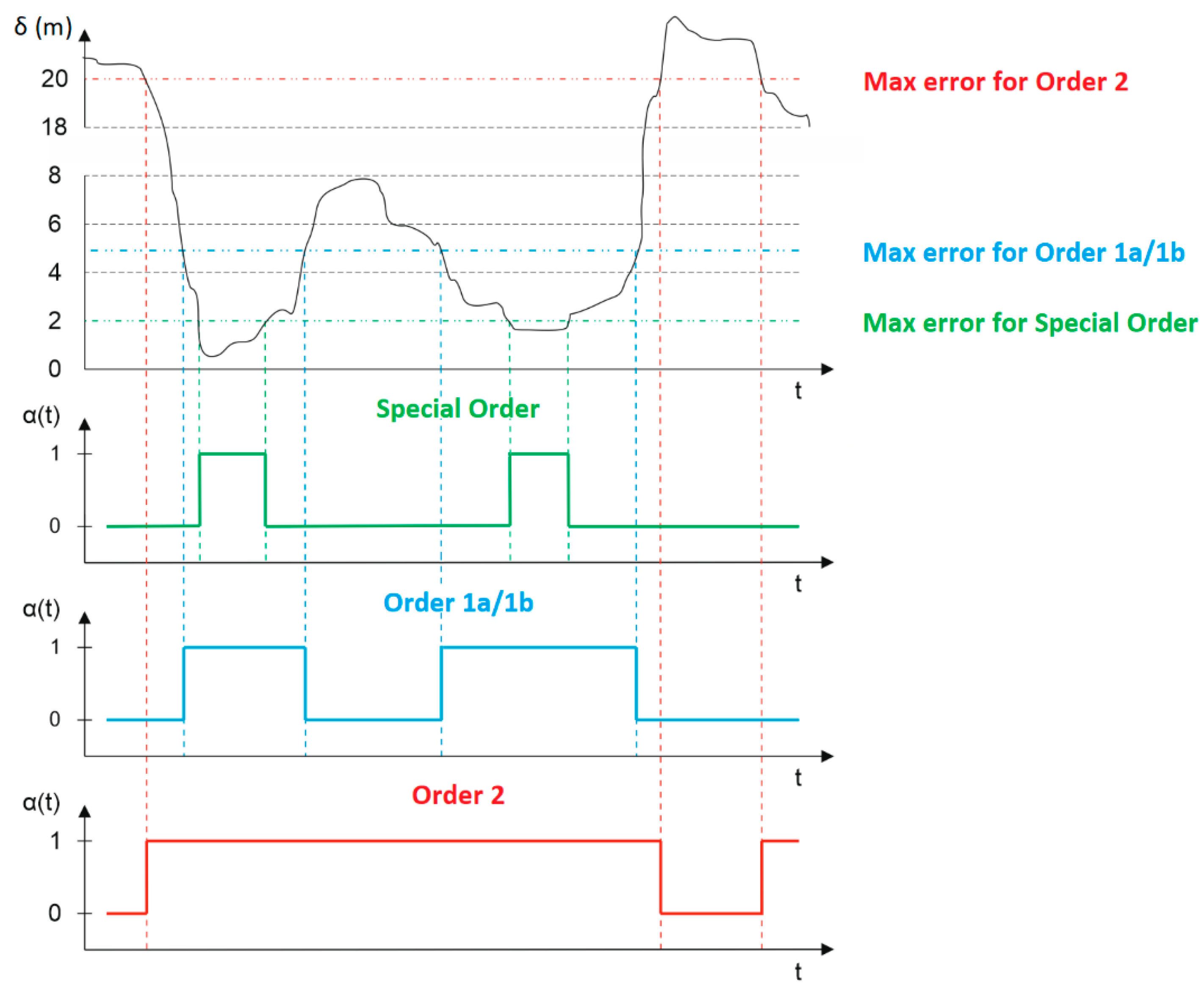
- Exclusive Order—sets down the highest requirements in the field of positioning accuracy. According to this order, hydrographic surveys are carried out on shallow waterbodies for which the under-keel clearance is minimal, and the bottom topography poses a potential hazard to the safety of navigation. Examples of such areas include harbours, berthing areas and critical areas of fairways and channels. The maximum permissible position error is 1 m with a confidence level of 95%;
- Special Order—applies to the waterbodies for which the under-keel clearance is critical. Examples of such areas include berthing areas, harbours and critical areas of fairways and shipping channels. The maximum permissible position error is 1 m with a confidence level of 95%;
- Order 1a—applies to waterbodies with depths of less than 100 m, for which the under-keel clearance is less critical, yet there is a possibility of the occurrence of underwater objects posing a hazard to safe navigation. The maximum permissible position error is 5 m + 5% of depth with a confidence level of 95%;
- Order 1b—applies to waterbodies with depths of less than 100 m, for which the under-keel clearance is not significant for the expected type of navigation. The maximum permissible position error is 5 m + 5% of depth with a confidence level of 95%;
- Order 2—imposes requirements on the positioning systems (and not only) used for hydrographic surveys of waterbodies with depths of more than 100 m, where the general depiction of the bottom is sufficient for the expected type of navigation. The maximum permissible position error is 20 m + 5% of depth with a confidence level of 95%.
2. Materials and Methods
2.1. Measurement Equipment
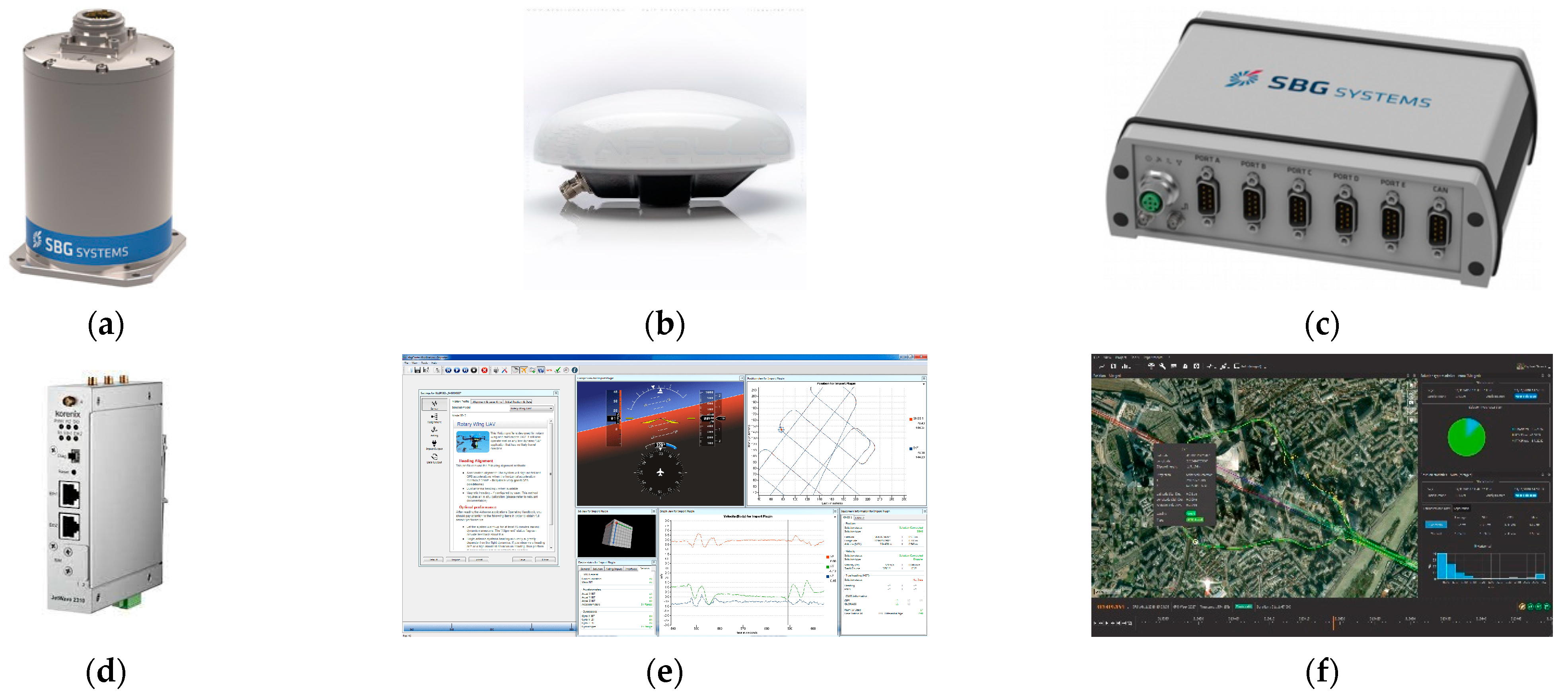
- An Inertial Measurement Unit (IMU) (SBG Systems, Carrières-sur-Seine, France) (Figure 1a), comprised of three accelerometers and three gyroscopes, used to measure accelerations and angular velocities along the pitch, roll and yaw axes of a moving object;
- Two antennas: an AERO GPS and GNSS Survey Antenna AT1675-382 (Apollo Satellite, San Diego, CA, USA) (Figure 1b) used to measure the course of a moving vehicle. They track GPS, GLONASS and Galileo satellites;
- The SplitBox computer system (SBG Systems, Carrières-sur-Seine, France) (Figure 1c) used to acquire and process data recorded in real-time by two GNSS receivers (embedded inside the SplitBox system), an IMU and two external GNSS antennas;
- A modem, enabling the reception of RTK/RTN corrections (Korenix Technology, New Taipei City, Taiwan) (Figure 1d) and providing the positioning accuracy of a 1–2-centimetre Distance Root Mean Square (DRMS) in the horizontal plane and 2–3-centimetre Root Mean Square (RMS) in the vertical plane;
- The sbgCenter software (SBG Systems, Carrières-sur-Seine, France) (Figure 1e) used to set the operation parameters in real-time for the Ekinox2-U system;
- The Qinertia software (SBG Systems, Carrières-sur-Seine, France) (Figure 1f) used to process data recorded by the Ekinox2-U system in the post-processing mode.
- The Ekinox2-U system provides operation in the following two modes:
- ○
- DGPS—this method involves the use of a base station (the so-called reference station), i.e., a receiver positioned at a precisely designated point that determines, on an ongoing basis, differential corrections for all satellites found in the station’s field of view. The second (mobile) receiver must be able to receive these corrections, e.g., via a satellite connection, Very High Frequency (VHF), General Packet Radio Service (GPRS)/Wireless Local Area Network (WLAN), which are transmitted in the Radio Technical Commission for Maritime (RTCM), Compact Measurement Record (CMR) or another format;
- ○
- RTK—this method involves radio transmission of L1 and L2 carrier phase observation data or corrections from a base station of known coordinates to a mobile receiver where a position is determined. Double differencing the measurements and resolving the integer ambiguities provide relative positioning accuracies at the centimetre level.
- The recording frequency for the data on angles, accelerations and position coordinates should be as high as possible. It is recommended that the IMU’s data should be recorded with a maximum frequency of 200 Hz.
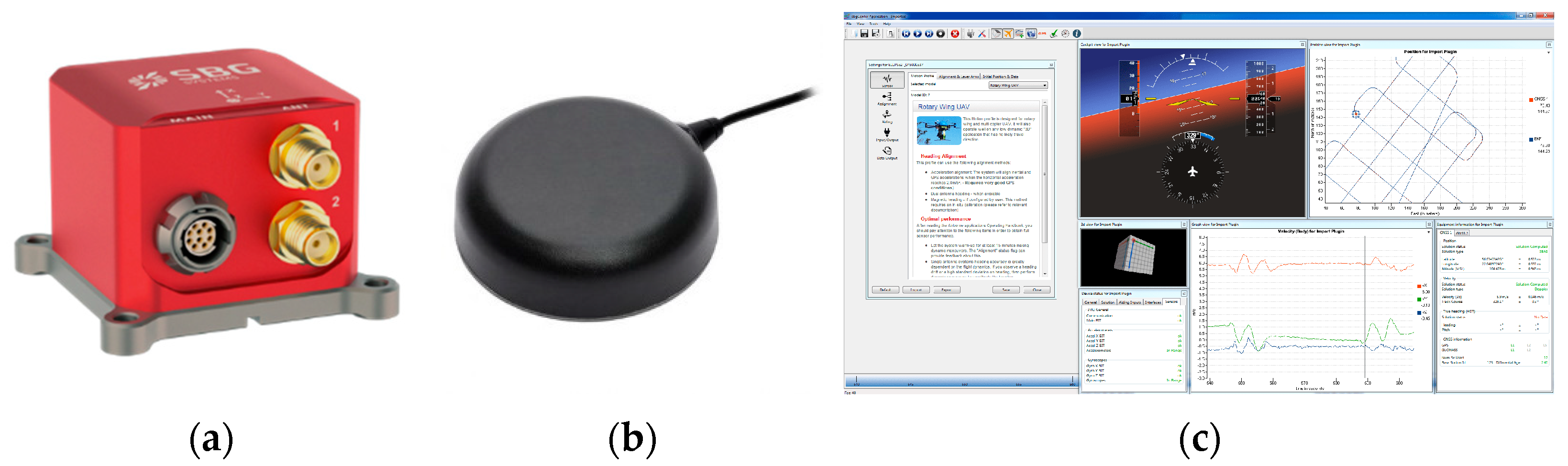
- An IMU (SBG Systems, Carrières-sur-Seine, France) (Figure 2a), comprised of three accelerometers and three gyroscopes, used to measure accelerations and angular velocities along the pitch, roll and yaw axes of a moving object;
- Two TW7972 Triple Band GNSS Antennas with L-band (Tallysman Wireless Inc., Ottawa, Canada) (Figure 2b) used to measure the course of a moving vehicle. They track GPS, GLONASS, BDS and Galileo satellites;
- The sbgCenter software (Figure 2c) used to set the operation parameters in real-time for the Ellipse-D system.
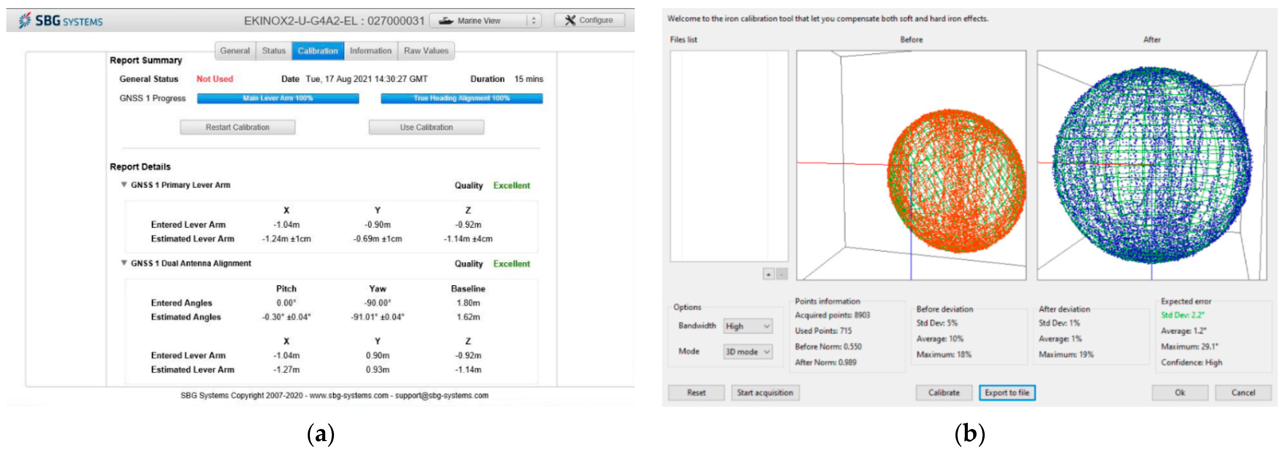
2.2. Configuration and Calibration of GNSS/INS Systems
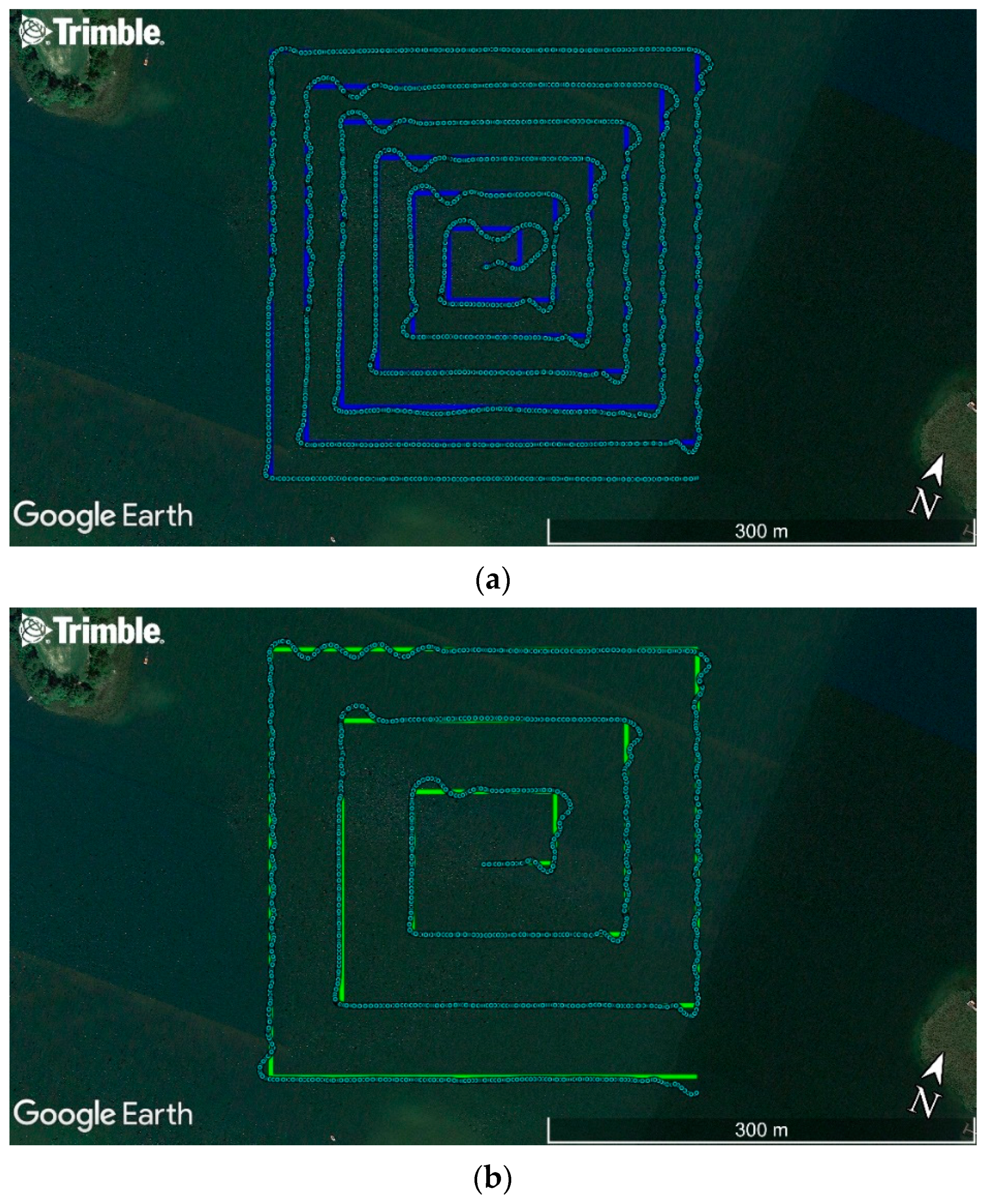
2.3. GNSS/INS Measurements
2.4. GNSS/INS Data Processing
3. Results
4. Discussion
5. Conclusions
Author Contributions
Funding
Institutional Review Board Statement
Informed Consent Statement
Data Availability Statement
Conflicts of Interest
References
- IHO. IHO Standards for Hydrographic Surveys, 6th ed.; Special Publication No. 44; IHO: Monaco, Monaco, 2020. [Google Scholar]
- Li, W.; Liu, G.; Cui, X.; Lu, M. Feature-aided RTK/LiDAR/INS Integrated Positioning System with Parallel Filters in the Ambiguity-position-joint Domain for Urban Environments. Remote Sens. 2021, 13, 2013. [Google Scholar] [CrossRef]
- Won, D.H.; Lee, E.; Heo, M.; Lee, S.-W.; Lee, J.; Kim, J.; Sung, S.; Jae, Y. Selective Integration of GNSS, Vision Sensor, and INS Using Weighted DOP Under GNSS-challenged Environments. IEEE Trans. Instrum. Meas. 2014, 63, 2288–2298. [Google Scholar] [CrossRef]
- Yan, P.; Jiang, J.; Tang, Y.; Zhang, F.; Xie, D.; Wu, J.; Liu, J.; Liu, J. Dynamic Adaptive Low Power Adjustment Scheme for Single-frequency GNSS/MEMS-IMU/Odometer Integrated Navigation in the Complex Urban Environment. Remote Sens. 2021, 13, 3236. [Google Scholar] [CrossRef]
- Broumandan, A.; Lachapelle, G. Spoofing Detection Using GNSS/INS/Odometer Coupling for Vehicular Navigation. Sensors 2018, 18, 1305. [Google Scholar] [CrossRef] [PubMed] [Green Version]
- Vagle, N.; Broumandan, A.; Lachapelle, G. Multi-antenna GNSS and Inertial Sensors/Odometer Coupling for Robust Vehicular Navigation. IEEE Internet Things J. 2018, 5, 4816–4828. [Google Scholar] [CrossRef]
- Yang, L.; Li, Y.; Wu, Y.; Rizos, C. An Enhanced MEMS-INS/GNSS Integrated System with Fault Detection and Exclusion Capability for Land Vehicle Navigation in Urban Areas. GPS Solutions 2014, 18, 593–603. [Google Scholar] [CrossRef]
- Brazeal, R.G.; Wilkinson, B.E.; Benjamin, A.R. Investigating Practical Impacts of Using Single-antenna and Dual-antenna GNSS/INS Sensors in UAS-Lidar Applications. Sensors 2021, 21, 5382. [Google Scholar] [CrossRef] [PubMed]
- Mwenegoha, H.A.; Moore, T.; Pinchin, J.; Jabbal, M. A Model-based Tightly Coupled Architecture for Low-cost Unmanned Aerial Vehicles for Real-time Applications. IEEE Access 2020, 1–20. [Google Scholar] [CrossRef]
- Naus, K.; Szymak, P.; Piskur, P.; Niedziela, M.; Nowak, A. Methodology for the Correction of the Spatial Orientation Angles of the Unmanned Aerial Vehicle Using Real Time GNSS, a Shoreline Image and an Electronic Navigational Chart. Energies 2021, 14, 2810. [Google Scholar] [CrossRef]
- Wang, Q.; Cui, X.; Li, Y.; Ye, F. Performance Enhancement of a USV INS/CNS/DVL Integration Navigation System Based on an Adaptive Information Sharing Factor Federated Filter. Sensors 2017, 17, 239. [Google Scholar] [CrossRef] [PubMed] [Green Version]
- Xia, G.; Wang, G. INS/GNSS Tightly-Coupled Integration Using Quaternion-based AUPF for USV. Sensors 2016, 16, 1215. [Google Scholar] [CrossRef] [Green Version]
- Yan, W.; Zhang, Q.; Zhang, Y.; Wang, A.; Zhao, C. The Validation and Performance Assessment of the Android Smartphone Based GNSS/INS Coupled Navigation System. In Proceedings of the 12th China Satellite Navigation Conference (CSNC 2021), Nanchang, China, 22–25 May 2021. [Google Scholar]
- Li, N.; Guan, L.; Gao, Y.; Du, S.; Wu, M.; Guang, X.; Cong, X. Indoor and Outdoor Low-cost Seamless Integrated Navigation System Based on the Integration of INS/GNSS/LIDAR System. Remote Sens. 2020, 12, 3271. [Google Scholar] [CrossRef]
- Zhuang, Y.; Lan, H.; Li, Y.; El-Sheimy, N. PDR/INS/WiFi Integration Based on Handheld Devices for Indoor Pedestrian Navigation. Micromachines 2015, 6, 793–812. [Google Scholar] [CrossRef] [Green Version]
- Jing, S.; Zhan, X.; Liu, B.; Chen, M. Weak and Dynamic GNSS Signal Tracking Strategies for Flight Missions in the Space Service Volume. Sensors 2016, 16, 1412. [Google Scholar] [CrossRef] [PubMed] [Green Version]
- Barzaghi, R.; Carrion, D.; Pepe, M.; Prezioso, G. Computing the Deflection of the Vertical for Improving Aerial Surveys: A Comparison between EGM2008 and ITALGEO05 Estimates. Sensors 2016, 16, 1168. [Google Scholar] [CrossRef] [PubMed] [Green Version]
- Pytka, J.; Budzyński, P.; Józwik, J.; Michałowska, J.; Tofil, A.; Łyszczyk, T.; Błażejczak, D. Application of GNSS/INS and an Optical Sensor for Determining Airplane Takeoff and Landing Performance on a Grassy Airfield. Sensors 2019, 19, 5492. [Google Scholar] [CrossRef] [PubMed] [Green Version]
- Qian, C.; Liu, H.; Tang, J.; Chen, Y.; Kaartinen, H.; Kukko, A.; Zhu, L.; Liang, X.; Chen, L.; Hyyppä, J. An Integrated GNSS/INS/LiDAR-SLAM Positioning Method for Highly Accurate Forest Stem Mapping. Remote Sens. 2017, 9, 3. [Google Scholar] [CrossRef] [Green Version]
- El-Diasty, M. Development of Real-time PPP-based GPS/INS Integration System Using IGS Real-time Service for Hydrographic Surveys. J. Surv. Eng. 2016, 142, 05015005. [Google Scholar] [CrossRef]
- El-Diasty, M. Evaluation of KSACORS-based Network GNSS-INS Integrated System for Saudi Coastal Hydrographic Surveys. Geomat. Nat. Hazards Risk 2020, 11, 1426–1446. [Google Scholar] [CrossRef]
- Scheider, A.; Wirth, H.; Breitenfeld, M.; Schwieger, V. HydrOs—An Integrated Hydrographic Positioning System for Surveying Vessels. In Proceedings of the XXV FIG Congress 2014, Kuala Lumpur, Malaysia, 16–21 June 2014. [Google Scholar]
- Bedkowski, J.; Nowak, H.; Kubiak, B.; Studzinski, W.; Janeczek, M.; Karas, S.; Kopaczewski, A.; Makosiej, P.; Koszuk, J.; Pec, M.; et al. A Novel Approach to Global Positioning System Accuracy Assessment, Verified on LiDAR Alignment of One Million Kilometers at a Continent Scale, as a Foundation for Autonomous DRIVING Safety Analysis. Sensors 2021, 21, 5691. [Google Scholar] [CrossRef]
- Elsheikh, M.; Abdelfatah, W.; Noureldin, A.; Iqbal, U.; Korenberg, M. Low-cost Real-time PPP/INS Integration for Automated Land Vehicles. Sensors 2019, 19, 4896. [Google Scholar] [CrossRef] [Green Version]
- Zhu, F.; Shen, Y.; Wang, Y.; Jia, J.; Zhang, X. Fusing GNSS/INS/Vision with a Priori Feature Map for High-precision and Continuous Navigation. IEEE Sens. J. 2021, 21, 23370–23381. [Google Scholar] [CrossRef]
- Sun, Z.; Tang, K.; Wang, X.; Wu, M.; Guo, Y. High-speed Train Tunnel Navigation Method Based on Integrated MIMU/ODO/MC Navigation. Appl. Sci. 2021, 11, 3680. [Google Scholar] [CrossRef]
- Sun, Z.; Tang, K.; Wu, M.; Guo, Y.; Wang, X. High-speed Train Positioning Method Based on Motion Constraints Suppressing INS Error in Tunnel. J. Northwest. Polytech. Univ. 2021, 39, 624–632. [Google Scholar] [CrossRef]
- Chen, K.; Chang, G.; Chen, C. GINav: A MATLAB-based Software for the Data Processing and Analysis of a GNSS/INS Integrated Navigation System. GPS Solutions 2021, 25, 108. [Google Scholar] [CrossRef]
- Du, S.; Zhang, S.; Gan, X. A Hybrid Fusion Strategy for the Land Vehicle Navigation Using MEMS INS, Odometer and GNSS. IEEE Access 2020, 8, 152512–152522. [Google Scholar] [CrossRef]
- Elmezayen, A.; El-Rabbany, A. Ultra-low-cost Tightly Coupled Triple-constellation GNSS PPP/MEMS-based INS Integration for Land Vehicular Applications. Geomatics 2021, 1, 258–286. [Google Scholar] [CrossRef]
- Dong, P.; Cheng, J.; Liu, L. A Novel Anti-jamming Technique for INS/GNSS Integration Based on Black Box Variational Inference. Appl. Sci. 2021, 11, 3664. [Google Scholar] [CrossRef]
- Kujur, B.; Khanafseh, S.; Pervan, B. Detecting GNSS Spoofing of ADS-B Equipped Aircraft Using INS. In Proceedings of the 2020 IEEE/ION Position, Location and Navigation Symposium (PLANS 2020), Portland, OR, USA, 20–23 April 2020. [Google Scholar]
- Specht, C.; Specht, M.; Dąbrowski, P. Comparative Analysis of Active Geodetic Networks in Poland. In Proceedings of the 17th International Multidisciplinary Scientific GeoConference (SGEM 2017), Albena, Bulgaria, 27 June–6 July 2017. [Google Scholar]
- Mora, O.E.; Langford, M.; Mislang, R.; Josenhans, R.; Jorge Chen, J. Precision Performance Evaluation of RTK and RTN Solutions: A Case Study. J. Spat. Sci. 2020, 1–14. [Google Scholar] [CrossRef]
- Bakuła, M. Study of Reliable Rapid and Ultrarapid Static GNSS Surveying for Determination of the Coordinates of Control Points in Obstructed Conditions. J. Surv. Eng. 2013, 139, 188–193. [Google Scholar] [CrossRef]
- Bogusz, J.; Figurski, M.; Kontny, B.; Grzempowski, P. Horizontal Velocity Field Derived from EPN and ASG-EUPOS Satellite Data on the Example of South-western Part of Poland. Acta Geodyn. Geomater. 2012, 9, 349–357. [Google Scholar]
- Stępniak, K.; Baryła, R.; Wielgosz, P.; Kurpiński, G. Optimal Data Processing Strategy in Precise GPS Levelling Networks. Acta Geodyn. Geomater. 2013, 10, 443–452. [Google Scholar] [CrossRef] [Green Version]
- Ćwiąkała, P.; Gabryszuk, J.; Krawczyk, K.; Krzyżek, R.; Leń, P.; Oleniacz, G.; Puchniach, E.; Siejka, Z.; Wójcik-Leń, J. GNSS Technology and Its Application in Setting out Surveys and Monitoring; Rzeszów School of Engineering and Economics Publishing House: Rzeszów, Poland, 2015. (In Polish) [Google Scholar]
- Przestrzelski, P.; Bakuła, M. Performance of Real-time Network Code DGPS Services of ASG-EUPOS in North-Eastern Poland. Tech. Sci. 2014, 17, 191–207. [Google Scholar]
- Specht, C.; Rudnicki, J. A Method for the Assessing of Reliability Characteristics Relevant to an Assumed Position-fixing Accuracy in Navigational Positioning Systems. Pol. Marit. Res. 2016, 23, 20–27. [Google Scholar] [CrossRef] [Green Version]
- Visconti, P.; Iaia, F.; De Fazio, R.; Giannoccaro, N.I. A Stake-out Prototype System Based on GNSS-RTK Technology for Implementing Accurate Vehicle Reliability and Performance Tests. Energies 2021, 14, 4885. [Google Scholar] [CrossRef]
- Bakuła, M.; Pelc-Mieczkowska, R.; Walawski, M. Reliable and Redundant RTK Positioning for Applications in Hard Observational Conditions. Artif. Satell. 2012, 47, 23–33. [Google Scholar] [CrossRef]
- Janos, D.; Kuras, P. Evaluation of Low-cost GNSS Receiver under Demanding Conditions in RTK Network Mode. Sensors 2021, 21, 5552. [Google Scholar] [CrossRef] [PubMed]
- IALA. IALA Recommendation R-121 on the Performance and Monitoring of DGNSS Services in the Frequency Band 283.5–325 kHz, 2.0 ed.; IALA: Saint-Germain-en-Laye, France, 2015. [Google Scholar]
- Specht, C.; Weintrit, A.; Specht, M. A History of Maritime Radio-navigation Positioning Systems Used in Poland. J. Navig. 2016, 69, 468–480. [Google Scholar] [CrossRef] [Green Version]
- Dziewicki, M.; Specht, C. Position Accuracy Evaluation of the Modernized Polish DGPS. Pol. Marit. Res. 2009, 16, 57–61. [Google Scholar] [CrossRef]
- Kim, J.; Song, J.; No, H.; Han, D.; Kim, D.; Park, B.; Kee, C. Accuracy Improvement of DGPS for Low-cost Single-frequency Receiver Using Modified Flachen Korrektur Parameter Correction. ISPRS Int. J. Geo-Inf. 2017, 6, 222. [Google Scholar] [CrossRef] [Green Version]
- Lubis, M.Z.; Anggraini, K.; Kausarian, H.; Pujiyati, S. Review: Marine Seismic and Side-scan Sonar Investigations for Seabed Identification with Sonar System. J. Geosci. Eng. Environ. Technol. 2017, 2, 166–170. [Google Scholar] [CrossRef] [Green Version]
- Ratheesh, R.; Ritesh, A.; Remya, P.G.; Nagakumar, K.C.V.; Demudu, G.; Rajawat, A.S.; Nair, B.; Nageswara Rao, K. Modelling Coastal Erosion: A Case Study of Yarada Beach Near Visakhapatnam, East Coast of India. Ocean. Coast. Manag. 2018, 156, 239–248. [Google Scholar]
- Ward, R.D.; Burnside, N.G.; Joyce, C.B.; Sepp, K.; Teasdale, P.A. Improved Modelling of the Impacts of Sea Level Rise on Coastal Wetland Plant Communities. Hydrobiologia 2016, 774, 203–216. [Google Scholar] [CrossRef] [Green Version]
- Honarmand, M.; Shahriari, H. Geological Mapping Using Drone-based Photogrammetry: An Application for Exploration of Vein-type Cu Mineralization. Minerals 2021, 11, 585. [Google Scholar] [CrossRef]
- Ji, S.; Gao, Z.; Wang, W. M-DGPS: Mobile Devices Supported Differential Global Positioning System Algorithm. Arab. J. Geosci. 2015, 8, 6667–6675. [Google Scholar] [CrossRef]
- Yoon, D.; Kee, C.; Seo, J.; Park, B. Position Accuracy Improvement by Implementing the DGNSS-CP Algorithm in Smartphones. Sensors 2016, 16, 910. [Google Scholar] [CrossRef] [PubMed] [Green Version]
- Krasuski, K.; Popielarczyk, D.; Ciećko, A.; Ćwiklak, J. A New Strategy for Improving the Accuracy of Aircraft Positioning Using DGPS Technique in Aerial Navigation. Energies 2021, 14, 4431. [Google Scholar] [CrossRef]
- Yoon, H.; Seok, H.; Lim, C.; Park, B. An Online SBAS Service to Improve Drone Navigation Performance in High-elevation Masked Areas. Sensors 2020, 20, 3047. [Google Scholar] [CrossRef]
- Chen, H.; Moan, T.; Verhoeven, H. Effect of DGPS Failures on Dynamic Positioning of Mobile Drilling Units in the North Sea. Accid. Anal. Prev. 2009, 41, 1164–1171. [Google Scholar] [CrossRef]
- Kim, Y.W. DGPS Service Analysis in the Korean Coastal Ferry Route. J. Korea Inst. Inf. Commun. Eng. 2014, 18, 2073–2078. [Google Scholar] [CrossRef] [Green Version]
- Moore, T.; Hill, C.; Monteiro, L. Is DGPS Still a Good Option for Mariners? J. Navig. 2001, 54, 437–446. [Google Scholar] [CrossRef]
- Ibrahim, P.O.; Sternberg, H. Bathymetric Survey for Enhancing the Volumetric Capacity of Tagwai Dam in Nigeria via Leapfrogging Approach. Geomatics 2021, 1, 246–257. [Google Scholar] [CrossRef]
- Bini, M.; Casarosa, N.; Luppichini, M. Exploring the Relationship between River Discharge and Coastal Erosion: An Integrated Approach Applied to the Pisa Coastal Plain (Italy). Remote Sens. 2021, 13, 226. [Google Scholar] [CrossRef]
- Frati, G.; Launeau, P.; Robin, M.; Giraud, M.; Juigner, M.; Debaine, F.; Michon, C. Coastal Sand Dunes Monitoring by Low Vegetation Cover Classification and Digital Elevation Model Improvement Using Synchronized Hyperspectral and Full-waveform LiDAR Remote Sensing. Remote Sens. 2021, 13, 29. [Google Scholar] [CrossRef]
- Rathour, S.S.; Boyali, A.; Zheming, L.; Mita, S.; John, V. A Map-based Lateral and Longitudinal DGPS/DR Bias Estimation Method for Autonomous Driving. Int. J. Mach. Learn. Comput. 2017, 7, 67–71. [Google Scholar] [CrossRef]
- Ssebazza, L.; Pan, Y.J. DGPS-based Localization and Path Following Approach for Outdoor Wheeled Mobile Robots. Int. J. Robot. Autom. 2015, 30, 13–25. [Google Scholar] [CrossRef]
- Vetrella, A.R.; Fasano, G.; Accardo, D.; Moccia, A. Differential GNSS and Vision-based Tracking to Improve Navigation Performance in Cooperative Multi-UAV Systems. Sensors 2016, 16, 2164. [Google Scholar] [CrossRef] [PubMed]
- Liu, J.; Wang, L.; Teng, F.; Li, D.; Wang, X.; Cao, H. Crop Area Ground Sample Survey Using Google Earth Image-aided. Trans. Chin. Soc. Agric. Eng. 2015, 31, 149–154. [Google Scholar]
- Muhammad, S.; Tian, L. Hunza, Gilgit and Astore Valley Glacier Elevation Changes During 2003 to 2014 Using ICESat and DGPS Data. In Proceedings of the International Symposium on Glaciology in High-mountain Asia, Kathmandu, Nepal, 1–6 March 2015. [Google Scholar]
- Galan-Martin, D.; Marchamalo-Sacristan, M.; Martinez-Marin, R.; Sanchez-Sobrino, J.A. Geomatics Applied to Dam Safety DGPS Real Time Monitoring. Int. J. Civ. Eng. 2013, 11, 134–141. [Google Scholar]
- Malinowski, M. Precise Point Positioning (PPP) Accuracy Using Online Web Services. J. Civil. Eng. Environ. Archit. 2017, 64, 297–313. [Google Scholar]
- Zhang, B.; Chen, Y.; Yuan, Y. PPP-RTK Based on Undifferenced and Uncombined Observations: Theoretical and Practical Aspects. J. Geod. 2019, 93, 1011–1024. [Google Scholar] [CrossRef]
- Zhang, B.; Hou, P.; Zha, J.; Liu, T. Integer-estimable FDMA Model as an Enabler of GLONASS PPP-RTK. J. Geod. 2021, 95, 91. [Google Scholar] [CrossRef]
- Akpınar, B.; Aykut, N.O. Determining the Coordinates of Control Points in Hydrographic Surveying by the Precise Point Positioning Method. J. Navig. 2017, 70, 1241–1252. [Google Scholar] [CrossRef]
- Erol, S.; Alkan, R.M.; Ozulu, İ.M.; İlçi, V. Performance Analysis of Real-time and Post-mission Kinematic Precise Point Positioning in Marine Environments. Geod. Geodyn. 2020, 11, 401–410. [Google Scholar] [CrossRef]
- Seonghyeon, Y.; Hungkyu, L.; Yunsoo, C.; Geonwoo, H. Potential Accuracy of GNSS PPP- and PPK-derived Heights for Ellipsoidally Referenced Hydrographic Surveys: Experimental Assessment and Results. J. Position. Navig. Timing 2017, 6, 211–221. [Google Scholar]
- Specht, M.; Stateczny, A.; Specht, C.; Widźgowski, S.; Lewicka, O.; Wiśniewska, M. Concept of an Innovative Autonomous Unmanned System for Bathymetric Monitoring of Shallow Waterbodies (INNOBAT System). Energies 2021, 14, 5370. [Google Scholar] [CrossRef]
- SBG Systems. Ekinox Series. Available online: https://www.sbg-systems.com/products/ekinox-series/ (accessed on 5 November 2021).
- SBG Systems. Ellipse Series. Available online: https://www.sbg-systems.com/products/ellipse-series/ (accessed on 5 November 2021).
- Stateczny, A.; Kazimierski, W.; Burdziakowski, P.; Motyl, W.; Wisniewska, M. Shore Construction Detection by Automotive Radar for the Needs of Autonomous Surface Vehicle Navigation. ISPRS Int. J. Geo-Inf. 2019, 8, 80. [Google Scholar] [CrossRef] [Green Version]
- Specht, M.; Specht, C.; Lasota, H.; Cywiński, P. Assessment of the Steering Precision of a Hydrographic Unmanned Surface Vessel (USV) along Sounding Profiles Using a Low-cost Multi-Global Navigation Satellite System (GNSS) Receiver Supported Autopilot. Sensors 2019, 19, 3939. [Google Scholar] [CrossRef] [Green Version]
- Specht, M.; Specht, C.; Dąbrowski, P.; Czaplewski, K.; Smolarek, L.; Lewicka, O. Road Tests of the Positioning Accuracy of INS/GNSS Systems Based on MEMS Technology for Navigating Railway Vehicles. Energies 2020, 13, 4463. [Google Scholar] [CrossRef]
- Szot, T.; Specht, C.; Specht, M.; Dabrowski, P.S. Comparative Analysis of Positioning Accuracy of Samsung Galaxy Smartphones in Stationary Measurements. PLoS ONE 2019, 14, e0215562. [Google Scholar] [CrossRef] [PubMed]
- Specht, M. Method of Evaluating the Positioning System Capability for Complying with the Minimum Accuracy Requirements for the International Hydrographic Organization Orders. Sensors 2019, 19, 3860. [Google Scholar] [CrossRef] [PubMed] [Green Version]
- Specht, C. Availability, Reliability and Continuity Model of Differential GPS Transmission. Annu. Navig. 2003, 5, 1–85. [Google Scholar]
- Specht, C.; Pawelski, J.; Smolarek, L.; Specht, M.; Dąbrowski, P. Assessment of the Positioning Accuracy of DGPS and EGNOS Systems in the Bay of Gdansk Using Maritime Dynamic Measurements. J. Navig. 2019, 72, 575–587. [Google Scholar] [CrossRef] [Green Version]


| Measurement Error | Time That Has Elapsed Since the GNSS Signal Was Not Available | |||||||
|---|---|---|---|---|---|---|---|---|
| 0 s | 10 s | |||||||
| Ellipse-D | Ekinox2-U | Ellipse-D | Ekinox2-U | |||||
| DGPS | RTK | DGPS | RTK | DGPS | RTK | DGPS | RTK | |
| σ2D (m) | 1.2 | 0.01 | 1.2 | 0.01 | 3 | 1 | 2 | 0.35 |
| σH (m) | 1.5 | 0.02 | 2 | 0.02 | 3.5 | 1 | 3 | 0.15 |
| σβ, σα (°) | 0.1 | 0.05 | 0.05 | 0.05 | 0.1 | 0.05 | 0.1 | 0.1 |
| σδ (°) | 0.8 | 0.2 | 0.1 | 0.05 | 0.8 | 0.2 | 0.15 | 0.1 |
| Statistics of Position Error | GNSS System | Type of Registered Data | |
|---|---|---|---|
| Ekinox2-U | Ellipse-D | ||
| Number of measurements | 4000 | 4000 |  Ekinox2-U  Ellipse-D |
| RMS(ϕ) | 0.093 m | 0.732 m | |
| RMS(λ) | 0.092 m | 0.732 m | |
| RMS(h) | 0.062 m | 0.558 m | |
| DRMS(2D) | 0.130 m | 1.035 m | |
| 2DRMS(2D) | 0.261 m | 2.069 m | |
| DRMS(3D) | 0.144 m | 1.176 m | |
| CEP(2D) | 0.031 m | 1.005 m | |
| R68(2D) | 0.032 m | 1.013 m | |
| R95(2D) | 0.383 m | 1.036 m | |
| SEP(3D) | 0.037 m | 1.146 m | |
| R68(3D) | 0.037 m | 1.157 m | |
| R95(3D) | 0.418 m | 1.193 m | |
| Statistics of Position Error | GNSS System | Type of Registered Data | |
|---|---|---|---|
| Ekinox2-U | Ellipse-D | ||
| Number of measurements | 2310 | 2310 |  Ekinox2-U Ellipse-D |
| RMS(ϕ) | 0.023 m | 0.864 m | |
| RMS(λ) | 0.022 m | 0.865 m | |
| RMS(h) | 0.019 m | 0.582 m | |
| DRMS(2D) | 0.032 m | 1.222 m | |
| 2DRMS(2D) | 0.064 m | 2.444 m | |
| DRMS(3D) | 0.037 m | 1.353 m | |
| CEP(2D) | 0.032 m | 1.022 m | |
| R68(2D) | 0.032 m | 1.032 m | |
| R95(2D) | 0.034 m | 1.065 m | |
| SEP(3D) | 0.037 m | 1.164 m | |
| R68(3D) | 0.037 m | 1.180 m | |
| R95(3D) | 0.039 m | 1.230 m | |
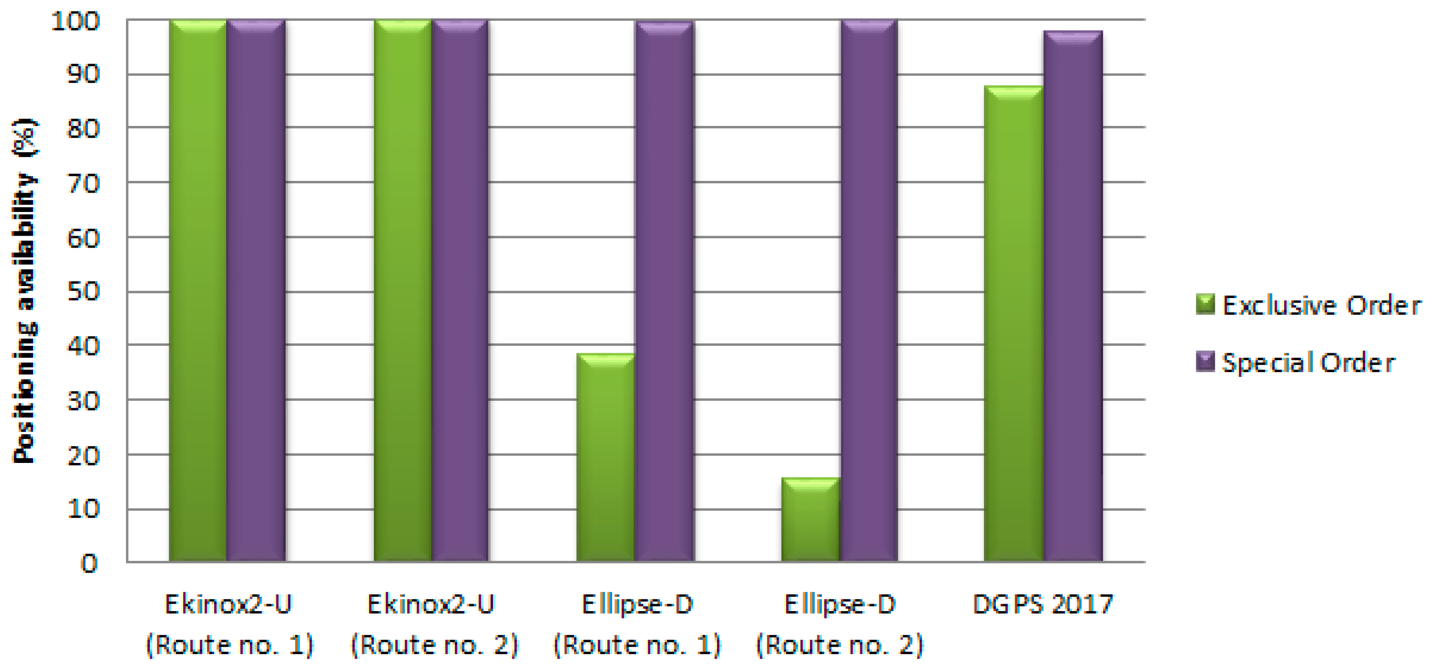
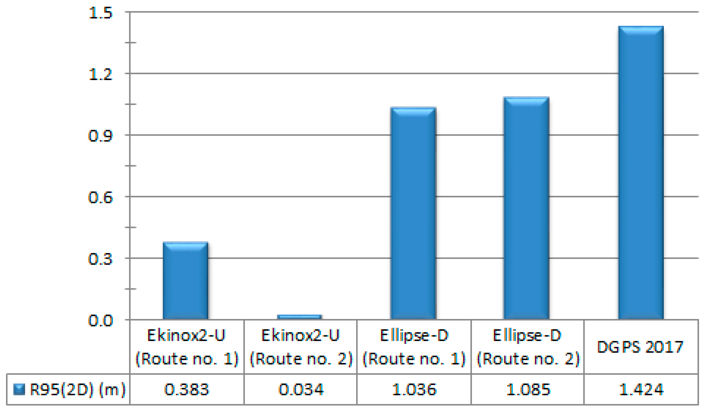
| Positioning System | Positioning Availability (%) | Positioning Accuracy (m) | |||
|---|---|---|---|---|---|
| Exclusive Order | Special Order | 1a/1b Orders | Order 2 | R95(2D) | |
| Ekinox2-U (Route no. 1) | 100 | 100 | 100 | 100 | 0.383 |
| Ekinox2-U (Route no. 2) | 100 | 100 | 100 | 100 | 0.034 |
| Ellipse-D (Route no. 1) | 38.48 | 99.55 | 100 | 100 | 1.036 |
| Ellipse-D (Route no. 2) | 15.54 | 100 | 100 | 100 | 1.085 |
| DGPS 2017 | 87.57 | 98.09 | 100 | 100 | 1.424 |
Publisher’s Note: MDPI stays neutral with regard to jurisdictional claims in published maps and institutional affiliations. |
© 2021 by the authors. Licensee MDPI, Basel, Switzerland. This article is an open access article distributed under the terms and conditions of the Creative Commons Attribution (CC BY) license (https://creativecommons.org/licenses/by/4.0/).
Share and Cite
Stateczny, A.; Specht, C.; Specht, M.; Brčić, D.; Jugović, A.; Widźgowski, S.; Wiśniewska, M.; Lewicka, O. Study on the Positioning Accuracy of GNSS/INS Systems Supported by DGPS and RTK Receivers for Hydrographic Surveys. Energies 2021, 14, 7413. https://doi.org/10.3390/en14217413
Stateczny A, Specht C, Specht M, Brčić D, Jugović A, Widźgowski S, Wiśniewska M, Lewicka O. Study on the Positioning Accuracy of GNSS/INS Systems Supported by DGPS and RTK Receivers for Hydrographic Surveys. Energies. 2021; 14(21):7413. https://doi.org/10.3390/en14217413
Chicago/Turabian StyleStateczny, Andrzej, Cezary Specht, Mariusz Specht, David Brčić, Alen Jugović, Szymon Widźgowski, Marta Wiśniewska, and Oktawia Lewicka. 2021. "Study on the Positioning Accuracy of GNSS/INS Systems Supported by DGPS and RTK Receivers for Hydrographic Surveys" Energies 14, no. 21: 7413. https://doi.org/10.3390/en14217413