In order to model the proposed MPPT fault reduction method, variable speed wind power generation systems, generator speed determination, and MPPT control must be identified to create a mathematical model. Compared to a fixed-speed wind turbine (FSWT), a VSWT can operate at a broader range of wind speeds. Also, VSWTs can generate 10 to 15 percent more energy than installed FSWTs and have less stress on mechanical components, especially blades and shafts, which results in less power fluctuation [
28]. Since the wind velocity could change every moment, the MPPT method should track the small oscillations of generator speed and maximum power points. PMSGs and doubly fed induction generators (DFIGs) are typical VSWTs used for wind turbine configurations. Although DFIGs are more broadly used because of their ability to work at a more extensive speed range, the PMSG has such advantages as:
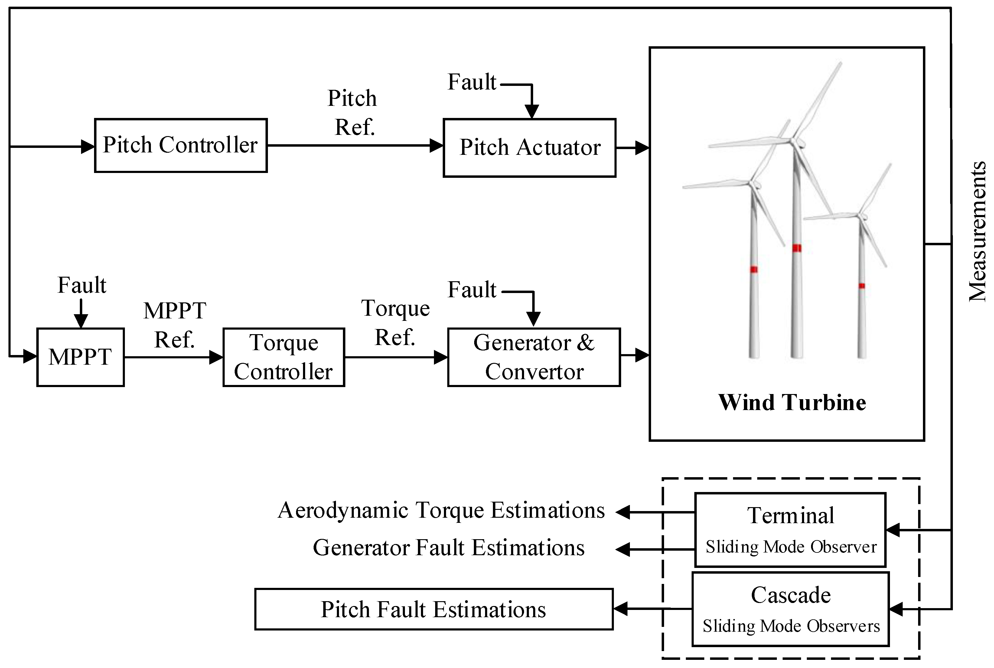
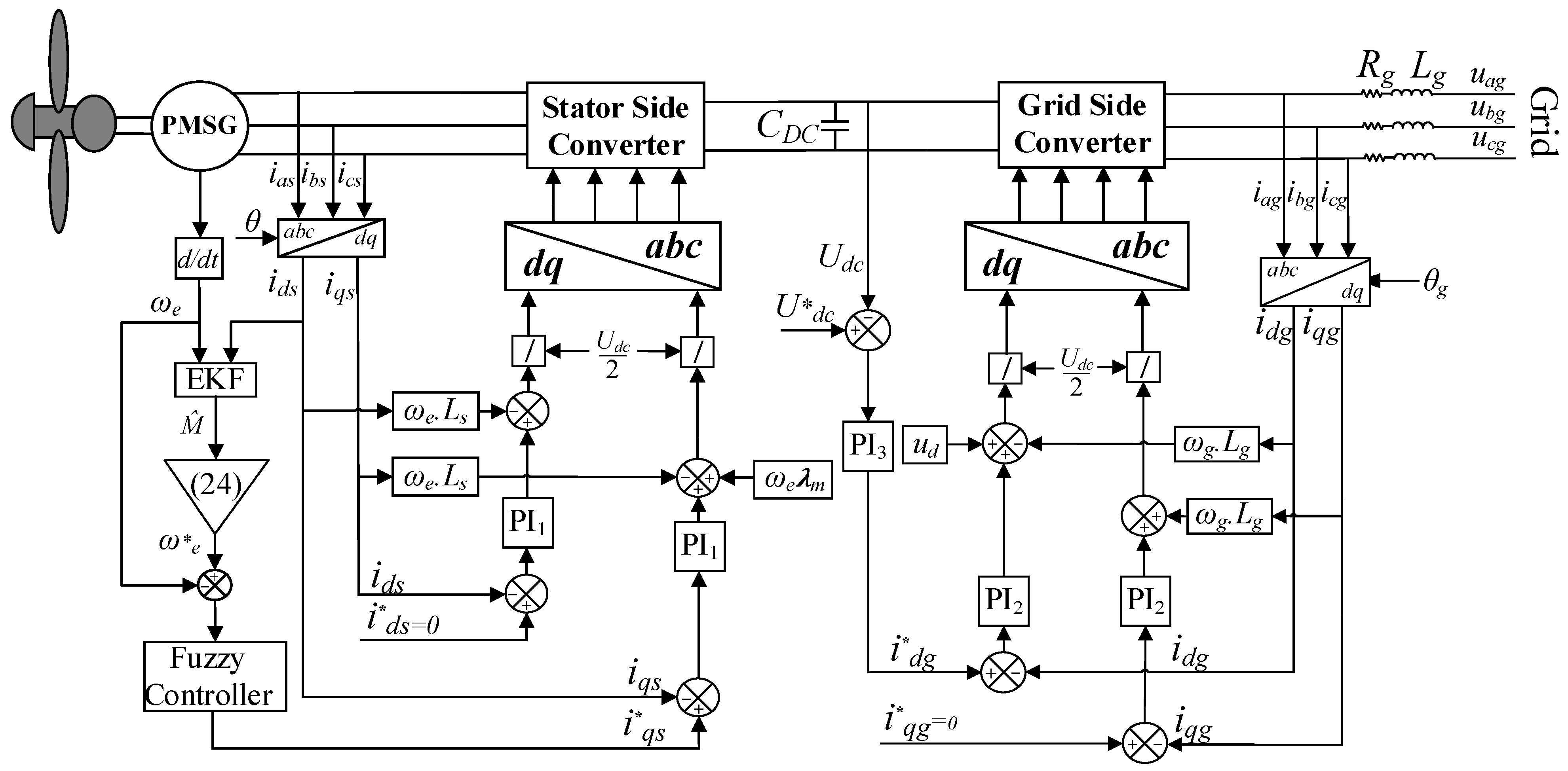
A typical PMSG configuration consists of blades, a generator, a control system, and power electronic converters. The generated electricity has variable frequency and voltage that cannot be directly injected into the grid. The generator is connected to a three-phase rectifier called a stator side converter (SSC), which rectifies the generator current to charge the DC-link capacitor and has primary duties consisting of MPPT, active and reactive power control, and DC-link voltage control [
18]. The DC-link voltage feeds a three-phase inverter, called a grid side converter (GSC), connected to the grid through a transformer.
Figure 1 shows the general wind turbine PMSG system with its control scheme.
One of the most common forms of wind turbine faults is the MPPT fault, which occurs during the small oscillations of wind speed. In other words, the uncertainty of variable parameters, such as wind speed and air density, could make the reference signal of the generator speed inaccurate, leading to the tracking of a wrong signal by the MPPT. The primary goal of this study is to minimize the MPPT fault of the PMSG-based wind turbine, especially during the small oscillations of the wind speed.
2.2. Parameter Estimation
In this section, an estimation and control strategy for unpredictable parameters of the PMSG is introduced. First, the reference signal of generator speed is determined by estimating uncertain parameters through the EKF. Then, using the reference speed, the FLC is employed to design the q-component reference current of the stator.
Equations (1) and (2) show that the stator current components are not only affected by the
and
voltages, but also by the
,
, and
voltages. These voltages are rotor speed functions and will increase substantially as the generator is operating at high speed. Under these conditions, the voltage components will affect the output torque of the current, and the output torque will be inaccurate. Therefore
and
determine the EKF model. For wind turbines, wind power can be expressed as Equation (17) [
34].
where
is the air density,
is the rotor swept area, and
is the wind velocity. The mechanical power of the wind turbine extracted from the wind power is given as Equation (18) [
34].
where
is called the performance coefficient and is a function of the pitch angle (
) and tip speed ratio
. The tip speed ratio can be defined as Equation (19) [
34].
where
is the rotor radius, and
is the blades’ angular velocity. A typical wind turbine performance coefficient example is specified as Equations (20) and (21) [
34].
By replacing Equation (20) in Equation (21), the following extensive model can be derived:
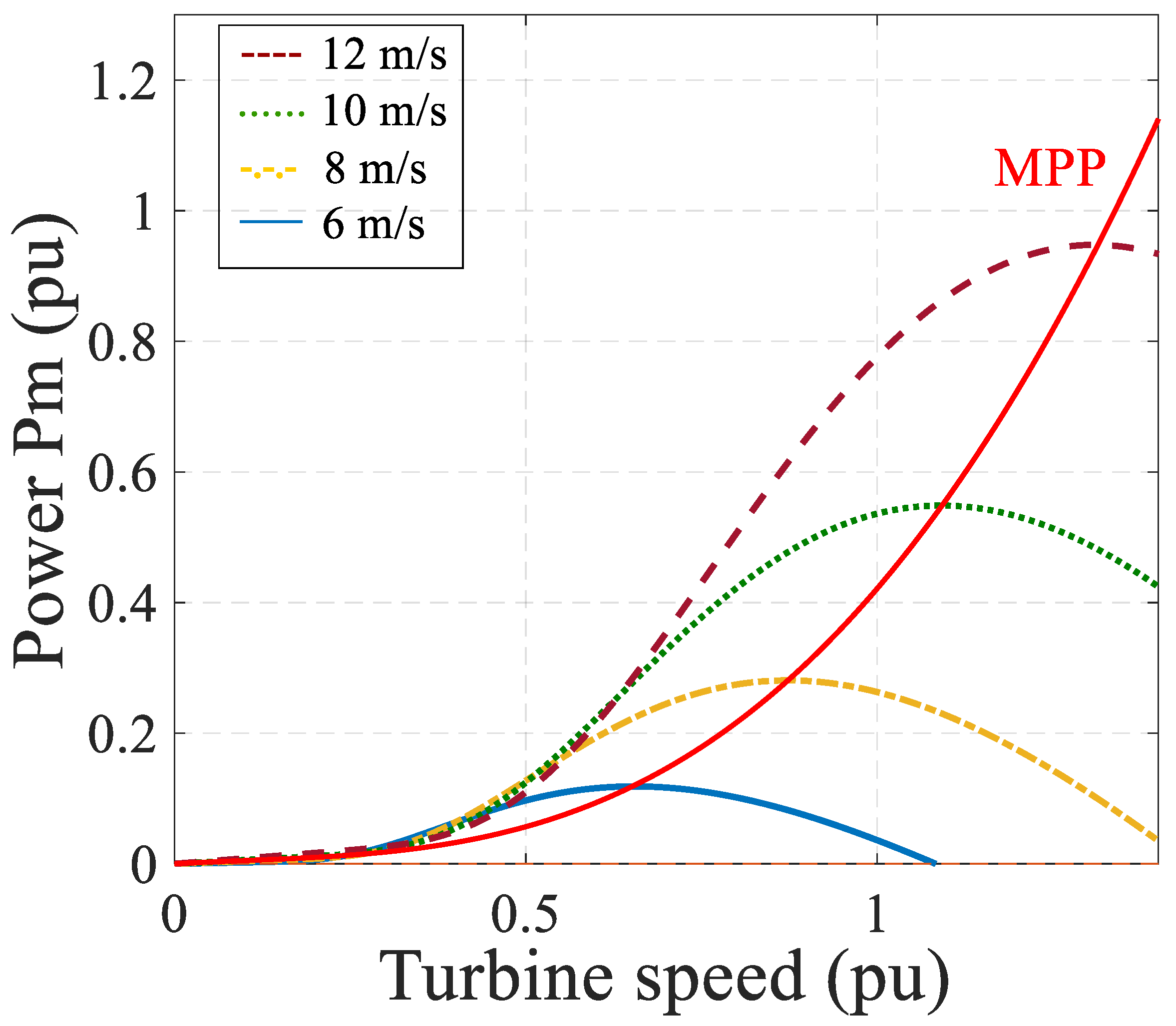
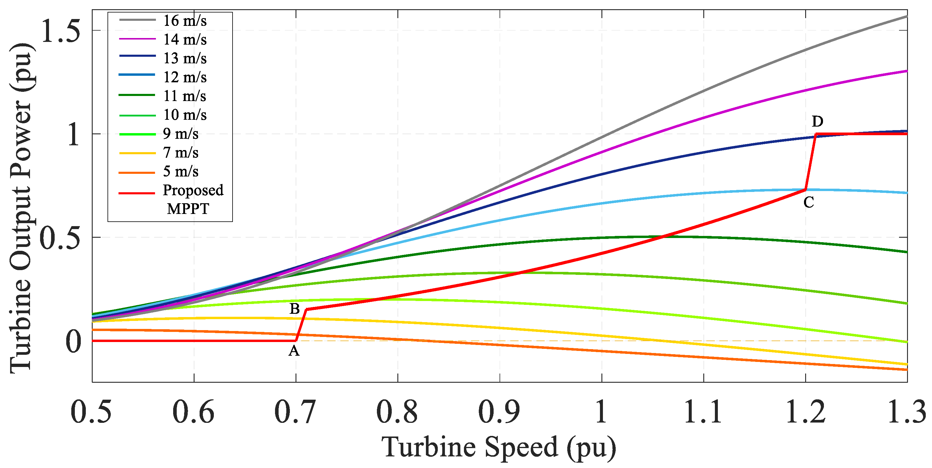
Generally, for small grid-connected wind turbines with a low capacity (less than 10 kW),
will be constant. Therefore, the performance coefficient only depends on
. The
curves at different wind speeds are depicted in
Figure 4.
Figure 4 shows that at maximum power points at different wind speeds, the Equation (23) exists.
This relationship is shown in
Figure 4 with the red curve. Also, to calculate the turbine torque, Equations (24) and (25) can be presented as follows:
By replacing Equations (18) and (22) in Equation (24), the wind turbine torque components can be expressed as Equations (26) and (27).
Also, the wind turbine torque can be expressed as Equation (28):
where
is the torque constant, and
i is the stator current. By replacing Equations (27) and (28) in Equation (25), Equation (29) can be written as follows:
By dividing both sides of the Equation (29) on
, the final equation can be presented as Equation (30).
where the parameters
(wind speed),
(air density), and
(torque constant) are uncertain parameters. These parameters affect the MPPT’s implementation of wind turbine and generator output power. They could decrease the efficiency of the wind turbine, especially during small oscillations of the wind speed. To estimate these parameters, it is assumed that
,
, and
, where
,
, and
represent nominal values, while
,
and,
represent discrete terms for
,
, and
, respectively. Therefore, Equation (31) can be mentioned as:
where
and
are defined as Equations (32) and (33) as follows:
where
is considered as the nominal values of the parameters in the wind turbine system, and
represents the nonlinear values of
,
, and
. Thus, the vector of parameters (
) is defined as follows:
Since the MPPT of a wind turbine depends on the value of
, to track the maximum power point, the exact values of this vector must be estimated. This task is performed through the EKF. For this proposal, the EKF estimation algorithm introduced in [
35] is used. The reference signal for
is determined by the estimating of
. Therefore, an error should be defined as Equation (35).
where
is an estimate of the uncertainty of
. The EKF inputs are the generator output current (
iq) and the angular speed (
e), while we adjust the weights in the EKF by the defined fault (
). The fuzzy controller employment is aimed at resetting
to zero.
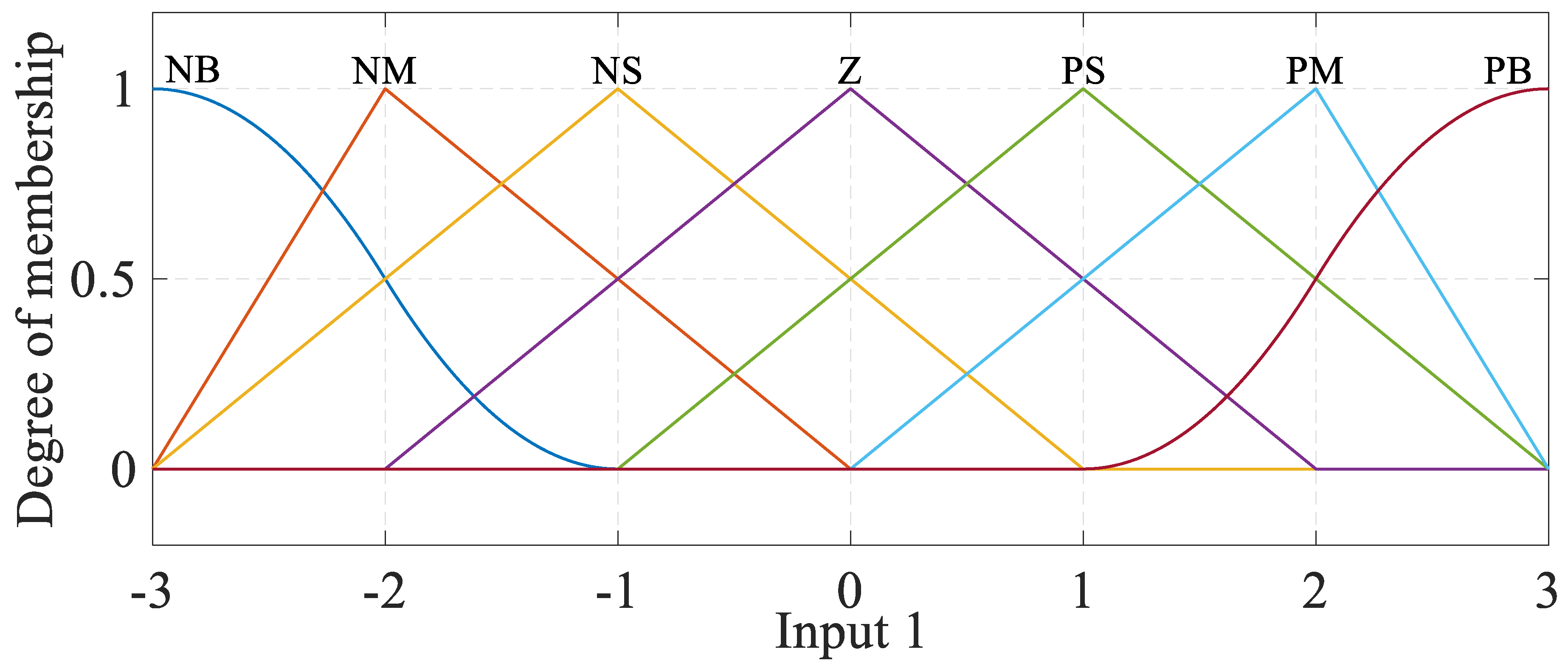
This study proposes a fuzzy controller to track the obtained generator speed. For this purpose, the generator angular speed and wind turbine actuator sensors are considered as the FLC inputs. Each input has a series of membership functions, fuzzy numbers, and linguistic variables.
Figure 5 illustrates the input of the generator speed sensor. Also,
Figure 6 shows the input of the wind turbine actuator sensor in the fuzzy controller. The rule base of the FLC is usually obtained from expert knowledge or heuristics, and it contains a set of 49 fuzzy rules expressed as a set of IF-THEN rules, as follows [
30]:
where
x1,
x2, and
y are input1 variable, input2 variable, and control variable, respectively.
F1 and
F2 illustrate the fuzzy sets of input1 and input2, and
R(
i) shows the fuzzy set of the control variable. The control rules are designed to assign a fuzzy set of the control input y for each combination of fuzzy sets of
x1 and
x2.
Table 1 shows the rules for the FLC.
where
NB,
NM,
NS,
ZR,
PS,
PM,
PB,
B, and
S are fuzzy set labels defined in
Table 2.
Figure 5 shows the input of the generator speed sensor of the wind turbine in the fuzzy controller.
Table 3 illustrates the membership functions, fuzzy set labels, and fuzzy numbers of each variable.
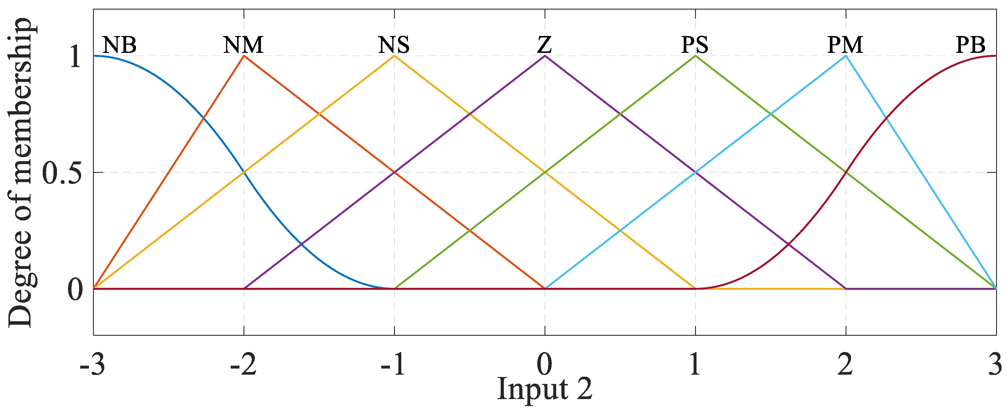
Figure 6 shows the input of the wind turbine actuator sensor in the fuzzy controller, and
Table 4. represents membership functions, fuzzy set labels, and fuzzy numbers of each variable.
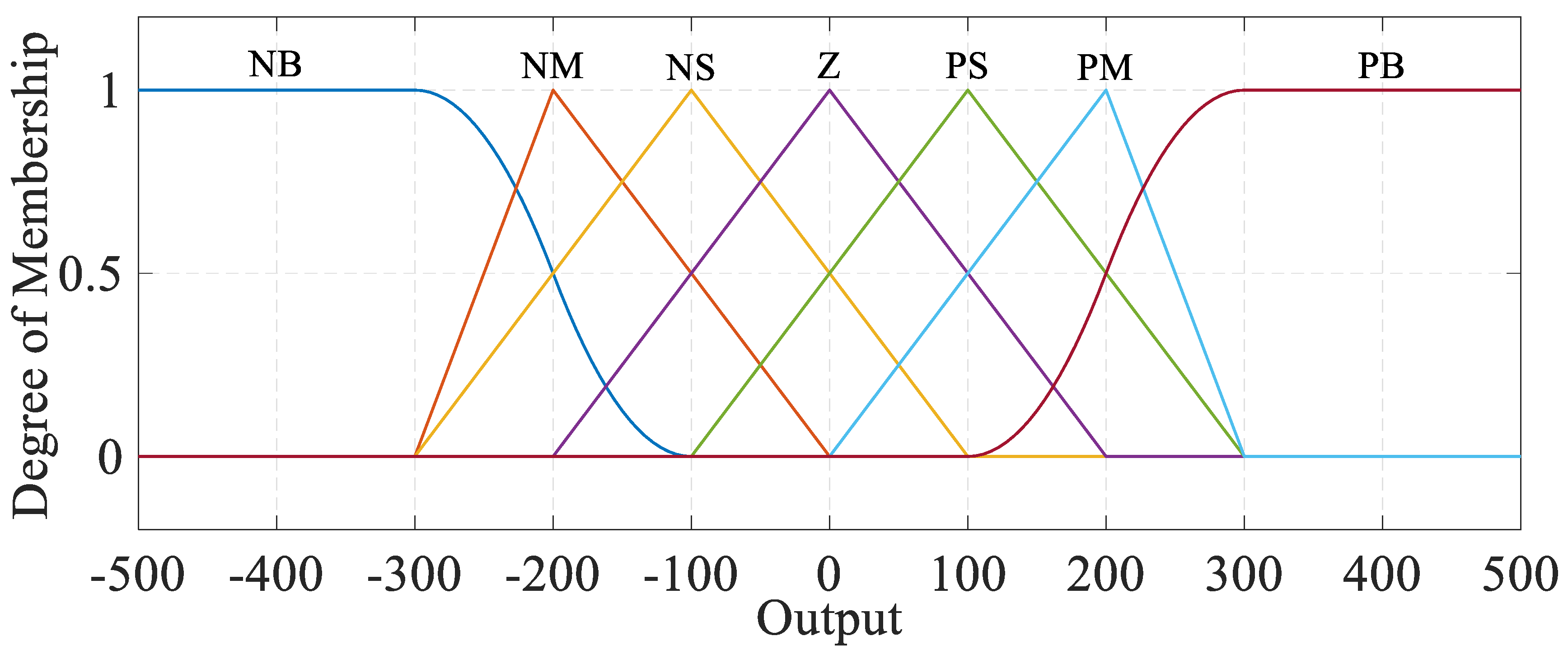
Figure 7 shows the FLC output membership functions, and
Table 5. represents membership functions, fuzzy set labels, and fuzzy numbers for each variable.


 ,
, 


