Article

Simulation-Assisted Determination of the Start-Up Time of a Polymer Electrolyte Fuel Cell

1
Institute of Chemical Engineering and Environmental Technology, Graz University of Technology, Inffeldgasse 25C, 8010 Graz, Austria
2
Faculty of Electrical Engineering, Mechanical Engineering and Naval Architecture, University of Split, R. Boškovića 32, 21000 Split, Croatia
*
Authors to whom correspondence should be addressed.
Energies 2021, 14(23), 7929; https://doi.org/10.3390/en14237929
Submission received: 28 October 2021 / Revised: 17 November 2021 / Accepted: 18 November 2021 / Published: 26 November 2021

Abstract

:
Fuel starvation is a major cause of anode corrosion in low temperature polymer electrolyte fuel cells. The fuel cell start-up is a critical step, as hydrogen may not yet be evenly distributed in the active area, leading to local starvation. The present work investigates the hydrogen distribution and risk for starvation during start-up and after nitrogen purge by extending an existing computational fluid dynamic model to capture transient behavior. The results of the numerical model are compared with detailed experimental analysis on a 25 cm2 triple serpentine flow field with good agreement in all aspects and a required time step size of 1 s. This is two to three orders of magnitude larger than the time steps used by other works, resulting in reasonably quick calculation times (e.g., 3 min calculation time for 1 s of experimental testing time using a 2 million element mesh).

1. Introduction

Through the increased urgency for a transition to a renewable energy supply chain, fuel cells and hydrogen technologies are experiencing unprecedented attention. Facilitated by a vast number of regional and international funding schemes, the respective technologies are in the process of being established on the market. However, to this day, fuel cells in real application often lag behind in durability. Furthermore, in order to increase the reliability of systems, operational strategies are crucial. Whereas a good operating strategy can ensure stable, reliable and long lifetime, a poorly chosen strategy can mean the early and sudden death of critical components. Two critical steps in the operation of a fuel cell are start-up and shut-down. There, the presence of an air-hydrogen front during the start-stop process is a particularly well-known and understood trigger for severe cathode degradation and alternative strategies have been explored [1,2,3]; though not all of these are successful, and harm can even be done. Another critical step in any operation strategy is the application of a load after introduction of the reactant gases. Fuel cell polymer electrolyte membranes are known to suffer from exposure to open circuit voltage (OCV) and the duration of OCV hold times should therefore be limited [4,5,6].
In order to limit the duration of OCV, but also to limit fuel efficiency losses by long reactant purge durations and achieve rapid start-up goals, a general aim is to apply a load fast. However, overall cell or stack voltages give little insight into the gas distribution within the fuel cell. Thus, there is a risk of reactant starvation due to an uneven distribution over the surface area. For the cathode, this is not without impact, though the effect is less immediate [7]. On the anode on the other hand, this can lead to fuel starvation, which is known to be detrimental for fuel cell anodes [8]. In that case, instead of the oxidation of hydrogen according to Equation (1), carbon present in the catalyst support, microporous layer, gas diffusion layer and in some cases bipolar plate, is oxidized according to Equation (2). This leads to the irreversible structural change of the carbon based materials, which impacts mass transport, including water transport, conductivity, and electrochemically active surface area (ECSA) available for the catalytic reaction due to detachment of the catalyst [7,9].
2   H 2   4   H + + 4   e
C + 2   H 2 O   C O 2 + 4   H + + 4   e
Thus, the adequate waiting time before starting operation of a fuel cell is critical to ensure a save and long usable lifetime. In an approach to connect modelling and experiments, the present study investigates the limits of the reliability of the voltage measurement to define the save starting point of operation.
Computational fluid dynamics (CFD) analysis of transient performance in proton exchange membrane (PEM) fuel cells is a relatively scarce topic in the literature. Most of the numerical models are dealing with steady-state analysis where the objective of the research is to mutually compare different flow fields under stationary operating conditions. Since one of the main objectives of research and development of PEM fuel cells is to serve automotive applications, the transient operation needs to be studied in more detail.
In [10,11,12], CFD models are developed to study transient behavior of a PEM fuel cell using 1D and 2D approach, single-phase assumptions, and using a time-step size of 2 × 10⁻⁴ s [11]. The advantage of this approach is quick calculation times, while the disadvantage is that they can only be used for very simplified channel geometries. Shimpalee [13] studies the dynamic performance during a dynamic load cycle of the Federal Urban Drive Cycle of a large scale PEM fuel cell model using CFD and STAR-CCM+ software by Siemens Digital Industries Software. Two different flow fields of 200 cm2 active area are studied and mutually compared. They showed different transient behavior, although under steady-state operation, they were observed as quite similar. Shimpalee [13] developed a dynamic CFD model of a 200 cm2 single-cell that showed quite similar behavior for steady-state and dynamic models. Nevertheless, the model lacks detailed experimental validation. Tolj et al. [14] developed a simplified 3D CFD model of 1 kW stack and studied the dynamic process of heating up from room temperature, comparing the numerical vs. lumped model approach and experimental data. The model used simplified channel geometry, a continuum layer approach and symmetry boundary conditions but resulted in good agreement vs. other data. Nevertheless, detailed comparisons with experimental data was lacking in all of the previous works [10,11,12,13,14]. Detailed numerical model validation can be seen in Penga et al. [15] where a steady-state 3D CFD model of a 100 cm2 single cell with complex flow field geometry is developed and the numerical results are compared with neutron imaging results. Experimental investigation was semi-steady-state, conducted using current ramp up and ramp down with 10 min hold times. The conducted CFD analysis has shown that the steady-state approach using humidified and dry reactants shows quite similar results when compared to neutron radiography but also concludes that 10 min hold times are not sufficiently long for reaching steady-state operation during experimental analysis and suggests using longer hold times. The numerical model consisted of 20+ million elements, therefore any type of transient analysis would take a very long time to be conducted.
The model developed by Penga et al. [15] is also used in this work, but for transient analysis and with deactivated multi-phase modelling because it requires very small time-steps and immense computational resources and calculation times. As it can be seen from the mentioned references [10,11,12,13,14], the numerical modelling is generally based on significantly simplified geometry when compared to the experimental setup and most of the works lack experimental validation. The geometry and process simplifications are rationalized by very high calculation time requirements for such modelling approaches to give accurate predictions. For example, as can be seen in [11,13], the time step sizes were 0.2 and 1 ms, respectively.
The objective of this work was to develop a full-scale 3D CFD model with capability of using higher time-scales to compare the results with experimentally obtained data for different quantities and see if the numerical model can give a good prediction of gas transport and cell behavior during a current-ramp up after a dry nitrogen purge. This is done in a combined experimental and modelling approach for a 25 cm2 single cell with a triple serpentine flow field on anode and cathode. Currently, the limitations of the developed model are outlined in the inability to accurately model two-phase flow, due to an immense increase in the calculation requirements; therefore, this issue will be tackled in a future study. Since there are only a few other transient CFD models of a full-scale single cell, with only minor or mostly without any form of experimental validation, this is to date the most thoroughly validated transient CFD model of PEM fuel cells.

2. Experimental

2.1. Materials and Equipment

All experiments were carried out in a 25 cm2 single cell hardware with a pneumatic cell compression unit both manufactured by balticFuelCells, Germany, shown in the right image in Figure 1. The catalyst coated membrane (CCM) features a 15 µm thick perfluoro sulfonic acid (PFSA) based membrane with a carbon supported Pt catalyst (loading: 0.05 mg Pt cm−2 and 0.25 mg Pt cm−2 on anode and cathode, respectively). Polytetrafluoroethylene (PTFE)-treated carbon paper with a micro-porous layer (MPL) is used as the gas diffusion layer (GDL). CCM and GDLs are sandwiched between triple serpentine flow field plates made of graphite composite (Figure 2, bottom images).
The cell tests are performed on a G60 fuel cell test station manufactured by Greenlight Innovation. The G60 is used to control gas inlet line temperatures, anode and cathode pressure, gas flow rates and humidity. The cell is heated via an external thermostat. The setup is shown in the left image of Figure 1.
If not stated differently in the following experimental descriptions, pure hydrogen and synthetic air with an O2 content of 20.5% v/v are used as reactants, and pure N2 serves as inert gas to purge the cell.

2.2. Gas Analysis

For the exhaust gas measurements, the test station’s exhaust lines are connected to an ABB Advance Optima AO2020 continuous gas analyzer, capable of measuring the concentration of CO, CO2, O2 and H2 in a known gas flow.
To determine the dead time of the experimental setup consisting of the G60 test station, the test cell and the gas analyzer, gas measurements were carried out while alternating reactant gases and N2. Those were done without cell, where the G60’s inlet and outlet lines were directly connected. Regarding temperature (T), pressure (p) and flow rates, the same settings as shown in Table 1 were used.
First, the anode line was flushed with dry N2 until there was a stable signal at the gas analyzer. The gas recipe is then changed to H2 while maintaining a constant flow rate. After the gas analyzer signal stabilized at almost 100% H2, the system was again flushed with dry N2 as done before. The experiment was repeated in a similar way at the cathode line, alternating synthetic air and dry N2.
Due to the dead volume in the test station lines, as well as response times for valves, the gas analysis time scale was corrected to the measured voltage so that the onset of the increase of voltage matches the increase of concentration.

2.3. Fuel Cell Conditioning

Fresh CCMs are conditioned for 8 h by potential cycling similar to the method described by Bezmalinović et al. [16]. The cell potential is varied between 0.4 V, 0.5 V and 0.6 V. During conditioning, the cell is operated at 80 °C and 100 kPa(g) inlet pressure. Gas flow rates are 0.4 normal liters per minute (NLPM) and 1.2 NLPM for H2 and air, respectively, and both reactant gases are humidified to 80% relative humidity (RH).

2.4. Fuel Cell Start-Up and Shut-Down Procedure

This start-up and shut-down strategy is a modified version of the O2 consumption strategy A described by Kocher et al. [17]. The operating parameters are shown in Table 1. The cell is left at OCV until a potential of 0.8 V is exceeded for 20 s. Then a galvanostatic load at 12.5 A with a 12.5 s ramp is applied for 10 min, after which the current is ramped down to 0 A over 12.5 s. This ramp rate is chosen as it reliably leads to a save start-up in the G60 test station. Too high ramp rates may lead to emergency shut-down if the cell voltage drops suddenly. After a 10 s pause, the dry bypass is opened and the cell is purged with N2 until the cell potential stays below 0.1 V for 60 s, after which the cycle is repeated.

3. Modelling Approach

3.1. Numerical Domains

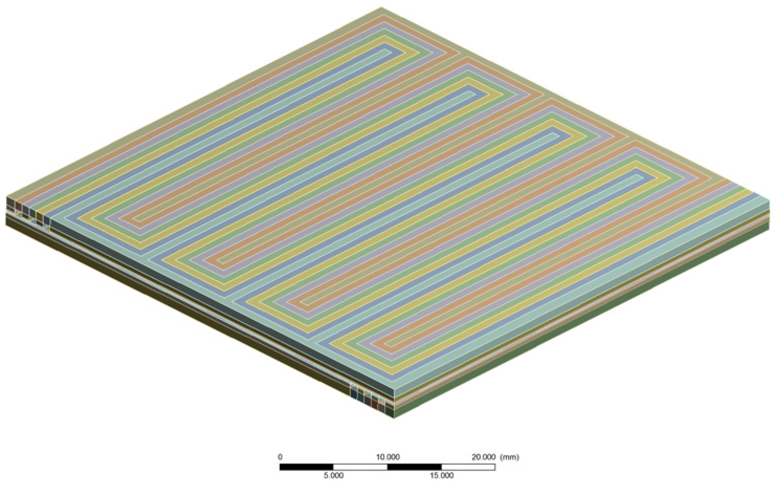
The geometry is based on the experimental setup shown in Figure 1. The anode and cathode flow fields consist of triple serpentines with channel width of 0.9 mm and channel depth of 0.45 mm, while the land/channel ratio is equal to 1. The active area of the cell is 25 cm2. The flow direction is “counter-flow”.
The geometry is decomposed into high number of smaller blocks to enable genesis of fully structured mesh, which will give accurate results and minimize the calculation time. The decomposed geometry is shown in Figure 3.
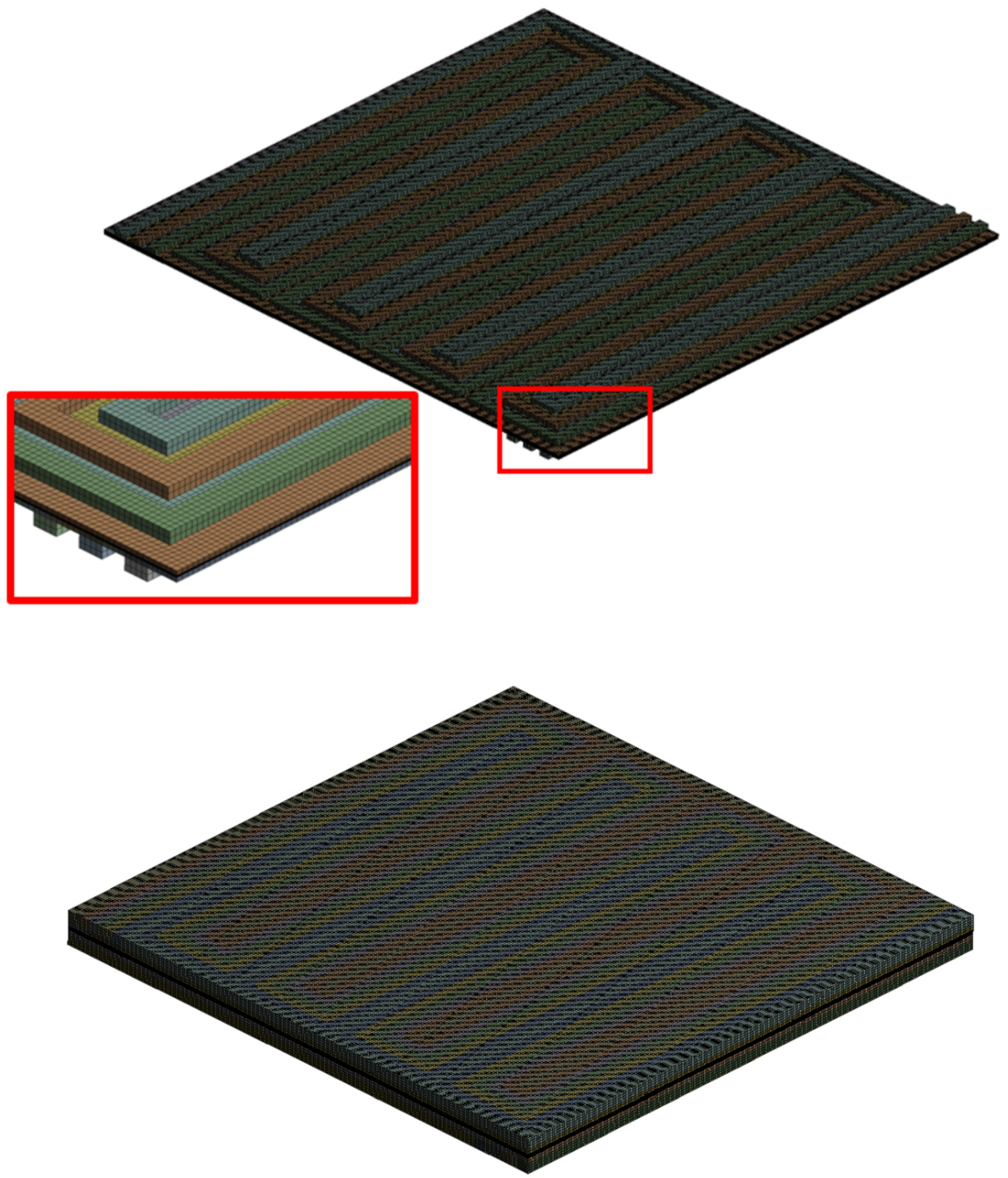
A fully structured mesh is generated using a uniform element sizing of 0.225 mm. The channels and lands are further subdivided along the height and width into 4 subdivisions. Each layer of the MEA (gas diffusion substrates, MPLs, catalyst layers, membrane) are subdivided using 4 elements across the height, as shown in Figure 4. Minimal orthogonal quality of the generated mesh is very high with value of 0.976. Total number of elements is 1.998 M.
The thickness of layers is shown below in Table 2.

3.2. Model Calibration and Execution

An experimental polarization curve using 1 h hold times and relatively dry operating conditions was used as a reference for calibration of the cathode reference exchange current density and concentration exponent in the numerical model. Such prolonged hold times and operating conditions were necessary to avoid regions of unstable behavior due to high accumulation of liquid water at increased current densities—as explained in a previous study [15]. The governing equations of the numerical model are shown in the following chapter.

3.3. Governing Equations

The governing equations are resolved using the ANSYS Fluent®® v 17.2 software (ANSYS, Canonsburg, PA, USA) including PEMFC add-on. The equations are listed below. The equations are adopted from references [18,19,20,21,22,23,24,25]. Detailed explanation of the equations and parameters is given in [15].
  • Electrochemistry
( σ s o l ϕ s o l ) + R s o l = 0
( σ m e m ϕ m e m ) + R m e m = 0
R s o l = R a n ( < 0 )
R s o l = + R c a t ( > 0 )
R m e m = + R a n ( > 0 )
R m e m = R c a t ( < 0 )
R a n = ( ζ a n j a n ( T ) ) ( [ A ] [ A ] r e f ) γ a n ( e α a n a n F η a n R T + e α c a t a n F η a n R T )
R c a t = ( ζ c a t j c a t ( T ) ) ( [ C ] [ C ] r e f ) γ c a t ( e α a n c a t F η c a t R T + e α c a t c a t F η c a t R T )
R a n = ζ a n j a n ( T ) ( [ A ] [ A ] r e f ) γ a n ( e α a n F η a n R T )
R c a t = ζ c a t j c a t ( T ) ( [ C ] [ C ] r e f ) γ c a t ( e α c a t F η c a t R T )
j a n ( T ) = j a n r e f e E a n R T ( 1 T T a n r e f )
j c a t ( T ) = j c a t r e f e E c a t R T ( 1 T T c a t r e f )
η a n = ϕ s o l ϕ m e m U a n 0
η c a t = ϕ s o l ϕ m e m U c a t 0
U a n 0 = E a n 0 Δ S a n 2 F ( T T 0 ) R T 2 F l n ( p H 2 p 0 )
U c a t 0 = E c a t 0 + Δ S c a t 2 F ( T T 0 ) R T 2 F l n ( p H 2 O p s a t p O 2 p 0 )
  • Cathode Particle Model
R c a t = 4 F c O 2 c O 2 j O 2 i d e a l + i o n + l i q
l i q = ζ c a t r p 2 K w D w 1 + S ε 1 ε 3 3 ( 1 ε )
j O 2 i d e a l = R c a t 0 4 F
  • Conservation of Current and Mass
S H 2 = M w , H 2 2 F R a n < 0
S O 2 = M w , O 2 4 F R c a t < 0
S λ = M w , H 2 O 2 F R c a t > 0
a n R a n d V = c a t R c a t d V
  • Water Transport and Mass Transfer
t ( ε i M w , H 2 O ρ i λ E W ) + ( i m n d M w , H 2 O F ) = ( M w , H 2 O D w i λ ) + S λ + S g d + S l d
S g d = ( 1 s θ ) γ g d M w , H 2 O ρ i E W ( λ e q λ )
S l d = s θ γ l d M w , H 2 O ρ i E W ( λ e q λ )
λ e q = 0.36 + 6 a ( 1 t a n h ( a 0.5 ) ) + 0.69 ( λ a = 1 3.52 ) a 0.5 ( 1 + t a n h ( a 0.89 0.23 ) ) + s ( λ s = 1 λ a = 1 )
a = p w v p s a t
t ( ε i ρ l s ) = ( ρ l K K r μ l p l ) + S g l S l d
K r = s b
K r = ( M w , H 2 O ρ l λ S = 1 + E W ρ i M w , H 2 O ρ l λ + E W ρ i λ λ s = 1 ) 2
t ( ε i ρ l s ) = ( ρ l K K r μ l ( p c + p ) ) + S g l S l d
S g l = γ e ε s D g l   M w , H 2 O R T p l n ( p p s a t p p w v )  
S g l = γ c ε ( 1 s ) D g l   M w , H 2 O R T p l n ( p p s a t p p w v )  
D g l = 0.365 10 4 ( T 343 ) 2.334 ( 10 5 p )
D g l = 1.79 10 4 ( T 343 ) 2.334 ( 10 5 p )
f l i q = Θ ε   s m a x [ ( p c + 1 2 ρ v 2 ) , 0 ]
p c = σ c o s θ c ε K J ( 1 s )
p c = σ c o s θ c ε K J ( s )
J ( x ) = a x b x 2 + c x 3
R j = ( 1 s ) γ j R j
t ( ρ l s ) + ( ρ l v l s ) = ( D l i q s )
v l = χ v g
  • Heat Sources
S G D L + M P L = i s 2 σ s o l S g l * L
S A C L = R a n ( η a n T Δ S a n 2 F ) + i s 2 σ s o l + i m 2 σ m e m ( S d l + S g l ) L
S C C L = R c a t ( η c a t T Δ S c a t 2 F ) + i s 2 σ s o l + i m 2 σ m e m ( S d l + S g l ) L
S M E M = i m 2 σ m e m
S C C = i s 2 σ s o l
  • Properties
D i = ε 1.5 ( 1 s ) r s D i 0 ( p 0 p ) γ p ( T T 0 ) γ t
D e f f i j = ( 1 s ) r s ε 1.5 D i j
σ m e m = Γ i ( 0.514 λ 0.326 ) ω i e E i ( 1 303 + 1 T )
Γ i = β m e m
Γ i = β a n ς a τ a
Γ i = β c a t ς c τ c
D w i = η λ ρ i E W f ( λ )
f ( λ ) = 4.1 10 10 ( λ 25 ) 0.15 [ 1 + t a n h ( λ 2.5 1.4 ) ]
f ( λ ) = 3.1 10 7 λ ( e 0.28 λ 1 ) ( e 2346   [ K ] T )
f ( λ ) = 4.17 10 4 λ ( 1 + 161 e λ ) ( e 2346   [ K ] T )
n d = n o s m g ( λ )
g ( λ ) = 2.5 λ 22
l o g 10 p s a t = a + b t + c t 2 + d t 3
  • Cross-Over Current
S H 2 = M w , H 2 2 F I l V o l a n
S O 2 = M w , O 2 4 F I l V o l c a t
S λ = M w , H 2 O 2 F I l V o l c a t

4. Results and Discussion

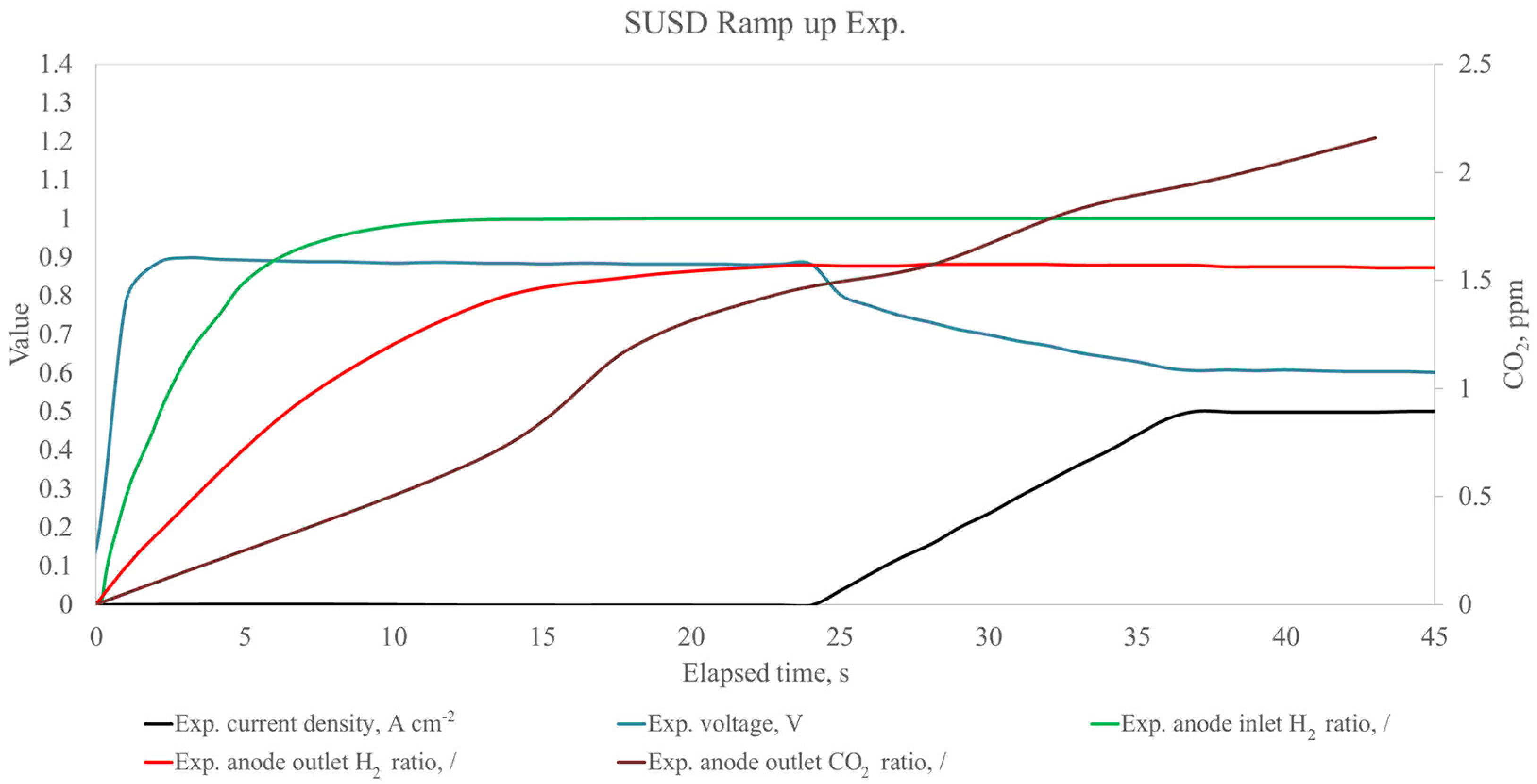
During start-up of the fuel cell and with the introduction of hydrogen, the voltage rapidly increases and reaches a maximum before the gas measurement shows a hydrogen ratio of 1 (Figure 5) for the respective measurement with the cell bypassed. During the experiment in the course of the start-up and shut-down cycling, the outlet gas compositions remains below 1 even longer. At the point at which the current ramp-up is initiated by the procedure, the hydrogen ratio is at 0.880 with the consumption outweighing the replacement of remaining nitrogen, so that a marginal decrease to 0.878 is noted before the ratio again increases, but not reaching a value above 0.882.
Interestingly, the observed amount of CO2 does not appear to be directly related to the ramp up of the current, as it is already observed before its onset. However, there is a correlation—though with delay—with the hydrogen front moving through the fuel cell.
The initial state of the cell in the numerical model is set up by conducting a steady-state analysis using dry nitrogen with 0.4 NLPM on anode and cathode side. The time-step dependency analysis has been carried out and outlined that it is possible to use greater time steps compared to those found in other references when the water phase change model is turned off. For this reason, the mist flow assumption, i.e., single-phase, is used. Using the phase change model resulted in solution divergence even when time steps of several ms were used. Since the duration of the entire cycle is 30 s with dry nitrogen plus 45 s after the reactants are introduced, it is easy to see that using greater time step results in orders of magnitude reduction in calculation times because the number of required time steps for conducting the simulations for the total elapsed time are reduced. Using the mist flow assumption is also convenient because the start-up of the dynamic load profile is from dry reactants and the reactants have a relative humidity of 80% and 60% for anode and cathode side, respectively. Therefore, liquid water only occurs after the current ramp-up to 0.5 A cm−2 and the quantity of liquid water is minor. The time step dependency study was carried out for different time steps and it was noted that time step size of 1 s gives satisfactory level of agreement with experimental data in all aspects, while larger time step sizes gave poor results. After the steady state solution has converged (dry nitrogen both sides, current density of 0 A cm−2), the solution type is changed to transient and time step of 1 s is applied. The liquid phase equations are turned off due to reasons specified previously and the transient solver is running for total time of 30 s, which was enough to show that all of the monitored variables remain at a fixed value. This includes the mass fractions of different gas species, relative humidity and temperature at the anode and cathode outlets and inlets, as well as current density and electric potential at the cathode terminal. Galvanostatic approach was used. After 30 s total time has elapsed, the solution is stopped and the gas compositions and mass flow rates are changed to be in agreement with experimentally obtained data. After the 30 s have elapsed, the new start is considered as zero flow time. This represents the introduction of the reactants into the cell. It was noted that the abrupt change in gas composition from the initial dry nitrogen to humidified reactants with stable mass flow rates equal to 0.4 NLPM and specified relative humidity gives very different results at the outlet when compared to experimental data. It was assumed that this behavior is present due to long pipes before and after the cell, which affect the replacement of nitrogen once the valves are operated. The experiments were carried out once again and it was noted that the change in anode inlet is actually quite inert and it takes about 16 s to reach hydrogen ratio of 1 at the anode inlet, while at the anode outlet, the hydrogen ratio was equal to ca. 0.9. It was concluded that this is a result of nitrogen cross-over. The water vapor was taken out of the account by condensing the water before the gas analyzer at temperature of +3 °C. It was noted that the anode inlet composition gradually changed from initial value of 0 to the value specified experimentally. This gradual change could not be implemented in the CFD model for every 1 s because the solution would diverge; thus, it was changed manually every 4 s in a step like manner (green triangles in Figure 6). Once this procedure was carried out, the results of the simulations and experimental data have shown good agreement in the initial part of the ramp-up profile, as seen in Figure 6. After 16 s have elapsed, the gas composition is kept at a constant value and the simulation is carried out until a flow time of 24 s and stopped. The current density is then ramped up throughout a total time of 12.5 s from an initial value of 0 A cm−2 to final value of 0.5 A cm−2. After each 1 s time step has elapsed, the value of current density at the cathode terminal was altered to agree with experimentally obtained data by gradually increasing the value at each time step.
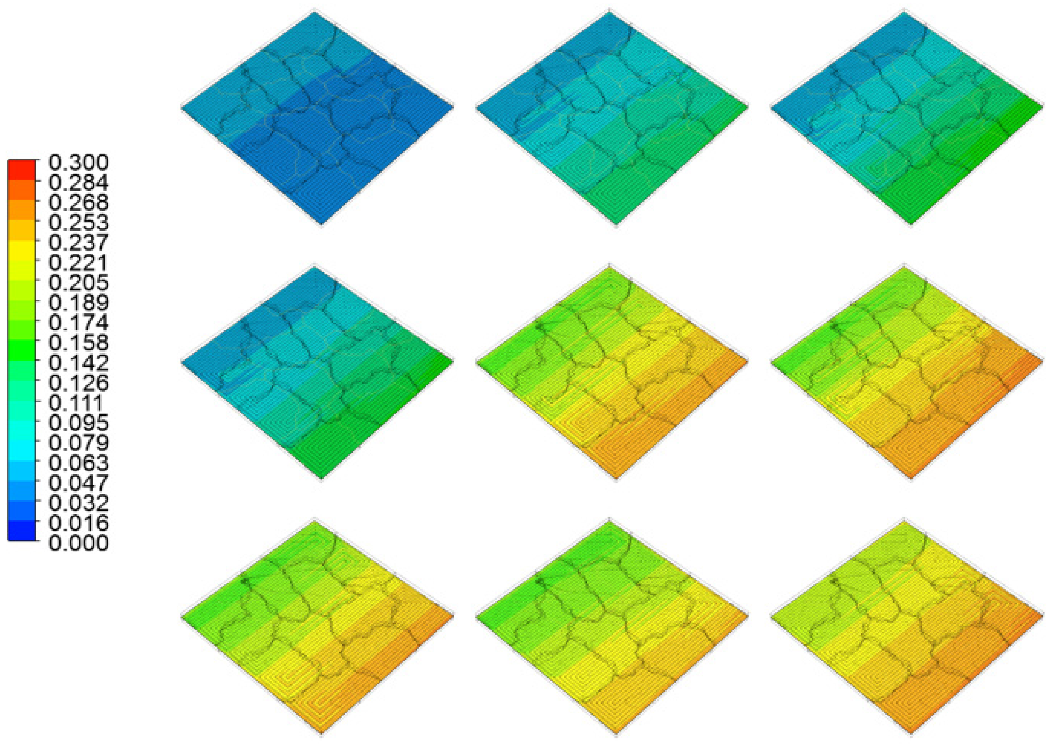
Since the hydrogen ratio has increased from 0 to 1 at the inlet during the total time of 16 s, the hydrogen mass fraction contours have been extracted for each 1 s time step during total time of 18 s, as shown in Figure 7, to elucidate regions where the hydrogen is in lowest concentration. It can be seen that in the beginning, the hydrogen mass fraction is at its highest value at the inlet, but after a couple of seconds, it can be observed that the hydrogen mass fraction is at its highest value at the outlet, which seems counter-intuitive at first.
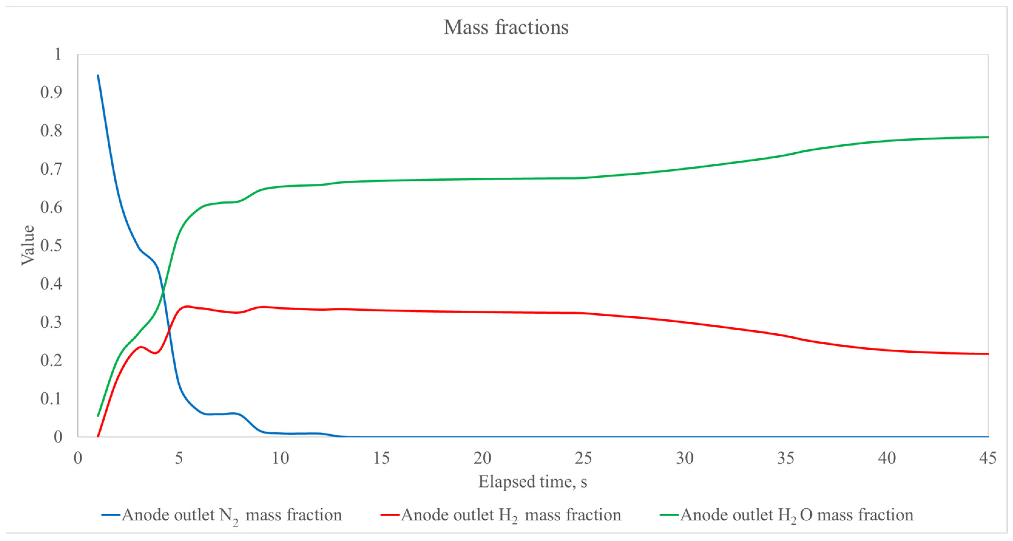
To explain this behavior, the mass fraction of each species is plotted in Figure 8. The total sum of mass fractions of each species must be equal to one at all times. It can be seen in Figure 8 that the anode nitrogen mass fraction abruptly decreases in value during the first couple of seconds. Since the nitrogen is expelled from the cell, the total of mass fractions must remain 1, meaning that the mass fractions of the other two species, hydrogen and water vapor, will consequently increase. It can also be observed that once the nitrogen mass fraction drops to zero, at time 16 s in the chart, the hydrogen and water vapor mass fractions remain at their constant values until the time of 24 s. From that moment onwards, the hydrogen mass fraction is gradually decreased while the water vapor mass fraction is increased, during the current ramp up, because the cell starts producing water while hydrogen is being consumed. After the final current density of 0.5 A cm−2 is reached, the hydrogen and water vapor mass fractions reach a constant value which remains until the end of the cycle.
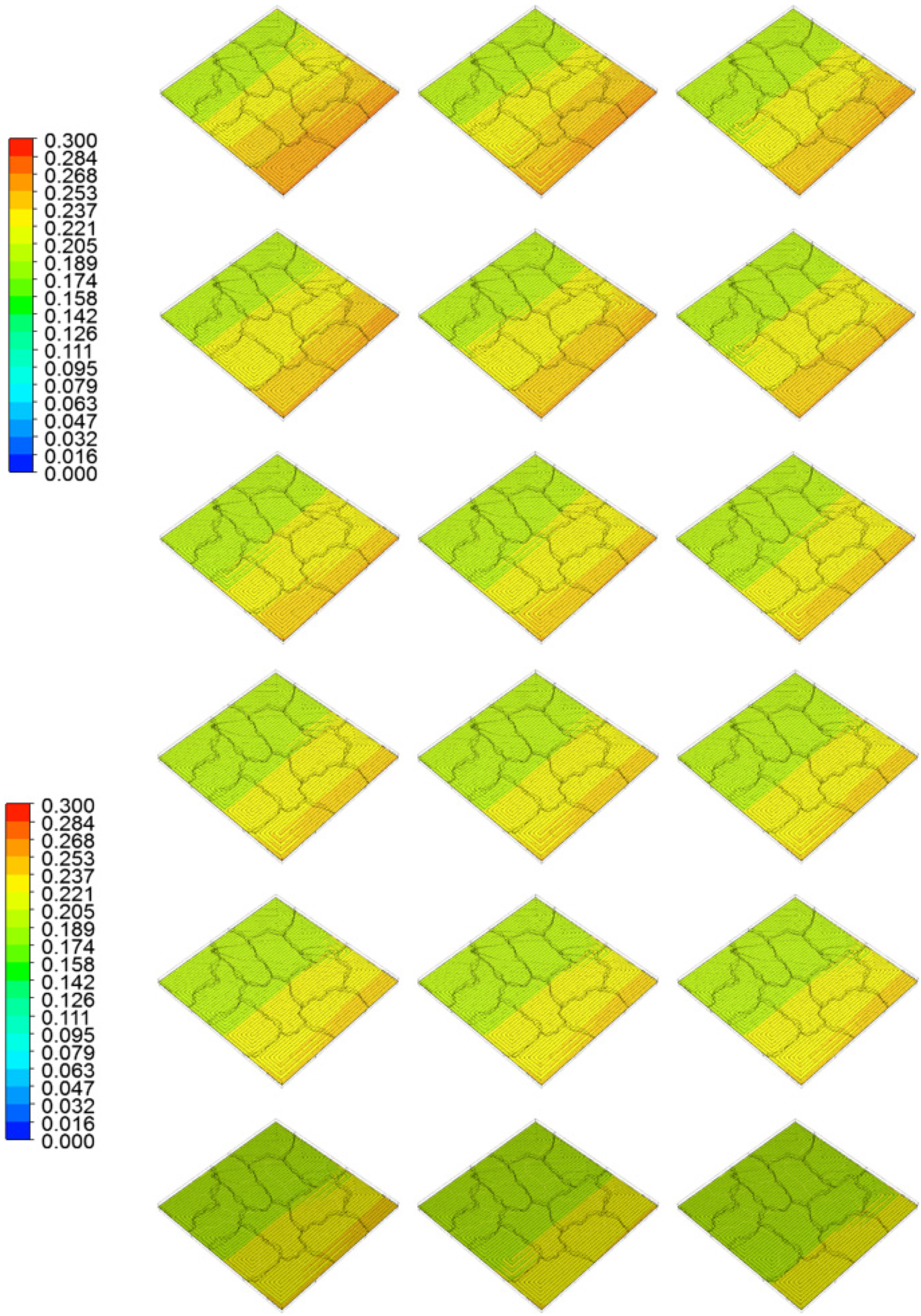
Figure 9 shows hydrogen mass fraction contours inside the anode catalyst layer for time 10 s to 27 s. It can be observed that spatial distribution of the hydrogen mass fraction evens out from time 16 s to 24 s and then it can be observed that the mass fraction values become quite uniform, during the current ramp up process. The current ramp up lasts 12.5 s and the current density is linearly increased from 0 to 0.5 A cm−2 at the end.
During the ramp up, it can be seen that the hydrogen mass fraction gets evened out due to reactant depletion and we can observe for time 30 s in Figure 10 that the lowest hydrogen mass fraction appears in the middle of the active area, and then gradually shifts in the direction of the anode outlet, while the hydrogen mass fraction is the highest at the inlet. This is expected since the reactant gas is consumed in the downstream direction. After time 36 s, the hydrogen mass fractions remain almost identically distributed, since the final current density of 0.5 A cm−2 is reached. It can be seen that during this process, there are no regions in which starvation occurs. Therefore, it can be concluded that the hydrogen purging duration and ramp-up speed is sufficient to prevent degradation of the cell.
If we observe the current ramp up, it seems to have very little effect on the hydrogen mass fraction distribution along the entire flow field, meaning that starvation is not likely to occur. The ramp up of the current exhibits only a marginal impact on the gas distribution and does not show a clear connection to the observed emission of CO2. This allows the conclusion that a small degree of carbon corrosion is most likely linked to a combination of mechanisms. Traces of oxygen in test station anode piping, and most importantly from cross over of oxygen from the cathode towards the anode, can recombine with hydrogen as it is introduced, and lead to localized heat up at the active catalyst sites. Increased temperatures and the presence of catalyst and water favor the oxidation of carbon, which is evident from the emission of CO2. This conclusion is supported by the consistently lower hydrogen concentration at the outlet of the cell compared to when the cell is bypassed as well as when simulated.

5. Conclusions

The present study links the observed carbon dioxide emissions to damage occurring during fuel cell start-up by time-resolved CFD modelling. The novel aspects of this paper are in the transient modelling of a full-scale single cell with relatively high time step size of 1 s for the first time. Other authors have done so using time steps of several ms or lower, resulting in a limited applicability of the method due to excessive calculation times. Our approach has led to a reduced time requirement for conducting such calculations by several orders of magnitude (e.g., the total simulation time of 75 s lasts 3 h and 15 min using time step of 1 s, while it would take ca. 156.25 days if time step of 1 ms would be used, if done on the same computer). This was accomplished by using a very high mesh quality, mist flow assumption and operating conditions in which such an approach is feasible; meaning moderately humidified reactants and current density. The measured voltage values correlate with the results of the simulation by approximately ±10% with—as is to be expected—the biggest error shortly before and during ramp-up of the current. This is due to the fact that the simulation has limited capabilities to include gas crossover, which leads to an overestimation of the voltage during an extended time at open circuit voltage. With increasing current, the simulation tends to underestimate the fuel cell voltage. This is less pronounced during stable operation. The model relies on one value at 0.5 A cm−2 for the membrane resistance. In reality, this will not be stable over a whole range of current setpoints and thus, the error most likely stems from the input parameter of the membrane resistance. The hydrogen concentrations at inlet and outlet exhibit rather large errors in the beginning of the experiment, when the model tends to overestimate the hydrogen concentration. This, however, equilibrates within the first 10–15 s and stabilizes in the range of 0–1% for the inlet and −4–0% (and thus, overestimating the concentration) for the outlet.
Despite this initial sensitivity, it is shown that the sharp rise of cell voltage once reactant gases are introduced, is unrelated to the local hydrogen concentration in the anode and there is a risk of initiating operation too early. With the used adequate absolute flow, there is sufficient reactant present to safely operate the cell and no direct link between current and CO2 emission was observed despite a hydrogen ratio below 0.9 in the anode exhaust. The hydrogen ratio mapping showed an even distribution early on with no potential areas exhibiting a high risk of degradation and no link between the onset of the load ramp and the carbon dioxide emissions were observed. This leads to the conclusion that no fuel starvation has occurred. The observed CO2 emissions—though low—appeared to rather be linked to the introduction of the reactant gases than to a local undersupply of hydrogen. This is more likely connected to a direct combination of hydrogen and oxygen due to crossover of gases, which leads to a localized heat up at the catalyst interface, which in turn accelerated carbon corrosion in the presence of water. This hypothesis is supported by the overestimation of the voltage in the latter stages of OCV as well as the overestimation of the hydrogen content in the fuel cell anode outlet, as both these values are affected by gas crossover through the membrane.
The model has also shown that during the experiments, it is very important to measure the inlet and outlet chemical composition of gases, because for this particular case, the valves, tubes and membrane integrity had more severe influence on the behavior—and in particular, the degradation of the cell—than actual reactant starvation during the current ramp-up.
The developed numerical model will be used in future studies to study the performance of PEM fuel cell operated using standard drive cycles and the results will be compared with locally measured current density distribution.

Author Contributions

Conceptualization, M.B. and Ž.P.; methodology, M.B. and Ž.P.; software, Ž.P.; validation, M.B. and W.L.; formal analysis, M.B., Ž.P. and W.L.; investigation, W.L.; resources, M.B.; data curation, Ž.P.; writing—original draft preparation, M.B.; writing—review and editing, Ž.P., M.H. and V.H.; visualization, Ž.P.; supervision, V.H.; project administration, M.B. and Ž.P.; funding acquisition, M.B., V.H. and Ž.P. All authors have read and agreed to the published version of the manuscript.

Funding

Open Access Funding by the Graz University of Technology. Experimental work done by the team at TU Graz was supported by the Austrian Research Promotion Agency (FFG) through the PROTECT project under the 9th call of the program Mobilität der Zukunft as well as the HyTechonomy project, which received financial support by Österreichische Forschungsförderungsgesellschaft mbH (FFG) FFG-COMET-Projekt and the Steirische Wirtschaftsförderungsgesellschaft mbH (SFG). Research conducted by Dr. Željko Penga was supported under the project STIM–REI (contract number: KK.01.1.1.01.0003), funded by the European Union through the European Regional Development Fund—the Operational Programme Competitiveness and Cohesion 2014–2020 (KK.01.1.1.01.).

Conflicts of Interest

The authors declare no conflict of interest.

Nomenclature

A anode
a water activity,/
C cathode
CCMcatalyst coated membrane
CFDcomputational fluid dynamics
c w specific heat of water, J (kg K)−1
D g l diffusion coefficient between gas and liquid phase,/
D l i q liquid water diffusion coefficient, kg m−2 s−1
D i j gas species mass diffusivity, m2 s−1
D e f f i j effective gas species mass diffusivity, m2 s−1
D i 0 mass diffusivity of species i and reference pressure p 0 and temperature T 0 , m2 s−1
D w i diffusion coefficient of water content, kmol m−3
e Euler’s number/constant
E a n / E c a t user-specified activation energy anode/cathode, respectively, J mol−1
E i activation energy for the temperature correction term,/
E a n 0 / E c a t 0 reversible potentials anode/cathode, respectively, V
ECSAelectrochemically active surface area, m2/g
E W equivalent weight, kg kmol−1
F Faraday constant, (9.6485 × 10⁷) C kmol−1
g ( λ ) function for correlation of electro osmotic drag to membrane water content,/
GDLgas diffusion layer
I l leakage current, A m−2
i m the ionic current density, A m−1
i s ,   i m magnitude of solid/membrane phase current density, respectively, A m−1
j a n / j c a t reference exchange current density, respectively, A m−2
j a n r e f / j c a t r e f reference exchange current density at specified reference temperature anode/cathode, respectively, A m−2
j O 2 i d e a l ideal oxygen molar flux, mol m−2 s−1
K absolute permeability,/
K r relative permeability,/
K w D w product of oxygen solubility and diffusivity in liquid water, respectively, m2 s−1
L latent heat of evaporation, J kg−1
MPLmicro porous layer
M w , H 2 ,   M w , O 2 ,   M w , H 2 O ,   M w molecular mass of hydrogen, oxygen, water vapor, ionomer, respectively, kg kmol−1
n d osmotic drag coefficient,/
n o s m user-specified generality coefficient for electro osmotic drag coefficient,/
NLPMnormal liters per minute
OCVopen circuit voltage
p pressure, Pa
p c capillary pressure, Pa
p l liquid pressure gradient, kg m2 s−2
p w v partial pressure of water vapor, Pa
p H 2 , p O 2 , p H 2 O partial pressures of hydrogen, oxygen and water vapor, respectively, Pa
p s a t water vapor saturation pressure, Pa
p 0 user-specified standard state absolute pressure, Pa
p 0 reference pressure, Pa
PEMproton exchange membrane
PEMFCproton exchange membrane fuel cell
PFSAperfluoro sulfonic acid
PTFEpolytetrafluoroethylene
R universal gas constant, (8.3144) J (mol K)−1
R a n / R c a t exchange current density anode/cathode, respectively, A m−3
R j transfer current modification due to occurrence of liquid water, A m−3
r p particle diameter, m
r s exponent of pore blockage,/
R c a t 0 ideal transfer current, A m−2 s−1
R s o l / R m e m volumetric transfer current, respectively, A m−3
i o n / l i q resistance due to ionomer film/liquid water film surrounding particles, respectively, s m−1
RHrelative humidity, %
s liquid saturation,/
S G D L + M P L ,   S A C L ,   S S C C L ,   S M E M ,   S C C volumetric heat source for the gas diffusion layer and micro porous layer, anode catalyst layer, membrane and current collector, respectively, J m−3 s−1
S H 2 ,   S O 2 , S λ , S g d , S l d ,   S g l sink/source terms for hydrogen, oxygen, membrane water content, between gas and dissolved phases, liquid and dissolved phases and gas and liquid phases, respectively, kg m−3 s−1
Δ S a n / Δ S c a t reaction entropies anode/cathode, respectively, J K−1
T temperature, K
T a n r e f / T c a t r e f user-specified reference temperature anode/cathode, respectively,/
T 0 user-specified standard state temperature, K
T 0 reference temperature, K
U a n 0 / U c a t 0 half cell potential anode/cathode, respectively, V
V volume, m3
v g gas velocity vector, m s−1
v l liquid water velocity vector, m s−1
V o l a n / V o l c a t volume of the anode/cathode catalyst layer, m3
[   ] ,   [   ] r e f local species concentration, kmol m−3
Greek alphabet
α a n a n / α c a t a n anode and cathode transfer coefficients of the anode electrode, respectively,/
α a n c a t / α c a t c a t anode and cathode transfer coefficients of the cathode electrode, respectively,/
β m e m , β a n ,   β c a t electrolyte phase conductivity model generality constant in membrane, anode catalyst and cathode catalyst, respectively,/
Γ i electrolyte phase conductivity term,/
γ a n / γ c a t concentration dependence coefficient anode/cathode, respectively,/
γ e / γ c evaporation/condensation coefficient, respectively,/
γ j user-specified constant for modification of transfer current due to occurrence of liquid water,/
γ g d , γ l d user-specified parameters for mass exchange rate between gas and dissolved/liquid and dissolved phases,/
γ t / γ p user-defined exponents in gas species diffusivity equation for temperature/pressure, respectively,/
ε porosity,/
ε i porosity of porous media,/
ζ a n / ζ c a t specific active area anode/cathode (cathode catalyst), respectively, m−1
η a n / η c a t surface over potential anode/cathode, V
Θ coefficient of liquid water removal,/
θ user-specified parameter,/
θ c contact angle, °
λ membrane water content, dissolved water content,/
λ e q equilibrium water content,/
λ a = 1 , λ s = 1 water activity at water activity equal to 1, saturation equal to 1, i.e., user-specified parameters,/
μ l liquid dynamic (absolute) viscosity, kg (ms)−1
ρ i dry ionomer, i.e., membrane, density, kg m−3
ρ l liquid water density, kg m−3
σ surface tension coefficient, N m−1
σ s o l / σ m e m electrical conductivity of the solid/membrane phase, respectively, (Ωm)−1
ς a / ς c ionomer volume fraction anode/cathode, respectively,/
τ a / τ c ionomer tortuosity anode/cathode,/
ϕ s o l / ϕ m e m electric potential of the solid/membrane phase, respectively, V
χ liquid to gas velocity ratio,/
ω i electrolyte phase conductivity model generality constant,/
Mathematical operator
nabla operator

References

  1. Oyarce, A.; Zakrisson, E.; Ivity, M.; Lagergren, C.; Ofstad, A.B.; Bodén, A.; Lindbergh, G. Comparing shut-down strategies for proton exchange membrane fuel cells. J. Power Sources 2014, 254, 232–240. [Google Scholar] [CrossRef]
  2. Lin, R.; Liu, D.; Xia, S.; Ma, T.; Dutruel, B. Stack shut-down strategy optimisation of proton exchange membrane fuel cell with the segment stack technology. Int. J. Hydrogen Energy 2019, 45, 1030–1044. [Google Scholar] [CrossRef]
  3. Kim, J.H.; Cho, E.A.; Jang, J.H.; Kim, H.J.; Lim, T.H.; Oh, I.H.; Ko, J.J.; Son, I.-J. Development of a Durable PEMFC Start-Up Process by Applying a Dummy Load. J. Electrochem. Soc. 2010, 157, B118–B124. [Google Scholar] [CrossRef]
  4. Bodner, M.; Cermenek, B.; Rami, M.; Hacker, V. The Effect of Platinum Electrocatalyst on Membrane Degradation in Polymer Electrolyte Fuel Cells. Membranes 2015, 5, 888–902. [Google Scholar] [CrossRef] [PubMed] [Green Version]
  5. Coms, F.D. The Chemistry of Fuel Cell Membrane Chemical Degradation Frank D. Coms General Motors Corporation, Fuel Cell Research Labs, 10 Carriage Street, Honeoye Falls, NY 14472, USA. ECS Trans. 2008, 16, 235–255. [Google Scholar] [CrossRef]
  6. Kusoglu, A.; Weber, A.Z. New Insights into Perfluorinated Sulfonic-Acid Ionomers. Chem. Rev. 2017, 117, 987–1104. [Google Scholar] [CrossRef]
  7. Bodner, M.; Schenk, A.; Salaberger, D.; Rami, M.; Hochenauer, C.; Hacker, V. Air Starvation Induced Degradation in Polymer Electrolyte Fuel Cells. Fuel Cells 2017, 17, 18–26. [Google Scholar] [CrossRef] [Green Version]
  8. Zhang, T.; Wang, P.; Chen, H.; Pei, P. A review of automotive proton exchange membrane fuel cell degradation under start-stop operating condition. Appl. Energy 2018, 223, 249–262. [Google Scholar] [CrossRef]
  9. Bodner, M.; Senn, J.; Hacker, V. Degradation Mechanisms and Their Lifetime; Elsevier: Amsterdam, The Netherlands, 2018; pp. 139–154. [Google Scholar] [CrossRef]
  10. Iranzo, A.; Boillat, P. CFD simulation of the transient gas transport in a PEM fuel cell cathode during AC impedance testing considering liquid water effects. Energy 2018, 158, 449–457. [Google Scholar] [CrossRef]
  11. Dadda, B.; Abboudi, S.; Ghezal, A. Transient two-dimensional model of heat and mass transfer in a PEM fuel cell membrane. Int. J. Hydrogen Energy 2013, 38, 7092–7101. [Google Scholar] [CrossRef]
  12. Peksen, M. 3D transient multiphysics modelling of a complete high temperature fuel cell system using coupled CFD and FEM. Int. J. Hydrogen Energy 2014, 39, 5137–5147. [Google Scholar] [CrossRef]
  13. Shimpalee, S. Dynamic Simulation of Large Scale PEM Fuel Cell under Driving Cycle. J. Electrochem. Soc. 2014, 161, E3138–E3148. [Google Scholar] [CrossRef]
  14. Tolj, I.; Penga, Ž.; Vukičević, D.; Barbir, F. Thermal management of edge-cooled 1 kW portable proton exchange membrane fuel cell stack. Appl. Energy 2019, 257, 114038. [Google Scholar] [CrossRef]
  15. Penga, Ž.C.; Bergbreiter, C.; Barbir, F.; Scholta, J. Numerical and experimental analysis of liquid water distribution in PEM fuel cells. Energy Convers. Manag. 2019, 189, 167–183. [Google Scholar] [CrossRef]
  16. Bezmalinović, D.; Radošević, J.; Barbir, F. Initial conditioning of polymer eelectrolyte membrane fuel cell by temperature and potential cycling. Acta Chim. Slov. 2015, 62, 83–87. [Google Scholar] [CrossRef] [PubMed] [Green Version]
  17. Kocher, K.; Kolar, S.; Ladreiter, W.; Hacker, V. Cold start behavior and freeze characteristics of a polymer electrolyte membrane fuel cell. Fuel Cells 2021, 21, 363–372. [Google Scholar] [CrossRef]
  18. Scholz, H. Modellierung und Untersuchung von Flutungsphänomenen in Niedertemperatur-PEM-Brennstoffzellen. Aachen, Germany, 2015. Available online: http://publications.rwth-aachen.de/record/570114 (accessed on 18 November 2021).
  19. Wu, H.; Li, X.; Berg, P. On the modeling of water transport in polymer electrolyte membrane fuel cells. Electrochim. Acta 2009, 54, 6913–6927. [Google Scholar] [CrossRef]
  20. Zawodzinski, T.A.; DeRouin, C.; Radzinski, S.; Sherman, R.J.; Smith, V.T.; Springer, T.E.; Gottesfeld, S. Water Uptake by and Transport Through Nafion®® 117 Membranes. J. Electrochem. Soc. 1993, 140, 1041–1047. [Google Scholar] [CrossRef]
  21. Hinatsu, J.T.; Mizuhata, M.; Takenaka, H. Water Uptake of Perfluorosulfonic Acid Membranes from Liquid Water and Water Vapor. J. Electrochem. Soc. 1994, 141, 1493–1498. [Google Scholar] [CrossRef]
  22. Penga, Ž.I.; Tolj, I.; Barbir, F. Computational fluid dynamics study of PEM fuel cell performance for isothermal and non-uniform temperature boundary conditions. Int. J. Hydrogen Energy 2016, 41, 17585–17594. [Google Scholar] [CrossRef]
  23. Wang, Y.; Wang, C.-Y. Transient analysis of polymer electrolyte fuel cells. Electrochim. Acta 2004, 50, 1307–1315. [Google Scholar] [CrossRef]
  24. Motupally, S.; Becker, A.J.; Weidner, J. Diffusion of Water in Nafion 115 Membranes. J. Electrochem. Soc. 2000, 147, 3171–3177. [Google Scholar] [CrossRef]
  25. Springer, T.E.; Zawodzinski, T.A.; Gottesfeld, S. Polymer Electrolyte Fuel Cell Model. J. Electrochem. Soc. 1991, 138, 2334–2342. [Google Scholar] [CrossRef]
Figure 1. G60 test station (left) and zoom-in on the single cell compression unit (right).
Energies 14 07929 g001
Figure 2. Numerical domains (above) and the experimental geometry (below) of the anode and cathode flow fields.
Energies 14 07929 g002
Figure 3. Decomposed geometry of the anode and cathode flow fields.
Energies 14 07929 g003
Figure 4. Finite volume mesh of the channels (above) and detail of MEA cross section (red rectangle) and the entire domain (below).
Energies 14 07929 g004
Figure 5. Measured gas compositions during start up.
Energies 14 07929 g005
Figure 6. Comparison of experimental data vs. simulation results.
Energies 14 07929 g006
Figure 7. Anode catalyst layer hydrogen mass fraction history every 1 s, from 1 (top left) to 9 s (bottom right). Anode inlet left corner, anode outlet right corner.
Energies 14 07929 g007
Figure 8. Anode outlet species mass fraction history.
Energies 14 07929 g008
Figure 9. Anode catalyst layer hydrogen mass fraction history every 1 s, from 10 (top left) to 27 s (bottom right). Anode inlet left corner, anode outlet right corner.
Energies 14 07929 g009
Figure 10. Anode catalyst layer hydrogen mass fraction history every 1 s, from 28 (top left) to 45 s (bottom right). Anode inlet left corner, anode outlet right corner.
Energies 14 07929 g010
Table 1. Operating parameter.
UnitAnodeCathode
pkPag100100
RH 80%60%
Tcell°C8080
Tdp°C7568
Tinlet°C8585
gas flow rateNLPM0.40.4
Table 2. Thickness of MEA layers.
LayerThickness, µm
Gas diffusion substrate155
MPL20
Catalyst10
Membrane15
Publisher’s Note: MDPI stays neutral with regard to jurisdictional claims in published maps and institutional affiliations.