Article

Position Estimation at Zero Speed for PMSMs Using Artificial Neural Networks

by
Konrad Urbanski
* and
Dariusz Janiszewski
Institute of Robotics and Machine Intelligence, Poznan University of Technology, 60-965 Poznan, Poland
*
Author to whom correspondence should be addressed.
Energies 2021, 14(23), 8134; https://doi.org/10.3390/en14238134
Submission received: 29 October 2021 / Revised: 28 November 2021 / Accepted: 29 November 2021 / Published: 4 December 2021

Abstract

:
This paper presents a method for shaft position estimation of a synchronous motor with permanent magnets. Zero speed and very low speed range are considered. The method uses the analysis of high-frequency currents induced by the introduction of additional voltage in the control path in the stationary coordinate system associated with the stator. An artificial neural network estimates the sine and cosine values necessary in the Park’s transformation units. This method can achieve satisfactory accuracy in the case of low asymmetry of inductance in the direct and quadrature axes of the coordinate system associated with the rotor. The TensorFlow/Keras package was used for artificial network calculations and the scikit-learn package for preprocessing. Aggregating the outputs of several artificial neural networks provides an opportunity to reduce the resultant estimation error. The use of as few as four networks has enabled the error to be reduced by approximately 20% compared to a single example network.

1. Introduction

Permanent magnet synchronous motors (PMSMs) are often used in household appliances and in industrial drives [1,2,3]. Their range of application includes both high-precision machine tool drives (e.g., CNC machine tools) and drives with smaller requirements (e.g., domestic appliances). There is also growing interest in using PMSMs in electric vehicles [4,5], such as drives embedded in wheels [6] or as multiphase machines [7,8]. The main advantages of PMSM drives are high dynamics, high power density, and high efficiency. This is due to the low moment of inertia, high overload torque factor, and negligible electrical losses in the rotor. A technical feature of a typical PMSM drive, i.e., the need to use a shaft position sensor, whose value is required in vector control for conversion between coordinate systems and may be used for determining speed, can be considered as a disadvantage. The elimination of the mechanical sensor for determining the shaft position is a subject of research still being developed in various research centers [9,10,11,12,13,14,15,16] and will allow vector control without the need for a position sensor. This will increase the reliability of the drive, reduce its costs, and increase its compactness. It will also allow the PMSM to be used much more widely as a simple variable speed drive. Unfortunately, in order to be able to use the operating range of very low and zero speeds, techniques based on the estimation of back electromotive force (BEMF) cannot be used due to the lack or low value of the induced BEMF [17,18,19] and the low ratio of the signal (in this speed range) to the noise. In this speed range, physical methods that use the nonlinearity of the motor may be useful, e.g., based on the analysis of inductance variability as a function of the motor shaft position [20]. Typically, in zero or a very low speed range, the position estimation is performed by generating an additional high frequency voltage test signal (or appropriately shaped pulses) in the stator. This forces the flow of high-frequency currents, the instantaneous value of which depends on the instantaneous inductance. By analyzing the current waveforms, one can obtain information about the current position of the shaft. Generally, two approaches to measuring inductance are used: periodic addition of a test signal [21,22] and a continuous high-frequency signal [23]. Such methods may be characterized by 180 ° uncertainty. An example of the first approach is the INFORM method (Indirect Flux Detection by On-Line Reactance Measurement). This method uses continuous measurement of phase reactance. Asymmetry resulting in reactance variation can be caused by motor geometry or magnetic saturation phenomena. In [24], another way of using the continuous high-frequency excitation voltage is presented in the case of either a salient or non-salient PMSM. This method is based on the addition of a high-frequency signal on the d-axis only—of the d q  coordinate system associated with the rotor—and the detection of the appearance of a q-axis component as the position estimation error increases. In [25], a solution for sensorless PMSM drive was presented to reduce the percentage of HF voltage with respect to the rated voltage to a few percent. In another, the work in [26] presents a simulation verification of a sensorless PMSM control concept based on inductance tracking using high-frequency injection.
The main achievement presented in this paper is the development of a method for estimating the shaft position at zero speed, using a method based on an analysis shape of the obtained current hodograph. This shape does not have to be regular. An artificial neural network (ANN) was used, trained by means of supervised learning. A correct generalization of the results was obtained. The method used is characterized by the following features:
  • The current hodograph is processed as a point in a multi-dimensional space and not as a 2D image.
  • Several small, unidirectional, shallow artificial neural networks acting on common data were used.
  • The output of the ANNs are scaled.
  • The results of the individual networks are aggregated to produce a final value.
The paper is organized as follows. In Section 2, a mathematical model of a PMSM is discussed. The concept of shaft position estimation based on current hodograph analysis and the calculation procedure using ANNs are presented in Section 3. Next, the laboratory bench is described in Section 4. The results are presented in Section 5. Finally, in Section 6 presents the conclusions.

2. Model of a PMSM

The examined PMSM can be modeled using ordinary simplified assumptions: the rotor has no windings; the flux produced by the rotor is constant; and eddy currents, saturation, and temperature effects can be ignored. These assumptions are relevant to the sensorless approach method [10,27,28,29,30]. The model of the PMSM using d q -frame rotating with the rotor can be described as follows:
u d = R s i d + L d d i d d t p ω r L q i q ,
u q = R s i q + L q d i q d t + p ω r L d i d + p ω r Ψ m ,
where u d , u q means the d q axis voltages, respectively; i d , i q means d q axis currents; L d , L q means d q axis inductances; R s means stator resistance; ω r means rotating speed; Ψ m means magnetic flux excited by permanent magnets placed on the rotor; and p means the number of pole pairs. The relationship describing the electromagnetic torque can be described as follows:
T e = 3 2 · p Ψ m L q L d i d · i q .
In a case of L q = L d this equation can be simplified into
T e = 3 2 · p · Ψ m · i q .
Mechanical part can be described as follows:
T e T l = J d ω r d t ,
where T l means load torque and J means the total moment of inertia. This simple model justifies the possibility of using the control structure mentioned in the next section.

3. Position Estimation

In the presented work, a motor shaft position estimation is used for the field-oriented control (FOC). In general, this method can be treated as the classical control method for PMSM drives, in which the field orientation determines the spatial vectors of magnetic flux, current, and voltage [31,32,33]. The use of field-oriented control makes it possible to achieve the high dynamic performance of a PMSM-based drive, powered by a PWM inverter. The applied control strategy uses a stator current control that determines the zero value of the d-axis quadrature component [32,34].

3.1. The Estimation Concept

In order to estimate the shaft position directly from the hodograph, the following can be used: with the motor shaft stationary, if the stator is supplied with a symmetrical three-phase sinusoidal voltage, the hodograph can be drawn using the measured induced currents. It may be approximately elliptical in shape for a salient motor or IPMSM (Interior magnets PMSM), and using position one of the axis of the ellipse, one can determine the position of the motor shaft. In the case of perfect magnetic symmetry of the motor, however, the current hodograph would be a circle. Fortunately, due to the lack of perfect magnetic and mechanical symmetry, a non-circle shape can be seen that can be correctly attributed to the actual shaft position by an artificial neural network. A human being could not catch this dependence but an artificial neural network could.
In the presented work, the position measurement is carried out by adding a continuous high-frequency (HF) signal to the reference voltages (Figure 1).
The scheme shows part of vector control of a PMSM drive. It realizes the control of currents in the α β stationary coordinate system. The current controllers (unit PI) generate the reference voltages, to which high-frequency sinusoidal voltages were added. The measured currents are filtered. The current control path uses in a feedback the current signal after high-frequency component rejection by means of a band-stop filter (BSF). The hodograph is determined from the high-frequency component of the current, which is separated using a band-pass filter (BPF). The additional voltage introduced should be low enough while the frequency high enough in order to minimize the amount of additional torque generated and prevent undesirable shaft oscillation. This approach is mainly used in motors with internal magnets (IPMSM), due to the large differences in inductance in the d and q axes, which facilitates the determination of the main axis for an ellipse-shaped hodograph. Another case is that of a surface placed magnets rotor (Surface magnets PMSM (SPMSM)). As the relative permeability coefficient of permanent magnets is similar to that of air, the difference in inductance in the direct and quadrature axes can be slight. In that case, it was assumed that the identification of the proper position is possible, as long as the hodograph has a different shape for different positions, even if this is small. In a real machine, due to the presence of mechanical imperfections, it is difficult to achieve perfect symmetry—the resulting current hodograph will not be circular.
Such types of methods work best at standstill and very low speed range, because at medium and high speeds, applying a test signal causes visible deformation of the phase currents, thus deteriorating the quality of torque control.

3.2. The Estimator

An artificial neural network was used as a position estimator. Due to the possibility of parallel data processing, in the case of hardware implementation, it is characterized by high information processing speed. The ability to define input-to-output processing for a transition function that is not available in an explicit form, makes ANN a powerful tool. To use ANNs to process unknown functions, a learning process using learning sets is required. ANNs are used in electrical drives to diagnose faults, e.g., using residual evaluation system and the object model [35], or using highly processed network input signals [36], to increase efficiency in the drive, e.g., using ANN as current controllers [37], in order to optimal parameters design [38], or using ANN as speed controller [39]. A probabilistic neural network can be used for estimation the sine and cosine of the shaft position [40], or a polynomial neural network for inductance estimation [41].
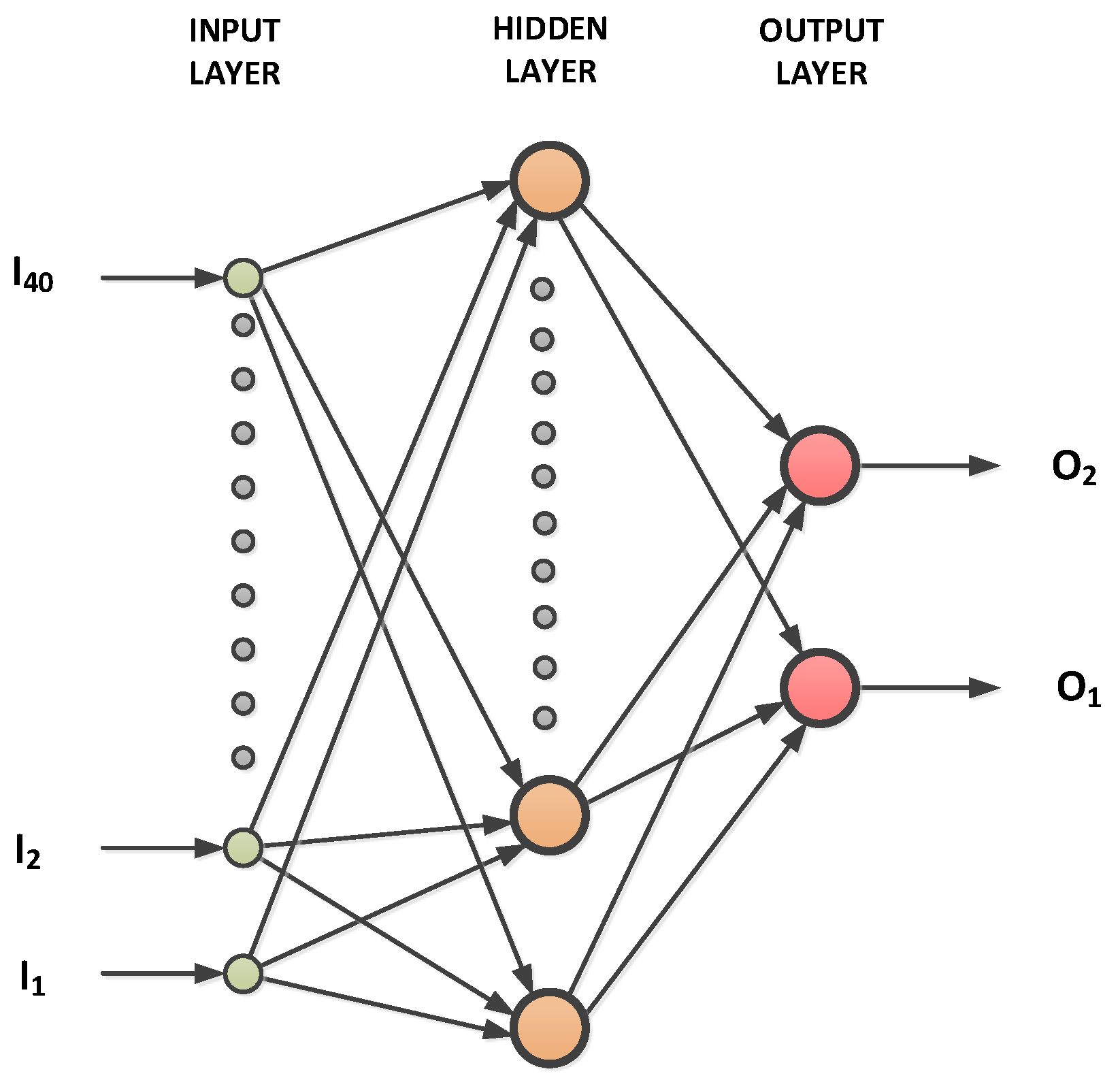
In the case under consideration, the unknown function that the ANN should learn is the shape of the hodograph as the input, and a sine and a cosine of the shaft position as the desired output of the network. A general view of the network structure that was used in the study is shown in Figure 2.
The examined network has the following topology: 40 inputs, 3 or 6 or 12 hidden layer neurons with s i g m o i d or r e l u activation function, and 2 output layer neurons with l i n e a r activation function. The network output determines the sine and cosine of the estimated position. The actual current hodograph (input vector I = [ I 1 , I 2 I 40 ] ) was given as input, and two elements vector O = [ O 1 , O 2 ] as output. The first element is the reference sine and the second the cosine of the shaft position. In order to obtain the current hodograph, an additional 500 Hz sinusoidal voltage was used in both axes α and β . A single hodograph frame (ANN input) contains 2 × 20 samples (for current axis α and current axis β , respectively). As a result, a new dataset (new current hodograph) is provided every 2 ms. In general, the hodograph can be interpreted as a two-dimensional shape on a plane. In the present approach, however, the hodograph is transformed into a one-dimensional vector (shape 1 × 40 ). The hodograph is, thus, treated as a point in a multi-dimensional (40-dimensional) space. The obtained measurement data are pre-processed. Input frames are filtered, scaled, and synchronized. Each data frame has a constant component removed, and its range of changes is scaled with a common function for both components of the axes α and β . The input data are scaled to the range ± 1 . Proper timing is important in the case of a one-dimensional data vector that has its beginning and an end, and should go to the ANN’s input in the right order. Synchronization is realized by the circular shift of both vectors α and β of the hodograph frame. Both axes are rotated by the same unit numbers to obtain the highest value in the β axis at the start of the data vector. This enables the correct coordinate order of a 40-dimensional point to be maintained when the HF mode needs to be switched on. The network training and calculations of the completed network are performed using P y t h o n 3 language and, more specifically, the K e r a s and T e n s o r F l o w packages. The algorithm of a position estimation consists of the following tasks:
  • Recording of high-frequency currents.
  • Centering and scaling of the current hodograph.
  • Computing the ANN output (sine and cosine of estimated position).
  • Scaling the ANN output.
  • Improving the estimation.

3.3. Recording of High-Frequency Currents

During a special preliminary investigation, the magnetic circuit of motors was examined for nonlinearities and saturation impacts. An HF range from 100 Hz to 1 kHz, and amplitude of current no more than half of the nominal current were chosen. The investigated motor was supplied from a PWM inverter with HF voltage for each a b c phase, shifted 2 3 π . A low harmless voltage was chosen. This frequency is selected to be as high as possible above the first harmonic for maximum machine speed for this sensorless mode of operation, and as low as possible below the inverter carrier frequency. The amplitude of the HF voltage was selected so that the induced HF current had a low enough value to cause the least possible shaft vibrations, but its measurement was repeatable—with an appropriate signal-to-noise ratio. The selected results presented below are carried with f H F = 500 Hz, voltage amplitude equal 1.6 V, and a resulting current amplitude about 1.1 A. The second motor acted as a motion drive and provided constant (low) rotation speed.

3.4. Centering and Scaling of the Current Hodograph

The recorded 3-phase currents a b c are converted to the stationary α β coordinate system. Figure 3 shows a sample set of the recorded HF currents.
High frequency currents may contain a constant component, e.g., in the case of a rotating shaft. This is shown in Figure 3 on the left (this is not a shaft position, just the currents). The enlarged fragment of the current samples is visible on the right. The constant component is then removed: when all 20 sets of the specified hodograph nodes { i α j , i β j } ( j = 1 , 2 , . . . , 20 ) have been collected, the data is centered numerically by shifting, respectively, in the α and β axes by the mean of the minimum and maximum values in the given axis. Finally, the current amplitudes are scaled to unit length—both sets α and β have the same scaling factor.

3.5. Computing the ANN Output

A s h a l l o w network was used to create the model. The calculations were made using the K e r a s and T e n s o r F l o w libraries written in P y t h o n 3 . The ANN training procedure will be covered in Section 5. The network operates on previously prepared data: the data is centered and scaled to the range ± 1 . The network consists of one hidden layer with a number of nodes n e u r o n s _ 1 W (equal to { 3 , 6 , 12 } depending on the test) and an output layer with two outputs (estimated sine and estimated cosine of the shaft position). This can be written in the program as
model = Sequential()
model.add(Dense(neurons_1W, input_dim = (2 ∗ data_length),
   activation = ‘sigmoid’))
model.add(Dense(2)).
Using such a small network increases the chances of getting good generalization. Various activation functions of the hidden layer were tested. These were functions s i g m o i d :
sigmoid ( x ) = 1 1 + e x
and r e l u :
ReLU ( x ) = m a x ( x , 0 ) .
The activation function of the output layer was linear:
out ( x ) = x .
For the sake of the quality of network generalization, the aim was to try to minimize the number of network nodes. The variable d a t a _ l e n g t h represents the number of nodes making up the current hodograph (in this case, the number is equal to 20).

3.6. Scaling the ANN Output

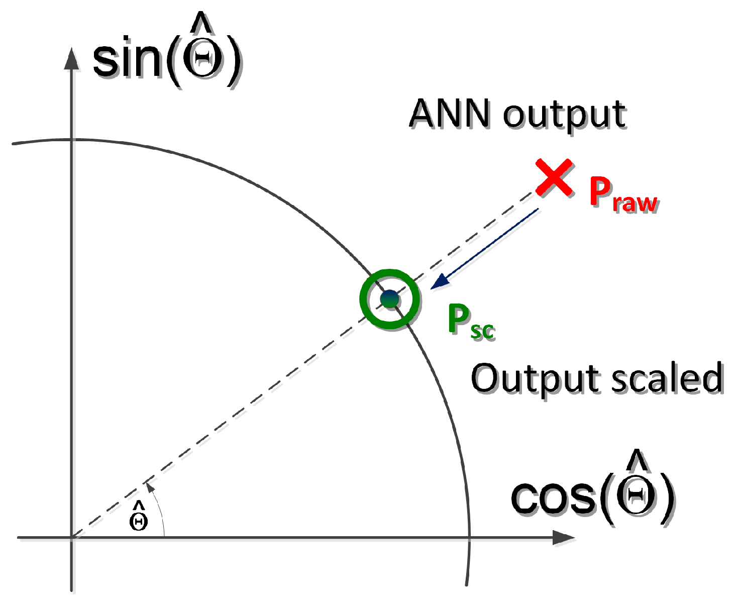
The sine and cosine values of the shaft position generated by the trained ANN do not always result in a vector of length one. Therefore, the paper proposes to modify the network output. The concept is shown in Figure 4.
The method works as follows: the ANN returns the values of c o s ( Θ ) ^ and s i n ( Θ ) ^ , which determines the point P r a w described by the coordinates { c o s ( Θ ) ^ , s i n ( Θ ) ^ } . It is assumed that an angle estimated by the ANN is correct. Vector P r a w is then scaled to the unit length—to the vector P s c ( s c —scaled). Based on the P s c vector, the corrected sine and cosine values of the estimated position Θ ^ can be determined.

3.7. Improving the Estimation

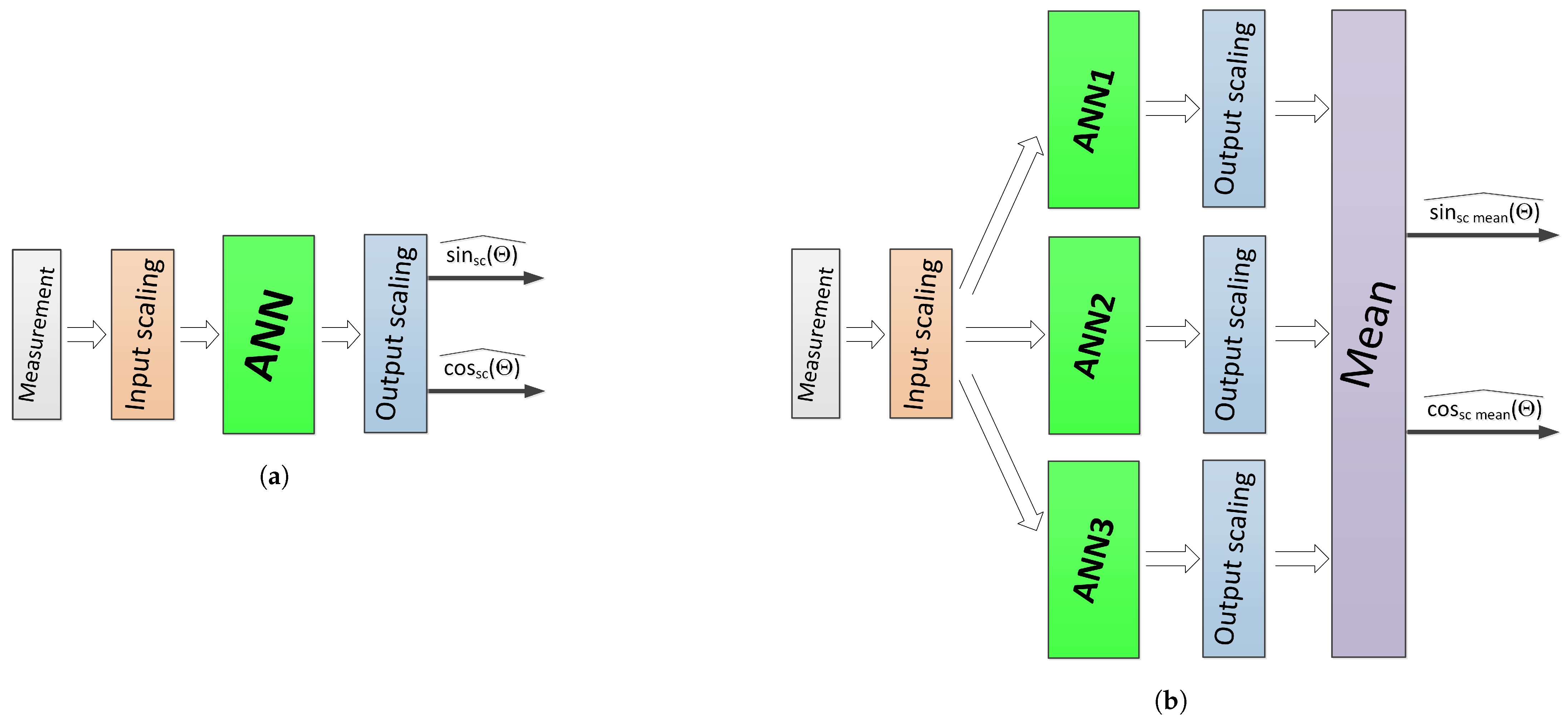
The trained network operates with a certain accuracy which cannot be improved with learning time due to the adverse effect of overfitting. In addition, due to the fact that the measurement data may include outliers and extreme outliers, and as the network is supposed to operate reliably on the available measurement quantities, it was decided to improve the quality of the network operation. Due to the random selection of initial network weights and, as a result, the different weight values obtained in the learning process, as well as due to the different set of training data at every training session, each trained network generates slightly different answers for the same input data. It was assumed that based on a group of responses from different networks processing the same data, a globally better quality of estimation can be obtained. Better quality was defined as a reduction in the number of outliers and a reduction in the mean error. The solution turned out to be a network of networks. Using the initial scaling treatment of the ANN output (Section 3.6), the reference method of the estimation process is shown in Figure 5a. The recorded data ( M e a s u r e m e n t block) are centered and scaled ( I n p u t s c a l i n g block) and then processed by the ANN. The network response, i.e., the estimated sine and cosine of the shaft position, are scaled to a unit length in the O u t p u t s c a l i n g block (output values c o s s c ( Θ ) ^ and s i n s c ( Θ ) ^ ). In the case of the modified estimator (Figure 5b), centered and scaled data are fed to the inputs of the network group (the same data to the inputs of all networks). These networks were trained on the same training sets. Each network’s response is scaled to unit length and then the total response is determined ( M e a n block). In the case of the presented solution, the best results were achieved by averaging the responses of all networks.

4. Laboratory Stand

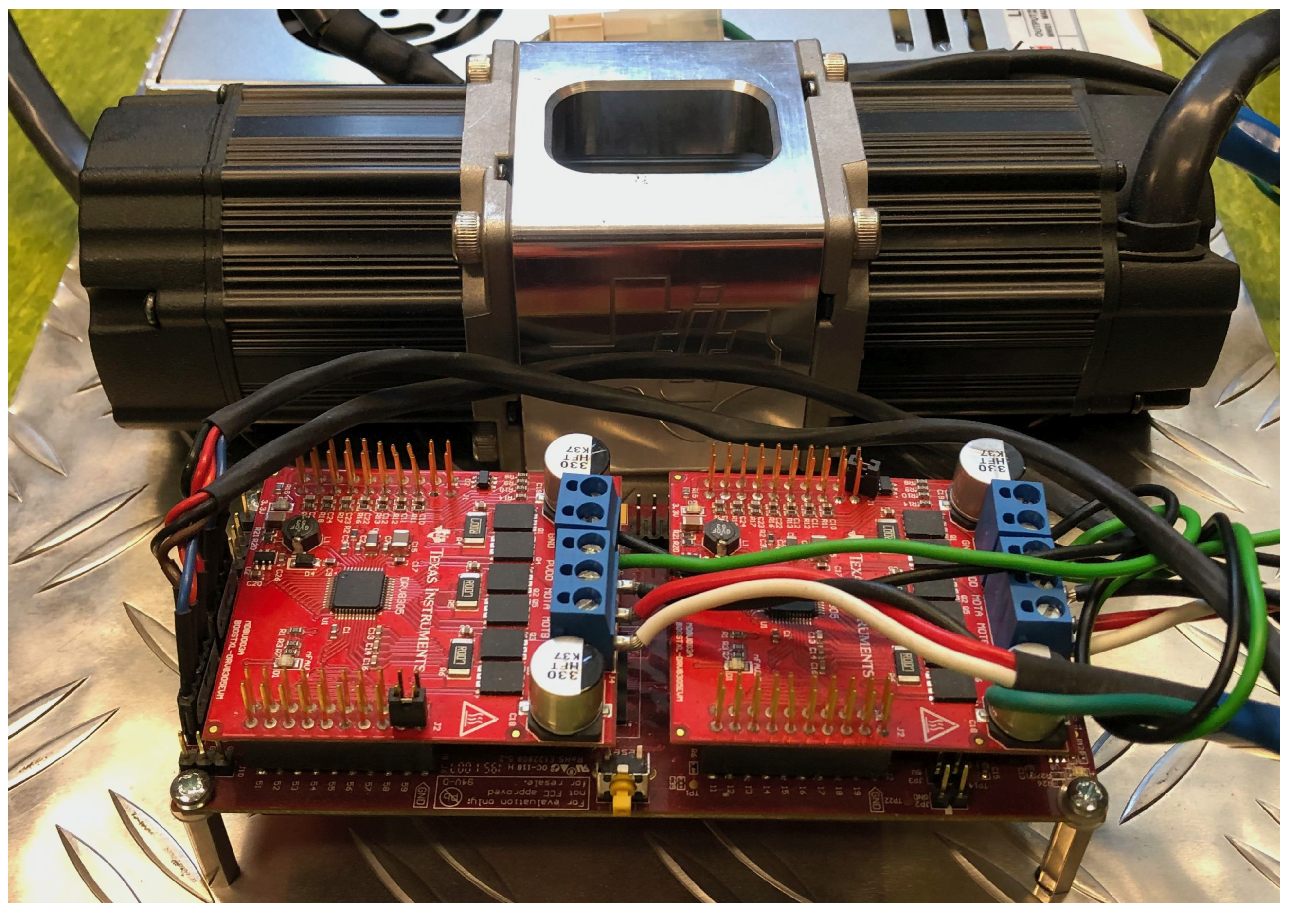
In order to experimentally verify the proposed estimation method, a laboratory bench was built. The setup allows double-sided operation within the desired speed and torque, and a few types of control. Control methods could be chosen with: pure PWM for each phase, SVM for 3-phase wiring, current control for each phase and α β reference frame, vector d q current control, torque control with or without a flux weakening region. For the results presented below the authors decided to treat one motor as the object of investigation and a second one as a low-speed driver. The setup is presented in Figure 6.
It consists of a pair of surface-mounted magnet synchronous motors, supplied separately from the three phase power MOSFET inverters. The control hardware consists of two main parts: a set of power electronics boards and real-time MCU. Texas Instruments Booster Packs Evaluation modules BOOSTXL-DRV8305 are used as power converters. They are complete 3-phase key independent control converters for small voltage operation, under 45 V with high current 20 A peak, including short circuit, thermal, shoot-through, and undervoltage protection. A Texas Instruments launchpad development kit LAUNCHXL-F28379D was used. This L a u n c h P a d is based on a superset dual-core, fast real-time co-processor Control Law Accelerator: F28379D device with onboard JTAG and USB. Control software was designed to experiment on fully independent control of both motors. The main structure of the used software was divided into two parts suitable for two independent motor control systems. The first unit was treated as an experimental structure for the presented algorithm testing, and the second as a load or shaft moving force. Few different structures were successfully implemented and tested. The presented programming control structure made it possible to build different structures, for example: a field-oriented motor controlled with high speed CLA current control, and a low-speed field voltage motor with high-frequency sinusoidal injection. The developed software structure provided any type of operation for both motors independently.
The mechanical part of the laboratory setup consist of twin low-voltage synchronous 3-phase PMSMs, inflexible coupling clip together with an aluminum frame. A Teknic M-2310P-LN-04K industrial grade NEMA 23 pair of motors characterized by fully sintered power materials, high-temperature Neodymium-Iron-Boron magnets, and an FEA (Finite Element Analysis) optimized stator is used. These properties provide natural PMSM characteristics under low voltage supply. Several special innovations were combined to provide more continuous motor performance. Oversize bearing reduced shaft friction influence. The both motors are also equipped with a 4000-pulses-per-revolution incremental encoders.
Catalogue of motor data:
  • R s = 0.72 Ω
  • L s = 0.40 mH
  • Ψ = 0.0443   V · s / rad
  • p o l e s = 8
  • V m a x = 40   V
  • ω n = 628 rad / s
  • T n = 0.274 Nm
  • I n = 7.1 A .

5. Results

As part of this study, the following experiments were carried out. The values of HF currents for shaft rotations in several independent sequences were recorded. At the same time, the position of the shaft (a sine and a cosine of the position) was recorded in order to validate the results. This was carried out with pauses between the individual data recording sequences with the purpose of diversifying the initial conditions of data recording, e.g., for different values of machine temperature, different initial shaft positions etc. Then, network training studies were carried out in various configurations, including changes in the training set, the number of neurons in hidden layers, and activation functions. Finally, using a trained network, position estimation tests were carried out on data for which the network was not trained. The illustrations shown in this section are experimental results based on laboratory bench measurements.

5.1. Input Data

The example sets of recorded and pre-processed data for the examined SPMSM are shown in Figure 7. The data is already processed, which consists in removing the constant component and scaling.
To keep the image clear, only three frames are drawn (Figure 7a). It can be seen that for three such different shaft positions (rotated every 120 degrees), it is difficult to see the relationship between the shape of the hodograph and the position of the shaft. The path is not closed but has a beginning and an end. This is due to data synchronization of the input vector for ANN processing. The 3D visualization of recorded current hodographs is shown in Figure 7b. In the vertical axis, the angle changes in the range of one full revolution of the motor shaft (electrical angle).

5.2. ANN Calculation

The ANN training was carried out using the P y t h o n 3 language. Due to the nature of this task, i.e., optimization, use of a SPMD (Single Program, Multiple Data) approach enables easy parallelization of calculations using the m u l t i p r o c e s s i n g package. This package allows one to commission many independent optimization tasks at one time. The key instruction, e.g.,
multiprocessing.Pool
distributes the tasks to available processors. In order to carry out the network training process and verify its performance, ten datasets were prepared. Each one includes at least one complete electrical revolution of the motor shaft. These data were combined into a series of training samples in several combinations, e.g.,
big_set#1 = set#1 + set#2 + ,..., + set#10 
big_set#2 = set#10 + set#9 + ,..., + set#1
and other randomly mixed sets. In order to determine roughly the network training parameters, such as the number of learning epochs, the selection of the best training data vector sequence ( b i g _ s e t # vectors), and the determination of the b a t c h _ s i z e and l e a r n i n g _ r a t e parameters, several hundred trial training series were carried out. Repeatedly performed tests showed that the number of positively qualified training results does not depend significantly on the training set. It may be proof of correctly performed data registration, without a large amount of outliers (input outliers were not rejected/modified in the data preparation process). Then, each b i g _ s e t was divided into two parts: training and testing (Figure 8).
Thus,  510 sets of samples (every sample is understood as a current hodograph) were used as a training set. It was then divided into two halves with randomly selected samples: a training and a validation set. The remaining 510 samples were not used in the training and validation process. They were only used in the finished ANN tests (part of Figure 8 marked as t e s t i n g ). Although Figure 8 shows the data of the training sets, the results of the trained network are also shown. The meaning of these quantities will be explained in more detail in the following figures. The ANN tests performed showed that the best results were obtained when using the sigmoid activation function. Dropout rate was tested in the range 0–0.5; however, for the presented task, the network worked best without the dropout layer. The most effective network contained six neurons in the hidden layer, although there were well-functioning networks for three neurons in the hidden layer. The worst quality indexes were obtained for 12 neurons in the hidden layer. Figure 9 shows the results that confirm the correct operation of the ANN in the case of a single rotation of the motor shaft.
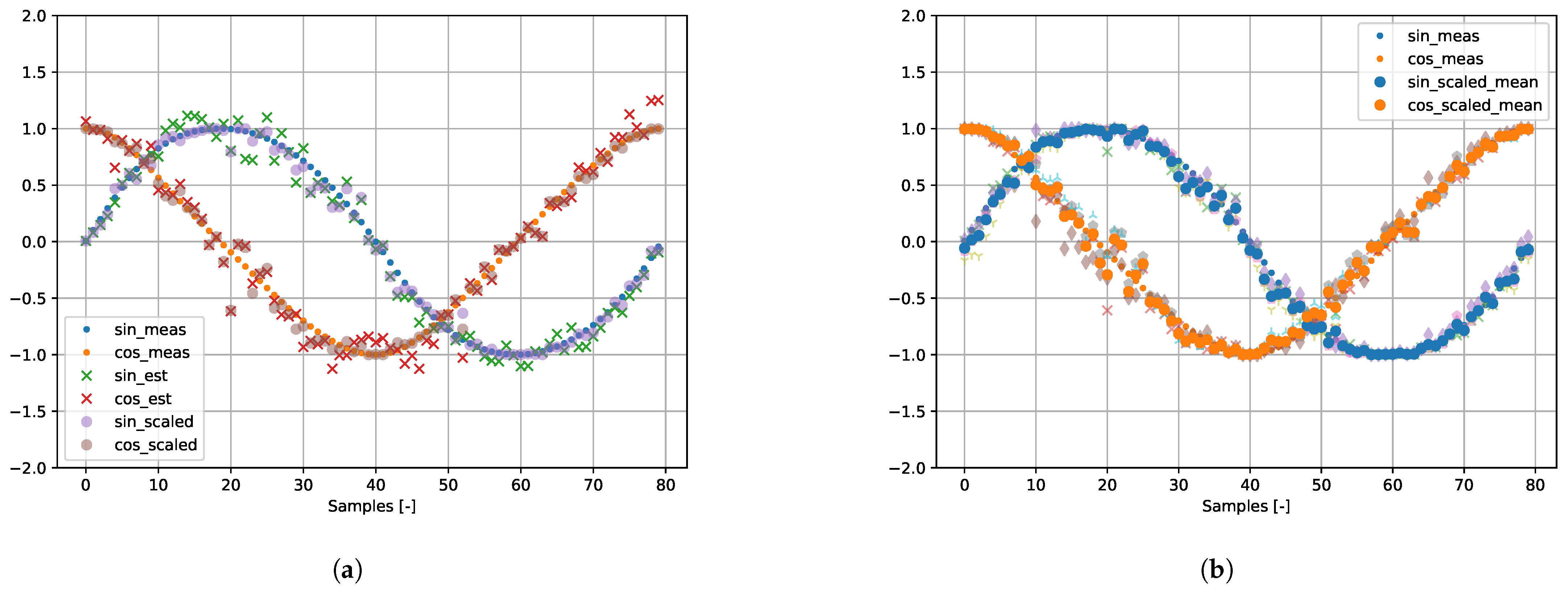
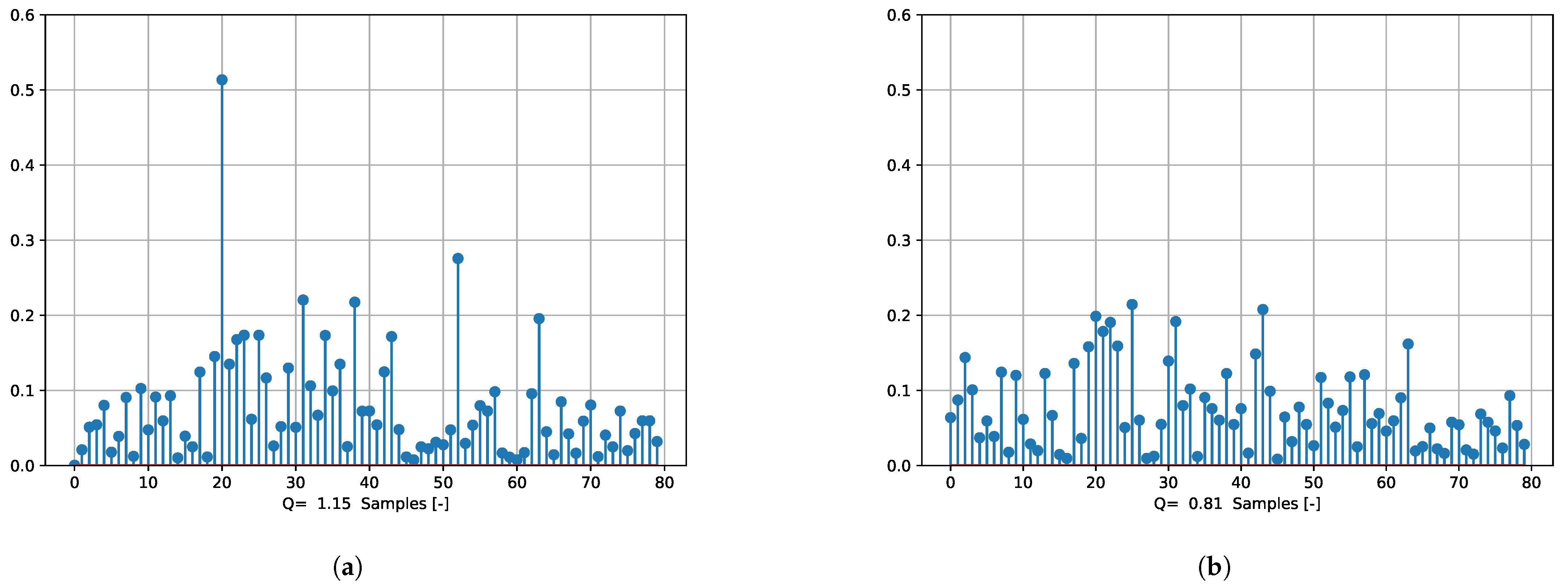
The results of the operation of a single network (selected ANN#1—one of the components of the multiple ANN) and the results of multiple ANNs, the superior network operation, are presented. A complete dataset over a single test cycle contains 102 samples. One complete revolution equals 80 samples (80 current hodographs)—meaning that more than one rotation is stored. It is organized in this way due to memory usage of the hardware. The five datasets were used to train the network, while the following five were used for testing. The sine and cosine values marked with m e a s are training and measurement data. The values marked with e s t are the ANN’s output—estimated position. It is visible that the vector determined by the estimated values of the position’s trigonometric functions is not of unit length. Only after processing these quantities—scaling—do the values of estimated sines and cosines become values lying on a unit circle. Those values are marked as s c a l e d . In the case of multiple ANNs, a s c a l e d _ m e a n denotes the ANN’s output, after scaling and averaging. It can be seen that the extreme outliers, although visible in the responses of the component networks, are clearly smaller in the response of the multiple ANN (Figure 9). This phenomenon is more visible in Figure 10 showing the error values. These figures show the error that is computed as the larger value of the sine or cosine estimation errors. The waveforms in Figure 10 correspond to those in Figure 9. It can be seen that the extreme outlier (sample #20) from Figure 10a is reduced (Figure 10b). Furthermore, other outliers (e.g., samples #52, #63) are significantly reduced. This applies in principle to the rest of the samples. The presented data was described with the value of the quality index. This index is determined as the sum of squared values of the error for the position estimation for all n samples:
Q = i = 1 n sin ( Θ ) i sin s c ( Θ ) i ^ 2 + cos ( Θ ) i cos s c ( Θ ) i ^ 2
where sin ( Θ ) and cos ( Θ ) are the sine and cosine of the real (measured) position, sin s c ( Θ ) ^ and cos s c ( Θ ) ^ are estimated and scaled (Figure 4) values of the position’s sine and cosine. There is a clear reduction in the quality index: Q = 1.15 vs Q = 0.81 , approximately 30%. The analysis was then repeated for all available samples for the untrained data (in the dataset for the combined data from several shaft revolutions). Now, a complete dataset over a few test cycles contains 510 samples. Figure 11 shows the results that confirm the correct operation of the ANN in the case of multiple shaft rotations of the motor shaft.
The description of signals in Figure 11 corresponds to those in Figure 9. For a larger range of recorded current hodographs, it is clear that in the presence of extreme outliers, the multi-network enables the reduction of the position estimation error. Figure 11 shows how in some datasets containing extreme outliers, the unscaled responses of networks may contain errors, which can nevertheless be significantly reduced. This is achieved by scaling and using multiple networks that process the same input. Figure 12 shows the error values. The waveforms in Figure 12 correspond to those in Figure 11. One can observe extreme outlier reduction for multiple networks. At this stage of the research, the reduction of (ANN) input outliers was not an issue. Furthermore, the quality index was significantly reduced, from Q = 18.14 to Q = 14.21 , i.e., by nearly 22%. Summarizing the research carried out, the distribution of obtained data (estimator outputs) was displayed. Figure 13 shows the spread and centers of the obtained datasets using boxplot.
The results obtained for a selected (single) ANN and a set of cooperating networks ( M u l t i p l e A N N ) are presented. Figure 13a shows a direct comparison of S i n g l e A N N vs. M u l t i p l e A N N in the case of a single shaft rotation, with reference to the data corresponding to those in Figure 9. Figure 13b shows a direct comparison of S i n g l e A N N vs. M u l t i p l e A N N for all available shaft rotation data, with reference to the data corresponding to those in Figure 11. Figure 13c shows the enlarged area in Figure 13b. In all cases, one can notice a reduction in outliers for the M u l t i p l e A N N estimator.
Table 1 presents a summary of the quality index values for individual component ANNs and for the operation of the entire M u l t i p l e A N N .
The Q u a l i t y i n d e x is defined by Formula (9). The M a x . e r r o r indicates extreme outliers (Figure 12). All the errors are recorded as the greater error value from both the sine and cosine estimations for the specified position. The resulting data can be interpreted as the synergy result of a sample set of four trained networks, analyzed for all available data, for which the network was not trained. It can be seen that the quality index for cooperating networks has a value significantly lower ( Q = 14.2 ) than the lowest quality index value for networks operating individually ( Q = 17.2 ). It is worth noticing that to achieve such a good effect, the network response errors should be canceled out. This requires checking the various combinations of the ANN sets obtained during the training.

6. Conclusions

This paper provides a method for estimating the shaft position for SPMSM drive in the case of a standstill or very low speed operation. The proposed method includes using ANNs to estimate the position of the motor shaft through high-frequency currents induced by an additional test voltage. Despite the assumed magnetically symmetrical structure of the machine, due to mechanical imperfections, the ANN has the ability to recognize the shape of the current hodograph and associate it with the position of the shaft. Such a system can also work with a salient motor. The main advantage of such a physical position estimation method is the ability to get the response almost immediately without a transients, as is for example the case with position estimation using observers, who reach a steady state after a certain amount of time.
In terms of linking the shape of the current hodograph with the values of the sine and cosine of the shaft position, the most effective network contained six neurons in the hidden layer, with sigmoid activation function and no dropout.
A set of ANNs that perform calculations on the basis of the same input data was used as an estimator. Since each network has been trained independently, they generate slightly different responses for the same input signals. Proper processing of the set of these responses (in this case, scaling and mean) enables the quality of the position estimation to be improved. Using such an estimator, an improvement in the quality index was achieved approximately 22% in the group of all test data.
The amplitude and frequency of the additional HF voltage should be appropriately selected so as not to induce excessive currents and not to excite vibrations of the motor shaft.

Author Contributions

Conceptualization, K.U. and D.J.; Investigation, K.U. and D.J.; Methodology, K.U. and D.J.; Hardware and data recording, D.J.; ANN training and processing, K.U.; Software, K.U. and D.J.; Validation, K.U. and D.J.; Writing—review and editing, K.U. and D.J. All authors have read and agreed to the published version of the manuscript.

Funding

This research was financially supported as a statutory work of Poznan University of Technology (No. 0214/SBAD/0221).

Conflicts of Interest

The authors declare no conflict of interest.

Abbreviations

The following abbreviations are used in this manuscript:
ANNArtificial Neural Network
BEMFBack Electromotive Force
BPFBand-Pass Filter
BSFBand-Stop Filter
FOCField-Oriented Control
PMSMPermanent Magnet Synchronous Motor

References

  1. Liu, K.; Zhang, Q.; Chen, J.; Zhu, Z.Q.; Zhang, J. Online Multiparameter Estimation of Nonsalient-Pole PM Synchronous Machines With Temperature Variation Tracking. IEEE Trans. Ind. Electron. 2011, 58, 1776–1788. [Google Scholar] [CrossRef] [Green Version]
  2. Moreau, S.; Kahoul, R.; Louis, J.P. Parameters estimation of permanent magnet synchronous machine without adding extra-signal as input excitation. In Proceedings of the Industrial Electronics, 2004 IEEE International Symposium on IEEE, Ajaccio, France, 4–7 May 2004; Volume 1, pp. 371–376. [Google Scholar]
  3. Parasiliti, F.; Petrella, R.; Tursini, M. Sensorless Speed Control of a PM Synchronous Motor Based on Sliding Mode Observer and Extended Kalman Filter; IEEE: Chicago, IL, USA, 2001; Volume 1, pp. 533–540. [Google Scholar] [CrossRef]
  4. Baek, S.W.; Lee, S.W. Design Optimization and Experimental Verification of Permanent Magnet Synchronous Motor Used in Electric Compressors in Electric Vehicles. Appl. Sci. 2020, 10, 3235. [Google Scholar] [CrossRef]
  5. Qiu, Z.; Chen, Y.; Lin, X.; Cheng, H.; Kang, Y.; Liu, X. Hybrid Carrier Frequency Modulation Based on Rotor Position to Reduce Sideband Vibro-Acoustics in PMSM Used by Electric Vehicles. World Electr. Veh. J. 2021, 12, 100. [Google Scholar] [CrossRef]
  6. Łebkowski, A. Design, Analysis of the Location and Materials of Neodymium Magnets on the Torque and Power of In-Wheel External Rotor PMSM for Electric Vehicles. Energies 2018, 11, 2293. [Google Scholar] [CrossRef] [Green Version]
  7. Gao, H.; Zhang, W.; Wang, Y.; Chen, Z. Fault-Tolerant Control Strategy for 12-Phase Permanent Magnet Synchronous Motor. Energies 2019, 12, 3462. [Google Scholar] [CrossRef] [Green Version]
  8. Hezzi, A.; Ben Elghali, S.; Bensalem, Y.; Zhou, Z.; Benbouzid, M.; Abdelkrim, M.N. ADRC-Based Robust and Resilient Control of a 5-Phase PMSM Driven Electric Vehicle. Machines 2020, 8, 17. [Google Scholar] [CrossRef]
  9. Wisniewski, J.; Koczara, W. Control of Axial Flux Permanent Magnet Motor by the PIPCRM method at standstill and at low speed. In Proceedings of the Power Electronics and Motion Control Conference, EPE-PEMC 2008, 13th, Poznań, Poland, 1–3 September 2008; pp. 2254–2260. [Google Scholar]
  10. Janiszewski, D. Load Torque Estimation for sensorless PMSM drive with output filter fed by PWM converter. In Proceedings of the 39th Annual Conference of the IEEE Industrial Electronics Society (IECON 2013), Vienna, Austria, 10–13 November 2013; pp. 2953–2959. [Google Scholar]
  11. Seilmeier, M.; Ebersberger, S.; Piepenbreier, B. PMSM model for sensorless control considering saturation induced secondary saliencies. In Proceedings of the 2013 IEEE International Symposium on Sensorless Control for Electrical Drives and Predictive Control of Electrical Drives and Power Electronics (SLED/PRECEDE), Munich, Germany, 17–19 October 2013; pp. 1–8. [Google Scholar] [CrossRef]
  12. Quang, N.; Ha, Q.; Hieu, N. FPGA sensorless PMSM drive with adaptive fading extended Kalman filtering. In Proceedings of the 2014 13th International Conference on Control Automation Robotics Vision (ICARCV), Singapore, 10–12 December 2014; pp. 295–300. [Google Scholar] [CrossRef]
  13. Fernandes, E.; Oliveira, A.; Vitorino, M.; dos Santos, E.; Santos, W. Speed sensorless PMSM motor drive system based on four-switch three-phase converter. In Proceedings of the IECON 2014—40th Annual Conference of the IEEE Industrial Electronics Society, Dallas, TX, USA, 29 October–1 November 2014; pp. 902–906. [Google Scholar] [CrossRef]
  14. Xu, P.; Zhu, Z. Analysis of carrier signal injection based sensorless control of PMSM drives under limited inverter switching frequency condition. In Proceedings of the 2014 IEEE Energy Conversion Congress and Exposition (ECCE), Pittsburgh, PA, USA, 14–18 September 2014; pp. 4131–4138. [Google Scholar] [CrossRef]
  15. Benevieri, A.; Marchesoni, M.; Passalacqua, M.; Vaccaro, L. Experimental Low-Speed Performance Evaluation of Sensorless Passive Algorithms for SPMSM. IEEE Trans. Energy Convers. 2021. [Google Scholar] [CrossRef]
  16. Yoo, J.; Sul, S.K. Stability Analysis of PI-Controller-Type Position Estimator for Sensorless PMSM Drives in Flux Weakening Region. In Proceedings of the 2021 IEEE Transportation Electrification Conference & Expo (ITEC), Chicago, IL, USA, 21–25 June 2021; pp. 434–438. [Google Scholar] [CrossRef]
  17. Wang, Z.; Lu, Q.; Ye, Y.; Lu, K.; Fang, Y. Investigation of PMSM Back-EMF Using Sensorless Control with Parameter Variations and Measurement Errors. Prz. Elektrotech. 2012, 88, 182–186. [Google Scholar]
  18. Hamida, M.; De Leon, J.; Glumineau, A.; Boisliveau, R. An Adaptive Interconnected Observer for Sensorless Control of PM Synchronous Motors With Online Parameter Identification. IEEE Trans. Ind. Electron. 2013, 60, 739–748. [Google Scholar] [CrossRef]
  19. Nair, S.V.; Hatua, K.; Prasad, N.V.P.R.D.; Reddy, D.K. A Quick I-f Starting of PMSM Drive With Pole Slipping Prevention and Reduced Speed Oscillations. IEEE Trans. Ind. Electron. 2021, 68, 6650–6661. [Google Scholar] [CrossRef]
  20. Corley, M.J.; Lorenz, R.D. Rotor position and velocity estimation for a salient-pole permanent magnet synchronous machine at standstill and high speeds. IEEE Trans. Ind. Appl. 1998, 34, 784–789. [Google Scholar] [CrossRef]
  21. Schroedl, M. Sensorless control of AC machines at low speed and standstill based on the “INFORM” method. In Proceedings of the Conference Record of the 1996 IEEE Industry Applications Conference, Thirty-First IAS Annual Meeting, IAS ’96, San Diego, CA, USA, 6–10 October 1996; Volume 1, pp. 270–277. [Google Scholar] [CrossRef]
  22. Zentai, A.; Daboczi, T. Improving INFORM calculation method on permanent magnet synchronous machines. In Proceedings of the IEEE Instrumentation and Measurement Technology Conference Proceedings, IMTC 2007, Warsaw, Poland, 1–3 May 2007; pp. 1–6. [Google Scholar] [CrossRef]
  23. Scicluna, K.; Staines, C.S.; Raute, R. Sensorless Low/Zero Speed Estimation for Permanent Magnet Synchronous Machine Using a Search-Based Real-Time Commissioning Method. IEEE Trans. Ind. Electron. 2020, 67, 6010–6018. [Google Scholar] [CrossRef]
  24. Abry, F.; Zgorski, A.; Lin-Shi, X.; Retif, J.M. Sensorless position control for SPMSM at zero speed and acceleration. In Proceedings of the 2011—14th European Conference on Power Electronics and Applications (EPE 2011), Birmingham, UK, 30 August–1 September 2011; pp. 1–9. [Google Scholar]
  25. Pando-Acedo, J.; Romero-Cadaval, E.; Milanes-Montero, M.I.; Barrero-Gonzalez, F. Improvements on a Sensorless Scheme for a Surface-Mounted Permanent Magnet Synchronous Motor Using Very Low Voltage Injection. Energies 2020, 13, 2732. [Google Scholar] [CrossRef]
  26. Ilioudis, V.C. Sensorless Control of Permanent Magnet Synchronous Machine with Magnetic Saliency Tracking Based on Voltage Signal Injection. Machines 2020, 8, 14. [Google Scholar] [CrossRef] [Green Version]
  27. Pillay, P.; Krishnan, R. Modeling, simulation, and analysis of permanent-magnet motor drives. I. The permanent-magnet synchronous motor drive. IEEE Trans. Ind. Appl. 1989, 25, 265–273. [Google Scholar] [CrossRef]
  28. Szabat, K.; Wróbel, K.; Dróżdż, K.; Janiszewski, D.; Pajchrowski, T.; Wójcik, A. A Fuzzy Unscented Kalman Filter in the Adaptive Control System of a Drive System with a Flexible Joint. Energies 2020, 13, 2056. [Google Scholar] [CrossRef] [Green Version]
  29. Urbanski, K.; Janiszewski, D. Sensorless Control of the Permanent Magnet Synchronous Motor. Sensors 2019, 19, 3546. [Google Scholar] [CrossRef] [Green Version]
  30. Nicola, M.; Nicola, C.I. Sensorless Fractional Order Control of PMSM Based on Synergetic and Sliding Mode Controllers. Electronics 2020, 9, 1494. [Google Scholar] [CrossRef]
  31. Vas, P. Sensorless Vector and Direct Torque Control; Number 42 in Monographs in Electrical and Electronic Engineering; Oxford University Press: Oxford, UK; New York, NY, USA, 1998. [Google Scholar]
  32. Malinowski, M.; Kazmierkowski, M.; Trzynadlowski, A. A comparative study of control techniques for PWM rectifiers in AC adjustable speed drives. IEEE Trans. Power Electron. 2003, 18, 1390–1396. [Google Scholar] [CrossRef]
  33. Brock, S. Analysis and Simulation of Electrical and Computer Systems; Chapter Robust Integral Sliding Mode Tracking Control of a Servo Drives with Reference Trajectory Generator; Springer International Publishing: Cham, Switzerland, 2015; pp. 305–313. [Google Scholar] [CrossRef]
  34. Kazmierkowski, M.; Franquelo, L.; Rodriguez, J.; Perez, M.; Leon, J. High-Performance Motor Drives. IEEE Ind. Electron. Mag. 2011, 5, 6–26. [Google Scholar] [CrossRef] [Green Version]
  35. Urbanski, K.; Majchrzak, D. Faults detection in PMSM drive using Artificial Neural Network. Prz. Elektrotech. 2017, 1, 22–25. [Google Scholar] [CrossRef] [Green Version]
  36. Sinha, A.K.; Kumar, P.; Hati, A.S. ANN Based Fault Detection Scheme for Bearing Condition Monitoring in SRIMs using FFT, DWT and Band-pass Filters. In Proceedings of the 2020 International Conference on Power, Instrumentation, Control and Computing (PICC), Thrissur, India, 17–19 December 2020; pp. 1–6. [Google Scholar] [CrossRef]
  37. Li, S.; Won, H.; Fu, X.; Fairbank, M.; Wunsch, D.C.; Alonso, E. Neural-Network Vector Controller for Permanent-Magnet Synchronous Motor Drives: Simulated and Hardware-Validated Results. IEEE Trans. Cybern. 2020, 50, 3218–3230. [Google Scholar] [CrossRef]
  38. Yao, C.; Sun, Z.; Xu, S.; Zhang, H.; Ren, G.; Ma, G. Optimal Parameters Design for Model Predictive Control using an Artificial Neural Network Optimized by Genetic Algorithm. In Proceedings of the 2021 13th International Symposium on Linear Drives for Industry Applications (LDIA), Wuhan, China, 1–3 July 2021; pp. 1–6. [Google Scholar] [CrossRef]
  39. Ramírez-Cárdenas, O.D.; Trujillo-Romero, F. Sensorless Speed Tracking of a Brushless DC Motor Using a Neural Network. Math. Comput. Appl. 2020, 25, 57. [Google Scholar] [CrossRef]
  40. Urbanski, K. Position Estimation at Zero Speed for PMSM Using Probabilistic Neural Network. In Proceedings of the 2015 IEEE 2nd International Conference on Cybernetics (Cybconf), Gdynia, Poland, 24–26 June 2015; pp. 427–432. [Google Scholar]
  41. Park, G.; Kim, G.; Gu, B.G. Sensorless PMSM Drive Inductance Estimation Based on a Data-Driven Approach. Electronics 2021, 10, 791. [Google Scholar] [CrossRef]
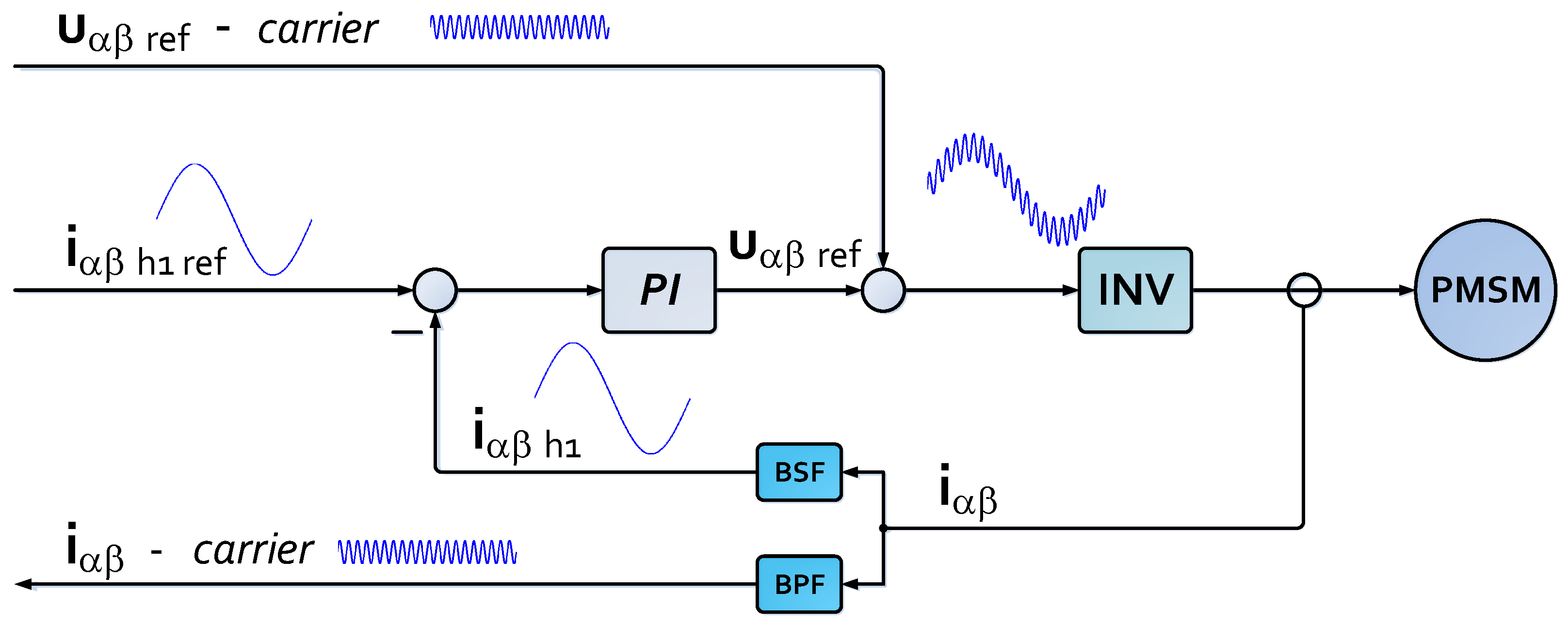
Figure 1. General view of the injecting carrier signal excitation scheme for sensorless PMSM as the quasi 2-dimensional α β control layers.
Energies 14 08134 g001
Figure 2. General view of used ANN structure.
Energies 14 08134 g002
Figure 3. General view of raw data used in the process. (Left): full set #1 of currents in the α -axis and β -axis, which are used to build the hodograph after preprocessing. (Right): an enlarged fragment of this set. HF current: f = 500 Hz. Data collected during the slow rotation of the motor shaft. Currents related to nominal value [pu].
Energies 14 08134 g003
Figure 4. Visualization of the concept of scaling the data generated by ANN.
Energies 14 08134 g004
Figure 5. Visualization of the concept of estimation improvement: (a) Base system using a single ANN. (b) Modification based on using multiple ANNs. In order to get a clear picture, only three ANNs have been used here.
Energies 14 08134 g005
Figure 6. General view of the key components of the laboratory bench.
Energies 14 08134 g006
Figure 7. Experiment: the current hodograph for the examined machine. (a) Three frames every 120 degrees, normalized current. (b) 3D hodograph for data recorded in the laboratory. Full data record, some of which are shown in Figure 7a.
Energies 14 08134 g007
Figure 8. Division of data into training, validation, and testing.
Energies 14 08134 g008
Figure 9. Single shaft rotation (electric angle), sine, and cosine of shaft position. (a) Using a single ANN. (b) Using multiple ANNs. Visible (not labeled) scaled responses of all used ANNs.
Energies 14 08134 g009
Figure 10. Single shaft rotation (electric angle), sine, and cosine estimation error. (a) Using a single ANN. (b) Using multiple ANNs.
Energies 14 08134 g010
Figure 11. Multiple shaft rotations (electric angle), sine, and cosine of shaft position. (a) Using a single ANN. (b) Using multiple ANNs. It can be seen that in this case the estimated points lie closer to the corresponding measured values.
Energies 14 08134 g011
Figure 12. Multiple shaft rotations (electric angle), sine, and cosine estimation error. (a) Using a single ANN. (b) Using multiple ANNs.
Energies 14 08134 g012
Figure 13. Experimental results—open-loop system verification, boxplot view of estimation error. (a) In case of a single rotation. (b) In case of multiple rotations. (c) Enlarged view from Figure 13b.
Energies 14 08134 g013
Table 1. Sample results for the presented set of trained networks.
ANN#1ANN#2ANN#3ANN#4Multi-ANN
Quality index18.119.217.218.814.2
Max. error21.051.781.441.52
Publisher’s Note: MDPI stays neutral with regard to jurisdictional claims in published maps and institutional affiliations.