Article

Integration of Electric Vehicles and Energy Storage System in Home Energy Management System with Home to Grid Capability

1
Department of Electrical Engineering, Zakir Husain College of Engineering and Technology, Aligarh Muslim University, Aligarh 202002, India
2
Industrial Engineering Department, College of Engineering, King Saud University, Riyadh 11421, Saudi Arabia
3
School of Science, College of Sciences, Technology, Engineering, Mathematics, RMIT University, Melbourne, VIC 3001, Australia
*
Authors to whom correspondence should be addressed.
Energies 2021, 14(24), 8557; https://doi.org/10.3390/en14248557
Submission received: 4 November 2021 / Revised: 28 November 2021 / Accepted: 14 December 2021 / Published: 18 December 2021

Abstract

:
In this paper, we proposed a home energy management system (HEMS) that includes photovoltaic (PV), electric vehicle (EV), and energy storage systems (ESS). The proposed HEMS fully utilizes the PV power in operating domestic appliances and charging EV/ESS. The surplus power is fed back to the grid to achieve economic benefits. A novel charging and discharging scheme of EV/ESS is presented to minimize the energy cost, control the maximum load demand, increase the battery life, and satisfy the user’s-traveling needs. The EV/ESS charges during low pricing periods and discharges in high pricing periods. In the proposed method, a multi-objective problem is formulated, which simultaneously minimizes the energy cost, peak to average ratio (PAR), and customer dissatisfaction. The multi-objective optimization is solved using binary particle swarm optimization (BPSO). The results clearly show that it minimizes the operating cost from 402.89 cents to 191.46 cents, so that a reduction of 52.47% is obtained. Moreover, it reduces the PAR and discomfort index by 15.11% and 16.67%, respectively, in a 24 h time span. Furthermore, the home has home to grid (H2G) capability as it sells the surplus energy, and the total cost is further reduced by 29.41%.

1. Introduction

Energy demand increases very sharply day by day. To overcome this problem and optimize the power generated, researchers have proposed an effective strategy called DSM [1]. In DSM, the demand has been controlled by the consumers from the demand side [2]. It includes market price control strategies, DR programs, optimal utilization of RES, etc. DR programs encourage the consumers to manage their power utilities in response to pricing signals [3]. A significant advantage of DR programs is that they are free from environmental issues and financial burden [4]. Consumers may shift their domestic appliances usage from peak hour to off-peak hour to achieve economic benefits. To achieve the benefits of DR programs, a HEMS is required at home. The HEMS optimally schedules domestic usage to reduce electricity bills. Moreover, HEMS increases consumer comfort, reduces peak-to-average ratio (PAR), and minimizes the burden on the grid.
Several HEMS strategies have been proposed in the literature. In [5], a HEMS system has been proposed to schedule domestic appliances in response to RTP. They formulate a multi-objective optimization problem that considers bill minimization and user comfort as system objectives. ELPSO has been used to find optimal values. In [6], an optimization-based HEMS controller is proposed, which minimizes the electricity bill while maintaining the user’s comfort. Power and thermal set values have been considered as system constraints. They have considered a large set of appliances, including schedulable, thermal, and critical ones. The optimization problem has been solved using MILP.
Optimum scheduling of home appliances in an off-peak period may increase the peak-to-average ratio, which increases the burden on power utility and causes grid failure. To handle the problem of overloading, some researchers have considered PAR as one of the objectives or constraints in optimization problems [7,8,9]. In [7], an excellent scheduling strategy for household electricity usage was proposed. The home gateway takes DR information, which includes pricing, utility generation, and load information and then transfers it to an EMC. The EMC produces an optimum power scheduling system using the DR. As a result, all home appliances run automatically and efficiently. Using only the RTP model, most appliances may run at the cheapest times of day, possibly damaging the entire electric grid. Their study combines RTP with the IBR model. Using this integrated pricing model, the suggested power scheduling strategy reduces both energy costs and PAR, improving the overall system stability. They employ a GA to address optimization problems.
In [10], the authors specifically deploy the system in combination with multiple TOU prices to demonstrate the optimization algorithm’s benefits in reducing consumption peak and power cost. This would also encourage people to change how they use their appliances and choose the tariff that best matches their consumption flexibility. The algorithm may also restrict the operation of programmable appliances during high-rate time intervals, resulting in further savings for those with greater flexibility.
In [11], the authors proposed a HEMS that considers energy cost, PAR, and user comfort as their objectives in the multi-objective problem. They have optimized the different objectives using MINLP. RES with ESS increases the capability of HEMS, in order to reduce the power purchased from the grid, and improves PAR. This research provides a generic architecture for a HEMS and a multi-restricted scheduling method for residential consumers. The optimization issue is constructed using the TOU pricing method. This study optimizes the issue using a powerful meta-heuristic known as the GWO. The GWO approach outperforms the PSO algorithm. A PV system on the building’s roof is connected to the system to show the appliances’ cost-effectiveness. In [12], the integration of RES with HEMS was presented to reduce the peak demand and increase the stability of the power grid. They utilized the RES and scheduled domestic appliances to reduce the PAR, power purchased, and electricity bill. In [13], the authors presented an energy management strategy for a remote and off-grid home with the integration of RES. They demonstrated the acceptability of RES in a remote, isolated island.
In [14], an architecture for HEMS was designed that efficiently utilized energy output from locally accessible renewable sources by gradually switching electric appliances. Renewable energy generation is limited in some situations without HEMS, such as when batteries are completely charged, even under favorable weather conditions. HEMS’s fuzzy rules reduce RES generation curtailment by providing high-power non-traditional storage alternatives. It presents a numerical case study of a renewable energy system in Hulubești, Romania.
The integration of ESS and EV increases the capability of HEMS. EV with the V2H and V2G capabilities provides extra financial benefits to consumers. They supply power to the home at peak hours. The surplus energy from EV and ESS is fed back to the main grid to achieve more economic benefits. In [15], an HEMS module with RES, ESS, and EV was proposed to minimize the electricity bill. A bidirectional power flow between EV and home was incorporated. The EV was working in V2H mode in peak hours or the case of interruption from a grid. The proposed scheme utilizes DP and an RBA for the proper utilization of EV and ESS. In [16], the authors introduced an (HPEMC) for regulating energy consumption in residential buildings to reduce power expenditures and carbon emissions and to optimize UC and PAR. They used an HGPO method with existing algorithms such as a GA, BPSO, ACO, WDO, and BFA to schedule smart appliances optimally. Solar panels are used by consumers in the suggested paradigm to generate electricity from microgrids. An HEMS integrated with RES with V2G capability has been described in [17]. The proposed HEMS managed the required power demand without importing the additional power from the grid. The authors of [18] investigated the energy management in smart houses of a residential microgrid and utilized a new multi-objective scheduling method based on intelligent algorithms. Smart houses include smart appliances, solar panels, and a plug-in hybrid electric vehicle. The multi-objective DFA and the AHP technique are utilized to optimize the techno-economic objective function and to identify optimal device scheduling. The proposed solution is being tested on a smart microgrid comprised of 20 smart homes. The numerical result demonstrates the efficiency of the suggested home energy management technique in reducing smart home power bills and residential smart microgrid peak demand.
A hybrid system with an optimization algorithm and a rule-based priority strategy for HEMS has been presented in [19]. The priority between ESS, EV, and power import from a grid has been established using energy pricing. The proposed algorithm minimized the energy cost and fulfilled the charging/discharging requirement of EV. A predictive HEMS module with RES, EV, and HP, which minimizes the utility bill and EV degradation, was presented in [20]. Maximum power demand, EV charging/discharging requirement, and thermal comfort were considered as system constraints.
In [21], a systematic method for optimizing the use of various household appliances based on user preferences was outlined. A rule-based system for regulating the charging and discharging of ESS and EVs was also developed, allowing the HEMS to use stored power during peak hours while lowering the financial burden and extending the life of the ESS and EV. MILP was used to optimize the smart home’s energy usage and ensure the lowest energy cost. In their optimization module, they failed to consider the PAR of the home and the discomfort of the user.
The authors of [22] devised a model for the smart charging of Evs using V2G technologies to increase PV power self-consumption. They applied it to a microgrid in Utrecht, Netherlands. The 31 kWp PV system powered three homes, an office, and two Evs. LP was used to optimize multiple EV charging profiles in real-time using PV power and energy demand estimates. This study also failed to assess the impact of scheduling on the Microgrid’s PAR and the users’ level of discomfort. Moreover, they did not discuss the strategy of selling electricity to the grid.
In [23], a comprehensive optimization approach was used to determine the most optimal scheduling of linked MEHs, which were in the presence of Evs and RES. The suggested plan took into account the price of electricity, the use of renewable energy, and the volatility of electrical load. They made an effort to reduce total operating expenditures while simultaneously reducing carbon emissions. With the use of a price signal, a DR program may be utilized to shift electricity consumption from peak periods to off-peak periods, therefore saving money. The optimization issue was addressed in MATLAB using the CPLEX function. They did not address the PAR of the system in different time slots, and the discomfort caused by shifting of the load was not taken into consideration in the optimization module.
In [24], a microgrid supported by wind and solar energy was used to power electric vehicles and domestic loads. Domestic loads provide the necessary reserves to offset the inherent unpredictability of wind and PV power output. Even when wind and solar energy supply is volatile, adding EV and responsive loads helps to reduce greenhouse gas emissions and operating costs. This study also failed to assess the impact of scheduling on the Microgrid’s PAR and the users’ level of discomfort. Moreover, the selling capability was integrated in this study.
An electrical retailer working under the smart grid paradigm confronted a stochastic optimal electricity purchasing issue presented in [25]. The study included PV, WT, and DG as RES. The proposed DR program focused on the uncertainty produced by Evs, such as arrival/departure times, daily kilometer travel, and the type of vehicle being used to transport passengers. They addressed various issues, including utility pricing uncertainty, solar radiation, wind speed, and traditional loads. An analytical, linear ESS degradation cost model served as the objective function to perform rapid global optimization quickly and effectively. Numerous conditions were examined to see how well the approach worked, including with and without DR and battery deterioration cost. This proposed two-stage stochastic optimization problem was solved with MILP. They also failed to discuss the PAR of the system in different time slots, and discomfort due to the shifting of the load was not considered in the optimization module. Moreover, there was a lack of H2G and V2G capability in this proposed study.
In [26], the authors examined the impact of PHEV charging/discharging on microgrid performance. The behavior of PHEV was studied using three charging patterns: uncontrolled, regulated, and smart. Microgrid modeling and energy management systems account for unpredictability in PHEVs, loads, prices, and renewable power generation. The MHS method was designed to cope with microgrid scheduling under uncertainty. Simulations showed that the proposed solution outperformed previous methods in terms of efficiency and lack of PHEV charging effects.
In [27], the authors proposed a unique control approach for energy management in a microgrid. The energy transfers between the grid and the solar system/electric vehicle were governed by a rule-based controller in this technology. This strategy was assessed in a variety of settings using the simulation findings. According to the findings, employing an electric automobile as an active agent in energy balancing provided a lot of benefits, including lowering a microgrid’s running costs.
A two-stage integrated energy exchange scheduling approach was developed for multi-microgrid systems that rely on EVs for energy storage in [28]. In the next phase, various dual variables were used to generate an updated price, which was a modification of the initial electricity price. Based on updated pricing signals, they presented a decentralized scheduling technique for the microgrid central controller. The simulation results showed that the two-stage scheduling strategy saved energy while also eliminating the need for frequent transitions between the charging and draining stages of the battery. Each microgrid was solely responsible for handling its own local concerns and maintaining a safe level of overall power exchange under the proposed decentralized scheduling technique.
In [29], they undertook the research to develop an energy management system for cooperative district microgrids. Purchase energy was emphasized on the day-ahead market to maximize energy consumption while limiting the need to purchase more energy in the near future. To do this, the DEMS manages the district’s real-time energy use and eliminates excessive real-time energy needs. The DEMS formulates and solves an LP problem, among other things, by maximizing the integration of RES, ESS, and EVs.
HEMS is a multi-objective, multi-variable, and multi- constraints problem. The mathematical optimization of the HEMS problem has been optimized to include LP [30,31], MILP [32,33,34], MINLP [35], QP [36], DP [37], etc. These methods have high complexity and slow convergence in HEMS problems because of a large number of appliances. These problems can be easily handled and managed by metaheuristic methods. The commonly used metaheuristic methods used in HEMS are PSO [38,39,40,41], GA [7,42,43], GWO [44,45,46], GSO [47], BOA [48], CSO [49] etc.
Based on the above discussion and comparison shown in Table 1, it was found that there was a lack of a charging and discharging scheme in the HEMS paradigm. Therefore, a novel charging and discharging scheme of ESS and EV have been proposed in this study. The scheme provides more economic benefits, reduces stress on the main grid, increases battery performance, and fulfills user’s travel demand. The scheme considers the maximum power demand limit of home, availability of EV, and RTP provided by utility firm besides technical constraints of ESS and EV. Furthermore, the lack of research minimizes cost, PAR, and user’s discomfort simultaneously by integrating RES, ESS, and EV. The proposed HEMS model has both H2G and V2G capability and feeds back the surplus power to the grid to achieve economic benefits. The contribution of this paper concludes as follows:
  • Includes RT appliances, ST appliances, PV, EV, and ESS simultaneously to minimize the operating cost.
  • Fully utilizes the PV power by shiftable appliances, EV, and ESS while the surplus power is fed back to the grid for economic benefits.
  • The charging and discharging schemes have been presented, including the constraints of ESS and EV. The scheme utilizes the RTP, maximum demand limit, and availability of EV to rationally manage the energy flow between home and utility. The EV and ESS are charged during low RTP periods and provide power to peak energy periods. The discharging power is utilized by domestic appliances while the surplus power is sold back to the grid.
  • A multi-objective problem is formulated, which minimizes the operating cost, PAR, and user’s discomfort simultaneously in the HEMS paradigm.
This paper is divided into the following sections. Section 2 provides the system description, and Section 3 describes the problem formulation that includes the modeling of domestic appliances and objective functions. In Section 4, a novel charging and discharging scheme of ESS and EV in the HEMS paradigm is presented. In Section 5, the BPSO optimization algorithm utilized in the proposed scheme is discussed. The results and discussion are shown in Section 6, while the conclusions drawn are presented in Section 7.

2. System Description

Figure 1 shows the HEMS architecture proposed in this paper. The home is integrated with smart meter (SM), main controller (MC), EV, ESS, and PV as RES. SM has an advanced communication system and data management system. It works as a gateway between the home and utility providers. It also reads, processes, and sends energy usage data from home to utility and receives the useful information from the utility. This information is about pricing signal, solar irradiance, temperature forecast, etc.
The MC is the main part of the HEMS and controls all the home appliances, including EV, ESS, and PV. It schedules all the appliances according to the employed optimization algorithm. The SM receives all the required information at the beginning of the day, and MC schedules the appliance for that day. MC utilizes the optimization algorithm and minimizes the desired objective, i.e., minimizes cost, minimizes PAR, and minimizes users’ discomfort. The generated power from PV at home is utilized by the home appliances and is used to charge the EV and ESS. The home has H2G capability; therefore, the surplus power from PV is fed back to the grid to achieve economic benefits. The ESS/EV charging and discharging are also presented in this paper. The scheme utilizes the RTP, maximum demand limit, and availability of EV to manage the energy flow between home and utility. The EV and ESS are charged during low RTP periods and provide power during peak energy periods.

3. Problem Formulation

The mathematical model of domestic appliances, RES, ESS, EV, etc., and the formulation of the objective function to obtain the desired results, i.e., minimization of cost, PAR, and customer dissatisfaction are presented in this section. The time is divided in n slots. Let T = { t 1 , t 2 , t 3 , t n , . t N } is the set of N time slots. Where t n denotes the n t h   time slot.

3.1. Appliances Modeling

In this subsection, the mathematical modeling of domestic appliances, such as real-time devices, shiftable devices, PV, EV, and ESS, are presented. Moreover, the mathematical formulation of power exchanged between home and utility with integration of PV, EV, and ESS are discussed.
(a)
RT appliances: RT appliances are those that must be turned on in real time, such as the lighting system, television, and refrigerator. RT appliances should be ON when needed; otherwise, they are OFF. Let the set of RT appliances be [ R T 1 , R T 2 , R T 3 , , R T i , , R T M ] ; where   R T i denotes the i t h RT appliance. There are M number of RT appliances in HEMS. The RT appliance should be ON or OFF according to the HEMS scheme.
To define the status of RT appliances, we take a binary variable R i , n such that
R i , n = { 1 i f   i t h   d e v i c e   i s   O N   i n   t i m e   t n     i = 1 , 2 , 3 , , M ,     n = 1 , 2 , 3 , , N 0 o t h e r w i s e  
where R i , n is the status of the i t h real-time appliance in the n t h time slot.
The power and energy consumption of i t h RT appliances in n t h slot is P i , n R T and E i , n R T , and they have been obtained using the following equation:
E i , n R T = P i , n R T × R i , n × Δ t  
The total energy consumed E t o t a l R T in a day by RT appliance is calculated as follows:
E t o t a l R T = i = 1 M n = 1 T P i , n R T × R i , n × Δ t  
(b)
ST appliances: ST appliances are ones that can operate at any time of day, such as a washing machine, dishwasher, and vacuum cleaner. Let the set of shiftable appliances be   [ S 1 , S 2 , S 3 , , S k , , S Y ] ; where Y denotes the number of ST, and S k   denotes the   k t h shiftable appliance. The starting time of each ST have shown in vector [ S 1 , S 2 , S 3 , , S j , , N a ] ; where S j denotes the starting time of j t h   appliance. Let binary variable x k , n   define the status of shiftable appliance as follows:
x k , n = {     0 t < s j   1 s j t s j + N j 1   f o r   { k = 1 , 2 , 3 , , Y } ,   f o r { j = 1 , 2 , 3 , , N a }   a n d   f o r   { n = 1 , 2 , 3 , , N } 0 t > s j + N j 1
where x k , n is the status of k t h shiftable appliances in n t h   time slot and N j is the number of time slots required to complete the operation of k t h appliance. If the appliance is ON, the value of x k , n is 1; otherwise, it is zero. The operation of each appliance started at s j and finished at s j + N 1 without interruption.
Users set the allowable time range for each shiftable appliance, and it is incorporated using the following constraints.
l b j s j u b j N j + 1   f o r   j = 1 , 2 , 3 , , N a
where l b j and u b j are upper and lower bound for j t h ST appliance. N j is the number of time slots that are required to complete the operation of each ST appliance, which is shown in the following constraints.
l b j u b j x k , n N j   f o r   j = 1 , 2 , 3 , , N
The power and energy consumption of k t h ST appliances in n t h time slot is P k , n S T and E k , n S T . The E k , n S T is calculated using the following equation:
E k , n S T = P k , n S T × x k , n × Δ t
The total energy consumed E t o t a l S T in a day by an ST appliance is calculated as follows:
E t o t a l S T = k = 1 Y n = 1 T P k , n S T × x k , n × Δ t
(c)
RES: PV has been utilized as RES in this proposed work as shown in Figure 1. The output power of PV has been calculated according to the following Equation (9):
P P V ( t ) = S I ( t ) × A × η P V     t ,   0 t N
where SI is solar horizontal irradiation, A is the total area of the solar panel, and η P V is the solar conversion efficiency of the installed PV system. The power generated E P V     by PV in time t with time interval Δ t   is calculated as follows:
E P V ( t ) = P P V ( t ) × Δ t     t ,   1 t N
The total generated energy is used for appliance load and charging of ESS/EV. Thus, the following equation obtains the energy allocation of PV energy:
E P V = E P V l o a d ( t ) + E P V E V c h a r g e ( t ) + E P V E S S c h a r g e ( t )   t ,   1 t N
where E P V l o a d is the PV energy utilized by the appliance load, E P V E V c h a r g e is the PV energy used for EV charging, and E P V E S S c h a r g e is the PV energy used for ESS charging.
For proper functioning of HEMS with installed PV, the following constraints should be met:
0 E P V l o a d ( t ) S I ( t ) × A × η P V × Δ t     t ,   0 t N
0 E P V E V c h a r g e ( t ) S I ( t ) × A × η P V × Δ t     t ,   0 t N
0 E P V E S S c h a r g e ( t ) S I ( t ) × A × η P V × Δ t     t ,   0 t N
(d)
ESS: The intrusion of ESS in-home significantly increases the capability of HEMS. HEMS controls the charging and discharging of ESS according to the available surplus energy. The power and energy of ESS are modeled as follows:
P E S S ( t ) = P E S S c h a r g e ( t ) × u E S S ( t ) + P E S S d c h a r g e ( t ) × ( 1 u E S S ( t ) )
E E S S ( t ) = P E S S c h a r g e ( t ) × u E S S ( t ) × Δ t + P E S S d c h a r g e ( t ) × ( 1 u E S S ( t ) ) × Δ t
where P E S S   is the power supplied/consumed by ESS, P E S S c h a r g e   is the charging power of ESS, P E S S d c h a r g e is the discharging power of ESS and u E S S shows the status of ESS ( u E S S = 1 means charging, u E S S = 0 means discharging).
The total energy consumed/delivered in a day by ESS, E t o t a l E S S , is given by:
E t o t a l E S S = t = 1 N P E S S c h a r g e ( t ) × u E S S ( t ) × Δ t + P E S S d c h a r g e ( t ) × ( 1 u E S S ( t ) ) × Δ t
The S O C E S S shows the state of charge (SOC) of ESS, which is calculated using the following equation where   η E S S c h a r g e / η E S S d c h a r g e are the charging and discharging efficiency of ESS:
  S O C E S S ( t ) = S O C E S S ( t 1 ) + P E S S c h a r g e ( t ) × u E S S ( t ) × Δ t × η E S S c h a r g e + P E S S d c h a r g e ( t ) × ( 1 u E S S ( t ) ) × Δ t / η E S S d c h a r g e
S O C E S S ( t 1 ) = S O C E S S i n t   , f o r     t = 1
The following constraints are utilized for a better performance of ESS:
0.2 S O C E S S m a x S O C E S S ( t ) 0.8 S O C E S S m a x
0 P E S S c h a r g e ( t ) × η E S S c h a r g e P E S S c h m a x
P E S S d c h a r m a x P E S S d c h a r g e ( t ) /   η E S S d c h a r g e 0
(e)
EV: The use of EV is increasing very sharply. The installation and maintenance cost of EV is lower than ESS. Therefore, EV is the best choice for energy storage and power transfer in home premises. Similar to ESS, the power and energy have been calculated using the following equation:
P E V ( t ) = P E V c h a r g e ( t ) × u E V ( t ) + P E V d c h a r g e ( t ) × ( 1 u E V ( t ) )
E E V ( t ) = E E V c h a r g e ( t ) × u E V ( t ) × Δ t + E E V d c h a r g e ( t ) × ( 1 u E V ( t ) ) × Δ t
where P E V is the power supplied/consumed by EV,   P E V c h a r g e is the charging power of EV,   P E V d c h a r g e is the discharging power of EV, and u E V shows the status of EV ( u E V = 1 means charging, u E V = 0 means discharging).
The total energy consumed/delivered in a day by ESS E t o t a l E V is given by:
E t o t a l E V = t = 1 N P E V c h a r g e ( t ) × u E V ( t ) × Δ t + P E V d c h a r g e ( t ) × ( 1 u E V ( t ) ) × Δ t
The S O C E V shows the state of charge of EV, which is modeled using the following equation, where η E V c h a r g e / η E V d c h a r g e are the charging and discharging efficiency of EV.
S O C E V ( t ) = S O C E V ( t 1 ) + P E V c h a r g e ( t ) × u E V ( t ) × Δ t × η E V c h a r g e + P E V d c h a r g e ( t ) × ( 1 u E V ( t ) ) × Δ t / η E V d c h a r g e
  S O C E V ( t 1 ) = S O C E V i n t   , f o r     t = 1
The following constraints are utilized for better performance and travel needs of users:
                        0.4 S O C E S S m a x S O C E S S ( t ) 0.8 S O C E S S m a x , t [ t a , t d 1 ]
0 P E S S c h a r g e ( t ) × η E S S c h a r g e P E S S c h m a x ,   t [ t a , t d 1 ]
P E S S d c h a r m a x P E S S d c h a r g e ( t ) /   η E S S d c h a r g e 0 ,   t [ t a , t d 1 ]
where P E V is the power supplied/consumed by EV,   P E V c h a r g e is the charging power of EV,   P E V d c h a r g e is the discharging power of EV, u E V shows the status of EV ( u E V = 1 means charging, u E V = 0   means discharging), S O C E V   shows the state of charge of EV, and η E V c h a r g e / η E V d c h a r g e   are the charging and discharging efficiency of EV.
(f)
Load demand: The HEMS schedules the home appliances along with ESS, EV, and RES and controls the energy exchange between the home and the main grid (MG). The total energy E t o t a l consumed in the home in a day is calculated in Equation (31).
E t o t a l = E t o t a l R T + E t o t a l S T + E t o t a l E S S + E t o t a l E V
The integration of PEV provides the energy to the home, besides MG. The E H 2 G is the surplus energy that is transferred back to the MG. The energy transfer action from G2H or H2G is decided by the status of variable μ , which is defined as follows:
μ = { 1 f o r   { E M G + E P V E t o t a l > 0 } 0 f o r   { E M G + E P V E t o t a l = 0 } 1 f o r   { E M G + E P V E t o t a l < 0 }
The energy transfer between MG and the home, along with PEV, is calculated using Equation (33).
E M G + E P V + μ × E H 2 G = E t o t a l R T + E t o t a l S T + E t o t a l E S S + E t o t a l E V
E M G = E t o t a l R T + E t o t a l S T + E t o t a l E S S + E t o t a l E V E P V μ × E H 2 G
The total energy cost has been calculated according to the energy consumption in RT appliances, ST appliances, and the status of ESS, EV, and PV using electricity prices. RTP is the common electricity tariff used in the electricity market. In this paper, we used RTP, where the prices change on an hourly basis and remain constant for an hour. The customers are notified on a day-ahead basis. The cost of electricity is calculated using Equation (35).
E c o s t =   ( E t o t a l R T + E t o t a l S T + E t o t a l E S S + E t o t a l E V E P V μ . E H 2 G ) × Δ C
E c o s t = ( i = 1 M   n = 1 T   P i , n R T × R i , n × Δ t × Δ C + k = 1 Y   n = 1 T   P k , n S T × x k , n × Δ t × Δ C + t = 1 N   P E S S c h a r g e ( t ) × u E S S ( t ) × Δ t × Δ C + P E S S d c h a r g e ( t ) × 1 u E S S ( t ) × Δ t × Δ C + t = 1 N   P E V c h a r g e ( t ) × u E V ( t ) × Δ t × Δ C + P E V d c h a r g e ( t ) × 1 u E V ( t ) × Δ t × Δ C ( E P V l o a d ( t ) + E P V E V c h a r g e ( t ) + E P V E S S c h a r g e ) μ × E H 2 G × Δ C )
Usually, the selling price of energy from home to the grid is lower than RTP from the grid. Therefore, for the H2G mode, the selling changes from Δ C to Δ C . Now the Equation (36) becomes:
E c o s t = ( i = 1 M   n = 1 T   P i , n R T × R i , n × Δ t × Δ C + k = 1 Y   n = 1 T   P k , n S T × x k , n × Δ t × Δ C + t = 1 N   P E S S c h a r g e ( t ) × u E S S ( t ) × Δ t × Δ C + P E S S d c h a r g e ( t ) × 1 u E S S ( t ) × Δ t × Δ C + t = 1 N   P E V c h a r g e ( t ) × u E V ( t ) × Δ t × Δ C + P E V d c h a r g e ( t ) × 1 u E V ( t ) × Δ t × Δ C ( E P V l o a d ( t ) + E P V E V c h a r g e ( t ) + E P V E S S c h a r g e ) μ × E H 2 G × Δ C )

3.2. Objective Function Modeling

In this subsection, the different desired objectives have been defined, and the final objective function is obtained.
(a)
Total energy cost minimization: Our objective is to minimize the cost of energy, which is calculated as follows:
min ( E cost ) = m i n ( i = 1 M   n = 1 T   P i , n R T × R i , n × Δ t × Δ C + k = 1 Y   n = 1 T   P k , n S T × x k , n × Δ t × Δ C + t = 1 N   P E S S c h a r g e ( t ) × u E S S ( t ) × Δ t × Δ C + P E S S d c h a r g e ( t ) × 1 u E S S ( t ) × Δ t × Δ C + t = 1 N   P E V c h a r g e ( t ) × u E V ( t ) × Δ t × Δ C + P E V d c h a r g e ( t ) × 1 u E V ( t ) × Δ t × Δ C ( E P V l o a d ( t ) + E P V E V c h a r g e ( t ) + E P V E S S c h a r g e ) μ × E H 2 G × Δ C )
(b)
PAR: In HEMS, the appliances are scheduled to minimize the overall cost of energy. This may lead to peak demands in low-cost time slots. Higher peak demand leads to the failure of MG. To reduce the peak demand, PAR should be minimum. It is defined as the ratio of peak demand to an average of all demands in a day. PAR is calculated as follows:
P A R = max ( E M G ( t ) ) 1 N t = 1 N E M G ( t )
Our objective is to minimize the PAR
m i n ( P A R ) = m i n ( max ( E M G ( t ) ) 1 N t = 1 N E M G ( t ) )
(c)
DI: The domestic appliances have their desirable operating time interval. Optimal scheduling of appliance changes its desirable operating time interval to optimal OPI. Any change in desirable OPI causes discomfort to the users. A DI has been introduced to determine the difference between desirable and optimal OPI. The DI is defined as:
D I = n = 1 N k = 1 Y | x k , n d e s x k , n |
where x k , n d e s is the desirable OPI of appliances. Our objective is to minimize the user’s discomfort, which is defined below:
min ( D I ) = m i n ( n = 1 N k = 1 Y | x k , n d e s x k , n | )
(d)
MOF: We have now considered the above mentioned objective functions as a single objective function obtained using the weighted sum method and the optimized simultaneously. The MOF is defined as follows:
M O F = w 1 × E c o s t + w 2 × P A R + w 3 × D I
where w 1 , w 2 ,   a n d   w 3   denote the weights of respective objectives.

4. Charging and Discharging Schemes

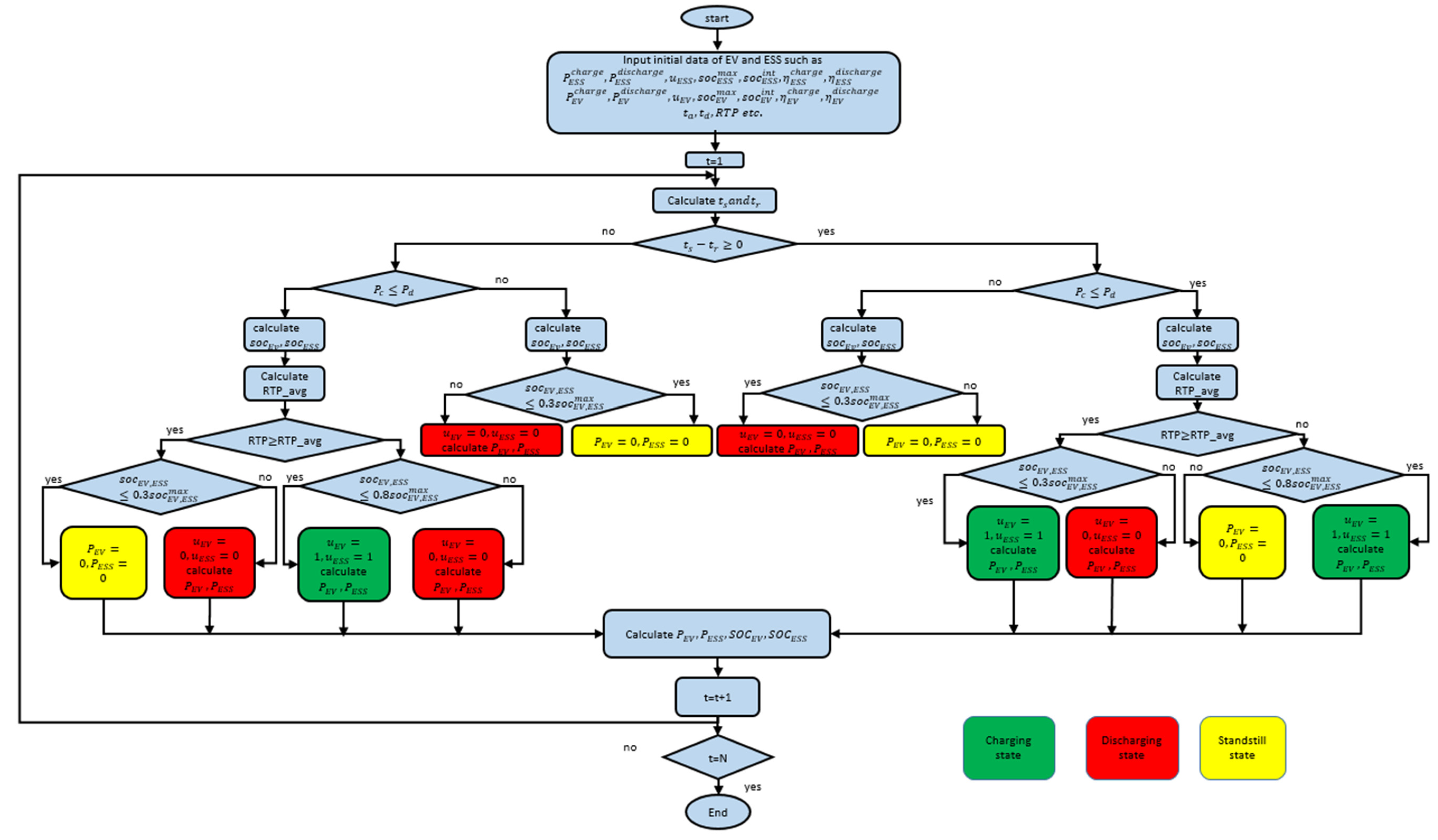
This section presents a novel charging and discharging scheme of ESS and EV in the HEMS paradigm. This scheme provides more economic benefits, reduces stress on the main grid, increases bettery performance, and fulfills the user’s travel demand. The scheme considers the maximum power demand limit of the home, the availability of EV, and RTP provided by the utility firm, besides technical constraints of ESS and EV. The charging and discharging of ESS and EV have been done according to the parameters mentioned above. Let t s be the total time span of EV available at home, and t r is the total time required by the EV to reach 0.8 S O C m a x from an initial state. The t s   a n d   t r have been calculated using the following equations:
t s = t d t a
S O C E V ( t ) = S O C E V i n i t i a l + P E V c h a r g e ( t ) × u E V ( t ) × t r × η E V c h a r g e + P E V d c h a r g e ( t ) × ( 1 u E V ( t ) ) × t r / η E V d c h a r g e
The decision of the charging and discharging scheme is shown in Figure 2.

5. Optimization Module

PSO is a metaheuristic optimization algorithm that is inspired from a flock of birds. The bird (particle) moves around the search space for the best solution. Each particle in PSO should consider the current position, current velocity, the distance to their best solution (Pbest), and the distance to their global best solution (Gbest) to modify its position. PSO was mathematically modeled as follows:
V i t + 1 = W V i t + C 1 × r a n d × ( P b e s t i x i t ) + C 2 × r a n d × ( g b e s t x i t )
x i t + 1 = x i t + V i t + 1
where V i t is the velocity of i t h particle at iteration t, W is the weighting coefficient, C1 is an acceleration coefficient, and rand is the random number between 0 and 1. x i t is the current position of the i t h   particle at iteration t, Pbest is the best solution that the i t h particle has obtained so far, and gbest indicates the best solution that the swarm has obtained so far.
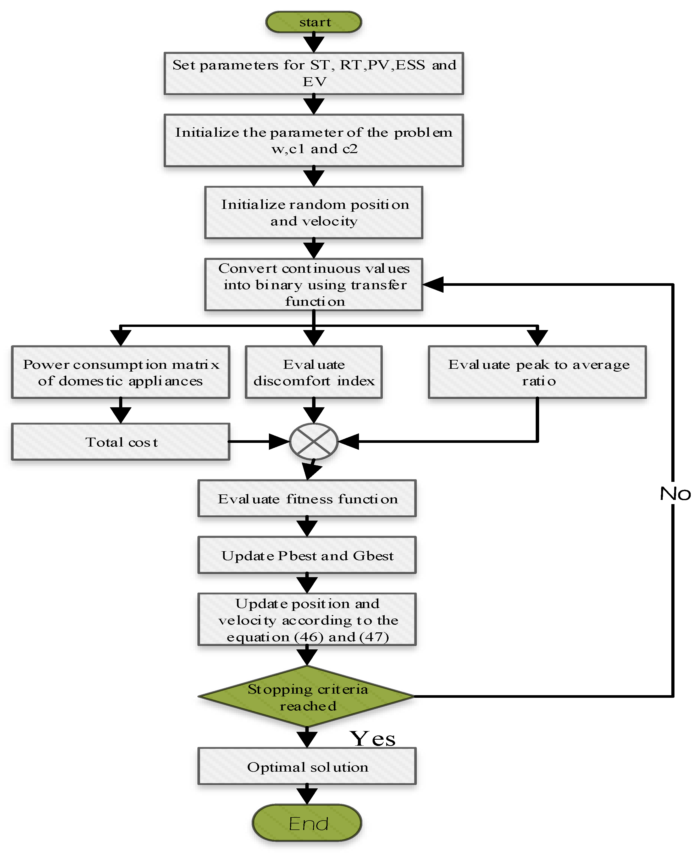
The PSO starts with randomly placing the particle in the problem space. At each iteration, the velocities of the particles are calculated using Equation (46). After calculating the velocities, the position of particles can be calculated using Equation (47). The process of changing the position of the particle will continue until it satisfies the end criteria.
The HEMS optimization has a binary search space. The status of the appliance is either 0 (OFF) or 1 (ON). In binary search space, the position updating means switching between “0” and “1” values. The switching should be done in the velocities. To change the continuous space to binary space, the position of an agent is mapped with the propability of its velocity. A sigmoid function, as in Equation (48), was employed to transform all the real values of velocities to probability values in the interval [0,1]:
T ( V i k ( t ) ) = 1 1 + e V i k ( t )
where V i k ( t ) indicates the velocities of particle i at iteration t in the i t h dimension.
After converting velocities to probability values, the position could be updated with the probability of their velocities as follows:
x i t ( t + 1 ) = { 0 i f   r a n d T ( V i k ( t + 1 ) 1 i f   r a n d T ( V i k ( t + 1 )
The general steps of the Binary PSO (BPSO) algorithm are as follows:
  • All particles have initialized with random values.
  • For all particles, velocities are defined using Equation (46).
  • Calculate probabilities for changing the elements of position vector using Equation (48).
  • Update the elements of position vectors with Equation (49)
  • Calculate the objective function “O”.
  • Repeat until satisfying the end condition.
This strategy is used to address a single objective problem. We use the weighted sum technique proposed in [5,10] to solve multi-objective problems. Energy costs, PAR, and DI are all being optimized simultaneously. The MOF is defined in Equation (43), which is now defined as follows:
O = M O F
By changing the value of w 1 , w 2 , and   w 3 we find the best trade-off between different objectives.
The Flowchart of BPSO, with respect to our proposed algorithm, is shown in Figure 3.

6. Result and Discussion

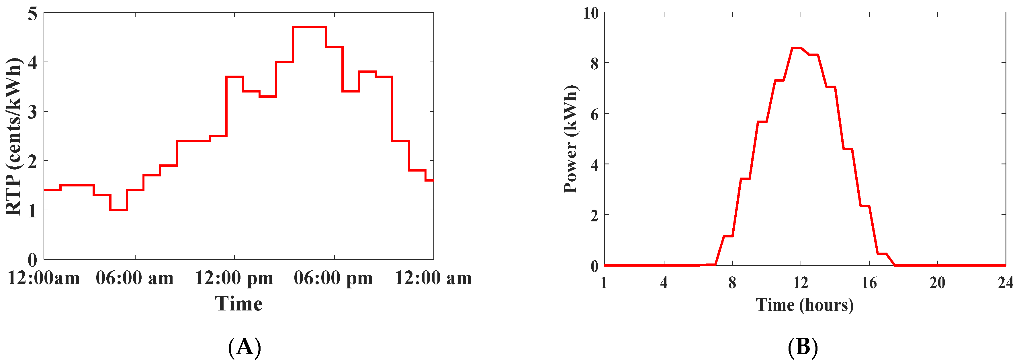
In this paper, we took real-time appliances, shiftable appliances, PV, EV, and ESS. The power consumption, the number of hours required to complete its operation, and the base operating time are given in Table 2. The RTP data was obtained from [5], while the PV data was obtained from [50]. Both the datasets have been shown in Figure 4A,B, respectively. The EV and ESS data were obtained from [9] and given in Table 3. The HEMS worked on both G2H and H2G modes. When the power was deficient, HEMS imported power from the grid, and when there was surplus energy, HEMS returned energy to the grid. The power selling rate was 0.75 of utility RTP. The EV was not available in home between 8 to 22 h. The ESS was always available at home, and its charging and discharging scheme are shown in Figure 2. The simulation results were carried out on intel core-i5 with 4GB RAM. MATLAB 2016b was used to carry out the proposed scheme.

6.1. Case 1: Single Objective Optimization

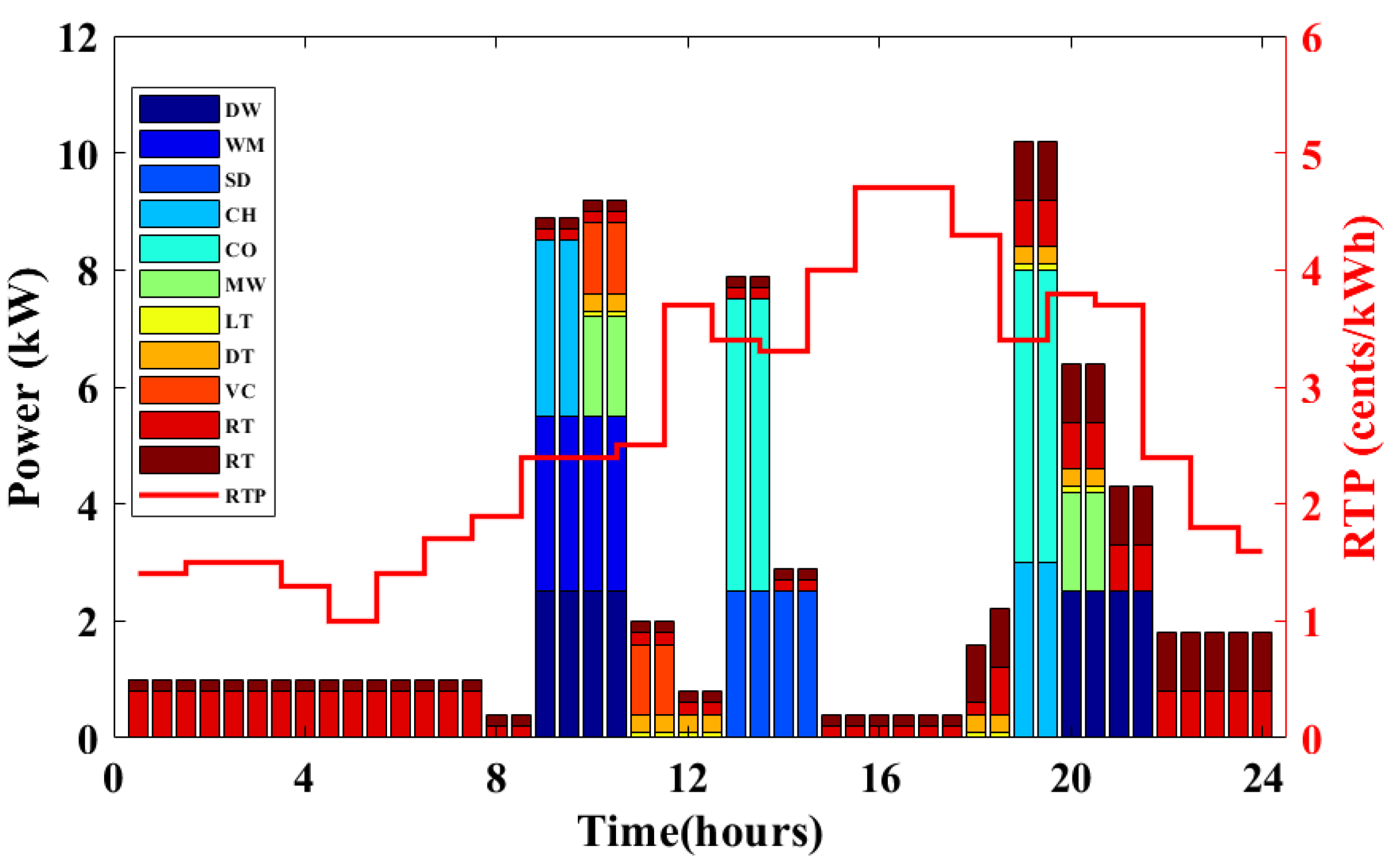
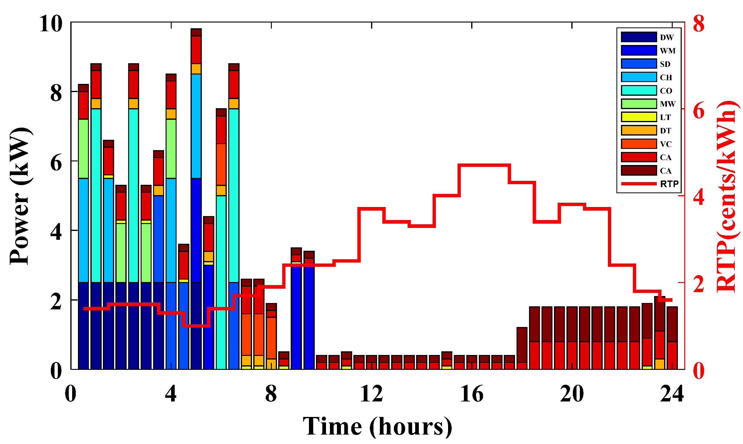
The simulation results are depicted in Figure 5, Figure 6, Figure 7, Figure 8, Figure 9 and Figure 10. Figure 5 depicts the basic appliance schedule. All of the appliances were set to operate at their preferred timeslot. For example, the cooking oven was on at 13, 13:30, 19, and 19:30. Figure 6 depicts the scheduling of household appliances using the BPSO optimization algorithm. The goal was to reduce the total operating cost of household appliances. Figure 6 clearly shows that the majority of the appliances were running in low RTP time periods. The maximum power requirement was set at 10 kW, ensuring that power usage in each time slot never surpassed this limit. Real-time appliances were not scheduled since they must be utilized in real-time. The RT appliances or critical appliances were running during their baseline time slot. The BPSO minimized the operating cost, considering the constraints given in Equation (6). For example, if the washing machine should run for two hours to optimize electricity use, BPSO would run it for two hours exactly. Similarly, the spine dryer should run for two hours, which is precisely what the BPSO would do, and so on.
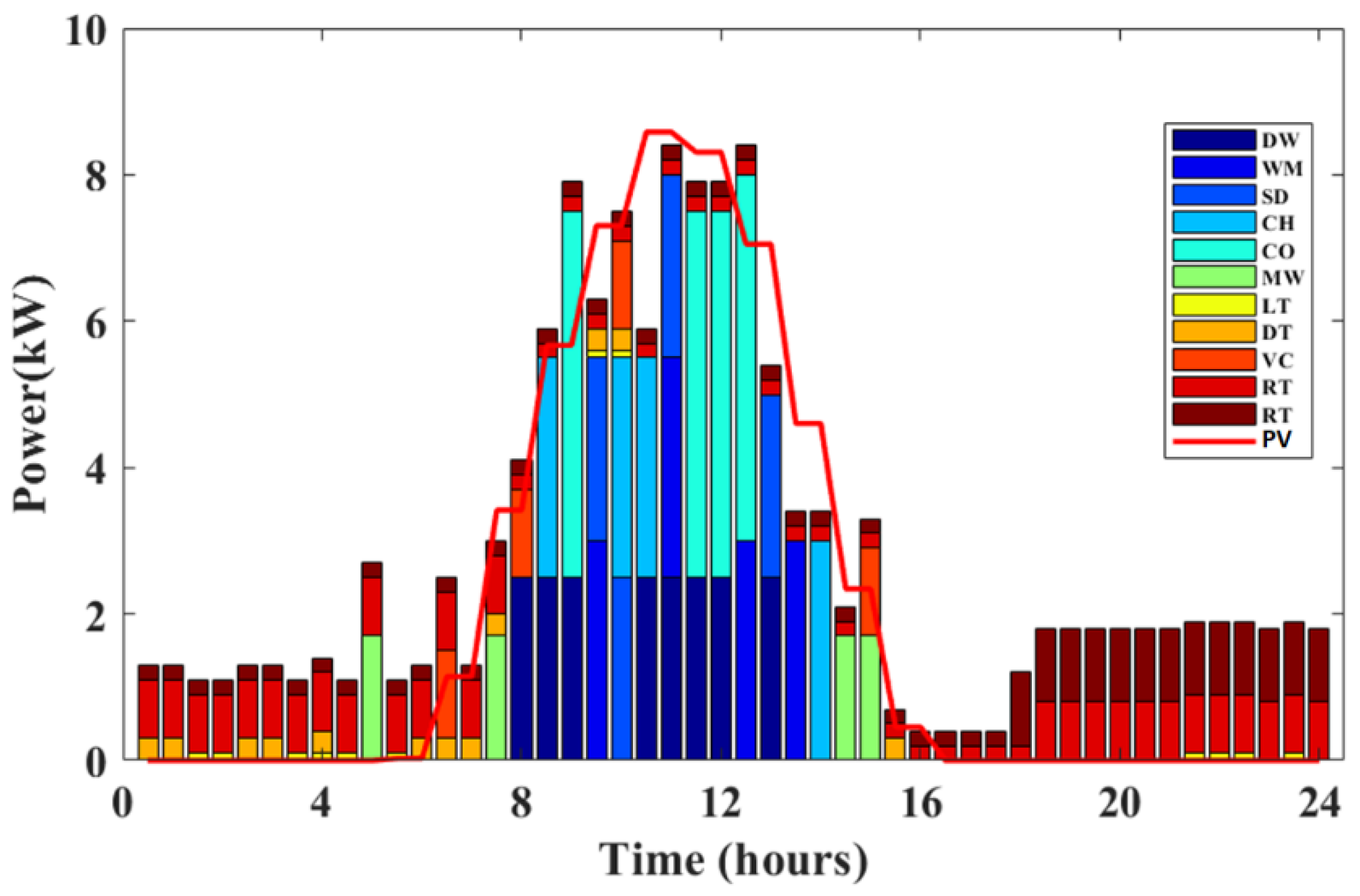
Figure 7 depicts appliance scheduling when PV is integrated into the home. PV electricity should have been efficiently utilized to reduce operational costs. As seen in Figure 7, the proposed scheme operated the majority of the appliances when PV power is available. PV excess electricity was sold back to the grid for further economic advantages. The suggested HEMS optimization technique maximized PV power usage.
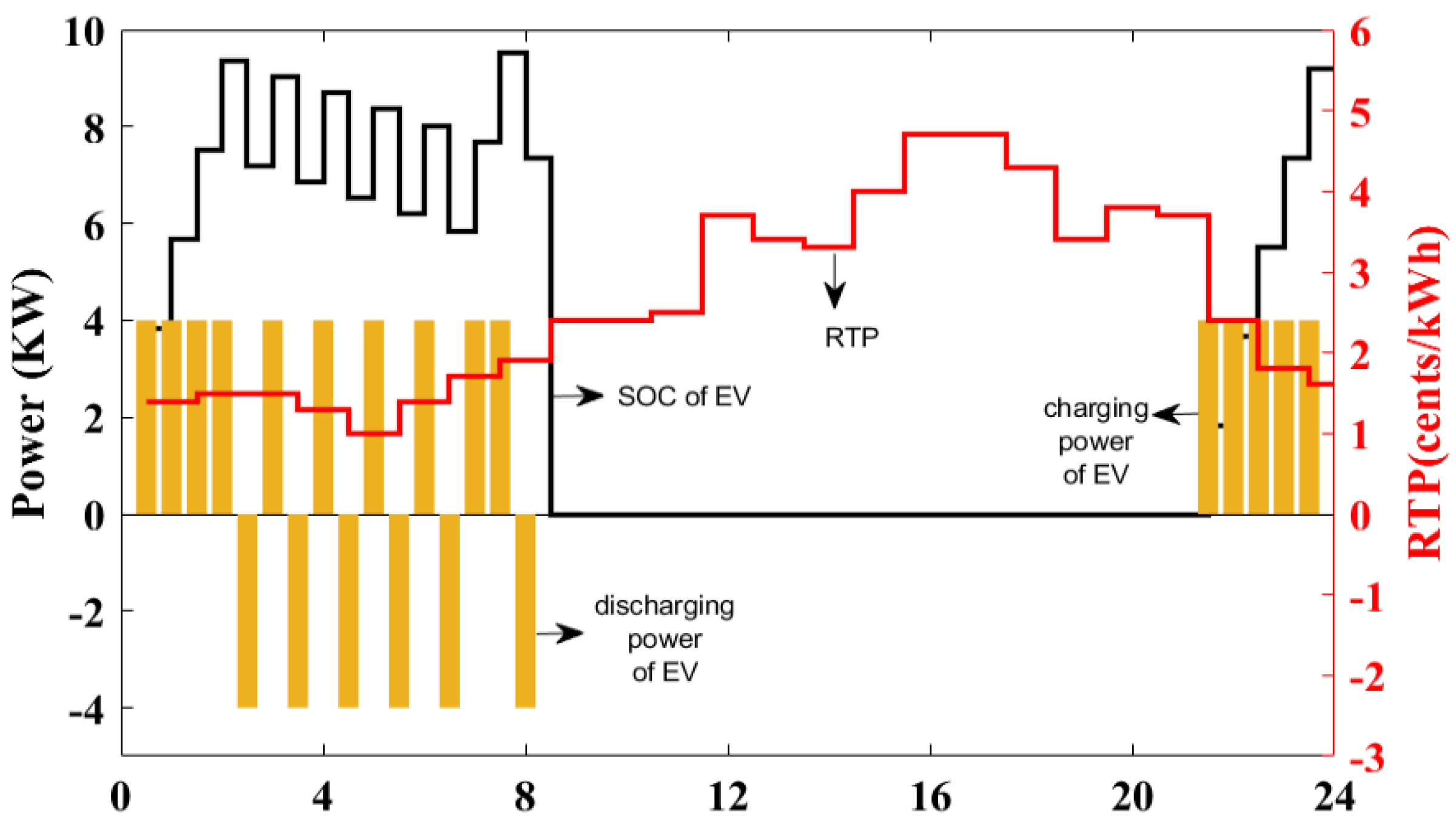
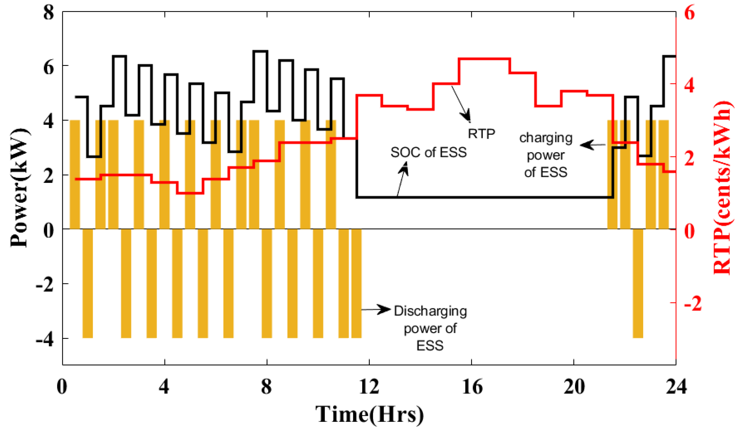
Figure 8 depicts the charging and discharging of an EV. The charging and discharging took place in accordance with the charging/discharging strategy described in Section 3. The charging and discharging considered RTP, current SOC, maximum SOC, power demand limit, and availability of EV. The EV was charged at specific times, such as 0:30, 1:00, 1:30, and 2:00. The EV was discharged during any instance such as 2:30, 3:30, 4:30, 5:30, and so on. Because the EV was unavailable at home between 9 and 21, its SOC and power consumption were zero. Domestic appliances made use of the discharge power. The HEMS algorithm could transmit it back to the grid and earn revenue if there was excess power. Figure 8 depicts the fluctuation of SOC, power charge/discharge, and RTP. Because ESS was always available at home, it was charged and discharged in accordance with the charging and discharging system given in Section 3. Figure 9 depicts the SOC, power (charge/discharge), and RTP. The ESS was charged at a variety of times, including 0:30, 1:30, 2:00, and 3:00. The ESS discharged at various times such as 1:00, 2:30, 3:30, and so on. The ESS was in standstill mode and maintained a minimum charge level, while the RTP was high between 12:00 and 21:30. The ESS maintained a minimal SOC to optimize battery efficiency and durability. The charging power was provided by PV or MG. The discharge power was utilized to power the household appliances while the excess charge was returned to the MG.
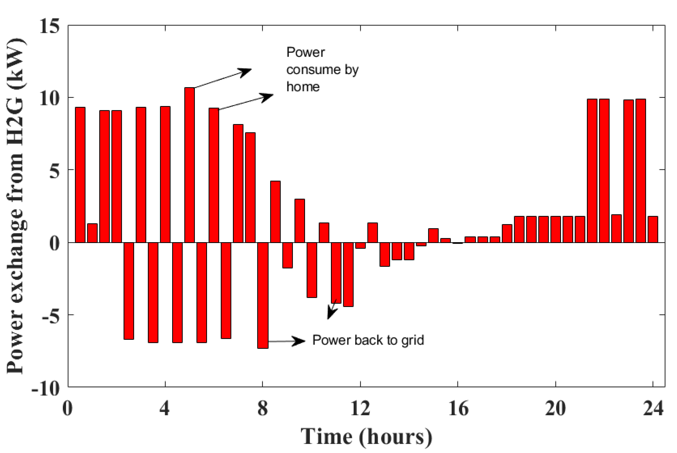
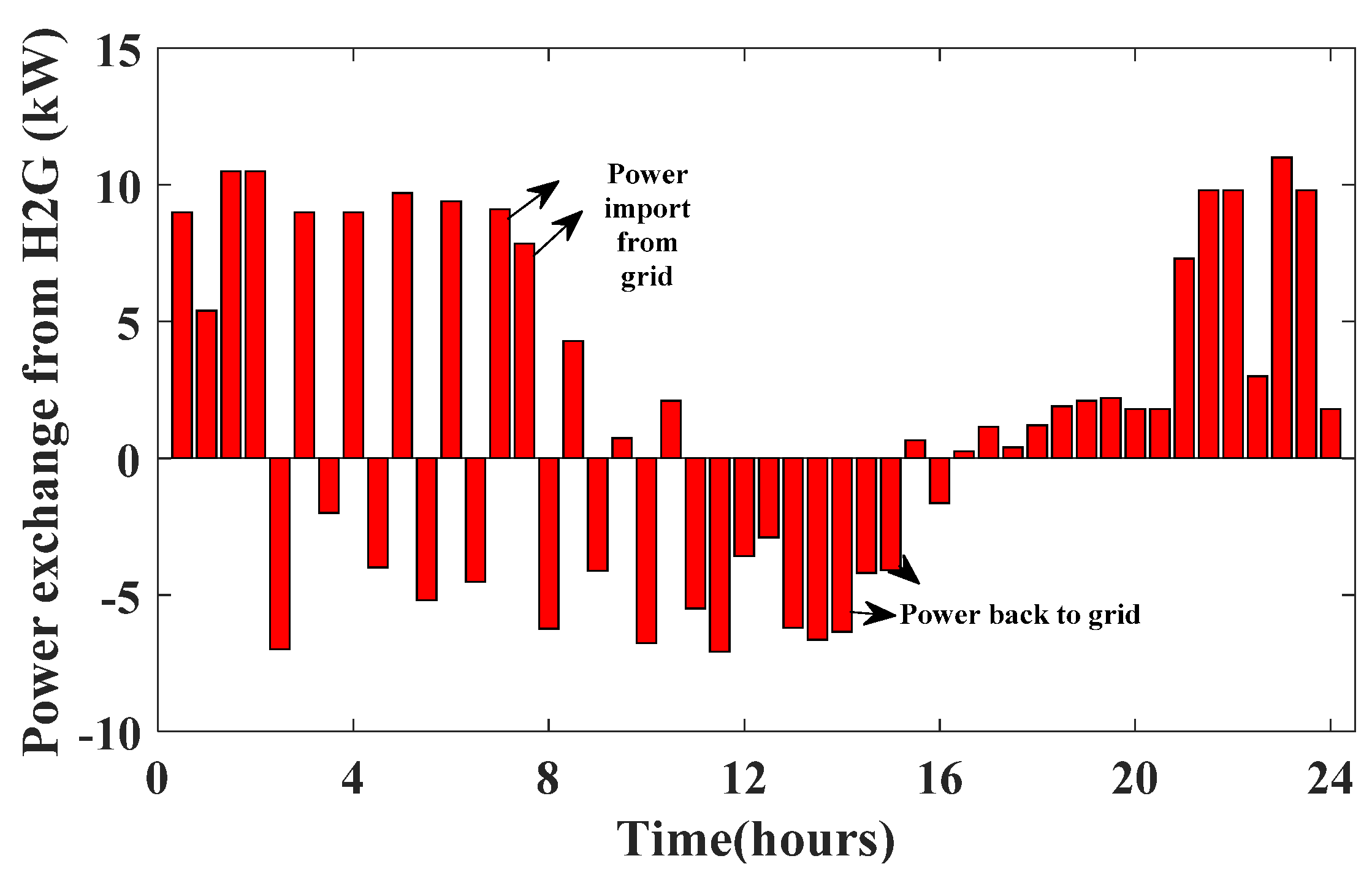
Figure 10 depicts the interaction of the MG with the integrated home appliances, PV, EV, and ESS. Because PV electricity was available, the power drawn from the main grid between 9:00 and 17:00 was kept to a bare minimum. The suggested method was capable of utilizing all of the PV electricity. The power consumption from the grid was mainly in the early hour or last hours because RTP was low in these time slots. The positive power represents electricity imported from the grid, while the negative power represents power provided to the grid. Because the ESS and EV were fully charged in the early hours, they discharged their electricity to the grid at this time. HEMS used the least amount of energy during high RTP periods.
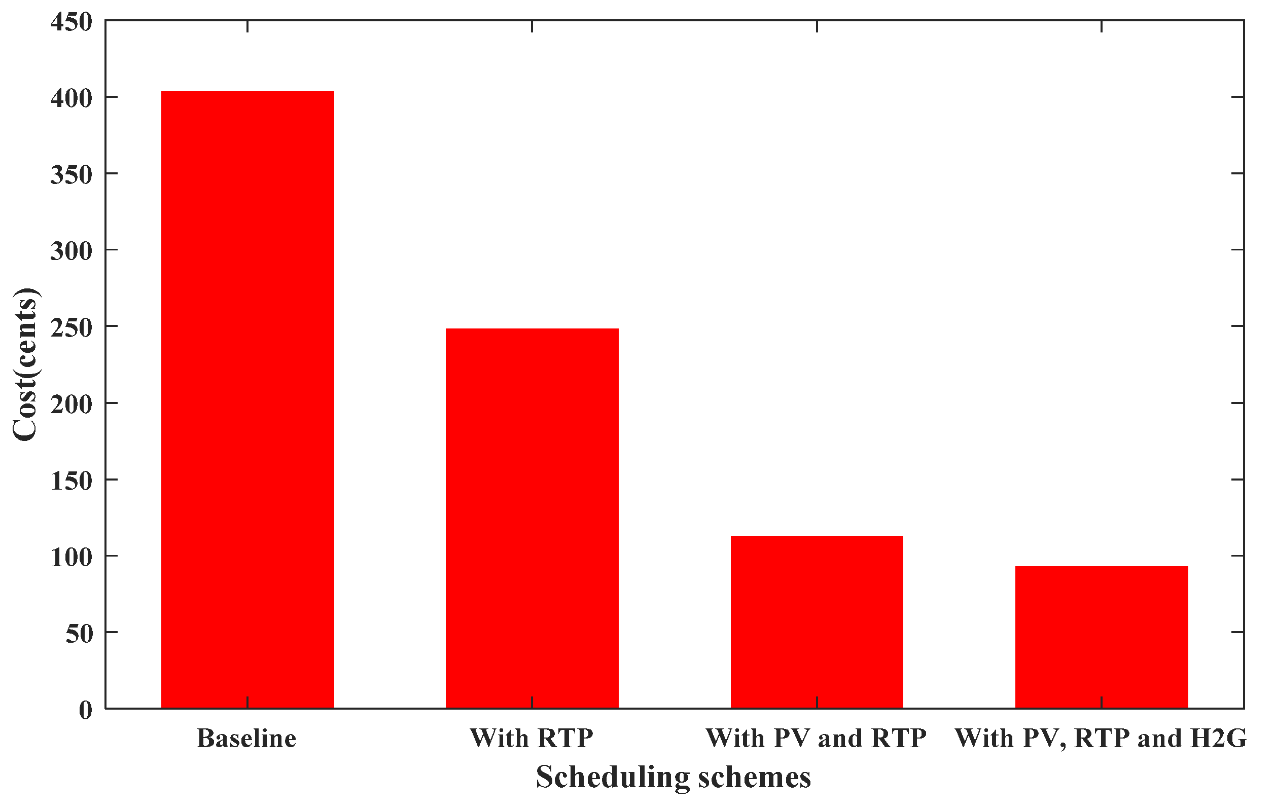
The running cost of home appliances without scheduling was 402.89 cents. When the optimization system scheduled the home appliances using RTP, the cost was decreased to 248.1 cents, or 38.42%. The addition of PV reduced the cost to 170.55 cents, a savings of 57.66%. The ESS and EV charges were at minimum prices and delivered power to the domestic appliances in high RTP hours or back surplus energy to the grid. This occurrence cut the price even further to 112.15 cents. The operating cost of domestic appliances with different scheduling schemes considered is shown in Figure 11.

6.2. Case 2: Multi-Objective Optimazation

In the previous section, we discussed cost minimization as a single objective problem. When the optimization algorithm minimized the cost, it affected the system PAR and the user’s satisfaction. Therefore, in this section, we formulated a multi-objective problem PAR of the system, customer dissatisfaction, along with cost minimization. The multi-objective problem is formulated in Equation (43). By changing the value of weighting coefficients, we could find the best possible solution. These objectives are conflicting in nature. When we tried to minimize the one objective that would significantly affect the other two objectives. Therefore, we had to find the best trade-off between these objectives. The authors have considered three cases, which are described in Table 4.
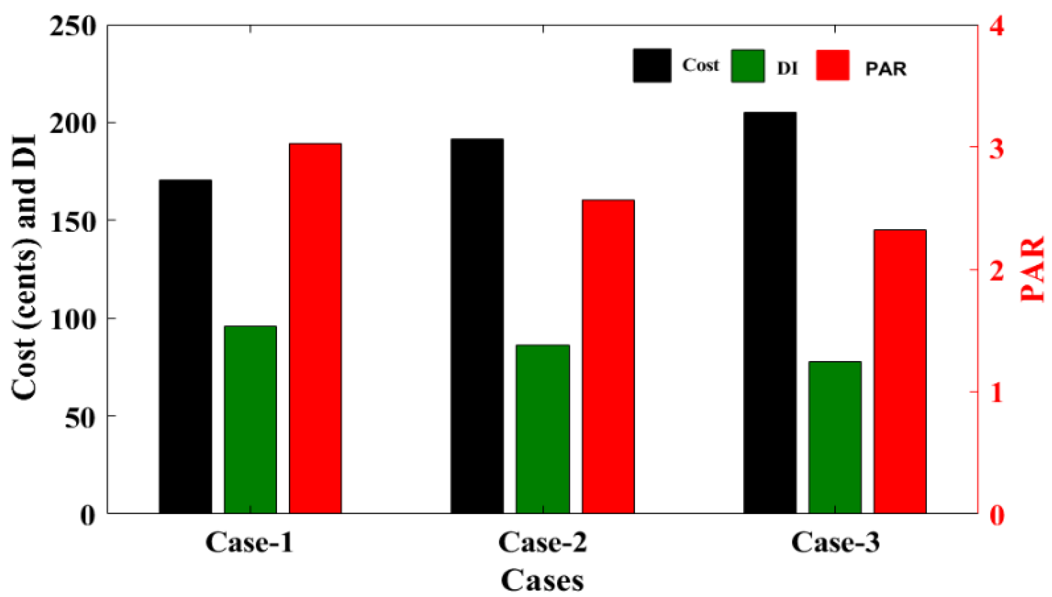
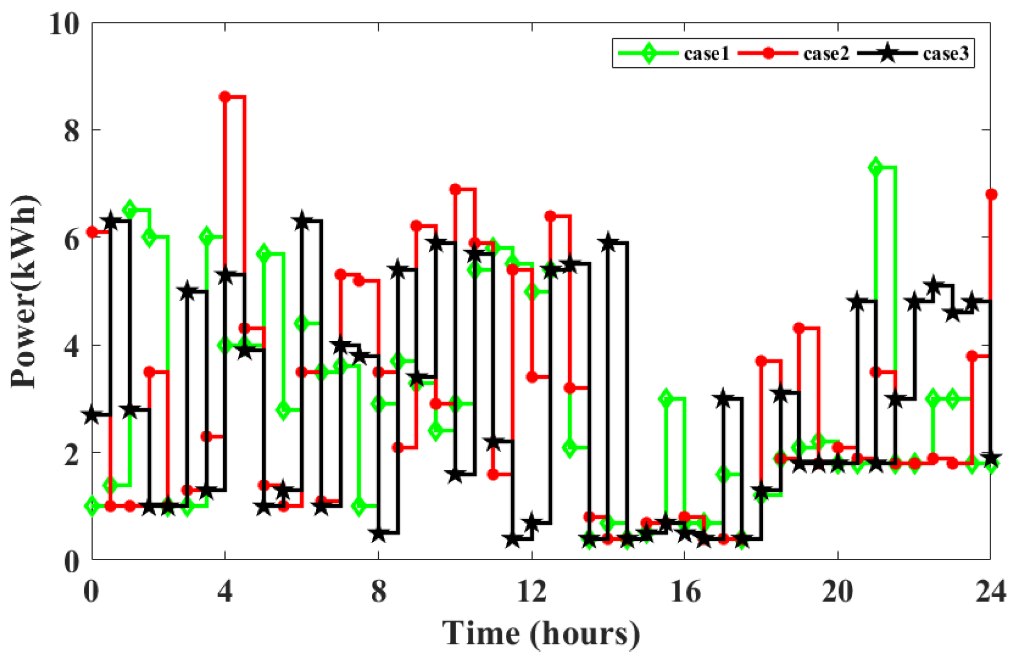
The energy cost, PAR, and DI obtained from different cases are shown in Figure 12. In case-1 (w1 = 1, w2 = 0, and w3 = 0) the cost was only minimized by putting w2 = w3 = 0. The cost, PAR, and DI obtained were 170.51 cents, 3.0308, and 96, respectively. From the Figure 12, it is clear that the PAR and DI were very high when only cost was minimized. To reduce the PAR and DI, the weighting coefficient w2 and w3 should increase. In case-2 (w1 = 1, w2 = 20 and w3 = 5), the PAR reduced to 2.5727 and a decrease of 15.11% was achieved, while DI reduced to 80 and a decrease of 16.67% was achieved. To further reduce the PAR and DI, the weight of w2 and w3 further increased. In case-3, w1 = 1, w2 = 40 and w3 = 20. The increased weight of w2 and w3 reduced the PAR and DI to 23.25% and 29.17%, respectively, from case-1. By reducing PAR and DI, the electricity price slightly increased and an increment of 20.39% was observed. The comparison bar graph for all three cases is shown in Figure 12. The power scheduling of all three cases during the 24 h is shown in Figure 13.
From the above discussion of the multi-objective problem, case-2 was found to be optimal. Figure 14 depicts the power transferred in case-2 when combined with H2G capabilities. When solar panels provided electricity to the house, the energy was used by the appliances, and any leftovers were sent back into the grid. The grid imported power mostly in the early hours of the day in order to strike a balance between several goals. The overall cost of energy was lowered by 29.41% with H2G integration, and it was then just 120.48 cents per day.

7. Conclusions

This study proposed a novel HEMS with the integration of PV, EV, and ESS. The objective was to minimize the electricity cost, system PAR, and user’s discomfort. The BPSO was utilized as an optimization tool to obtain the best results. For single-objective optimization, the HEMS only minimized the cost, and BPSO scheduled most of the appliances in a low price period. This strategy hampered the system PAR and DI. Therefore, a multi-objective problem was formulated, which minimized PAR and DI, along with cost. The proposed scheme reduced the cost by 52.47% from base schedule price, while the PAR and DI were reduced by 15.11% and 16.67%, respectively. Moreover, the proposed charging/discharging scheme of EV/ESS minimized the cost, fed back power to the grid at peak periods, increased battery life, and satisfied users’ traveling needs. It also has H2G capability, therefore the surplus power obtained from PV and discharging of EV/ESS was fed back to the grid. The selling of electricity to MG further reduced the electricity cost by 29.41%.
The proposed HEMS not only minimized the cost, PAR, and DI, but it also lowered the power import from the grid and supplied power during peak periods. This increased the grid efficiency and reliability under uncertain imbalance conditions.

Author Contributions

Conceptualization, A.M.; formal analysis, A.M.; funding acquisition, M.A. (Marwan Alsultan), S.A.; investigation, A.M., M.Z. and I.A.; resources, M.A. (Mali Abdollahian); methodology, A.M.; project administration, I.A., A.S., M.A. (Marwan Alsultan) and S.A.; visualization, M.A. (Mali Abdollahian); supervision, I.A.; writing–original draft, A.M.; writing–review and editing, M.Z., I.A. All authors have read and agreed to the published version of the manuscript.

Funding

The authors extend their appreciation to King Saud University for funding this work through Researchers Supporting Project number (RSP-2021/313), King Saud University, Riyadh, Saudi Arabia.

Institutional Review Board Statement

Not Applicable.

Informed Consent Statement

Not Applicable.

Data Availability Statement

Not Applicable.

Acknowledgments

The authors extend their appreciation to King Saud University for funding this work through Researchers Supporting Project number (RSP-2021/313), King Saud University, Riyadh, Saudi Arabia.

Conflicts of Interest

The authors declare no conflict of interest.

Nomenclature and Abbreviations

Nomenclature
HEMSHome Energy Management System
HPEMCHeuristic-Based Programmable Energy Management Controller
RESRenewable Energy Resources
WTWind Turbines
DGDistributed Generation
HPHeat Pump
PVPhotovoltaic
ESSEnergy Storage System
EVElectric Vehicle
SMSmart Meter
MCMain Controller
MGMain Grid
PSOParticle Swarm Optimization
BPSOBinary Particle Swarm Optimization
ELPSOEnhance Leader Particle Swarm Optimization
MILPMixed-Integer Linear Programming
GAGenetic Algorithm
MINLPMixed-Integer Nonlinear Programming
GWOGrey Wolf Optimizer
DPDynamic Programming
RBARule-Based Algorithm
HGPOHybrid Genetic Particle Swarm Optimization
ACOAnt Colony Optimization
WDOWind-Driven Optimization
BOAButterfly Optimization Algorithm
V2HVehicle To Home
V2GVehicle To Grid
H2GHome To Grid
G2HGrid To Home
DSMDemand Side Management
DRDemand Response
RTPReal Time Pricing
TOUTime of Use
PARPeak to Average Ratio
DIDiscomfort Index
EMCEnergy Management Controller
IBRInclination Block Rate
BFABacterial Foraging Algorithm
DFADragonfly Algorithm
AHPAnalytical Hierarchy Process
LPLinear Programming
MEHMultiple Energy Hubs
MHSModified Harmony Search
DEMSDistrict Energy Management System
MIQPMixed-Integer Quadratic Programming
GSAGravitational Search Algorithm
CSOCuckoo Search Optimization
RTReal-Time Appliance
STShiftable Appliance
MOFMulti-Objective Function
Abbreviations
R i , n Status of i t h real-time appliance in n t h time slot.
P i , n R T The power consumption of i t h RT appliances in n t h slot
E i , n R T The energy consumption of i t h RT appliances in n t h slot
Δ t Time interval
E t o t a l R T The total energy consumed in a day by RT appliance
S j The starting time of j t h appliance
x k , n The status of k t h shiftable appliances in n t h time slot
l b j Lower bound starting time for j t h shiftable appliance
u b j Upper bound starting time for j t h shiftable appliance
N j The number of time slots are required to complete the operation of each ST appliance
P k , n S T The power consumption of i t h ST appliances in n t h slot
E k , n S T The energy consumption of i t h ST appliances in n t h slot
E t o t a l S T The total energy consumed in a day by ST appliance
P P V The output power of PV
S I Solar horizontal irradiation
η P V Solar conversion efficiency of the installed PV system
E P V     The energy generated by PV in time interval Δ t
E P V l o a d The PV energy utilized by the appliance load
E P V E V c h a r g e The PV energy used for EV charging
E P V E S S c h a r g e The PV energy used for ESS charging
E t o t a l The total energy consumption of home in a day
E H 2 G The surplus energy transferred back to the MG
μ The energy transfer variable status from G2H or H2G
P E S S The power supplied/consumed by ESS
P E S S c h a r g e The charging power of ESS
P E S S d c h a r g e The discharging power of ESS
u E S S The status of ESS
E t o t a l E S S The total energy consumed/delivered in a day by ESS
S O C E S S State of charge of EV
η E S S c h a r g e Charging efficiency of ESS
η E S S d c h a r g e Discharging efficiency of ESS
S O C E S S i n t Intial state of charge of ESS
P E S S c h m a x Maximum charging power of ESS
P E S S d c h a r m a x Maximum discharging power of ESS
P E V The power supplied/consumed by EV
P E V c h a r g e The charging power of EV
P E V d c h a r g e The discharging power of EV
u E V The status of EV
E t o t a l E V The total energy consumed/delivered in a day by EV
S O C E V State of charge of EV
η E V c h a r g e Charging efficiency of EV
η E V d c h a r g e Discharging efficiency of EV
S O C E V i n t Intial state of charge of EV
P E V c h m a x Maximum charging power of EV
P E V d c h a r m a x Maximum discharging power of EV

References

  1. Nguyen, H.T.; Nguyen, D.T.; Le, L.B. Energy management for households with solar assisted thermal load considering renewable energy and price uncertainty. IEEE Trans. Smart Grid 2015, 6, 301–314. [Google Scholar] [CrossRef]
  2. Rottondi, C.; Barbato, A.; Chen, L.; Verticale, G. Enabling privacy in a distributed game-theoretical scheduling system for domestic appliances. IEEE Trans. Smart Grid 2017, 8, 1220–1230. [Google Scholar] [CrossRef]
  3. Molla, T.; Khan, B.; Moges, B.; Alhelou, H.H.; Zamani, R.; Siano, P. Integrated energy optimization of smart home appliances with cost-effective energy management system. CSEE J. Power Energy Syst. 2019, 5, 249–258. [Google Scholar] [CrossRef]
  4. Celik, B.; Roche, R.; Bouquain, D.; Miraoui, A. Decentralized neighborhood energy management with coordinated smart home energy sharing. IEEE Trans. Smart Grid 2018, 9, 6387–6397. [Google Scholar] [CrossRef] [Green Version]
  5. Rezaee Jordehi, A. Enhanced leader particle swarm optimisation (ELPSO): A new algorithm for optimal scheduling of home appliances in demand response programs. Artif. Intell. Rev. 2020, 53, 2043–2073. [Google Scholar] [CrossRef]
  6. Althaher, S.; Member, S.; Mancarella, P.; Member, S. Management System Under Dynamic Pricing. IEEE Trans. Smart Grid 2015, 6, 1874–1883. [Google Scholar] [CrossRef]
  7. Zhao, Z.; Lee, W.C.; Shin, Y.; Song, K. Bin An optimal power scheduling method for demand response in home energy management system. IEEE Trans. Smart Grid 2013, 4, 1391–1400. [Google Scholar] [CrossRef]
  8. Dinh, H.T.; Yun, J.; Kim, D.M.; Lee, K.H.; Kim, D. A Home Energy Management System with Renewable Energy and Energy Storage Utilizing Main Grid and Electricity Selling. IEEE Access 2020, 8, 49436–49450. [Google Scholar] [CrossRef]
  9. Abdelaal, G.; Gilany, M.I.; Elshahed, M.; Sharaf, H.M.; El’Gharably, A. Integration of Electric Vehicles in Home Energy Management Considering Urgent Charging and Battery Degradation. IEEE Access 2021, 9, 47713–47730. [Google Scholar] [CrossRef]
  10. Oprea, S.V.; Bâra, A.; Ifrim, G. Flattening the electricity consumption peak and reducing the electricity payment for residential consumers in the context of smart grid by means of shifting optimization algorithm. Comput. Ind. Eng. 2018, 122, 125–139. [Google Scholar] [CrossRef]
  11. Dinh, H.T.; Kim, D. An Optimal Energy-Saving Home Energy Management Supporting User Comfort and Electricity Selling with Different Prices. IEEE Access 2021, 9, 9235–9249. [Google Scholar] [CrossRef]
  12. Sarker, E.; Seyedmahmoudian, M.; Jamei, E.; Horan, B.; Stojcevski, A. Optimal management of home loads with renewable energy integration and demand response strategy. Energy 2020, 210, 118602. [Google Scholar] [CrossRef]
  13. Kaluthanthrige, R.; Rajapakse, A.D. Demand response integrated day-ahead energy management strategy for remote off-grid hybrid renewable energy systems. Int. J. Electr. Power Energy Syst. 2021, 129, 106731. [Google Scholar] [CrossRef]
  14. Oprea, S.V.; Bâra, A.; Preda, Ș.; Tor, O.B. A Smart Adaptive Switching Module Architecture Using Fuzzy Logic for an Efficient Integration of Renewable Energy Sources. A Case Study of a RES System Located in Hulubești, Romania. Sustainability 2020, 12, 6084. [Google Scholar] [CrossRef]
  15. Sangswang, A.; Konghirun, M. Optimal Strategies in Home Energy Management System Integrating Solar Power, Energy Storage, and Vehicle-to-Grid for Grid Support and Energy Efficiency. IEEE Trans. Ind. Appl. 2020, 56, 5716–5728. [Google Scholar] [CrossRef]
  16. Imran, A.; Hafeez, G.; Khan, I.; Member, S.; Qazi, A.B.; Khalid, A.; Thoben, K. Heuristic-Based Programable Controller for Efficient Energy Management Under Renewable Energy Sources and Energy Storage System in Smart Grid. IEEE Access 2020, 8, 139587–139608. [Google Scholar] [CrossRef]
  17. Ben Slama, S. Design and implementation of home energy management system using vehicle to home (H2V) approach. J. Clean. Prod. 2021, 312, 127792. [Google Scholar] [CrossRef]
  18. Alilou, M.; Tousi, B.; Shayeghi, H. Home energy management in a residential smart micro grid under stochastic penetration of solar panels and electric vehicles. Sol. Energy 2020, 212, 6–18. [Google Scholar] [CrossRef]
  19. Aznavi, S.; Fajri, P.; Asrari, A.; Harirchi, F. Realistic and Intelligent Management of Connected Storage Devices in Future Smart Homes Considering Energy Price Tag. IEEE Trans. Ind. Appl. 2020, 56, 1679–1689. [Google Scholar] [CrossRef]
  20. Yousefi, M.; Hajizadeh, A.; Soltani, M.N.; Hredzak, B. Predictive Home Energy Management System with Photovoltaic Array, Heat Pump, and Plug-In Electric Vehicle. IEEE Trans. Ind. Inform. 2021, 17, 430–440. [Google Scholar] [CrossRef]
  21. ur Rehman, U.; Yaqoob, K.; Adil Khan, M. Optimal power management framework for smart homes using electric vehicles and energy storage. Int. J. Electr. Power Energy Syst. 2022, 134, 107358. [Google Scholar] [CrossRef]
  22. van der Kam, M.; van Sark, W. Smart charging of electric vehicles with photovoltaic power and vehicle-to-grid technology in a microgrid; a case study. Appl. Energy 2015, 152, 20–30. [Google Scholar] [CrossRef] [Green Version]
  23. Poursmaeil, B.; Hosseinpour Najmi, P.; Najafi Ravadanegh, S. Interconnected-energy hubs robust energy management and scheduling in the presence of electric vehicles considering uncertainties. J. Clean. Prod. 2021, 316, 128167. [Google Scholar] [CrossRef]
  24. Rabiee, A.; Sadeghi, M.; Aghaeic, J.; Heidari, A. Optimal operation of microgrids through simultaneous scheduling of electrical vehicles and responsive loads considering wind and PV units uncertainties. Renew. Sustain. Energy Rev. 2016, 57, 721–739. [Google Scholar] [CrossRef]
  25. Zeynali, S.; Rostami, N.; Ahmadian, A.; Elkamel, A. Stochastic energy management of an electricity retailer with a novel plug-in electric vehicle-based demand response program and energy storage system: A linearized battery degradation cost model. Sustain. Cities Soc. 2021, 74, 103154. [Google Scholar] [CrossRef]
  26. AL-Dhaifallah, M.; Ali, Z.M.; Alanazi, M.; Dadfar, S.; Fazaeli, M.H. An efficient short-term energy management system for a microgrid with renewable power generation and electric vehicles. Neural Comput. Appl. 2021, 33, 16095–16111. [Google Scholar] [CrossRef]
  27. Torres-Moreno, J.; Gimenez-Fernandez, A.; Perez-Garcia, M.; Rodriguez, F. Energy Management Strategy for Micro-Grids with PV-Battery Systems and Electric Vehicles. Energies 2018, 11, 522. [Google Scholar] [CrossRef] [Green Version]
  28. Wang, D.; Guan, X.; Wu, J.; Li, P.; Zan, P.; Xu, H. Integrated Energy Exchange Scheduling for Multimicrogrid System with Electric Vehicles. IEEE Trans. Smart Grid 2016, 7, 1762–1774. [Google Scholar] [CrossRef] [Green Version]
  29. Fanti, M.P.; Mangini, A.M.; Roccotelli, M.; Ukovich, W. District Microgrid Management Integrated with Renewable Energy Sources, Energy Storage Systems and Electric Vehicles *. * This work is supported by the project Smart Cities and Communities and Social Innovation Pilot 2014–2016-ASMARA. IFAC-PapersOnLine 2017, 50, 10015–10020. [Google Scholar] [CrossRef]
  30. Raya-Armenta, J.M.; Bazmohammadi, N.; Avina-Cervantes, J.G.; Sáez, D.; Vasquez, J.C.; Guerrero, J.M. Energy management system optimization in islanded microgrids: An overview and future trends. Renew. Sustain. Energy Rev. 2021, 149, 111327. [Google Scholar] [CrossRef]
  31. Lee, J.Y.; Choi, S.G. Linear programming based hourly peak load shaving method at home area. In Proceedings of the 16th International Conference on Advanced Communication Technology; Global IT Research Institute (GIRI), Pyeongchang, Korea, 16–19 February 2014; pp. 310–313. [Google Scholar]
  32. Emami Javanmard, M.; Ghaderi, S.F.; Sangari, M.S. Integrating energy and water optimization in buildings using multi-objective mixed-integer linear programming. Sustain. Cities Soc. 2020, 62, 102409. [Google Scholar] [CrossRef]
  33. Ogunjuyigbe, A.S.O.; Ayodele, T.R.; Oladimeji, O.E. Management of loads in residential buildings installed with PV system under intermittent solar irradiation using mixed integer linear programming. Energy Build. 2016, 130, 253–271. [Google Scholar] [CrossRef]
  34. Wittmann, F.M.; Lopez, J.C.; Rider, M.J. Nonintrusive Load Monitoring Algorithm Using Mixed-Integer Linear Programming. IEEE Trans. Consum. Electron. 2018, 64, 180–187. [Google Scholar] [CrossRef]
  35. Huang, Y.; Wang, W.; Hou, B. A hybrid algorithm for mixed integer nonlinear programming in residential energy management. J. Clean. Prod. 2019, 226, 940–948. [Google Scholar] [CrossRef]
  36. Killian, M.; Zauner, M.; Kozek, M. Comprehensive smart home energy management system using mixed-integer quadratic-programming. Appl. Energy 2018, 222, 662–672. [Google Scholar] [CrossRef]
  37. Jeddi, B.; Mishra, Y.; Ledwich, G. Dynamic programming based home energy management unit incorporating PVs and batteries. In Proceedings of the 2017 IEEE Power & Energy Society General Meeting, Chicago, IL, USA, 16–20 July 2017; pp. 1–5. [Google Scholar]
  38. Mokhtara, C.; Negrou, B.; Settou, N.; Bouferrouk, A.; Yao, Y. Design optimization of grid-connected PV-Hydrogen for energy prosumers considering sector-coupling paradigm: Case study of a university building in Algeria. Int. J. Hydrog. Energy 2021, 46, 37564–37582. [Google Scholar] [CrossRef]
  39. Azaza, M.; Wallin, F. Multi objective particle swarm optimization of hybrid micro-grid system: A case study in Sweden. Energy 2017, 123, 108–118. [Google Scholar] [CrossRef]
  40. Mokhtara, C.; Negrou, B.; Settou, N.; Settou, B.; Samy, M.M. Design optimization of off-grid Hybrid Renewable Energy Systems considering the effects of building energy performance and climate change: Case study of Algeria. Energy 2021, 219, 119605. [Google Scholar] [CrossRef]
  41. Javaid, N.; Ullah, I.; Akbar, M.; Iqbal, Z.; Khan, F.A.; Alrajeh, N.; Alabed, M.S. An Intelligent Load Management System with Renewable Energy Integration for Smart Homes. IEEE Access 2017, 5, 13587–13600. [Google Scholar] [CrossRef]
  42. Kong, X.; Sun, B.; Kong, D.; Li, B. Home energy management optimization method considering potential risk cost. Sustain. Cities Soc. 2020, 62, 102378. [Google Scholar] [CrossRef]
  43. Zupančič, J.; Filipič, B.; Gams, M. Genetic-programming-based multi-objective optimization of strategies for home energy-management systems. Energy 2020, 203, 117769. [Google Scholar] [CrossRef]
  44. Jordehi, A.R. Optimal scheduling of home appliances in home energy management systems using grey Wolf optimisation (Gwo) algorithm. In Proceedings of the 2019 IEEE Milan PowerTech, Milan, Italy, 23–27 June 2019; pp. 1–6. [Google Scholar] [CrossRef]
  45. Ayub, S.; Ayob, S.M.; Tan, C.W.; Ayub, L.; Bukar, A.L. Optimal residence energy management with time and device-based preferences using an enhanced binary grey wolf optimization algorithm. Sustain. Energy Technol. Assess. 2020, 41, 100798. [Google Scholar] [CrossRef]
  46. Kazemi, S.-F.; Motamedi, S.-A.; Sharifian, S. A home energy management system using Gray Wolf Optimizer in smart grids. In Proceedings of the 2017 2nd Conference on Swarm Intelligence and Evolutionary Computation (CSIEC), Kerman, Iran, 7–9 March 2017; pp. 159–164. [Google Scholar]
  47. Li, N.; Su, Z.; Jerbi, H.; Abbassi, R.; Latifi, M.; Furukawa, N. Energy management and optimized operation of renewable sources and electric vehicles based on microgrid using hybrid gravitational search and pattern search algorithm. Sustain. Cities Soc. 2021, 75, 103279. [Google Scholar] [CrossRef]
  48. Wang, X.; Mao, X.; Khodaei, H. A multi-objective home energy management system based on internet of things and optimization algorithms. J. Build. Eng. 2021, 33, 101603. [Google Scholar] [CrossRef]
  49. Shaban, A.; Maher, H.; Elbayoumi, M.; Abdelhady, S. A cuckoo load scheduling optimization approach for smart energy management. Energy Rep. 2021, 7, 4705–4721. [Google Scholar] [CrossRef]
  50. Zuhaib, M.; Khan, H.A.; Rihan, M. Performance Analysis of a Utility-Scale Grid Integrated Solar Farm Considering Physical and Environmental Factors. J. Inst. Eng. Ser. B 2020, 102, 363–375. [Google Scholar] [CrossRef]
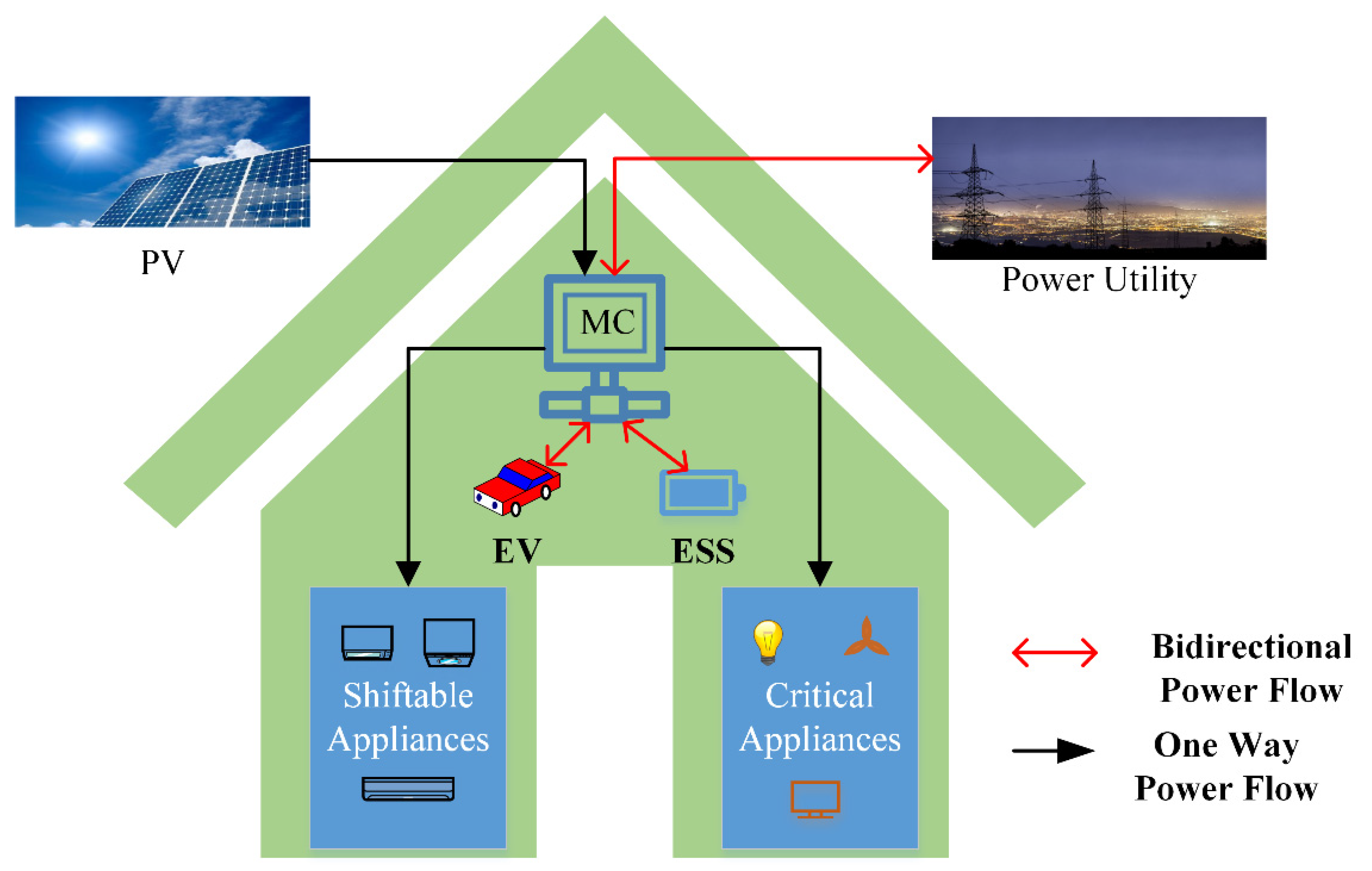
Figure 1. HEMS architecture.
Energies 14 08557 g001
Figure 2. Charging and discharging schemes of EV and ESS.
Energies 14 08557 g002
Figure 3. Flow chart of the BPSO.
Energies 14 08557 g003
Figure 4. (A) RTP of utility and (B) PV generated output power.
Energies 14 08557 g004
Figure 5. Baseline schedule of appliances.
Energies 14 08557 g005
Figure 6. Scheduling of Appliances with RTP.
Energies 14 08557 g006
Figure 7. Scheduling of the appliance with RTP and PV.
Energies 14 08557 g007
Figure 8. Charging and discharging of EV according to the charging/discharging scheme.
Energies 14 08557 g008
Figure 9. Charging and discharging of ESS according to the charging/discharging scheme.
Energies 14 08557 g009
Figure 10. Power exchange between the home and grid in a single objective problem.
Energies 14 08557 g010
Figure 11. Cost of the different scheduling schemes.
Energies 14 08557 g011
Figure 12. Comparison of cost, PAR, and DI.
Energies 14 08557 g012
Figure 13. Load demand curve of the three considered cases.
Energies 14 08557 g013
Figure 14. Power exchange between home and grid in multi-objective problem.
Energies 14 08557 g014
Table 1. Comparison of different studies.
PaperOptimization AlgorithmScheduling Home AppliancesProblem ObjectivesIntegrationCharging and Discharging Scheme of EV/ESSH2G CapabilityV2G/V2H CapabilitySelling Capability
Min CostMin DIMin PARRESESSEV
[5]ELPSO
[6]MILP
[7]GA
[8]BPSO
[9]RBA
[10]RBA
[11]MINLP
[12]MILP
[13]PSO
[14]Fuzzy logic
[15]DP and RBA
[16]HGPO, ACO, GA
[17]MILP
[18]DFA & AHP
[19]RBA
[21]MILP & RBA
[22]LP
[23]simplex
[24]MH & RBA
[25]MILP
[27]Two stage RBA
[29]LP
Out proposed workBPSO
Table 2. Appliance description.
AppliancesRated Power (kwh)Time Duration for Appliances ON (h)Baseline Operating Time Span
Schedulable applianceDishwasher (DW)2.5409:00–11:00 & 20:00–22:00
Washing machine (WM)3209:00–11:00
Spine dryer (SD)2.5213:00–15:00
Cooker hub (CH)3209:00–10:00 & 19:00–20:00
Cooker oven (CO)5213:00–14:00 & 20:00–21:00
Microwave (MW)1.7210:00–11:00 & 20:00–21:00
Laptop (LT)0.1610:00–13:00 & 18:00–21:00
Desktop (DT)0.3610:00–13:00 & 18:00–21:00
Vaccum cleaner (VC)1.2210:00–12:00
Real-Time appliance (RT)Fan0.21406:00pm–8:00 am
Light0.1806:00 p.m.–12:00 a.m. &
06:00 a.m.–8:00 a.m.
Television0.2408:00 p.m.–12:00 a.m.
Refrigerator12400:00 a.m.–12:00 a.m.
Table 3. ESS and EV parameter.
ESS ParameterEV Parameter
S O C E S S m a x (kWh)6 S O C E V m a x (kWh)10
S O C E S S i n t (kWh)3 S O C E V i n t (kWh)2
P E S S c h a r g e (kW)4 P E V c h a r g e (kW)4
P E S S d c h a r g e (kW)−4 P E V d c h a r g e (kW)−4
η E S S c h a r g e / η E S S d c h a r g e 0.92 η E V c h a r g e / η E V d c h a r g e 0.92
Table 4. Different cases for multi-objective problem.
CasesW1W2W3Cost (Cents)PARDI
Case-1100170.413.030896
Case-21205191.462.572780
Case-314020205.142.326068
Publisher’s Note: MDPI stays neutral with regard to jurisdictional claims in published maps and institutional affiliations.