Abstract
The cold start property is one of the main factors restricting the fuel cell application in the automotive field. The constant voltage cold start method of the fuel cell works under low start voltage and produces high heat, which can shorten the start-up time of the fuel cell at low temperature and has the opportunity to be applied to fuel cell vehicles. Meanwhile, in the constant voltage cold start mode, the fuel cell needs to operate under a large current, and more water is generated during the start-up process. Thus, the optimization of operating conditions for the constant voltage cold start is particularly important. However, there are relatively few studies on the optimization of operating conditions for the constant voltage cold start with a single-cell voltage less than 0.3 V. In this work, the cold start experiment of the fuel cell with constant voltage is carried out. According to the cold start experiment, the different cold start voltage, back-pressure, and the inlet flow rate are examined. Based on the experiment data, the operating conditions have a great influence on the cold start property of the fuel cell and the optimized operating conditions of the constant voltage cold start are obtained.
1. Introduction
Proton exchange membrane fuel cell (PEMFC) is one of the efficient hydrogen energy utilization devices, which has many advantages such as high efficiency and environmental protection and is expected to be applied in the automotive field [1,2,3,4]. However, the cold start property can affact its application in the automotive field [5,6].
In the subfreezing temperature environment, the water generated by the oxygen-reduction reaction is easily converted into ice, which could block the gas transmission, resulting in the cold start failure [7]. Therefore, previous research mainly focused on the freezing mechanism and cold start process to solve these problems. Huo et al. [8] considered the mechanism of the phase transition and water transport in the cold start process and indicated that most of the water in the cathode catalytic layer (CL) was more likely to freeze. Hirakata et al. [9] added a hydrophilic layer to the gas diffusion layer (GDL), proving that the hydrophilic layer could enhance the movement of water from the CL to the GDL and effectively inhibit the water icing in the CL. Zhu et al. [10] found that the pressure drop in a single variable section serpentine flow field was large, which could inhibit icing and had strong cold start characteristics in fuel cells. Knorr et al. [11] adopted the methanol–water mixture as antifreeze for the PEMFC and found that the durability of the fuel cell improved significantly after the use of antifreeze.
Besides, the rapid start of the PEMFC in the subzero temperature environment by the control strategy is also the main research direction, such as the assisted cold start and cold start without auxiliary. On one hand, the assisted cold start refers to a method of fast start with auxiliary equipment other than necessary components of the fuel cell system. At the moment, the common auxiliary cold start methods include electric heating [5], gas heating [12,13], coolant heating [14,15], and internal catalytic hydrogen–oxygen reaction [16,17]. However, the auxiliary cold start method greatly extends the complexity of the PEMFC system, which is not conducive to its application in the automotive field [18]. On the other hand, the choice of the cold start mode is also an efficient way to upgrade the cold start-up capability of the PEMFC [19]. Generally, constant current mode [20,21], constant voltage mode [22,23], and constant power mode [24,25] are considered to be effective cold start modes without auxiliary. Among them, the PEMFC usually works at a low starting voltage in constant voltage mode (less than 0.3 V) and generates a high amount of heat, which can reduce the start time of the PEMFC to reach 0 °C [26,27]. Therefore, when the constant voltage mode is adopted, the fuel cell can start rapidly at a low temperature. Meanwhile, the constant voltage mode is expected to be used in fuel cell vehicles.
As for the cold start operating condition, a lot of research have been investigated on purge conditions, cold start temperature, and so on [12,28,29]. Nevertheless, in the constant voltage cold start mode, the fuel cell needs to operate under a large current, and more water is generated during the start-up process. If the cold start operating conditions are not appropriate, the generated water will freeze and hinder the cold start of the PEMFC. Thus, the optimization of the operating conditions, such as cold start voltage, back-pressure, and the inlet flow rate, for the constant voltage cold start is particularly important. However, there were relatively few studies on the optimization of operating conditions for the constant voltage cold start, especially for the voltage lower than 0.3 V in the single-cell.
In this work, the cold start experiment of the PEMFC with constant voltage is carried out. According to the cold start experiment, the different cold start voltage, back-pressure, and the inlet flow rate are examined. Based on experimental data, the impact of the operating conditions on the cold start-up of the PEMFC and the optimized operating conditions of the constant voltage cold start are obtained.
2. Experimental
2.1. Single Cell Assembly and Cold Start Experimental Test Platform
In this work, the experiment was performed on a single cell and a commercial membrane electrode assembly (MEA) was used in the single cell test. The main parameters of the PEMFC single cell and MEA were displayed in Table 1 andTable 2, respectively.

Table 1.
The parameters of the proton exchange membrane fuel cell (PEMFC) single cell.
Table 2.
The parameters of the membrane electrode assembly (MEA).
The reaction gas and the operating parameters such as backpressure, load, gas flow, and humidity of the PEMFC were controlled by the fuel cell test platform (PEMTest50, Hephas: Taiwan, China). Additionally, Figure 1 exhibited the schematic diagram of the test platform. The cold start experiment was carried out by using a climate chamber to simulate the subzero environment and the temperature range was −40–150 °C. To certify that the reaction gas temperature entering the fuel cell was consistent with the temperature set in the climate chamber, two 2 m cooling coils were added to the front end of the fuel cell in the climate chamber.
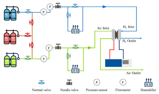
Figure 1.
The schematic diagram of the fuel cell test platform.
2.2. PEMFC Activation Process
Generally, the MEA was demanded to activate to achieve optimum performance before the cold start experiment. In the activation process, the working temperature of the PEMFC was 75 °C and the main operating parameters were shown in Table 3. The output performance of the PEMFC was controlled by the electronic load, running for 30 s at 0.8 V and 600 s at 0.3 V for a period of 4 h. After that, the activation of the PEMFC was finished.
Table 3.
Operating parameters of the PEMFC activation process.
2.3. Cold Start Experiment Procedure
Before the cold start experiment, the dry nitrogen purged into the anode and cathode of the PEMFC for 2 h with a flow rate of 2 L·min−1 and 5 L·min−1 respectively to ensure that the MEA would not be damaged by water freezing. Then, the PEMFC was put into the climate chamber, which was set to −5 °C, and the temperature was kept constant for 4 h. The gas humidity was 0% and other operating parameters of the PEMFC cold start were displayed in Table 4. When the temperature of the fuel cell reached 0 °C, the cold start was considered successful.
Table 4.
Operating parameters of the PEMFC cold start in a different case.
2.4. Electrochemical Impedance Spectroscopy Measurement
The Autolab PGSTAT 302N electrochemical workstation (Metrohm, Heirishau, Switzerland) was prepared to measure the electrochemical impedance spectroscopy (EIS) of the PEMFC. Additionally, a two-electrode cell with an anode as a reference electrode was used in the measurement. After that, the ohmic resistance in the PEMFC could also be obtained. Meanwhile, the galvanostatic mode was chosen in the impedance measurements with a frequency range of 10 kHz to 0.1 Hz and an AC signal with 10% DC amplitude was selected to obtain the linear response of the system. Additionally, the operating parameters of the PEMFC for the EIS test was exhibited in Table 5.
Table 5.
Operating parameters of the PEMFC for the electrochemical impedance spectroscopy (EIS) test.
3. Results and Discussion
In this section, the different cold start voltage, back-pressure, and the inlet flow rate were studied to obtain an optimized operating condition of the constant voltage cold start. Based on the optimized operating condition, the start time of the PEMFC reaching 0 °C could be shortened.
3.1. Impact of the Fuel Cell Voltage during Cold Start
To study the impact of different cell cold start voltages on the cold start property of the PEMFC, 0.1 V, 0.15 V, 0.2 V, 0.25 V, and 0.3 V were respectively used as the constant cell cold start voltages to the experiments. Case 1 to Case 5 was the experimental operating parameters, which were shown in Table 4.
Figure 2 exhibited the curve of the current and temperature during the cold start of the PEMFC at different cell voltages. As can be seen from Figure 2, under the constant voltage mode, the lower the start-up voltage is, the higher the peak current of the PEMFC becomes. When the PEMFC started at 0.1 V, the peak current in the whole cold start process was 24.99 A, which was higher than 24.19 A at 0.15 V, 22.89 A at 0.2 V, 22.2 A at 0.25 V, and 21.06 A at 0.3 V.
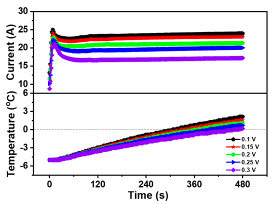
Figure 2.
Impact of the different start-up voltages on cold start property of the PEMFC.
Although the current varied in value, the overall current trend was very similar. During the first stage of the cold start, the current value of the PEMFC rose rapidly to the peak level. As the internal temperature of the PEMFC was still below freezing, the liquid water produced by the electrochemical reaction was easy to freeze. Thus, the produced ice covered the part of the area of the CL and the GDL, which led to the hinder of the electrochemical reaction, resulting in a temporary decrease of the PEMFC current after reaching the peak value. However, in this process, the heat generated by PEMFC was greater than the sum of the heat dissipated by PEMFC and the heat taken away by exhaust gas, the temperature continued to rise even as the current decreased. As the reaction progresses, the increase of the heat generation promoted the internal heating and catalytic activity of the PEMFC, the current increased steadily and the cold start was successful at last when the temperature of the PEMFC rose above 0 °C.
Moreover, the experimental results also displayed that the successful cold start time of the PEMFC declined with the decrease of start-up voltage. Additionally, in the five cold start experiments, the start time of the PEMFC from −5 to 0 °C was 305.5 s at 0.1 V, 328.1 s at 0.15 V, 360.3 s at 0.2 V, 399.4 s at 0.25 V, and 457.2 s at 0.3 V. It could be suggested that the PEMFC could generate more heat per unit time, making it possible to start successfully in a shorter time. Compared with other voltages, the cold start property of the PEMFC at 0.1 V was the best. Therefore, 0.1 V was selected as the start-up voltage for the constant voltage cold start and was used as the start-up voltage in subsequent experiments.
3.2. Impact of the Back-Pressure During Cold Start
The back-pressure is one of the key factors in the operating conditions, which can affect the property of the PEMFC. The concentration of the reaction gas can be increased by increasing the back-pressure, especially the concentration of air (oxygen) in the cathode, and increased the exchange current density of the electrode reaction, leading to the speed-up of the reaction [30]. Therefore, it is necessary to study the impact of the back-pressure on the cold start property of the PEMFC.
In this section, the relationship between back-pressure and the PEMFC property was investigated by adjusting the back-pressure valve of the test platform. The EIS of the PEMFC before the cold start was compared under different back-pressure, which was shown in Figure 3. The anode and cathode working back-pressure of the PEMFC were set to 0 bar, 0.5 bar, and 1 bar, respectively. The results suggested that the whole impedance curve shifted to the left with the enlargement of the back-pressure, and the impedance spectrum decreased with the increment of the back-pressure. The ohmic impedance of the MEA was 5.43 mΩ when both the anode and cathode back-pressure was 0 bar. When the back-pressure increased to 0.5 bar, the ohmic impedance decreased to 4.96 mΩ, while the ohmic impedance was the smallest at 1 bar, which was 4.63 mΩ. As the ohmic impedance was related to the water content in the proton exchange membrane (PEM), the ohmic impedance decreased, indicating that the water content of the PEM increased. Therefore, increasing the back-pressure could promote the movement of the gas perpendicular to the flow channel and be beneficial to the improvement of fuel cell property.
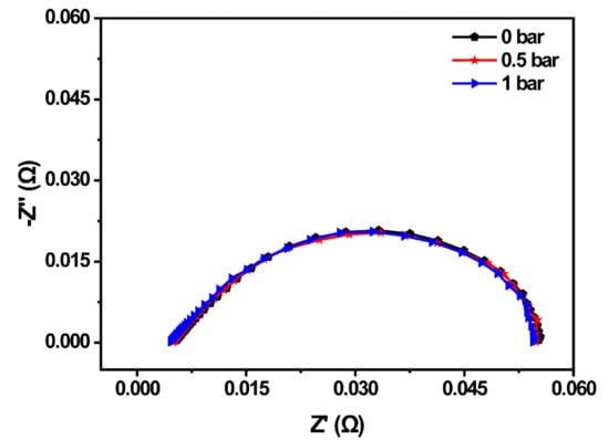
Figure 3.
EIS spectrum of the PEMFC under different back-pressures.
To further explore the impact of back-pressure on the cold start property of the PEMFC, Case 1, Case 6, and Case 7 were selected as experimental operation parameters, as shown in Table 4. Additionally, the curve of the current and temperature of the PEMFC during the cold start-up process under different back-pressures was shown in Figure 4. Under the temperature of −5 °C, the start-up time of the PEMFC at 0 bar was 305.5 s with a peak current of 24.99 A. Meanwhile, the start-up time of the PEMFC at 0.5 bar was 274.0 s with a peak current of 27.53 A, indicating that the reaction rate of the PEMFC could be enhanced by appropriately increasing the back-pressure, which could increase the current of the PEMFC at the same working voltage. Therefore, the cold start-up speed of the PEMFC was accelerated. However, the cold start of the PEMFC failed at 1 bar even though the peak current reached 29.06 A, which was the highest among these three cases. The reason might be that high current produced more water, while high back-pressure reduced the gas flow, making it difficult to eject the generated water. Moreover, the accumulated water led to flooding inside the PEMFC, which prevented the electrochemical reaction. As a result, the heat generated could not meet the requirements of the cold start, which caused the freezing of the MEA. Therefore, the back-pressure could enhance the cold start property of the PEMFC, but excessive back-pressure could also be detrimental to the cold start property of the PEMFC. According to the above analysis, the anode and cathode back-pressure of the PEMFC was both set to 0.5 bar to ensure the best cold start-up property of the PEMFC at low temperature.
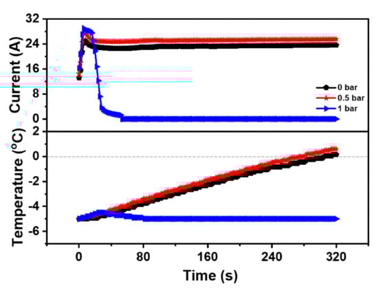
Figure 4.
Impact of the different back-pressure on the cold start property of the PEMFC.
3.3. Impact of the Inlet Gas Flow Rate during Cold Start
To survey the impact of inlet gas flow rate on the cold start property of the PEMFC, the anode and cathode gas flow rates of the PEMFC were set to 400 mL·min−1 and 900 mL·min−1, 800 mL·min−1 and 1800 mL·min−1, 1200 mL·min−1 and 2700 mL·min−1, and 1600 mL·min−1 and 3600 mL·min−1, respectively. Case 1, Case 8, Case 9, and Case 10 were the experimental operating parameters, which were shown in Table 4. Additionally, the impact of different inlet gas flow on the cold start property of the PEMFC was revealed in Figure 5 with the gas flow rate mentioned above. It was obvious that the peak current of Case 1, Case 8, Case 9, and Case 10 was 24.99 A, 25.91 A, 27.46 A, and 28.54 A respectively, which means the electrochemical reaction could be accelerated by increasing the gas flow rate of the PEMFC. Among these four cases, Case 1 (400 mL·min−1 and 900 mL·min−1), Case 8 (800 mL·min−1 and 1800 mL·min−1), and Case 9 (1200 mL·min−1 and 2700 mL·min−1) were successfully started at the low temperature and the required start-up time was 305.5 s, 291.3 s, and 257.4 s, respectively. In other words, the cold start time of the PEMFC was shortened and the cold start property of the PEMFC was improved after increasing the inlet gas flow rate. The results could be declared that the increase of the inlet gas flow rate could enhance the supply of the reaction gas, accelerate the movement of the reaction gas, and increase the current of the PEMFC [31]. Meanwhile, a higher current could provide more heat to the PEMFC cold start. On the other hand, the gas velocity in the flow channel raised with a large gas flow rate, and the produced water in the PEMFC could be brought out by the high-speed gas, preventing the CL and the GDL covered by ice and ensuring the smooth transmission of the reaction gas. However, the impact of the factor on the cold start property of the PEMFC was limited. When the anode and cathode gas flow rate of the PEMFC enlarged to 1600 mL·min−1 and 3600 mL·min−1, the cold start of the PEMFC failed. Although electrochemical reactions of the PEMFC occurred rapidly at a high gas flow rate, it was difficult for the PEMFC to maintain the temperature rise due to high gas velocity and rapid heat loss. Hence, the produced water was frozen without enough heat, which coated the CL and GDL, impeding the transfer of the reaction gas and the electrochemical reaction. Based on the experimental results in Figure 5, the anode and cathode inlet gas flow rates of the PEMFC were 1200 mL·min−1 and 2700 mL·min−1.
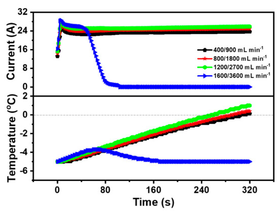
Figure 5.
Impact of different inlet gas flow on cold start property of the PEMFC.
4. Conclusions
In this work, the cold start experiment of the PEMFC with constant voltage was carried out. During the cold start experiment, the impact of the operating conditions on the cold start-up of the PEMFC, such as cold start voltage, back-pressure, and the inlet flow rate was investigated. Based on experimental data, the operating conditions had a great influence on the cold start property of the fuel cell and the optimized operating conditions of the constant voltage cold start were obtained. Meanwhile, the conclusions were drawn as follow:
- (1)
- Based on the constant voltage cold start, the peak current of the PEMFC was the highest when the start-up voltage was 0.1 V. Additionally, the heating rate was faster than that when the start-up voltage was 0.15 V, 0.2 V, 0.25 V, and 0.3 V, indicating that the lower start-up voltage could accelerate the heat production of the PEMFC and develop its cold start property at low temperature. Additionally, the optimized cold start voltage of the PEMFC was 0.1 V.
- (2)
- The increase of the back-pressure could promote the movement of the gas perpendicular to the flow channel, increase the concentration of the reaction gas, accelerate the electrochemical reaction, and enhance the cold start property of the PEMFC at low temperature. However, excessive back-pressure could also reduce the gas flow and made it difficult to drain the generated water, which was detrimental to the cold start property of the PEMFC. Additionally, the optimized cold start back-pressure of the PEMFC was 0.5 bar.
- (3)
- The inlet flow rate was a significant factor affecting the cold start property of the PEMFC. The increase of the inlet gas flow rate could enhance the supply of the reaction gas, augment the current of the PEMFC and accelerate the temperature rise of the PEMFC. However, it is difficult for the PEMFC to maintain the temperature rise due to the high inlet flow rate and rapid heat loss. Thus, the optimized cold start inlet flow rate of the PEMFC in the anode and cathode was 1200 mL·min−1 and 2700 mL·min−1, respectively.
Author Contributions
Conceptualization, Y.Y. and T.M.; Data curation, Y.Y.; Methodology, Y.Y.; Project administration, T.M.; Formal analysis, Y.Y. and W.L.; Investigation, Y.Y.; Resources, T.M.; Supervision, T.M.; Validation, Y.Y.; Visualization, Y.Y.; Writing—original draft, Y.Y.; Writing—review and editing, B.D., W.L. and N.Y. All authors have read and agreed to the published version of the manuscript.
Funding
This work was funded by the National Natural Science Foundation of China (No. 52077157) and the Key-Area Research and Development Program of Guangdong Province (No. 2019B090909002).
Institutional Review Board Statement
Not applicable.
Informed Consent Statement
Not applicable.
Data Availability Statement
Not applicable.
Conflicts of Interest
The authors declare no conflict of interest. The funders had no role in the design of the study; in the collection, analyses, or interpretation of data; in the writing of the manuscript, or in the decision to publish the results.
References
- Liu, Z.; Pei, M.; He, Q.; Wu, Q.; Jackson, L.; Mao, L. A novel method for polymer electrolyte membrane fuel cell fault diagnosis using 2D data. J. Power Sources 2021, 482, 228894. [Google Scholar] [CrossRef]
- Xie, X.; Zhu, M.; Wu, S.; Tongsh, C.; Sun, X.; Wang, B.; Park, J.W.; Jiao, K. Investigation of mechanical vibration effect on proton exchange membrane fuel cell cold start. Int. J. Hydrogen Energy 2020, 45, 14528–14538. [Google Scholar] [CrossRef]
- Liu, Z.; Chen, J.; Liu, H.; Yan, C.; Hou, Y.; He, Q.; Zhang, J.; Hissel, D. Anode purge management for hydrogen utilization and stack durability improvement of PEM fuel cell systems. Appl. Energy 2020, 275, 115110. [Google Scholar] [CrossRef]
- Sun, L.; Jin, Y.; You, F. Active disturbance rejection temperature control of open-cathode proton exchange membrane fuel cell. Appl. Energy 2020, 261, 114381. [Google Scholar] [CrossRef]
- Zhou, Y.; Luo, Y.; Yu, S.; Jiao, K. Modeling of cold start processes and performance optimization for proton exchange membrane fuel cell stacks. J. Power Sources 2014, 247, 738–748. [Google Scholar] [CrossRef]
- Wei, L.; Dafalla, A.M.; Jiang, F. Effects of reactants/coolant non-uniform inflow on the cold start performance of PEMFC stack. Int. J. Hydrogen Energy 2020, 45, 13469–13482. [Google Scholar] [CrossRef]
- Jiao, K.; Alaefour, I.E.; Karimi, G.; Li, X. Cold start characteristics of proton exchange membrane fuel cells. Int. J. Hydrogen Energy 2011, 36, 11832–11845. [Google Scholar] [CrossRef]
- Huo, S.; Jiao, K.; Park, J.W. On the water transport behavior and phase transition mechanisms in cold start operation of PEM fuel cell. Appl. Energy 2019, 233–234, 776–788. [Google Scholar] [CrossRef]
- Hirakata, S.; Hara, M.; Kakinuma, K.; Uchida, M.; Tryk, D.A.; Uchida, H.; Watanabe, M. Investigation of the effect of a hydrophilic layer in the gas diffusion layer of a polymer electrolyte membrane fuel cell on the cell performance and cold start behaviour. Electrochim. Acta 2014, 120, 240–247. [Google Scholar] [CrossRef]
- Zhu, Y.; Lin, R.; Jiang, Z.; Zhong, D.; Wang, B.; Shangguan, W.; Han, L. Investigation on cold start of polymer electrolyte membrane fuel cells with different cathode serpentine flow fields. Int. J. Hydrogen Energy 2019, 44, 7505–7517. [Google Scholar] [CrossRef]
- Knorr, F.; Sanchez, D.G.; Schirmer, J.; Gazdzicki, P.; Friedrich, K.A. Methanol as antifreeze agent for cold start of automotive polymer electrolyte membrane fuel cells. Appl. Energy 2019, 238, 1–10. [Google Scholar] [CrossRef]
- Yan, Q.; Toghiani, H.; Lee, Y.-W.; Liang, K.; Causey, H. Effect of sub-freezing temperatures on a PEM fuel cell performance, startup and fuel cell components. J. Power Sources 2006, 160, 1242–1250. [Google Scholar] [CrossRef]
- Jiao, K.; Li, X. Three-dimensional multiphase modeling of cold start processes in polymer electrolyte membrane fuel cells. Electrochim. Acta 2009, 54, 6876–6891. [Google Scholar] [CrossRef]
- Sundaresan, M.; Moore, R.M. Polymer electrolyte fuel cell stack thermal model to evaluate sub-freezing startup. J. Power Sources 2005, 145, 534–545. [Google Scholar] [CrossRef]
- Ahluwalia, R.K.; Wang, X. Rapid self-start of polymer electrolyte fuel cell stacks from subfreezing temperatures. J. Power Sources 2006, 162, 502–512. [Google Scholar] [CrossRef]
- Genorio, B.; Strmcnik, D.; Subbaraman, R.; Tripkovic, D.; Karapetrov, G.; Stamenkovic, V.R.; Pejovnik, S.; Markovic, N.M. Selective catalysts for the hydrogen oxidation and oxygen reduction reactions by patterning of platinum with calix [4] arene molecules. Nat. Mater. 2010, 9, 998–1003. [Google Scholar] [CrossRef]
- Sun, S.; Yu, H.; Hou, J.; Shao, Z.; Yi, B.; Ming, P.; Hou, Z. Catalytic hydrogen/oxygen reaction assisted the proton exchange membrane fuel cell (PEMFC) startup at subzero temperature. J. Power Sources 2008, 177, 137–141. [Google Scholar] [CrossRef]
- Amamou, A.A.; Kelouwani, S.; Boulon, L.; Agbossou, K.A. Comprehensive review of solutions and strategies for cold start of automotive proton exchange membrane fuel cells. IEEE Access 2016, 4, 4989–5002. [Google Scholar] [CrossRef]
- Oberholzer, P.; Boillat, P.; Siegrist, R.; Perego, R.; Kästner, A.; Lehmann, E.; Scherer, G.G.; Wokaun, A. Cold-Start of a PEFC visualized with high resolution dynamic in-plane neutron imaging. J. Electrochem. Soc. 2011, 159, B235–B245. [Google Scholar] [CrossRef]
- Jiang, F.; Wang, C.-Y.; Chen, K.S. Current ramping: A strategy for rapid start-up of PEMFCs from subfreezing environment. J. Electrochem. Soc. 2010, 157, B342–B347. [Google Scholar] [CrossRef]
- Luo, Y.; Guo, Q.; Du, Q.; Yin, Y.; Jiao, K. Analysis of cold start processes in proton exchange membrane fuel cell stacks. J. Power Sources 2013, 224, 99–114. [Google Scholar] [CrossRef]
- Jiang, F.; Wang, C.-Y. Potentiostatic start-up of PEMFCs from subzero temperatures. J. Electrochem. Soc. 2008, 155, B743–B751. [Google Scholar] [CrossRef]
- Jiao, K.; Li, X. Cold start analysis of polymer electrolyte membrane fuel cells. Int. J. Hydrogen Energy 2010, 35, 5077–5094. [Google Scholar] [CrossRef]
- Thounthong, P.; Raël, S.; Davat, B. Control strategy of fuel cell/supercapacitors hybrid power sources for electric vehicle. J. Power Sources 2006, 158, 806–814. [Google Scholar] [CrossRef]
- Du, Q.; Jia, B.; Luo, Y.; Chen, J.; Zhou, Y.; Jiao, K. Maximum power cold start mode of proton exchange membrane fuel cell. Int. J. Hydrogen Energy 2014, 39, 8390–8400. [Google Scholar] [CrossRef]
- Jiao, K.; Li, X. Effects of various operating and initial conditions on cold start performance of polymer electrolyte membrane fuel cells. Int. J. Hydrogen Energy 2009, 34, 8171–8184. [Google Scholar] [CrossRef]
- Amamou, A.; Kandidayeni, M.; Boulon, L.; Kelouwani, S. Real time adaptive efficient cold start strategy for proton exchange membrane fuel cells. Appl. Energy 2018, 216, 21–30. [Google Scholar] [CrossRef]
- Kong, I.M.; Jung, A.; Kim, B.J.; Baik, K.D.; Kim, M.S. Experimental study on the start-up with dry gases from normal cell temperatures in self-humidified proton exchange membrane fuel cells. Energy 2015, 93, 57–66. [Google Scholar] [CrossRef]
- Jia, L.; Tan, Z.; Kang, M.; Zhang, Z. Experimental investigation on dynamic characteristics of proton exchange membrane fuel cells at subzero temperatures. Int. J. Hydrogen Energy 2014, 39, 11120–11127. [Google Scholar] [CrossRef]
- Zhang, J.; Song, C.; Zhang, J.; Baker, R.; Zhang, L. Understanding the effects of backpressure on PEM fuel cell reactions and performance. J. Electroanal. Chem. 2013, 688, 130–136. [Google Scholar] [CrossRef]
- Liu, Z.; Mao, Z.; Wu, B.; Wang, L.; Schmidt, V.M. Current density distribution in PEFC. J. Power Sources 2005, 141, 205–210. [Google Scholar] [CrossRef]


Publisher’s Note: MDPI stays neutral with regard to jurisdictional claims in published maps and institutional affiliations. |
© 2021 by the authors. Licensee MDPI, Basel, Switzerland. This article is an open access article distributed under the terms and conditions of the Creative Commons Attribution (CC BY) license (http://creativecommons.org/licenses/by/4.0/).