Article

A Robust Nonlinear Controller for PMSG Wind Turbines †

by
Nicholas Hawkins
1,* and
Michael L. McIntyre
2
1
Engineering Fundamentals, University of Louisville, Louisville, KY 40292, USA
2
Electrical and Computer Engineering, University of Louisville, Louisville, KY 40292, USA
*
Author to whom correspondence should be addressed.
This paper is an extended version of our paper published in 2020 American Controls Conference, Denver, CO, USA, 1–3 July2020; pp. 3467–3472.
Energies 2021, 14(4), 954; https://doi.org/10.3390/en14040954
Submission received: 18 January 2021 / Revised: 2 February 2021 / Accepted: 7 February 2021 / Published: 11 February 2021
(This article belongs to the Special Issue Advanced Control Applications for Electrical Energy Systems)

Abstract

:
In this paper, a nonlinear backstepping controller is proposed to manage the performance of a full-variable permanent magnet synchronous generator wind turbine. This nonlinear controller achieves a rotational speed objective for the generator and is validated through Lyapunov-based stability analysis. Additionally, this objective is accomplished without a measurement for wind speed that influences the wind torque. The proposed scheme is compared to a typical linear controller through simulation results. Simulation tests are performed to compare the response time and average error of each controller in both a drastic and realistic dynamic wind environment. These results demonstrate that the proposed controller is far more robust to wind turbulence than traditional control schemes. The simulation results of this study indicate a 1000% increase in response time and 3000% decrease in average controller error.

1. Introduction

Since the late twentieth century, electricity generated from wind energy has been growing substantially. In 1996, worldwide wind energy conversion systems (WECSs) had an installed capacity of roughly 6 GW, which increased to 74 GW in 2006, 283 GW in 2012, and 624 GW in 2019 [1,2]. This growth within the last decade has continued at an increasing rate [3]. In the United States alone, wind energy is increasingly consumed compared to solar and geothermal sources and is nearly as widely used as hydroelectric [4]. Wind turbines are also economically attractive, potentially creating over 600,000 jobs and saving the US utility consumer $280 billion by 2050 [5].
In the efforts to attain a full-variable speed WECS, the Type 4 configuration was developed, as seen in Figure 1. This topology typically utilizes a permanent magnet synchronous generator (PMSG) followed by a series of power converters—a rectifier followed by an inverter—that connects to the grid. This means that, unlike Type 3 WECSs (those that utilize double-fed induction generators), 100% of the power generated in this system is run through the power converters [6]. Type 4 systems have only recently gained popularity due to increased switching component performance and are advantageous due to their full controllability [7,8]. The use of PMSG in particular for Type 4 configurations is common due to their higher efficiency and better speed range than most other machines [8].
The control of the PMSG has been studied widely for WECS applications, though the development of these control schemes took place before Type 4 configurations. Traditionally, PMSGs have been controlled using a linear control method called vector control. This scheme utilizes a cascaded architecture of proportional-integrator (PI) controllers to manage the speed of the machine. Typically, this is done through the dq reference frame, and the speed control is the outer control loop that provides a reference for the inner q-axis current control loop [9,10,11,12]. In these schemes, the d-axis current is controlled separately.
While vector control is well known and widely used, it is not the most efficient way to control PMSG systems. Due to the use of PI controllers, vector control is particularly weak regarding system nonlinearities and rapidly changing dynamics, such as large wind gusts, which require much a faster response from controllers.
Attempts have been made to improve the performance of vector controllers with augmented linear schemes. Among these are controllers utilizing feedforward techniques to reduce the computational load on the integrators of the PI controllers [13]. Other linear controllers attempt to simplify the control architecture through the elimination of the outer speed loop [14]. In this scheme, the q-axis current reference is directly calculated, which attempts to reduce response time.
Additionally, there are controllers that employ the use of proportional-resonant (PR) controllers, which behave similarly to PI controllers. The primary advantage to using a PR controller is that it more easily obtains a zero steady-state error for tracking sinusoidal-like trajectories [15]. As wind speeds often oscillate when turbulent, it is easy to conject that a speed trajectory for a PMSG WECS is logical.
Another method used to augment vector control strategies is the utilization of fuzzy logic alongside the PI controllers. The purpose of the fuzzy logic controllers is to provide more effective reference values to the front-end of the PI controllers, which improves response time by easing the work being performed by the integrators [16,17].
A considerable drawback of these control schemes is the application of a linear structure to a nonlinear system. PMSGs behave nonlinearly, so the strategy of linearizing them around small operational windows tends to yield poor results, especially as erratic weather conditions make staying in such a window nearly impossible [18].
One approach being used to minimize the negative effects of system uncertainties is the use of optimal singular adaptive observers to determine unknown system parameters [19]. This observer is used to feed state information to a vector controller. Additionally, this approach is able to observe the initial state vector of the system should measurements be withheld.
Transitioning away from linear strategies, improvements have been made by utilizing nonlinear schemes such as the sliding-mode control [20,21,22], which targets the issue of parameter uncertainties. Sliding mode controllers manage uncertainties through variable structure control and use a model-based approach to improve dynamic response times, oftentimes utilizing backstepping techniques [23]. Comparison to the vector control shows that sliding mode controllers reduce overshoot and response times when there is a shift in operation point [23,24].
Another method of nonlinear control seeks to use linearization techniques alongside robust control methods to minimize the issues caused by system nonlinearities [25,26,27]. These controllers utilize a known equilibrium point to significantly reduce the complexity of model equations, assuming the system always operates near that known point. This method then creates a transfer function from the reduced nonlinear model.
The primary issue with these schemes is the required mechanical knowledge needed to function correctly. There are numerous problems that occur when a turbine’s mechanical efficiency is approximated, the largest being that such approximations only apply to specific turbines and cannot be accurately extrapolated to any such machine. Additionally, the mathematical nature of these efficiency equations vary between sources [28].
The model predictive control is a method that has come about more recently to mitigate the issues with typical nonlinear controllers. The model predictive control shifts the unknown model until the controller functions as intended [29,30]. This means that as a system point of operation shifts (in this context, due to changing wind speeds), this control scheme changes its reference model to account for such changes.
Recent approaches at PMSG control utilize fuzzy logic control schemes. Fuzzy logic uses model rules to manage a system through uncertainties [31,32]. The issue with these types of control approaches, however, are these rules. More rules are needed to gain higher effectiveness, but this also causes controller sluggishness with respect to response times. This means that fuzzy logic controllers tend to sacrifice accuracy for computational speed (or vice versa).
While not covered in this work, Type 4 wind turbine configurations also sometimes utilize squirrel cage induction generators (SCIGs) in place of PMSGs. The use of a SCIG over a PMSG is less popular due to the need to manage rotor flux in addition to the primary objective of speed control [2]. However, control schemes are very similar between the two machines, with vector control and some nonlinear methods being utilized [33,34].
In this paper, a model-based nonlinear controller is proposed to compensate for the unknown time-varying effects of the wind torque. This nonlinear method is robust to uncertainty through the utilization of a high-gain term. With this in mind, the proposed controller manages the rotational speed of the PMSG with high precision and rapid dynamic response times. As previously mentioned, other nonlinear approaches have used backstepping approaches similar to the one proposed here [23]. However, previous approaches require full model knowledge or are otherwise ineffective at managing structural uncertainties. This work is unique in that it manages the machine speed without knowledge of the wind torque, where other works require an estimation of this quantity. The proposed controller is intended to function through any range of machine and environmental parameters, which is a substantial improvement on both existing linear and nonlinear schemes.
This control scheme was expanded from the work presented in [35] by maintaining performance without the need for a wind speed measurement. Additionally, results were enhanced for more realistic wind turbine difficulties, and an industry standard vector controller was developed as a means of comparison.
The paper is organized as follows: Section 2 gives an overview of the mathematical system model; Section 3 provides the proposed controller framework; Section 4 provides controller validation through a Lyapunov stability analysis, and test results using a simulation platform; Section 5 gives concluding remarks, and the References section.

2. System Model

The mechanical subsystem of a PMSG WECS can be mathematically described as [21]
J ω ˙ + B ω + T L = ( 3 P 4 ) λ m I q .
The mechanical quantities are as follows: J is the combined system inertia, B is the damping ratio,   ω is the rotational speed (in rad/s) of the turbine shaft, and T L is the wind torque. There exist some electrical quantities in this subsystem, which are as follows: P is the number of generator poles, λ m is the generator flux, and I q is the q-axis generator current.
The torque T L can be defined utilizing the definition of rotational mechanical power as
T L P a e r o ω
where P a e r o is the incoming wind power at the blades. This is mathematically modelled as [21]
P a e r o 1 2 C p ρ A v 3
where ρ is the air density, A is the circular blade area, v is the wind speed, and C p ( λ , β ) [ 0 , 16 27 ] is the turbine’s power coefficient. This coefficient, or blade efficiency, is upper-bounded by the Betz limit and is a function of the blade angle β and the tip speed ratio λ . This tip speed ratio is described using [21]
λ = R ω v
where R is the blade radius. The coefficient C p is an incredibly nonlinear quantity. Additionally, it is not measurable in existing windmill control systems, and therefore there are numerous attempts at mathematically estimating this quantity, which are similar in structure but have nuanced differences [10,20,21,28,36,37].
To maximize the mechanical efficiency of a wind turbine, the desired speed is chosen based on an optimal tip speed ratio, i.e.,
ω d λ d v R
where λ d is the desired tip speed ratio. For the purposes of this work, (5) is used with a manually selected λ d .
Remark 1.
From the form of (5), it is apparent that such a method requires real-time measurement of the wind speed and knowledge of the optimal tip speed ratio. The need for this knowledge can be eliminated by utilizing commonly used maximum power point tracking (MPPT) methods [9,38], though this work aims to demonstrate controller tracking ability alone. Therefore, this work assumes for the purposes of speed trajectory planning that the wind speed is measurable. However, the subsequent controller itself does not assume a known wind speed, as seen in Remark 2.
The electrical subsystem of a PMSG system can be mathematically modelled in the rotating-reference frame as [21]
v d = R s I d P 2 ω L s I q + L s I ˙ d
v q = P 2 ω L s I d + R s I q + L s I ˙ q + λ m P 2 ω
where v d and v q are the generator voltages for the d-axis and q-axis, respectively, L s is the per-phase generator inductance, R s is the per-phase generator resistance, and I d is the d-axis generator current.

3. Proposed Controller

This controller’s objective is to manage the wind turbine’s rotational velocity ω ( t ) such that it follows a desired trajectory defined by ω d ( t ) . The control signal is manifested in the form of the dq voltages, which are controllable based on the connection of the turbine to some voltage infrastructure (i.e., utility, a micro-grid, etc.). If an appropriate velocity trajectory is chosen, this control scheme can ultimately be utilized to attain maximized power capture from the wind. Before a mathematical determination of this controller can begin, a series of assumptions must first be indicated.
Assumption 1.
The torque T L ( ω , v ) is an unknown quantity that varies with time and is bounded by a known function Ω ( ω )   | T L ( ω , v ) | , where Ω ( ω ) is continuously differentiable. Additionally, it is assumed that T L ( ω , v ) .
Assumption 2.
The turbine rotational speed ω ( t ) is measurable.
Assumption 3.
The generator voltages (control signals) and currents are all measurable and appropriately synchronized between the abc and dq frames.
Assumption 4.
The parameters A ,   J ,   B ,   P ,   λ m ,   L s , and R s are known a priori and are constant with respect to time.
Assumption 5.
The wind speed v is assumed to be unknown. However, an upper bound for the wind speed, v u p , is assumed to be known a priori and is constant with respect to time.
The control development starts with an error signal e ( t ) that is defined such that the goal of the controller is for e ( t ) to be bounded as t . This error is defined as
e ω d ω .
Next, a backstepping control objective is utilized to allow the terminal voltages— v d ( t ) and v q ( t ) —to be control inputs. This is accomplished through two additional error terms, defined as
η q I q I q d
n d I d I d d
where I q d ( t )   and     I d d ( t ) are the desired dq current signals. These additional error terms are defined such that the goal of the controller also includes that η q ( t )   and     η d ( t ) are bounded as t .

3.1. Speed Error Dynamics

The speed error described in (8) can be manipulated by taking the derivative and multiplying by J ; it can be altered into
J e ˙ = J ω ˙ d J ω ˙ .
Solving (1) for J ω ˙ and substituting into (11) leads to
J e ˙ = J ω ˙ d ( 3 P 4 ) λ m I q + B ω + T L .
By adjusting (9) and substituting into (12), it is apparent that
J e ˙ = J ω ˙ d ( 3 P 4 ) λ m η q + ( 3 P 4 ) λ m I q d + B ω + T L .
Driven by the upcoming stability analysis, I q d can be written as
I q d 4 3 P λ m ( k e + T s u b + J ω ˙ d + B ω )
where k is a positive control gain,
T s u b Ω 2 e ε
where ε is a small constant, and Ω ( ω ) is described as
Ω ( ω ) ρ A v u p 3 2 ω
where v u p is the known ceiling of the wind velocity.
Remark 2.
The purpose of a robust control system in a nonlinear control is to automatically manage uncertainty, and in this case, the robust high-gain function T s u b is defined with the intent to manage the unknown dynamics of T L . For the purposes of the subsequent controller development, Ω ( ω ) is considered to be an upper bound for T L , which is based on the form of (2). Removing C p from P a e r o provides the power of the wind itself since C p is an efficiency term. Combining this with a known ceiling for the wind velocity yields an upper bound on T L .
After substituting (14) into (13), the closed-loop mechanical equation can be written as
J e ˙ = k e Ω 2 e ε ( 3 P 4 ) λ m η q + T L .

3.2. Current Error Dynamics

Next, the electrical model equations are needed to obtain I q d ( t ) . By calculating the time-derivative of (9) and multiplying by L s , it can be seen that
L s η ˙ q = L s I ˙ q L s I ˙ q d .
Then, by adjusting (7) and substituting into (18), it is apparent that
L s η ˙ q = v q ω P 2 L s I d R s I q λ m ω P 2 L s I ˙ q d .
Encouraged by the upcoming stability analysis, the control signal (voltage) for the q-axis can be written as
v q ( 3 P 4 ) λ m e k q η q + ω P 2 L s I d + R s I q + λ m ω P 2 + L s I ˙ q d
where k q is a positive control gain and
I ˙ q d 4 3 P λ m ( k e ˙ + T ˙ s u b + J ω ¨ d + B Γ ) .
To further develop (21),
T ˙ s u b T s u b ω
Γ 1 J ( B ω + T s u b + ( 3 P 4 ) λ m I q )
are used. Finally, substituting (20) into (19) yields the closed-loop dynamics for the q-axis as
L s η ˙ q = ( 3 P 4 ) λ m e k q η q .
Just as the q-axis equations develop above, the next steps involve the d-axis. This begins with
L s η ˙ d = L s I ˙ d L s I ˙ d d ,
which is determined by taking the derivative of (10) and multiplying by L s .
Remark 3.
In this work, I d d ( t ) = 0 , and therefore I ˙ d d ( t ) = 0 . This is typical in PMSG applications.
By manipulating (6) and substituting into (25), including the statements made in Remark 3, the d-axis open-loop error dynamics are written as
L s η ˙ d = v d R s I d + ω P 2 L s I q .
Once again, the forthcoming stability analysis is used to motivate the form of the control signal. From this, the d-axis voltage is defined as
v d R s I d ω P 2 L s I q k d η d
where k d is a positive control gain. The d-axis voltage closed-loop equation is then formed by substituting (27) into (26) to yield
L s η ˙ d = k d η d .
This concludes the mathematical framework for the closed-loop system. Next, the stability of this controller must be validated through a Lyapunov stability analysis.

4. Validation

4.1. Stability Analysis

Theorem 1.
The controlled signals in (20) and (27) guarantee that e ( t ) ,   n q ( t ) ,   n d ( t ) are globally uniformly ultimately bounded (GUUB).
Proof of Theorem 1.
The closed-loop system as presented by (17), (24), and (28) can be proved to be stable utilizing a non-negative Lyapunov function V ( t ) , written as
V 1 2 J e 2 + 1 2 L s η q 2 + 1 2 L s η d 2 ,
for which the derivative is
V ˙ = J e e ˙ + L s η q η ˙ q + L s η d η ˙ d .
Substituting (17), (24), and (28) into (30) and simplifying yields
V ˙ = k e 2 Ω 2 e 2 ε + T L e k q η q 2 k d η d 2 .
By taking into account Assumption 1, this can be upper bounded as
V ˙ k e 2 k q η q 2 k d η d 2 + | e | Ω ( 1 1 ε | e | Ω ) .
To best proceed, careful consideration of the term ( 1 1 ε | e | Ω ) must be given. Inspecting this term, there are two possible cases. If | e | Ω > ε , then (32) becomes equivalent to
V ˙ k e 2 k q η q 2 k d η d 2
which is always negative. In the other case, where | e | Ω < ε , then (32) becomes equivalent to
V ˙ k e 2 k q η q 2 k d η d 2 + ε
which requires further mathematical manipulation to prove stability.
In the second case where (32) simplifies to (34), the three system errors must be vectorized into
Z   [ e           η q           η d ] .
Based on the definition of (35), V can be rewritten as
V = 1 2 Z [ J 0 0 0 L s 0 0 0 L s ] Z T
which, by using the Raleigh inequality, can be bounded as
λ m i n | | Z | | 2 V λ m a x | | Z | | 2
where
λ m i n | | Z | | 2 1 2 min ( J , L s , L s ) ,
λ m a x | | Z | | 2 1 2 max ( J , L s , L s ) .
This allows (34) to be modified into the form
V ˙ γ V λ m a x + ε
where
γ min ( k , k q , k d ) .
Adjusting (40) leads to a differential equation written as
V ˙ + γ V λ m a x = ε s ( t )
where s ( t ) 0 . This can be solved as
V ( t )   V ( 0 ) e γ t λ m a x + ε λ m a x γ ( 1 e γ t λ m a x )
which, from (37), can be modified into
λ m i n | | Z | | 2   V ( 0 ) e γ t λ m a x + ε λ m a x γ ( 1 e γ t λ m a x ) .
Finally, rearranging (44) for | | Z | | yields
| | Z | | V ( 0 ) λ m i n e γ t λ m a x + ε λ m a x γ λ m i n ( 1 e γ t λ m a x )
which will reduce to ε λ m a x γ λ m i n as t .
From (45), it is clear that e ( t ) ,   η q ( t ) ,   η d ( t ) . By considering (5) and Remark 1, it can be seen that ω d ( t ) ,   ω ˙ d ( t ) ,   ω ¨ d ( t ) . Inspection of (8) then leads to the conclusion that ω ( t ) . From (16), it is apparent that Ω ( ω ) , which leads to (15), where T s u b ( ω ) . Then, the form of (14) allows for the inference that I q d ( t ) . By considering (13) and Assumption 1, it is apparent that e ˙ , which then shows that ω ˙ by considering the form of (11). Utilizing Assumption 1, alongside the form of (1), it can be shown that I q ( t ) . Returning to (16), it is now clear that Ω ˙ ( ω ) , which, through (15), shows that T ˙ s u b ( ω ) . By considering the form of (21), it can be concluded that I ˙ q d . The form of (20) and (27) finally shows that v q ( t ) ,   v d ( t ) . From this, all signals in the closed-loop system are shown to remain bounded using the above traditional signal-chasing arguments. Therefore, the system is globally uniformly ultimately bounded. □

4.2. Simulation Platform

The proposed controller has been tested and compared to a linear control scheme using PLECS version 4.1.4 (2020) simulation software. The parameters used for both systems are presented in Table 1. These parameters have been chosen to simulate a scaled wind turbine system inspired by a benchtop Motorsolver BLDC5082 machine. This is motivated by the potential for a future experimental setup.
Additionally, the parameters used for the nonlinear controller are presented in Table 2.
The implementation of these controllers assumes that the dq-axis voltages are able to be accurately applied to the terminals of the PMSG.

4.3. Linear Controller Setup

The linear controller used for comparison in this experiment is a cascaded PI controller, as shown in Figure 2 [9,10,11,12,14,24].
The linear controller shown above has been appropriately tuned for optimal performance with respect to rotational speed control. The control gains used are shown in Table 3.

4.4. Wind Step Results

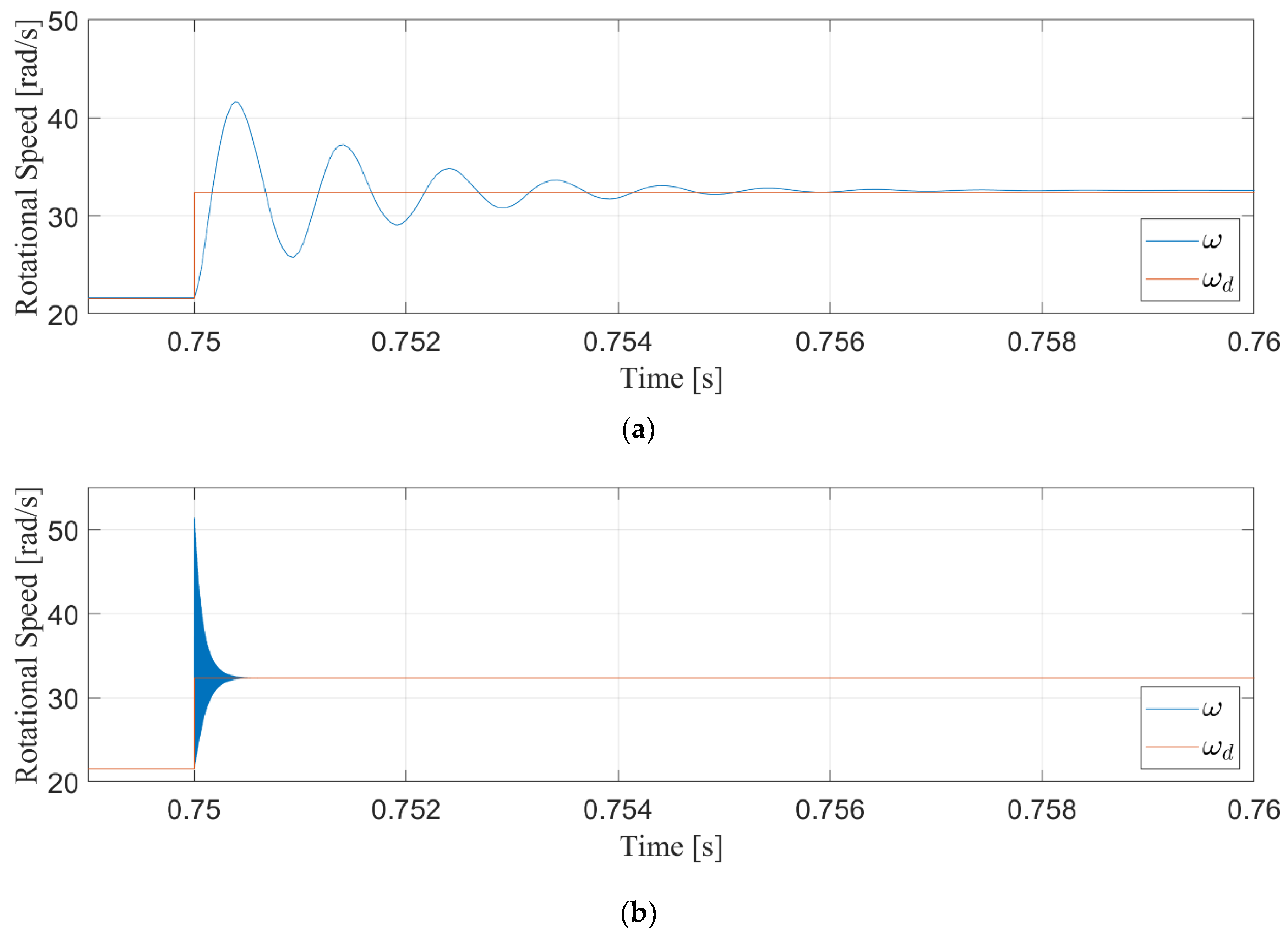
The first experimental trial performed to compare these two controllers was a wind speed step. While an instantaneous rise in wind speed is not possible in these applications, sharp changes in wind happen regularly, and this experiment simulates a worst-case scenario. For the purposes of this test, a wind speed step occurred at t = 0.75 from 8 m/s to 12 m/s. As discussed in Remark 1, this will influence the desired speed trajectory ω d based on (5).
The response of both controllers is shown in Figure 3. It is clear from the difference in time scales that the nonlinear controller responds much faster to changes in wind speeds as compared to the linear controller. For a numerical comparison, the settling time for each controller is presented in Table 4.
These results show that the nonlinear controller is roughly 10 times faster than the linear controller. This increased responsiveness allows for higher precision control in the face of rapidly changing wind speeds, as illustrated by the next experiment.

4.5. Turbulent Wind Results

The second experiment used to compare these controllers was the input of a more realistic turbulent wind speed. The turbulent wind speed used during this experiment is presented in Figure 4. This corresponds to a torque T L based on (2) where C p is calculated from equations found in [28].
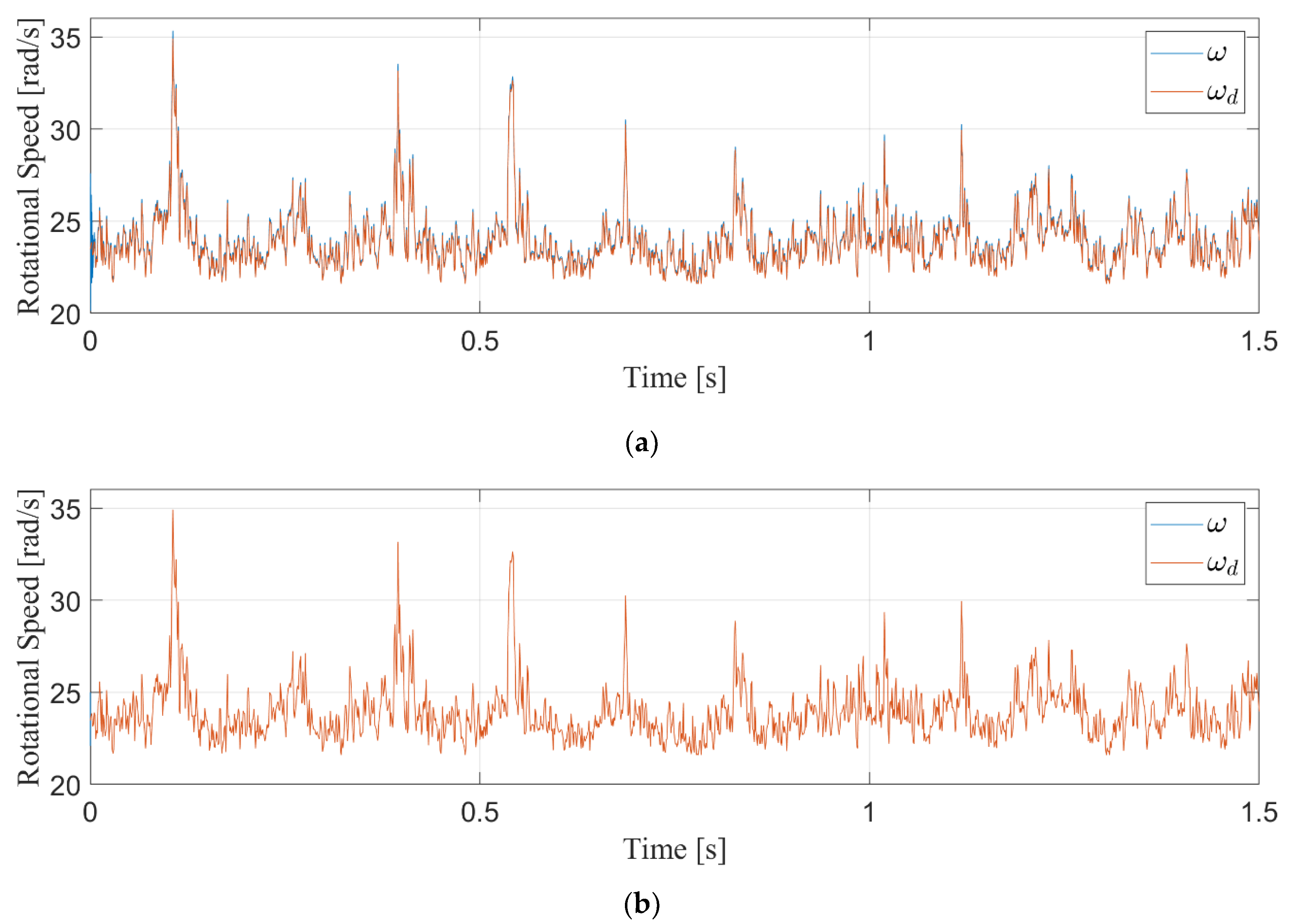
As discussed in Remark 1, the desired speed trajectory ω d was designed based on (5), as seen in Figure 5.
The speed tracking results for both controllers are shown in Figure 6. This illustrates that while both controllers are able to track the desired speed trajectory, the proposed controller is far more accurate.
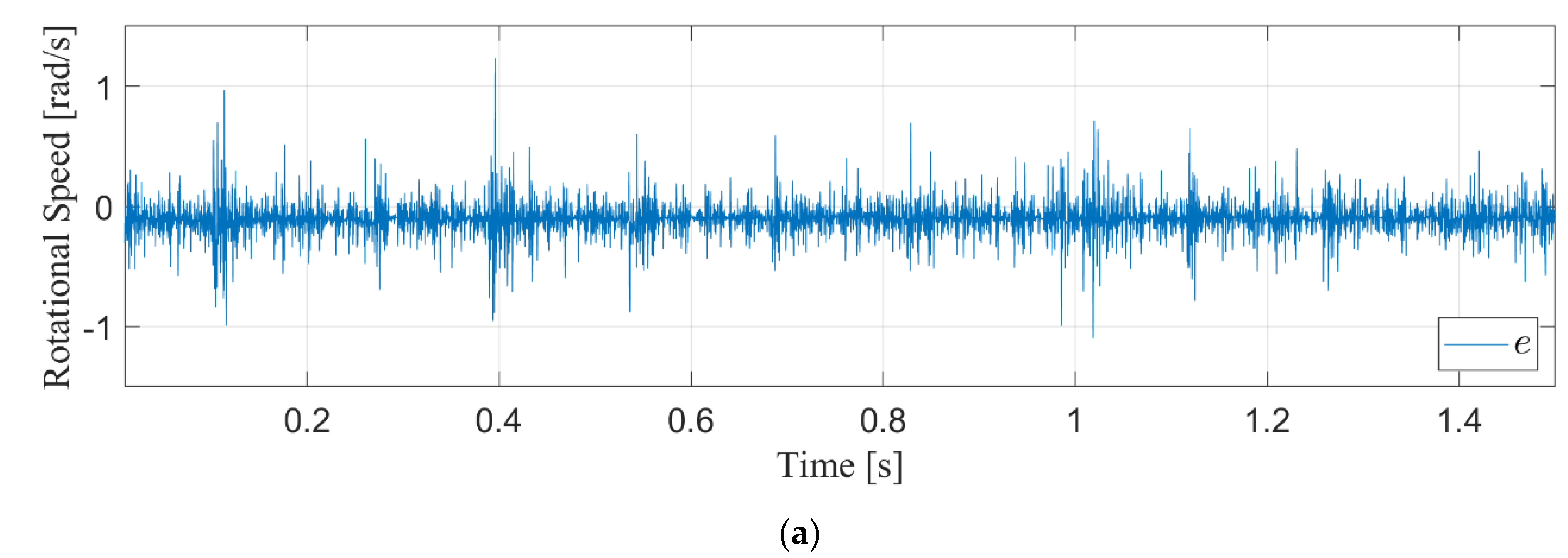
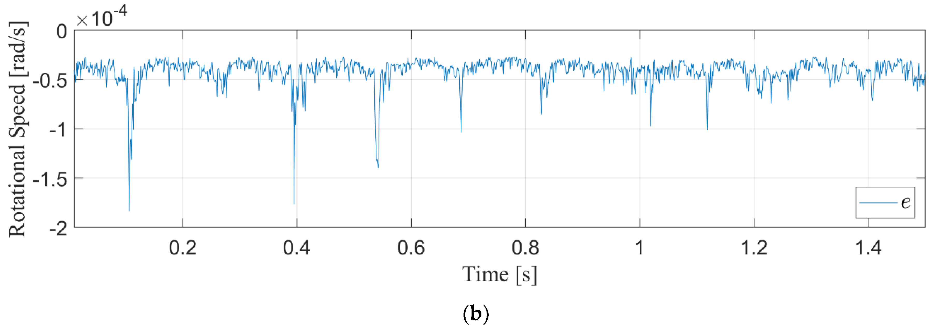
These results can be further examined through the speed errors, e , which are shown in Figure 7. These results can be numerically compared by looking at the RMS errors throughout the operation of the wind turbine, as shown in Table 5. It can be seen from the data presented below that the proposed controller manages the rapidly changing wind speeds much better than a traditional controller. Based on Table 5, the nonlinear controller achieves over 30 times more accurate speed management.
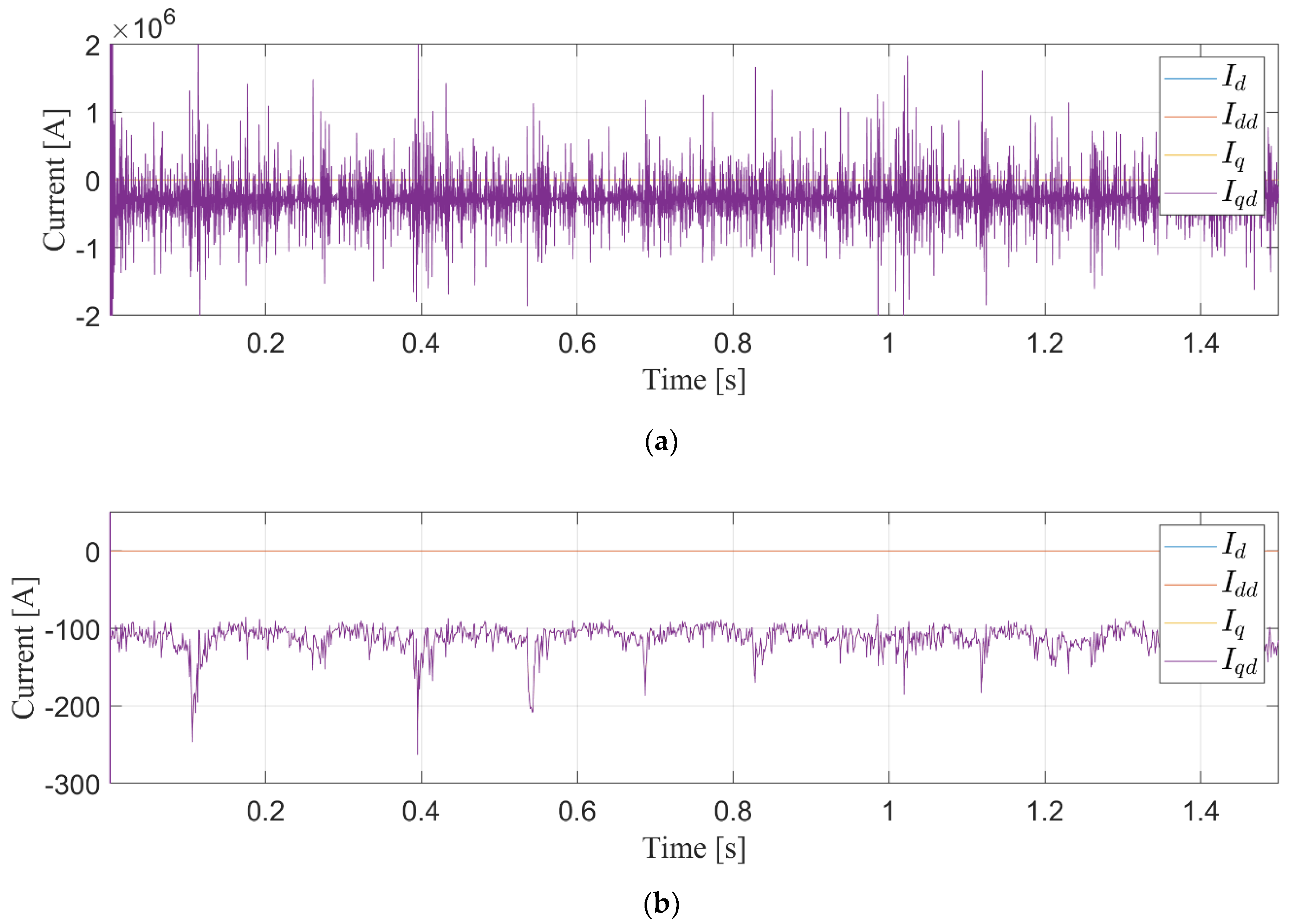
Beyond the primary control objective of speed management is the intermediate current objective. The currents for each controller alongside their desired values are shown in Figure 8. It is clear from this that the linear controller, in an effort to manage the speed, struggles to stay in the generating mode (i.e., negative current). The proposed controller is far more consistent in this regard, staying in the generating mode throughout the turbulent winds.
Finally, it is important that these controls are achieved in a realistic fashion. This is determined by the control signals themselves, which are the PMSG terminal voltages. Figure 9 shows the voltages for both controllers and it is apparent that both are certainly able to be produced by a typical 3-phase power converter.

5. Conclusions

A nonlinear controller is proposed to increase the operational mechanical efficiency of a PMSG wind turbine through high precision rotational speed control. Results show that, as compared to a traditional vector control scheme, the proposed controller achieves significantly higher fidelity control in the presence of turbulent wind speeds. Results show that the proposed control scheme is 10 times faster and 30 times more accurate than a traditional linear controller. This increase in precision improves the overall performance of these wind turbine systems.
The proposed controller comes with many advantages besides this superior performance. PMSGs are more efficient and have a better speed range than other WECS topologies, and the use of a Type 4 circuit leads to 100% power controllability. This controller accurately manages the generator speed with no knowledge of the wind speed and is widely implementable in most any wind generator setting that utilizes this machine type. This strength is in part due to the linear scheme’s dependency on cascaded PI architecture, which requires at least six gains to be well-tuned for sufficient performance, compared to the proposed scheme only needing four.
One weakness of the proposed controller is the need for parameter knowledge, though future work will address this to some extent. There are also some weaknesses that typically appear in the implementation process, which include switching nonlinearities and grid synchronization. However, these issues will affect both the proposed controller and the compared linear scheme.

Author Contributions

Conceptualization, N.H. and M.L.M.; methodology, N.H. and M.L.M.; software, N.H.; validation, N.H. and M.L.M.; formal analysis, N.H. and M.L.M.; investigation, N.H.; resources, M.L.M.; data curation, N.H.; writing—original draft preparation, N.H.; writing—review and editing, M.L.M.; visualization, N.H.; supervision, M.L.M.; project administration, M.L.M.; funding acquisition, M.L.M. All authors have read and agreed to the published version of the manuscript.

Funding

This research received no external funding.

Institutional Review Board Statement

Not applicable.

Informed Consent Statement

Not applicable.

Data Availability Statement

Data sharing is not applicable.

Conflicts of Interest

The authors declare no conflict of interest.

References

  1. Chen, Z.; Guerrero, J.M.; Blaabjerg, F. A review of the state of the art of power electronics for wind turbines. IEEE Trans. Power Electron. 2009, 24, 1859–1875. [Google Scholar] [CrossRef]
  2. Yaramasu, V.; Wu, B.; Sen, P.C.; Kouro, S.; Narimani, M. High-power wind energy conversion systems: State-of-the-art and emerging technologies. Proc. IEEE 2015, 103, 740–788. [Google Scholar] [CrossRef]
  3. IRENA. Wind Energy. 2018. Available online: https://irena.org/wind (accessed on 17 November 2019).
  4. U. E. I. Administration. Table 10.1 Renewable Energy Production and Consumption by Source; US Department of Energy: Washington, DC, USA, 2018.
  5. U.S. Department of Energy. Wind Vision: A New Era for Wind Power in the United States; US Department of Energy: Washington, DC, USA, 2015.
  6. Fateh, F.; White, W.N.; Gruenbacher, D. A Maximum Power Tracking Technique for Grid-Connected DFIG-Based Wind Turbines. IEEE J. Emerg. Sel. Top. Power Electron. 2015, 3, 957–966. [Google Scholar] [CrossRef]
  7. Haque, M.E.; Negnevitsky, M.; Muttaqi, K.M. A Novel Control Strategy for a Variable-Speed Wind Turbine with a Permanent-Magnet Synchronous Generator. IEEE Trans. Ind. Appl. 2010, 46, 331–339. [Google Scholar] [CrossRef] [Green Version]
  8. Goudarzi, N.; Zhu, W.D. A review on the development of wind turbine generators across the world. Int. J. Dyn. Control 2013, 1, 192–202. [Google Scholar] [CrossRef] [Green Version]
  9. Han, K.; Chen, G.-Z. A novel control strategy of wind turbine MPPT implementation for direct-drive PMSG wind generation imitation platform. In Proceedings of the IEEE 6th International Power Electronics and Motion Control Conference, Wuhan, China, 17–20 May 2009. [Google Scholar]
  10. Uehara, A.; Pratap, A.; Goya, T.; Senjyu, T.; Yona, A.; Urasaki, N.; Funabashi, T. A Coordinated Control Method to Smooth Wind Power Fluctuations of a PMSG-Based WECS. IEEE Trans. Energy Convers. 2011, 26, 550–558. [Google Scholar] [CrossRef]
  11. Torki, W.; Grouz, F.; Sbita, L. Vector control of a PMSG direct-drive wind turbine. In Proceedings of the 2017 International Conference on Green Energy Conversion Systems (GECS), Hammamet, Tunisia, 23–25 March 2017. [Google Scholar]
  12. Sahu, S.; Panda, G.; Yadav, S.P. Dynamic Modelling and Control of PMSG based Stand-alone Wind Energy Conversion System. In Proceedings of the 2018 Recent Advances on Engineering, Technology and Computational Sciences (RAETCS), Allahabad, India, 6–8 February 2018. [Google Scholar]
  13. Wen, C.; Lu, G.; Wang, P.; Li, Z.; Liu, X.; Fan, Z. Vector control strategy for small-scale grid-connected PMSG wind turbine converter. In Proceedings of the 2011 2nd IEEE PES International Conference and Exhibition on Innovative Smart Grid Technologies, Manchester, UK, 5–7 December 2011. [Google Scholar]
  14. Errami, Y.; Maaroufi, M.; Ouassaid, M. Modelling and control strategy of PMSG based variable speed wind energy conversion system. In Proceedings of the 2011 International Conference on Multimedia Computing and Systems, Ouarzazate, Morocco, 7–9 April 2011. [Google Scholar]
  15. Davoodnezhad, R.; Holmes, D.G.; McGrath, B.P.; Vahidnia, A. Self-synchronising stator terminal control of permanent magnet synchronous generators for wind energy conversion systems. In Proceedings of the IEEE 7th International Symposium on Power Electronics for Distributed Generation Systems (PEDG), Vancouver, BC, Canada, 7–30 June 2016. [Google Scholar]
  16. Boobalan, M.; Vijayalakshmi, S.; Brindha, R. A fuzzy-PI based power control of wind energy conversion system using PMSG. In Proceedings of the 2013 International Conference on Energy Efficient Technologies for Sustainability, Nagercoil, India, 10–12 April 2013. [Google Scholar]
  17. Rhaili, S.; Abbou, A.; Ziouh, A.; Elidrissi, R. Comparative study between PI and FUZZY logic controller in vector controlled five-phase PMSG based variable-speed wind turbine. In Proceedings of the 2018 IEEE 12th International Conference on Compatibility, Power Electronics and Power Engineering (CPE-POWERENG 2018), Doha, Qatar, 10–12 April 2018. [Google Scholar]
  18. Dixon, W.E.; Behal, A.; Dawson, D.M.; Nagarkatti, S.P. Nonlinear Control of Engineering Systems: A Lyapunov-Based Approach; Springer: New York, NY, USA, 2012. [Google Scholar]
  19. Djagarov, N.; Grozdev, Z.; Bonev, M.; Djagarova, J.; Pazderin, A.V.; Kokin, S. Adaptive control of wind PMSG. In Proceedings of the 2016 17th International Scientific Conference on Electric Power Engineering (EPE), Prague, Czech Republic, 16–18 May 2016. [Google Scholar]
  20. Kchaou, A.; Naamane, A.; Koubaa, Y.; M’Sirdi, N.K. Nonlinear control of a permanent magnet synchronous generator in wind energy conversion system with maximum power extraction. In Proceedings of the 18th International Conference on Sciences and Techniques of Automatic Control and Computer Engineering (STA), Monastir, Tunisia, 21–13 December 2017. [Google Scholar]
  21. Torki, W.; Grouz, F.; Sbita, L. A sliding mode model reference adaptive control of PMSG wind turbine. In Proceedings of the International Conference on Green Energy Conversion Systems (GECS), Hammamet, Tunisia, 23–25 March 2017. [Google Scholar]
  22. Lee, S.-W.; Chun, K.-H. Adaptive Sliding Mode Control for PMSG Wind Turbine Systems. Energies 2019, 12, 595. [Google Scholar] [CrossRef] [Green Version]
  23. Gajewski, P.; Pienkowski, K. Analysis of Sliding Mode Control of variable speed wind turbine system with PMSG. In Proceedings of the 2017 International Symposium on Electrical Machines (SME), Naleczow, Poland, 18–21 June 2017. [Google Scholar]
  24. Jena, N.K.; Mohanty, K.B.; Pradhan, H.; Sanyal, S.K. A comparison between PI & SMC used for decoupled control of PMSG in a variable speed wind energy system. In Proceedings of the 2015 International Conference on Energy, Power and Environment: Towards Sustainable Growth (ICEPE), Shillong, India, 12–13 June 2015. [Google Scholar]
  25. Kim, K.-H.; Jeung, Y.-C.; Lee, D.-C.; Kim, H.-G. Robust control of PMSG wind turbine systems with back-to-back PWM converters. In Proceedings of the 2nd International Symposium on Power Electronics for Distributed Generation Systems, Hefei, China, 16–18 June 2010. [Google Scholar]
  26. Ali, M.; Guo, F.; Gou, B.; Ali, M. Nonlinear control design using exact linearization for permanent magnet synchronous generator. In Proceedings of the IEEE International Conference on Electro-Information Technology, EIT 2013, Rapid City, SD, USA, 9–11 May 2013. [Google Scholar]
  27. Li, X.-C.; Zhao, Y.-N.; Zui-Bing, X. Nonlinear control of permanent magnet wind turbine generation (PSMG). In Proceedings of the 2013 International Conference on Power, Energy and Control (ICPEC), Sri Rangalatchum Dindigul, India, 6–8 February 2013. [Google Scholar]
  28. Abir, A.; Mehdi, D.; Lassaad, S. Pitch angle control of the variable speed wind turbine. In Proceedings of the 2016 17th International Conference on Sciences and Techniques of Automatic Control and Computer Engineering (STA), Sousse, Tunisia, 19–21 December 2016. [Google Scholar]
  29. Zhou, J.; Li, S.; Li, J.; Zhang, J. A combined control strategy of wind energy conversion system with direct-driven PMSG. In Proceedings of the 2016 31st Youth Academic Annual Conference of Chinese Association of Automation (YAC), Wuhan, China, 11–13 November 2016. [Google Scholar]
  30. Zhang, X.; Wang, K. Model predictive current control for the semi-controlled open winding PMSG. In Proceedings of the 2017 20th International Conference on Electrical Machines and Systems (ICEMS), Sydney, Australia, 11–14 August 2017. [Google Scholar]
  31. Chang, Y.-C.; Tsai, C.-T.; Lu, Y.-L. Current Control of the Permanent-Magnet Synchronous Generator Using Interval Type-2 T-S Fuzzy Systems. Energies 2019, 12, 2953. [Google Scholar] [CrossRef] [Green Version]
  32. Ma, Y.; Tao, L.; Zhou, X.; Li, W.; Shi, X. Analysis and Control of Wind Power Grid Integration Based on a Permanent Magnet Synchronous Generator Using a Fuzzy Logic System with Linear Extended State Observer. Energies 2019, 12, 2862. [Google Scholar] [CrossRef] [Green Version]
  33. Jisha, L.; Thomas, A.A.P. A comparative study on scalar and vector control of Induction motor drives. In Proceedings of the 2013 International conference on Circuits, Controls and Communications (CCUBE), Bengaluru, India, 27–28 December 2013. [Google Scholar]
  34. Horch, M.; Boumédiène, A.; Baghli, L. Backstepping approach for nonlinear super twisting sliding mode control of an induction motor. In Proceedings of the 2015 3rd International Conference on Control, Engineering & Information Technology (CEIT), Tlemcen, Algeria, 25–27 May 2015. [Google Scholar]
  35. Hawkins, N.; Alqatamin, M.; Bhagwat, B.; McIntyre, M.L. Nonlinear Control and Observation of a PMSG Wind Turbine through Unknown Wind Torque Characteristics. In Proceedings of the American Controls Conference, Denver, CO, USA, 1–3 July 2020. [Google Scholar]
  36. Li, M.; Smedley, K. One-cycle control of PMSG for wind power generation. In Proceedings of the IEEE Power Electronics and Machines in Wind Applications, Lincoln, NE, USA, 24–26 June 2009. [Google Scholar]
  37. Li, H.; Shi, K.; McLaren, P. Neural-network-based sensorless maximum wind energy capture with compensated power coefficient. IEEE Trans. Ind. Appl. 2005, 41, 1548–1556. [Google Scholar] [CrossRef]
  38. Fdaili, M.; Essadki, A.; Nadour, M.; Nasser, T. Comparative Study of MPPT and Pitch Angle Control Strategies for a Wind Energy Conversion System. In Proceedings of the 2017 International Renewable and Sustainable Energy Conference (IRSEC), Tangier, Morocco, 4–7 December 2017. [Google Scholar]
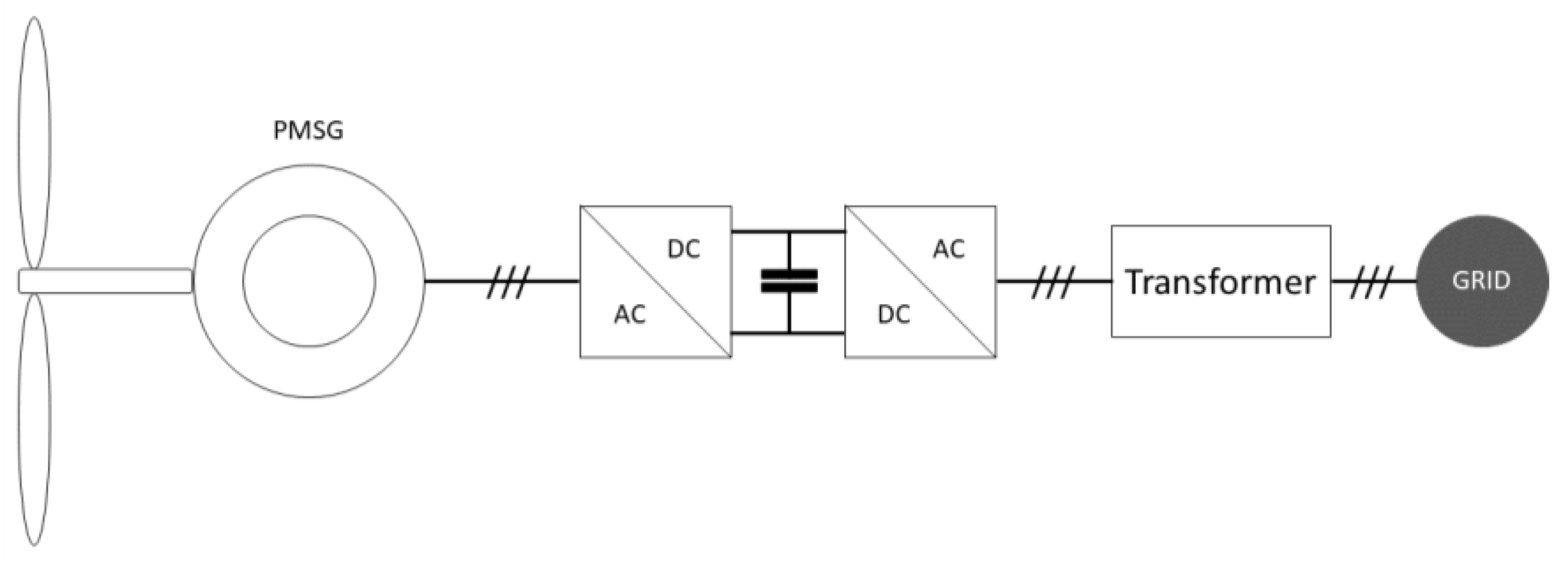
Figure 1. Type 4 Configuration for WECS with a PMSG.
Energies 14 00954 g001
Figure 2. Linear control architecture for PMSG.
Energies 14 00954 g002
Figure 3. Step response of linear controller (a) and nonlinear controller (b) from change in wind speed.
Energies 14 00954 g003
Figure 4. Turbulent wind speed profile for controller comparison.
Energies 14 00954 g004
Figure 5. Desired speed trajectory for controller comparison.
Energies 14 00954 g005
Figure 6. Rotational speed versus desired trajectory for linear controller (a) and nonlinear controller (b).
Energies 14 00954 g006
Figure 7. Rotational speed error for linear controller (a) and nonlinear controller (b).
Energies 14 00954 g007aEnergies 14 00954 g007b
Figure 8. PMSG currents and references for linear controller (a) and nonlinear controller (b).
Energies 14 00954 g008
Figure 9. PMSG voltages for linear controller (a) and nonlinear controller (b).
Energies 14 00954 g009
Table 1. System parameters for simulation platform.
ParameterValueUnits
J 0.0078 kg · m 2
B 0 kg · m 2 / s
p 8# poles
λ m 0.36 V · s
R s 0.42
L s 6.9mH
ρ 1.225 kg / m 3
R 3m
λ d 8.0977-
Table 2. Control gains for nonlinear controller.
ParameterValue
k 100
k q 50
k d 5
ε 1
Table 3. Control gains for linear controller.
ParameterValue
k d P 10,000
k d I 0.01
k ω P 1000
k ω I 100
k q P 1
k q I 500
Table 4. Settling time of linear and nonlinear controllers after wind step change.
ControllerSettling Time (s)
Linear0.006
Nonlinear0.0006
Table 5. RMS speed control errors for linear and nonlinear controllers.
ControllerRMS Error (rad/s)
Linear0.185994
Nonlinear0.005751
Publisher’s Note: MDPI stays neutral with regard to jurisdictional claims in published maps and institutional affiliations.