Article

Thermal Analysis of Organic and Nanoencapsulated Electrospun Phase Change Materials

1
Department of the Built Environment, Division of Sustainability, Energy and Indoor Environment, Aalborg University, 2450 København SV, Denmark
2
Department of Materials and Production, Aalborg University, 9220 Aalborg Ø, Denmark
*
Author to whom correspondence should be addressed.
Energies 2021, 14(4), 995; https://doi.org/10.3390/en14040995
Submission received: 7 January 2021 / Revised: 7 February 2021 / Accepted: 10 February 2021 / Published: 14 February 2021
(This article belongs to the Special Issue Thermal Energy Storage in Building Integrated Thermal Systems)

Abstract

:
Latent heat stored in phase change materials (PCM) can greatly improve energy efficiency in indoor heating/cooling applications. This study presents the materials and methods for the formation and characterization of a PCM layer for a latent heat thermal energy storage (LHTES) application. Four commercially available PCMs comprising the classes of organic paraffins and organic non-paraffins were selected for thermal storage application. Pure organic PCM and PCM in water emulsions were experimentally investigated. PCM electrospun microfibers were produced by a co-axial electrospinning technique, where solutions of Polycaprolactone (PCL) 9% w/v and 12% w/v in dichloromethane (DCM) were used as the fiber shell materials. PCM emulsified with sodium dodecyl sulfate (SDS), and Polyvinylalcohol 10% w/v (PVA) constituted the core of the fibers. The thermal behavior of the PCM, PCM emulsions, and PCM electrospun fibers were analyzed with differential scanning calorimetry (DSC). A commercial organic paraffin with a phase change temperature of 18 °C (RT 18) in its pure and emulsified forms was found to be a suitable PCM candidate for LHTES. The PVA-PCM electrospun fiber matrix of the organic paraffin RT18 with a PCL concentration of 12% w/v showed the most promising results leading to an encapsulation efficiency of 67%.

1. Introduction

The growing energy crisis during the 1970s has led to an increased interest in renewable energy storage technologies. The latent heat storage materials (PCM) are used in various applications such as building applications [1], optical nanophotonic devices [2], phase change memory cells [3], spacecraft design, energy-absorbing clothing, food industry, and pharmaceutical applications [4]. LHTES with PCM is a technology implemented for indoor cooling applications to achieve a reduction in energy use and provide a satisfactory thermal comfort level. Sensible heat and latent heat constitute the total heat stored in a PCM. Sensible heat is related to the initial change in temperature, and latent heat is the heat stored throughout the phase change.
According to their initial and final phase, the PCMs are found in four categories: solid-solid, liquid-gas, solid-gas, and solid-liquid [5]. Solid-liquid PCMs [6] are particularly attractive as their significant heat storage capacity is accompanied by a small volume change (<10%) [7], and the temperature variation throughout each phase is small. A PCM remains in solid form until it absorbs a sufficient amount of heat to reach the melting point and becomes liquid. A reverse process occurs when a PCM in the liquid state is exposed to a temperature lower than the melting temperature.
Barrett K Green was the first researcher who attempted PCM encapsulation in the 1940s and 1950s [8]. Encapsulation facilitates the maintenance of shape in solid-liquid PCM, and at the same time, prevents the PCM from reacting with the surrounding fluids. The PCM encapsulation can help overcome phase segregation, low thermal conductivity, and volume expansions [9]. Electrospinning or electro-hydrodynamic processing is a low-cost method for the fabrication of ultrafine fibers in the range of micrometers to nanometers by drawing them from a liquid droplet of a polymeric solution or melt using high voltage [9]. The strong electric field produces charged threads of fibers. The significant parameters in the electrospinning process are the flow rate of the feeding solutions, the applied voltage, the collector distance, the capillary tube diameters, the viscosity, and the conductivity emitter of the feeding solutions [4]. Polymers are supporting materials for the encapsulation of the PCM through electrospinning. Numerous studies [5,6,7,10] demonstrate that the PCM incorporation in polymer matrices is an effective conjugate electrospinning method. An emulsion electrospinning technique was employed by Chalco-Sandoval et al. [11], and the proposed method is investigated in the current study.
The objective of the current work is the experimental evaluation of the thermal properties of commercially available PCMs and their potential use as novel electrospun energy storage materials, able to enhance the thermal storage capacity of LHTES systems [12]. PCMs with a phase change temperature range of 15 to 20 °C are suitable for moderate climate locations, e.g., Denmark, and are explored in the present study.

2. Materials and Methods

2.1. Phase Change Materials

Chemical and physical stability of organic PCMs makes them suitable for LHTES applications. Commercial PCMs for application in the temperature range 15–20 °C have been recently reviewed [13]. In the current study, four commercially available materials and their mixtures are investigated. The examined PCMs belong to the classes of organic paraffins and non-paraffins. Organic paraffins are widely used in LHTES applications at room temperature due to their high latent heat capacity, chemical and physical stability, reliability, and low cost [6]. However, organic paraffins are petroleum-based and not environmentally friendly. On the contrary, organic non-paraffinic PCMs are bio-based and have been recently evaluated for thermal energy storage (TES) applications. Technical grade paraffins RT15 and RT18, Rubitherm Technologies GmbH [14] and organic non-paraffins PT15 and PT18, Pure Temp LLC [15] with phase change temperatures of 15 and 18 °C, as indicated by the names, were selected for this study. RT 15 and RT18 are non-toxic, easy to handle technical grade paraffins that possess high latent heat capacity at constant temperatures [14]. Biodegradable organic non-paraffins PT15 and PT18 are produced by natural sources without the addition of chemical substances [15]. Table 1 shows the thermal properties of the four PCMs as provided by the manufacturers. The four organic PCMs were experimentally studied in their pure form, in water emulsions, and encapsulated in electrospun fiber matrices.
Furthermore, the long-term performance of the pure materials was evaluated by Differential Scanning Calorimetry (DSC) during 200 thermal cycles, which is equivalent to six months of real-time usage. The thermal performance of pure PCM for both 50, 100, 150, and 200 thermal cycles was evaluated with DSC. In their emulsion form, the organic PCM were mixed with water in ratios between 1:1 and 5:1. Two emulsifiers: Polyethylene glycol sorbitan (Tween 20) and Polyoxyethylensorbitan oleate (Tween 80), were added to a PCM-water mixture as stabilizers of PCM-in-water emulsions. The formation of PCM-in-water emulsions were observed, and no phase separation was detected. The emulsion images were analyzed with ImageJ software [16].

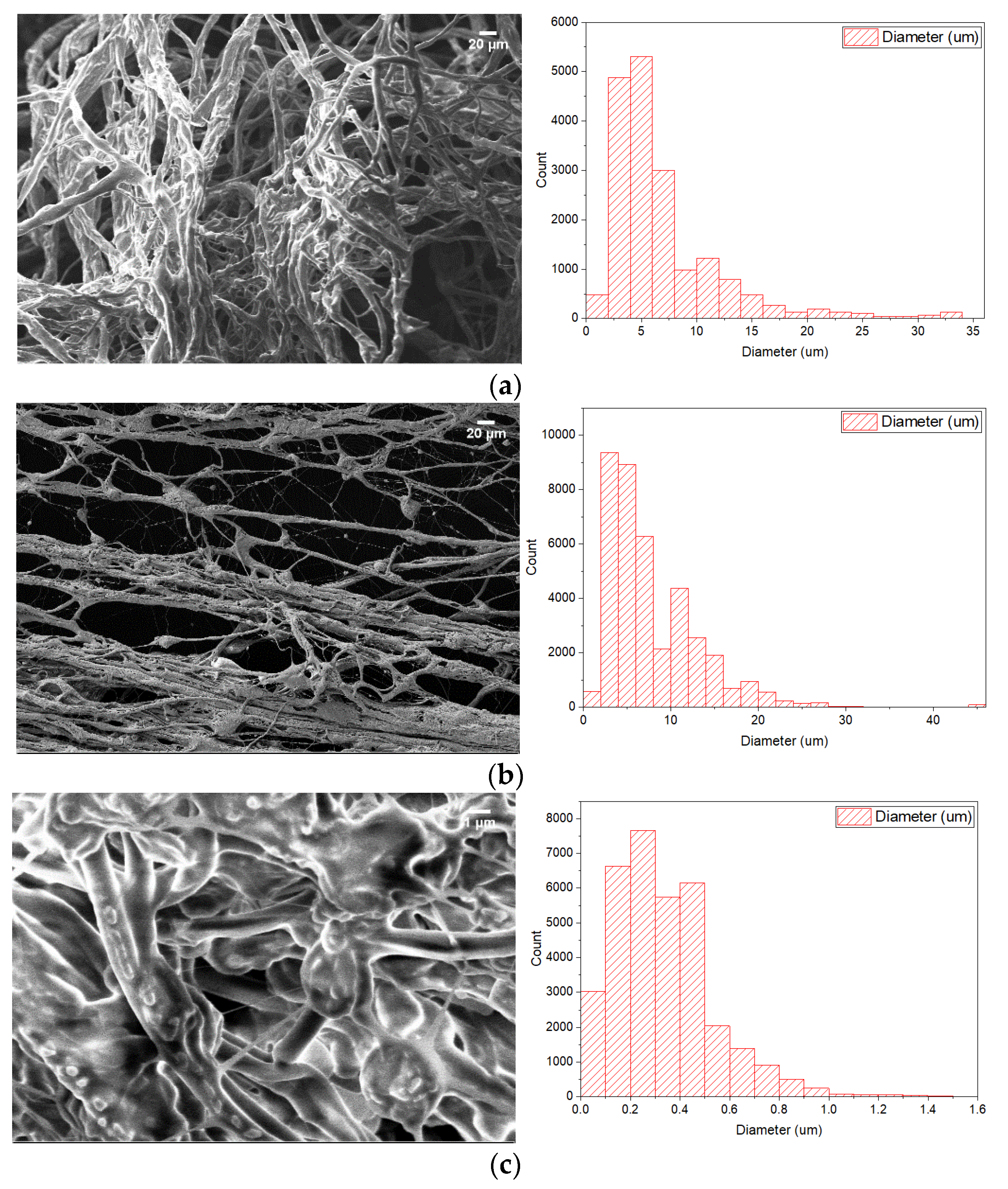
2.2. PCM Electrospun Fiber Matrix

According to the literature, the most common encapsulation techniques are spherical encapsulation and encapsulation in fiber matrices [17,18,19]. The innovative encapsulation of PCM in the core of electrospun fibers is achieved through co-axial electrospinning. In co-axial electrospinning or two-fluid electrospinning, two different materials are electrospun simultaneously to form core-shell fibers. The co-axial electrospinning setup consists of two capillary tubes, two syringes connected to the tubes, an inner and an outer needle for the core and shell materials, respectively, a grounded collector, and a high voltage source, as shown n Figure 1. The electrostatic field forces convert the droplets of the feeding materials into charged threads of fibers. The electrospun PCM fiber matrix is an efficient encapsulation technique since no further encapsulation is needed. The high surface to volume ratio of the electrospun PCM fiber leads to an increase in the thermal conductivity.
Organic paraffins can be efficiently encapsulated using co-axial electrospinning with a solution of polycaprolactone (PCL) [10] in a hydrophobic solvent. Two different solutions with the concentration of PCL in dichloromethane (DCM) of 9% w/v and 12% w/v were used for the fiber shell. The fiber core contained a PCM-PVA emulsion. PVA is a water-soluble, non-toxic polymer extensively used in electrospinning applications. The PVA emulsion was prepared by dissolving 10% w/v of PVA in distilled water and heating up to 100 °C with continuous stirring until fully dissolved [20]. An 80% v/v PCM emulsion in water was prepared with 8.4 mmol/L SDS added as a surfactant. The resulting PCM emulsion was homogenized with a T25 digital ULTRA-TURRAX disperser and then mixed with the PVA emulsion in a 1:1 ratio. A non-ionic surfactant Triton X at 0.07% was added to improve the emulsion’s spinnability. The core and shell solutions were filled into two plastic 10 mL syringes connected to the capillary tubes.
The obtained PCM emulsion was co-axially electrospun with 9% w/v and 12% w/v PCL solutions using the setup described above. The voltage threshold for the electrospinning process varied between 10 to 15 kV. Voltages below 10 kV were not sufficient to overcome the surface tension to form a stable Taylor cone. Conversely, voltages higher than 15 kV led to larger fiber diameters, and the PCM was not properly encapsulated. The distance between the needle and the grounded collector plate was 18 cm. The inner diameter of the outer needle was 20 G, and the diameter of the inner needle was 10 G. Three different combinations of shell solution concentrations (% w/v) and flow rates of core and shell solutions were studied, as shown in Table 2.
The encapsulation ratio and the encapsulation efficiencies were calculated for the electrospun fiber matrices according to Equations (1) and (2), [21].
n = L m , encap , PCM L m , PCM , n = encapsulation ratio
ε = L m , encap , PCM + L s , encap , PCM L m , PCM + L s , PCM , ε = encapsulation efficiency
Thermal properties and morphology of the produced electrospun fiber matrices were characterized with Differential scanning calorimetry (DSC Q2000, TA Instruments, New Castle, DE, USA), scanning electron (Zeiss XB1540), and optical microscopy (Zeiss Axioskop 2 Plus). The images were processed with ImageJ software [16].

3. Results

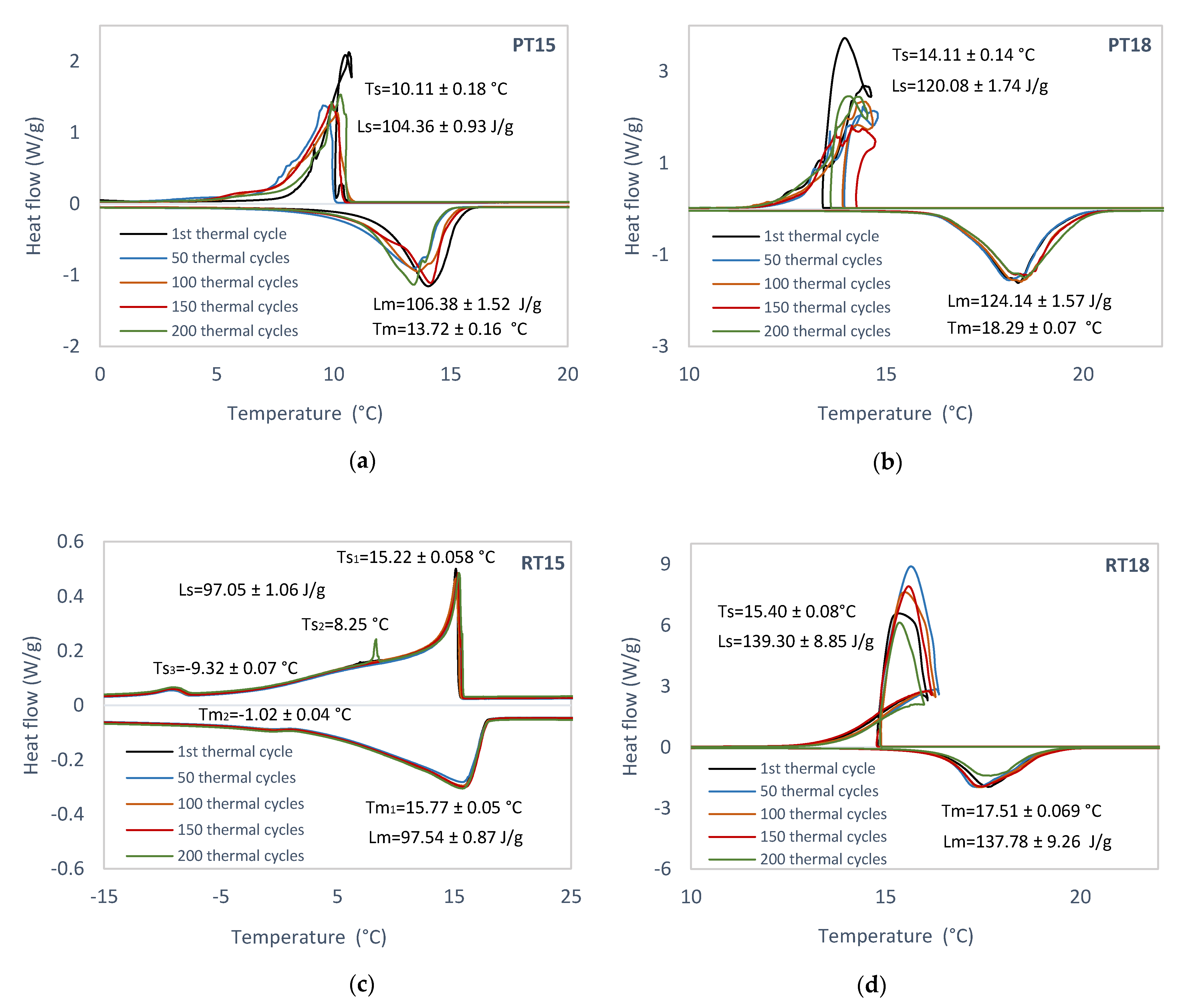
3.1. Experimental Identification of Pure PCM

The long-term performance of technical grade paraffinic and non-paraffinic PCMs was evaluated with 50, 100, 150 and 200 thermal cycles [22]. The samples were manually cycled for up to 200 cycles in a temperature range of −30 to +80 °C with a scanning rate of 1.5 °C/min in a dynamic mode. The mass of each sample was ca. 6 mg. Figure 2 shows the obtained melting/solidification temperatures and enthalpies.

3.2. Experimental Characterization of PCM Emulsions

Stable oil in water emulsions with 1:1 to 5:1 ratios were formed with Tween 20 and Tween 80 as emulsifiers. The emulsions were formed with an Ultraturrax at 16,000 rpm. The mass of the samples varied between 4 to 8 mg. The expanded uncertainty for each experimental measurement was ±0.1%. Figure 3 illustrates the DSC thermograms of the two organic non-paraffins and the two organic paraffins prepared as water emulsions. Moreover, the optical microscopy images and the average emulsion sizes of the four PCM-in-water emulsions are presented in Figure 4 and Table 3, respectively.

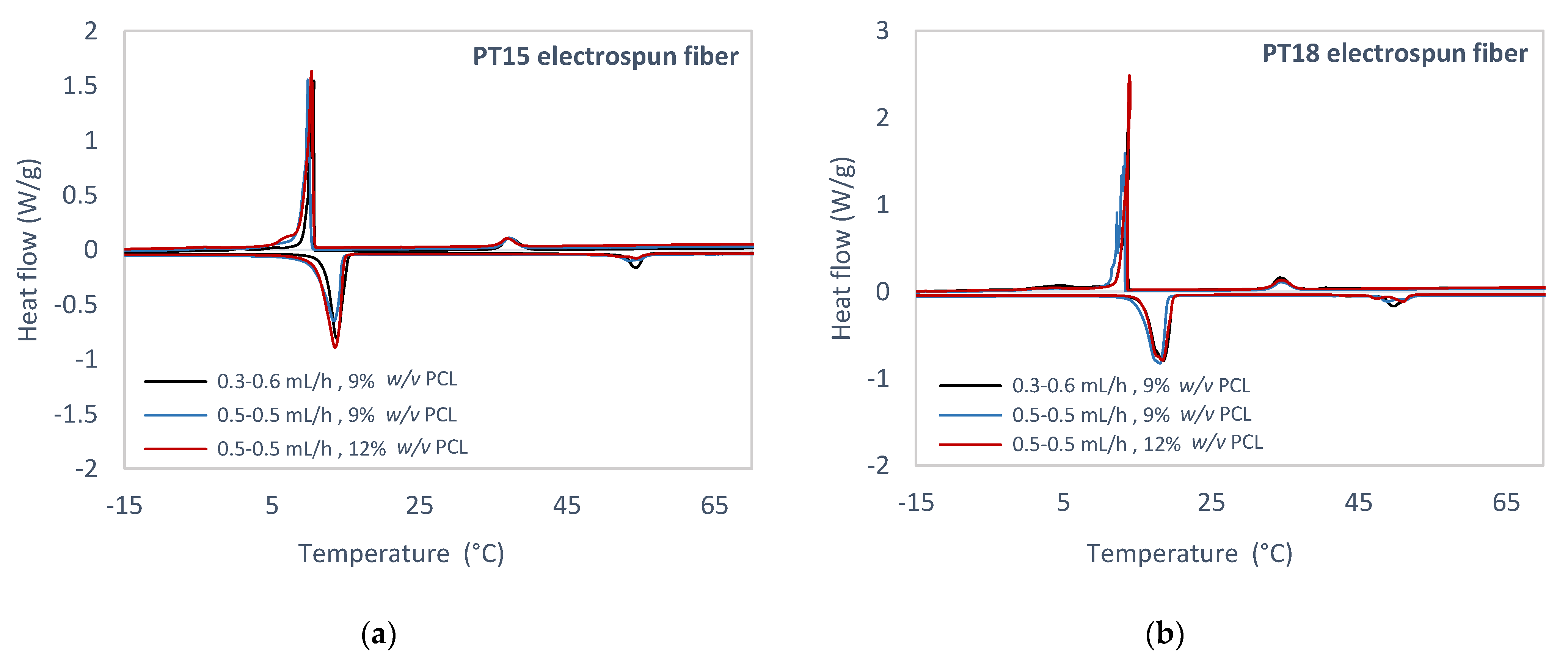
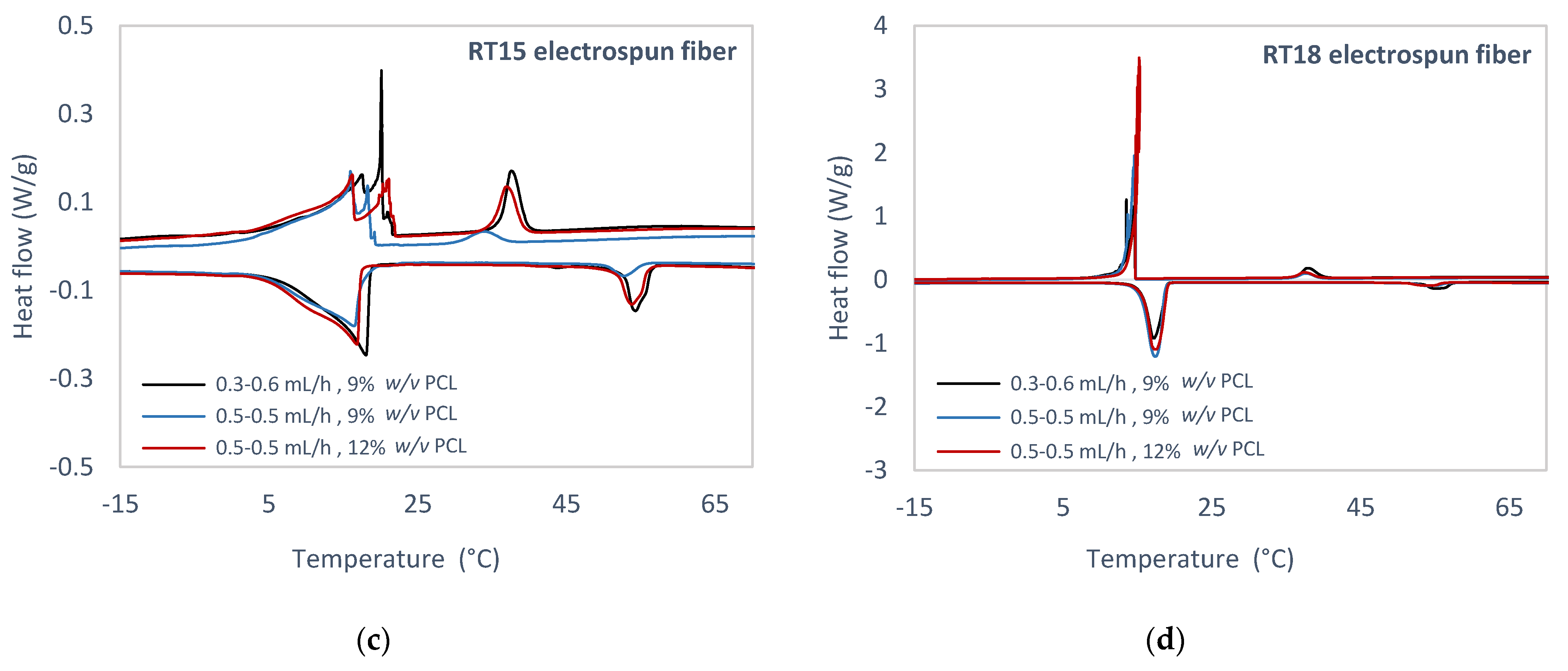
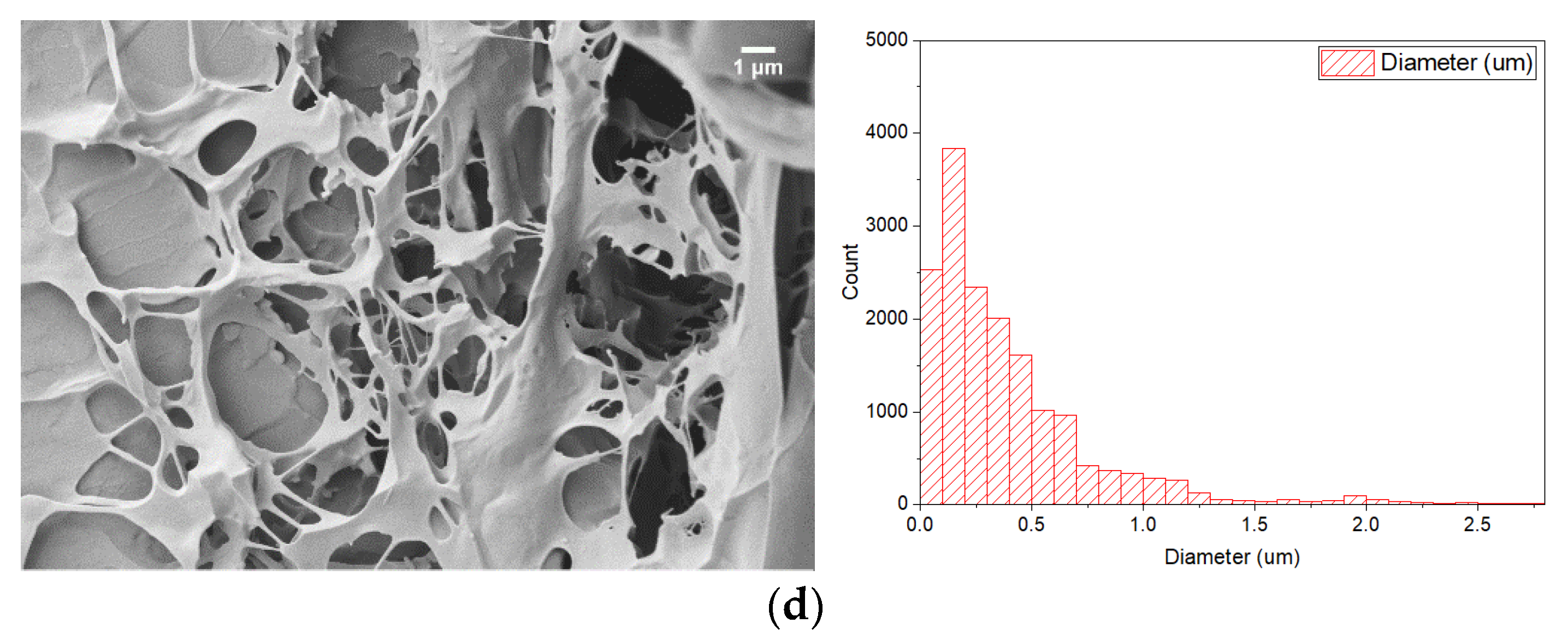
3.3. Experimental Study of PCM Electrospun Fiber Matrix

Four PCMs selected for the study were encapsulated as PVA emulsions forming the core of the PCM electrospun fiber matrix, which was encapsulated in a PCL shell. The samples of the electrospun PCM fibers were tested in the temperature range of −30 to 80 °C with a scanning rate of 1.5 °C/min in dynamic mode. The mass of each sample was about 3 mg. The expanded uncertainty for each experimental measurement was ±0.1%. Figure 5 and Table 4 show the DSC thermographs and analysis results for electrospun PCM fibers of PT15, PT18, RT15, and RT18 in the 1st thermal cycle. Figure 6, Figure 7 and Figure 8 depict the morphology of the PCM electrospun fiber matrices. The fiber shell was formed with either 9% w/v or 12% w/v PCL. The encapsulation ratio n is shown in Table 5.

4. Discussion

4.1. Experimental Identification of Pure PCM

Several studies [23,24,25,26,27] have addressed the long term stability of PCM over an extended duty cycle in real-life applications. Behzadi and Farid [23] examined commercial organic PCMs and observed a shift in the melting point from 21 to 28 °C and an increase of 36 J/g in the latent heat of fusion over thermal cycles representing 120 days. Sharma et al. [24] concluded that all of the examined organic PCM exhibited a decrease in the melting temperature after being subjected to 500 thermal cycles. Rathod and Banerjee [25] reviewed the thermal stability of PCM in LHTES applications and observed stable performance of organic paraffins under repeated thermal cycles. A. Shukla et al. [26] investigated paraffin waxes, which demonstrated stable thermal performance over 1000 thermal cycles. Hasan and Sayigh [27] examined industrial-grade organic non-paraffins and observed a 10% reduction in the heat of fusion after 450 thermal cycles.
In the current study, the scanning rate of 1.5 °C/min ensures a high resolution of the melting and freezing peaks. The melting/solidification point results acquired from the DSC analysis are highly dependent on the scanning rate and sample preparation laboratory methods. The scanning rate significantly affects the peak thermal shifts in the heating and cooling curves. Table 1 reports that the experimental latent heats in all examined cases were lower than the latent heats provided by the manufacturers. The difference between melting and solidification point arises due to the effect of sub-cooling or incongruent melting. In all cases, except for RT15, a thermal shift between the melting and solidification curve is observed. The thermal shift reaches 3.5 °C for PT15, 4.5 °C for PT18, and 2.5 °C for RT18. The DSC data in Figure 2 indicate a nearly constant latent heat (J/g) and excellent thermal stability and reliability during the thermal cycle tests for the examined materials. No significant changes were observed in the melting and crystallization temperature and enthalpies between 0 and 200 thermal cycles. The stable thermal performance of the examined PCMs is in line with the literature [23,24,25,26,27]. The standard error of mean analysis (Figure 2) demonstrates that the average values for the melting/solidification points and melting/solidification latent heats are in all the examined cases highly reproducible. However, it has been reported that the solidification and melting enthalpy of RT18 for the 200 thermal cycles have been decreased by 33% in comparison with the 50,100 and 150 thermal cycles [22]. The obtained melting and freezing points are 13.72 ± 0.16 °C and 10.11 ± 0.18 °C for the organic non-paraffin PT15 (Figure 2a) and 18.29 ± 0.07 °C and 14.11 ± 0.14 °C for the organic non-paraffin PT18 (Figure 2b). The organic paraffin RT15 exhibits melting and solidification peaks lower than 15 °C (Figure 2c). The average melting and solidification points for RT18 are 17.51 ± 0.069 °C and 15.40 ± 0.08 °C (Figure 2d). Correspondingly the average latent heats of melting and solidification of RT18 are 137.78 ± 9.26 J/g and 139.30 ± 8.85 J/g. According to this analysis, since RT18 in all data sets for 50, 100, 150, and 200 thermal cycles performed stably in terms of melting/freezing temperature (°C) and enthalpies (J/g), it can be considered as a suitable PCM candidate for thermal energy storage applications in moderate climate conditions.

4.2. Experimental Identification of PCM Emulsions

PCM in water emulsions are novel heat transfer fluids characterized as thermodynamically unstable systems [28]. Zhang et al. [29] developed a water-PCM emulsion, and they concluded that the degree of supercooling increases with a decrease in the droplet size of the emulsion. The result exhibited no phase separation in the oil in water emulsions with Tween 80 as emulsifier.
The emulsions of PCM in water at different ratios were produced and analyzed using the DSC technique to identify and quantify whether the heat capacity of the final solution displays an increase or not. The experimentally found melting and solidification points of the emulsions of PT15 (Figure 3a) and PT18 (Figure 3b) were not in the temperature range 15–20 °C. In all cases, except for the RT15 emulsion (Figure 3c), a thermal hysteresis between the melting and solidification curves was observed. The hysteresis was 3 °C for PT15, 4 °C for PT18, and 2 °C for RT18. According to this analysis, RT18-in-water emulsion exhibited melting and solidification temperatures in the range of 15–20 °C and high melting and solidification enthalpies of ca. 180 J/g.
The PCM emulsion images were captured a few hours after sample preparation. Günther et al. [30] studied n-hexadecane emulsions with a size range of 0.1–20 μm. The average emulsion size given in Table 3 varied between 5 to 11 μm. The average emulsion sizes (Table 3) are over 1 μm, which characterizes them as thermodynamically unstable macro-emulsion systems. In all examined PCM emulsions, the emulsification process was conducted with the same percentage of PCM, water, emulsifier in the solution and the same energy input.

4.3. Experimental Study of PCM Electrospun Fiber Matrix

Several studies [5,6] have demonstrated successful PCM incorporation in polymer matrices by electrospinning. Perez-Masia et al. [10] encapsulated the organic paraffin dodecane in PCL through single fluid electrospinning. The results indicated that the electrospun fiber with encapsulated PCM maintained about 37% of the bulk PCM heat storage capacity. Chalco-Sandoval et al. [11] achieved an encapsulation of PCM/PVA in a PCL shell using co-axial electrospinning. The electrospun fiber matrices were formed using an electrospinning setup, and their thermal properties were analyzed with DSC and SEM.
The DSC thermographs of PT15 (Figure 5a), PT18 (Figure 5b), and RT18 (Figure 5d) fiber matrices displayed two main well-defined peaks at the PCM phase change temperature and the shell material phase change temperature. In connection with RT15 (Figure 5c), two peaks for the PCM phase change temperature and one peak for the shell material are displayed in the solidification curve. Increasing the polymer concentration from 9% w/v to 12% w/v did not significantly change the PCM electrospun fibers’ thermal properties, as indicated in Table 4. The experimental results for the melting and freezing points of the electrospun PCM fiber samples of PT15 (Figure 5a), PT18 (Figure 5b), and RT15 (Figure 5c) are outside the temperature range 15–20 °C. The melting and solidification temperatures for PT15 (Figure 5a) varied between 13.4–13.8 °C and 9.8–10.7 °C. Correspondingly the melting and solidification temperatures for PT18 (Figure 5b) were 18.1–18.5 °C and 13.3–13.9 °C. Concerning RT15 (Figure 5c), the melting and solidification temperatures varied between 16.4–18 °C and 16–21.3 °C. The melting and solidification temperatures of RT18 12% w/v 0.5–0.5 mL/h (Figure 5d) were 17.3 °C and 15.2 °C, respectively. The enthalpies of melting and solidification are 102.1 J/g and 82.21 J/g. According to the thermal analyses presented in Table 4, only the DSC analysis for RT18 12% w/v 0.5–0.5 mL/h (3rd case) has shown melting and solidification temperatures within the range of 15–20 °C and appears to have the optimal structure for the LHTES application.
In the examined cases where the PCL solution concentration was below 9% and above 12% w/v, the PCM solution’s encapsulation could not be achieved. For a PCL solution concentration below 9% w/v, the jet broke up into droplets. The electrospun PCM fibers mean diameters in Table 5 indicate that the higher the PCL concentration in the fiber shell, the higher the fiber diameter in all cases except for RT15 in the 3rd case (shell solution concentration of 12% w/v). The encapsulation ratio, which varied between 41 and 80% for all fiber matrices, indicates successful encapsulation of the organic PCM compared to relevant literature [10,11]. The highest encapsulation ratios n were reached for PT15 12% 0.5–0.5 mL/h, RT18 9% 0.5–0.5 mL/h and RT18 12% 0.5–0.5 mL/h.

5. Conclusions

Four commercially available PCM materials (organic paraffins RT15 and RT18, organic non-paraffins PT15 and PT18) were studied as bulk, emulsion, and encapsulated emulsions in core-shell fibers. All bulk materials demonstrated excellent thermal reliability in DSC analyses after thermal cycling. Bulk RT18 was evaluated as a suitable PCM candidate for thermal energy storage applications in moderate climate conditions. Bulk RT18 exhibited a high average enthalpy of fusion and crystallization of 137–139 J/g throughout the 200 thermal cycles. RT18-in-water emulsion showed higher enthalpies of fusion and crystallization (=180 J/g); its thermal stability should be further investigated. The commercially available organic PCM were encapsulated in the biodegradable polyester PCL and PVA using co-axial electrospinning. The PVA-PCM emulsion was encapsulated in the core of the fibers. The shell of the fibers was constructed of a PCL-DCM solution. The core/shell structure, stably produced at core/shell feed rates of 0.5 mL/h/0.5 mL/h for RT18 with PCL concentration 12% w/v, was promising with enthalpies of melting and solidification 102.1 J/g and 82.21 J/g. The PCL matrix encapsulated the PCM in a core to shell ratio of 1:1 and can be potentially used for thermal energy storage applications.

Author Contributions

Conceptualization, E.P. and P.F.; methodology, E.P. and A.A.; software, E.P.; validation, E.P., L.G., and P.F.; formal analysis, E.P.; investigation, E.P., P.F. and A.A.; resources, P.F.; data curation, P.F. and E.P.; writing—original draft preparation, E.P.; writing—review and editing, E.P., L.G., P.F. and A.A.; supervision, E.P., P.F., G.H. and A.A.; project administration, E.P.; funding acquisition, A.A. All authors have read and agreed to the published version of the manuscript.

Funding

The authors acknowledge the support provided by ELFORSK, a research, and development program administrated by Danish Energy.

Informed Consent Statement

Not applicable.

Data Availability Statement

The data that support the findings of this study are available from the corresponding author upon request.

Conflicts of Interest

The authors declare no conflict of interest. The funders had no role in the design of the study; in the collection, analyses, or interpretation of data; in the writing of the manuscript, or in the decision to publish the results.

Nomenclature

SymbolDefinitionUnit
( L ) m , encap . PCM Latent heat of melting for encapsulated PCMJ/g
( L ) m , PCM Latent heat of melting for PCMJ/g
( L ) s , encap . PCM Latent heat of solidification for encapsulated PCMJ/g
( L ) s , PCM Latent heat of solidification for PCMJ/g
n (%)Encapsulation ratio-
TmMelting temperature °C
TsSolidification temperature°C
v/v (%)Volume/VolumemL/mL
w/v (%)Weight/Volumeg/mL
ε(%)Encapsulation efficiency-
Abbreviations
DSCDifferential scanning calorimetry
PCLPolycaprolactone
PCMPhase change material
SDSSodium dodecyl sulfate
TESThermal energy storage

References

  1. De Gracia, A.; Cabeza, L.F. Phase Change Materials and Thermal Energy Storage for Buildings. Energy Build. 2015, 103, 414–419. [Google Scholar] [CrossRef] [Green Version]
  2. Gerislioglu, B.; Bakan, G.; Ahuja, R.; Adam, J.; Mishra, Y.K.; Ahmadivand, A. The Role of Ge 2 Sb 2 Te 5 in Enhancing the Performance of Functional Plasmonic Devices. Mater. Today Phys. 2020, 12. [Google Scholar] [CrossRef]
  3. Gerislioglu, B.; Dirisaglik, F.; Jurado, Z.; Sullivan, L.; Dana, A. Extracting the Temperature Distribution on a Phase-Change Memory Cell during Crystallization. J. Appl. Phys. 2016, 120, 164504. [Google Scholar] [CrossRef] [Green Version]
  4. Fleischer, A.S. Thermal Energy Storage Using Phase Change Materials Fundamentals and Applications; Springer International Publishing AG: New York, NY, USA, 2015. [Google Scholar] [CrossRef]
  5. Kośny, J. PCM-Enhanced Building Components; Springer International Publishing AG: New York, NY, USA, 2015. [Google Scholar] [CrossRef]
  6. Su, W.; Darkwa, J.; Kokogiannakis, G. Review of Solid-Liquid Phase Change Materials and Their Encapsulation Technologies. Renew. Sustain. Energy Rev. 2015, 48, 373–391. [Google Scholar] [CrossRef]
  7. Letcher, T.M. Storing Energy: With Special Reference to Renewable Energy Sources. Chem. Int. 2016, 38. [Google Scholar] [CrossRef]
  8. Salunkhe, P.B.; Shembekar, P.S. A Review on Effect of Phase Change Material Encapsulation on the Thermal Performance of a System. Renew. Sustain. Energy Rev. 2012, 16, 5603–5616. [Google Scholar] [CrossRef]
  9. Park, J.S. Electrospinning and Its Applications. Adv. Nat. Sci. Nanosci. Nanotechnol. 2010, 1. [Google Scholar] [CrossRef] [Green Version]
  10. Perez-Masia, R.; Lopez-Rubio, A.; Fabra, M.J.; Lagaron, J.M. Biodegradable Polyester-Based Heat Management Materials of Interest in Refrigeration and Smart Packaging Coatings. J. Appl. Polym. Sci. 2013, 130, 3251–3262. [Google Scholar] [CrossRef]
  11. Chalco-Sandoval, W.; Fabra, M.J.; López-Rubio, A.; Lagaron, J.M. Development of an Encapsulated Phase Change Material via Emulsion and Coaxial Electrospinning. J. Appl. Polym. Sci. 2016, 133. [Google Scholar] [CrossRef]
  12. Maccarini, A.; Hultmark, G.; Bergsøe, N.C.; Afshari, A. Free Cooling Potential of a PCM-Based Heat Exchanger Coupled with a Novel HVAC System for Simultaneous Heating and Cooling of Buildings. Sustain. Cities Soc. 2018, 42, 384–395. [Google Scholar] [CrossRef]
  13. Paroutoglou, E.; Afshari, A.; Bergsøe, N.C.; Fojan, P.; Hultmark, G. A PCM Based Cooling System for Office Buildings: A State of the Art Review. E3S Web Conf. 2019, 111, 01026. [Google Scholar] [CrossRef] [Green Version]
  14. Rubitherm Technologies GmbH. Available online: https://www.rubitherm.eu/en/about-us.html (accessed on 12 February 2021).
  15. Pure Temp LLC. Available online: https://www.puretemp.com/ (accessed on 12 February 2021).
  16. Imagej Image Processing Program. Available online: http://imagej.nih.gov/ij/ (accessed on 12 February 2021).
  17. Christiansen, L.; Fojan, P. Solution Electrospinning of Particle-Polymer Composite Fibres. Manuf. Rev. 2016, 3, 21. [Google Scholar] [CrossRef] [Green Version]
  18. Chen, C.; Wang, L.; Huang, Y. A Novel Shape-Stabilized PCM: Electrospun Ultrafine Fibers Based on Lauric Acid/Polyethylene Terephthalate Composite. Mater. Lett. 2008, 62, 3515–3517. [Google Scholar] [CrossRef]
  19. Hu, W.; Yu, X. Encapsulation of Bio-Based PCM with Coaxial Electrospun Ultrafine Fibers. RSC Adv. 2012, 2, 5580–5584. [Google Scholar] [CrossRef]
  20. Zdraveva, E.; Fang, J.; Mijovic, B.; Lin, T. Electrospun Poly(Vinyl Alcohol)/Phase Change Material Fibers: Morphology, Heat Properties, and Stability. Ind. Eng. Chem. Res. 2015, 54, 8706–8712. [Google Scholar] [CrossRef]
  21. Liu, H.; Wang, X.; Wu, D. Innovative Design of Microencapsulated Phase Change Materials for Thermal Energy Storage and Versatile Applications: A Review. Sustain. Energy Fuels 2019, 3, 1091–1149. [Google Scholar] [CrossRef]
  22. Paroutoglou, E.; Fojan, P.; Hultmark, G.; Afshari, A. Investigation of Thermal Behaviour of Paraffins, Fatty Acids, Salt Hydrates and Renewable Based Oils as PCM, Procceedings of International Renewable Energy Storage Conference, Webinar, 2020. In Atlantis Highlights in Engineering; Atlantis Press: Paris, France, 2021; p. 7, accepted. [Google Scholar]
  23. Behzadi, S.; Farid, M.M. Long Term Thermal Stability of Organic PCMs. Appl. Energy 2014, 122, 11–16. [Google Scholar] [CrossRef]
  24. Sharma, R.K.; Ganesan, P.; Tyagi, V.V. Long-Term Thermal and Chemical Reliability Study of Different Organic Phase Change Materials for Thermal Energy Storage Applications. J. Therm. Anal. Calorim. 2016, 124, 1357–1366. [Google Scholar] [CrossRef]
  25. Rathod, M.K.; Banerjee, J. Thermal Stability of Phase Change Materials Used in Latent Heat Energy Storage Systems: A Review. Renew. Sustain. Energy Rev. 2013, 18, 246–258. [Google Scholar] [CrossRef]
  26. Shukla, A.; Buddhi, D.; Sawhney, R.L. Thermal Cycling Test of Few Selected Inorganic and Organic Phase Change Materials. Renew. Energy 2008, 33, 2606–2614. [Google Scholar] [CrossRef]
  27. Hasan, A.; Sayigh, A. Some Fatty Acids as PCM Energy Storage Materials. Renew. Energy 1994, 4, 69–76. [Google Scholar] [CrossRef]
  28. Zhang, X.; Niu, J.; Wu, J.Y. Development and Characterization of Novel and Stable Silicon Nanoparticles-Embedded PCM-in-Water Emulsions for Thermal Energy Storage. Appl. Energy 2019, 238, 1407–1416. [Google Scholar] [CrossRef]
  29. Zhang, X.; Wu, J.Y.; Niu, J. PCM-in-Water Emulsion for Solar Thermal Applications: The Effects of Emulsifiers and Emulsification Conditions on Thermal Performance, Stability and Rheology Characteristics. Sol. Energy Mater. Sol. Cells 2016, 147, 211–224. [Google Scholar] [CrossRef]
  30. Günther, E.; Schmid, T.; Mehling, H.; Hiebler, S.; Huang, L. Subcooling in Hexadecane Emulsions. Int. J. Refrig. 2010, 33, 1605–1611. [Google Scholar] [CrossRef]
Figure 1. Co-axial electrospinning set up.
Energies 14 00995 g001
Figure 2. DSC thermogram of (a) PT15, (b) PT18, (c) RT15, (d) RT18 in 1st, 50, 100, 150, 200 thermal cycles. Obtained melting/solidification temperatures and enthalpies are shown.
Energies 14 00995 g002
Figure 3. DSC thermogram of (a) PT15 (b) PT18 (c) RT15, (d) RT18 in water emulsions in their 1st thermal cycle. Obtained melting/solidification temperatures and enthalpies are shown.
Energies 14 00995 g003
Figure 4. Optical microscopy images of (a) PT15, (b) PT18, (c) RT15 and (d) RT18 emulsions.
Energies 14 00995 g004aEnergies 14 00995 g004b
Figure 5. DSC thermogram of (a) PT15, (b) PT18, (c) RT15, and (d) RT18 in PCL shell electrospun fiber in 1st thermal cycle.
Energies 14 00995 g005aEnergies 14 00995 g005b
Figure 6. SEM figures of (a) PT15 9%PCL 0.3–0.6 mL/h, (b) PT18 9%PCL 0.3–0.6 mL/h, (c) RT15 9%PCL 0.3–0.6 mL/h, (d) RT18 9%PCL 0.3–0.6 mL/h.
Energies 14 00995 g006aEnergies 14 00995 g006b
Figure 7. SEM figures of (a) PT15 9%PCL 0.5–0.5 mL/h, (b) PT18 9%PCL 0.5–0.5 mL/h, (c) RT15 9%PCL 0.5–0.5 mL/h, (d) RT18 9%PCL 0.5–0.5 mL/h.
Energies 14 00995 g007aEnergies 14 00995 g007b
Figure 8. SEM figures of (a) PT15 12%PCL 0.5–0.5 mL/h, (b) PT18 12%PCL 0.5–0.5 mL/h, (c) RT15 12%PCL 0.5–0.5 mL/h, (d) RT18 12%PCL 0.5–0.5 mL/h.
Energies 14 00995 g008aEnergies 14 00995 g008b
Table 1. Thermal properties of PCM candidates as provided by manufacturers.
ClassificationMaterialPhase Change Temperature (°C)Latent Heat (J/g)
Organic non-paraffinsPT 15 1515182
PT 18 1518192
Organic paraffinsRT 15 1410–17155
RT 18 1417–19260
Table 2. Cases examined for the construction of PCM electrospun fiber matrices.
CasesSheath Solution
Concentration (% w/v)
Flow Rate (mL/h)
Sheath Solution
Flow Rate (mL/h)
Core Solution
1st9%0.60.3
2nd9%0.50.5
3rd12%0.50.5
Table 3. Average droplet size for PT15, PT18, RT15, and RT18 water emulsions.
EmulsionsPT15PT18RT15RT18
Average emulsion size (um)5.23 ± 0.2011.00 ± 0.428.95 ± 1.336.61 ± 0.46
Table 4. DSC results for electrospun PCM fibers of PT15, PT18, RT15, and RT18 in the 1st thermal cycle.
PCMCaseMelting Temperature (°C)Enthalpy (J/g)Solidification Temperature (°C)Enthalpy (J/g)
PCMPCLPCMPCLPCMPCLPCMPCL
Max PeakMin Peak
PT151st13.7954.3264.3210.3210.6737.1455.8511.43
2nd13.4253.4264.426.909.8337.0661.688.25
3rd13.5254.3884.714.5010.3636.8281.375.83
PT181st18.5349.8082.4111.5413.7434.2954.5511.47
2nd18.0849.0085.308.0813.3134.4766.499.40
3rd18.4651.0682.248.4813.9334.4774.6411.42
RT151st18.0454.3249.7511.4020.1117.4537.6244.7912.96
2nd16.4352.7340.083.7215.9518.253444.214.49
3rd16.8253.8147.1110.6816.1821.2936.9542.3411.89
RT181st17.1955.2080.2612.0714.8537.8856.2413.79
2nd17.4053.99109.005.6714.5737.6088.127.61
3rd17.3354.63102.106.1115.2137.4282.217.30
Table 5. Encapsulation ratio, efficiency and mean diameters of encapsulated electrospun PCM.
PCMPCLCore Flow Rate (mL/h)Shell Flow Rate (mL/h)Encapsulation Ratio n (%)Encapsulation Efficiency ε (%)Mean Fiber Diameter (um) Fiber Diameter SD (um)
PT159%0.30.660.9857.450.1926 ± 0.00160.1641
0.50.561.0860.292.2934 ± 0.00570.5422
12%0.50.580.3179.404.5659 ± 0.01752.3694
PT189%0.30.666.0355.770.2314 ± 0.00080.0919
0.50.568.3572.575.4409 ± 0.04782.8615
12%0.50.565.90755.5630 ± 0.02003.9536
RT159%0.30.650.9848.700.1176 ± 0.00030.0401
0.50.541.0743.428.1486 ± 0.07647.1189
12%0.50.548.2846.080.2714 ± 0.00090.1593
RT189%0.30.658.6849.650.1482 ± 0.00030.0521
0.50.579.6971.710.2174 ± 0.00130.1663
12%0.50.574.6567.050.8022 ± 0.00170.3261
Publisher’s Note: MDPI stays neutral with regard to jurisdictional claims in published maps and institutional affiliations.

