Article

Optimal Design of A 12-Slot/10-Pole Six-Phase SPM Machine with Different Winding Layouts for Integrated On-Board EV Battery Charging

1
Department of Electrical Engineering, Cairo University, Cairo 12613, Egypt
2
Smart-CI Center, Alexandria University, Alexandria 21934, Egypt
3
Department of Electrical and Control Engineering, Arab Academy for Science, Technology and Maritime Transport, Alexandria 21913, Egypt
4
Department of Electrical Engineering, Alexandria University, Alexandria 21934, Egypt
5
CEMSE Division, King Abdullah University of Science and Technology, Thuwal 23955, Saudi Arabia
*
Author to whom correspondence should be addressed.
Energies 2021, 14(7), 1848; https://doi.org/10.3390/en14071848
Submission received: 19 February 2021 / Revised: 4 March 2021 / Accepted: 17 March 2021 / Published: 26 March 2021
(This article belongs to the Section F: Electrical Engineering)

Abstract

:
The transition to electric vehicles (EVs) has received global support as initiatives and legislation are introduced in support of a zero-emissions future envisaged for transportation. Integrated on-board battery chargers (OBCs), which exploit the EV drivetrain elements into the charging process, are considered an elegant solution to achieve this widespread adoption of EVs. Surface-mounted permanent-magnet (SPM) machines have emerged as plausible candidates for EV traction due to their nonsalient characteristics and ease of manufacturing. From an electric machine design perspective, parasitic torque ripple and core losses need to be minimized in integrated OBCs during both propulsion and charging modes. The optimal design of EV propulsion motors has been extensively presented in the literature; however, the performance of the optimal traction machine under the charging mode of operation for integrated OBCs has not received much attention in the literature thus far. This paper investigates the optimal design of a six-phase SPM machine employed in an integrated OBC with two possible winding layouts, namely, dual three-phase or asymmetrical six-phase winding arrangements. First, the sizing equation and optimized geometrical parameters of a six-phase 12-slot/10-pole fractional slot concentrated winding (FSCW)-based SPM machine are introduced. Then, variations in the output average torque, parasitic torque ripple, and parasitic core losses with the slot opening width and the PM width-to-pole pitch ratio are further investigated for the two proposed winding layouts under various operation modes. Eventually, the optimally designed machine is simulated using analytical magnetic equivalent circuit (MEC) models. The obtained results are validated using 2D finite element (FE) analysis.

1. Introduction

Vehicle electrification, the elegant solution to the issues of fossil fuel use reduction and CO2 emissions arising from the growing dependency on internal combustion engine (ICE) vehicles, has been the topic of a significant body of literature [1]. From a customer perspective, both high charging time and the lack of charging points constitute the main challenges that currently limit the adoption of electric vehicles [2]. Off-board and on-board schemes can be utilized for electric vehicle (EV) charging. The former offers a high power transfer capability, albeit at a high installation cost, whereas the latter can be directly tied to a single-phase or three-phase grid; however, restricted power transfer capability is an obvious drawback [3]. To overcome the aforementioned demerits of on-board battery chargers (OBCs), emerging integrated battery chargers that exploit the drivetrain elements for the battery charging process have been proposed [4]. The separate charging units are, therefore, omitted.
The most commonly used EV traction machines are induction motors (IMs) and permanent magnet synchronous machines (PMSMs), with either three-phase or multiphase configurations [5]. Multiphase-based EV drives are of particular interest due to their higher degrees of freedom that ensure zero average torque production during the charging process. Furthermore, multiphase machines offer a variety of advantages, such as lower converter rating per-phase, inherent fault tolerance, and reduced heat sink prerequisites [6]. On the contrary, a more complicated converter and controller are required. Various nine-phase [7,8], six-phase [9,10], and five-phase [11] integrated chargers have been investigated in the literature. The published topologies are based on either induction or PM motors. Amongst the PM machines, the surface-mounted PM (SPM) and interior PM (IPM) machines are preferably deployed in EVs [12].
When designing an electrical machine for EV applications, the main criteria, in addition to cost, are maximum torque density, minimum losses, low torque ripple, and constant power speed range (CPSR) [13]. In this regard, fractional slot concentrated winding (FSCW) layouts have shown promising performance owing to their high slot fill factor (particularly when the segmented structure is adopted), short end turns (i.e., curtail copper losses in end windings), low cogging torque, and flux-weakening capability [14]. Nevertheless, considerable rotor losses and parasitic effects (e.g., audible noise and undesired vibrations) are evident due to the inherent space harmonics that constitute the main drawbacks of most FSCW configurations. Considerable work has therefore been reported aiming to mitigate these demerits [15,16]. Performance-wise, PM machines equipped with a FSCW correspond to a substantial improvement in torque/power densities, while flux-weakening capability and fault-tolerance capability are significantly enhanced, particularly when multiphase configurations are recruited [17,18].
Furthermore, the torque performance (i.e., the average torque production and torque ripple) and core losses are significantly affected by the design parameters of the employed propulsion motor such as the slot opening width and PM width-to-pole pitch ratio [19,20]. The reduction in parasitic torque ripple and core losses is beneficial in the application of integrated OBCs as the resulting heat from core losses and the inevitable vibration and noise from the torque ripple could be mitigated [21]. Despite the fact that numerous publications have presented possible methods of reducing cogging torque, torque ripple, and core losses in the motoring mode of operation [19,20,21], a concept satisfying all of the aforementioned requirements under this emerging EV charging process has not been conceived so far.
From the EV charging perspective, various slot/pole combinations based on six-phase layouts have been considered in the available literature as viable candidates, in order to guarantee a nullified torque production under the charging mode [22,23]. According to the extensive analysis carried out as in Metwly et al. [3], an asymmetrical six-phase 12-slot/10-pole configuration has shown better performance with regard to minimizing eddy current rotor losses under both the motoring and charging modes of operation when compared with its dual three-phase counterpart.
Thermal analysis, electromagnetic analysis, and mechanical modeling constitute the main processes undergone during the design of electric machines. Various well-known numerical techniques (e.g., 2-D and 3-D finite element (FE) models) and analytical approaches have been introduced in the literature [24,25]. Analytical models are broadly categorized into the lateral force (LF) method, complex Schwarz Christoffel (SC) transformation, and the subdomain (SD) model [26]. From a modeling perspective, numerical techniques are most accurate, albeit with an expensive computational burden. On the other hand, the analytical magnetic equivalent circuit (MEC) approach is highly preferred as a means to predict the electromagnetic parameters in the early design stage because it saves substantial time [27]. The MEC model represents the machine with a magnetic reluctance network that depends on machine geometrical parameters and the nonlinear characteristics of the assigned magnetic material. Surely, the discretization level greatly affects the accuracy of the MEC model. Furthermore, it is necessary to assure that the air gap reluctance paths vary with the rotation of the employed machine, which complicates the MEC [28]. The MEC model for an SPM machine has been primarily introduced as in Qu et al. [29].
This paper provides a thorough analysis of a six-phase 12-slot/10-pole integrated OBC using SPM machines with either asymmetrical six-phase or dual three-phase winding arrangements. The main contribution of this paper is to present the performance of the EV traction machine under the charging process, shedding light on the influence of various design parameters, namely the slot opening width and PM width-to-pole pitch ratio, on the torque ripple and core losses under both modes of operation. Initially, the machine geometrical dimensions are initialized as inputs to the efficient MEC model introduced as in Hemeida et al. [28]. After that, the optimal solution can be selected based on the Pareto optimization technique according to the imposed selection criteria [30]. Then, the variation in torque ripple and core losses is computed with respect to various slot openings and magnet widths. The optimal machine is then designated. Finally, the performance characteristics of the selected SPM machine are compared using the analytical model and finite element (FE) analysis to verify the analytical model outputs. This paper is limited to SPM machines as the optimization problem will invoke more parameters in the case of IPM machines, which will be the target for future studies.

2. Operating Principle of Six-Phase Charger

The vehicle-to-grid (V2G) concept depicts the connection between EVs and the grid to enable bidirectional power flow [31,32]. Bidirectional chargers underpin power flow control from the grid-to-vehicle (G2V), vehicle-to-home (V2H), external load (V2L), or vehicle-to-grid (V2G) [31,32].
A typical six-phase integrated OBC configuration is depicted in Figure 1. It consists of powertrain elements, namely a six-phase traction machine and an inverter, as well as a battery tied to a DC–DC converter to control the DC link voltage. The DC link voltage is maintained at 600 V through boost operation [33]. This study investigates two possible six-phase winding topologies, namely, dual three-phase ( δ = 0 ° ) and asymmetrical six-phase ( δ = 30 ° ) configurations, where δ is the spatial phase angle between the two three-phase winding sets. Figure 2 depicts the FSCW-based SPM winding layouts.
The proposed charger can easily switch between the propulsion and charging modes of operation with a simple hardware reconfiguration that is accomplished by switches S 1 S 5 , as shown in Figure 1a for the asymmetrical six-phase configuration. When the propulsion mode is initiated, the grid is disconnected, switch S 1 is open, and switches S 2 S 5 are closed. Stator three-phase winding groups are connected in series forming a single neutral point configuration, while each three-phase winding set is being fed from a separate three-phase inverter. Meanwhile, only switch S 1 is needed in the case where the dual three-phase configuration is employed, as depicted by Figure 1d. In that case, the two three-phase winding sets are connected in series forming an open-end winding configuration during propulsion mode.
In the charging mode, switch S 1 is closed and switches S 2 S 5 are open, and the grid is connected to the bidirectional converter after synchronization. For the asymmetrical six-phase layout, the grid line currents are shared by the two three-phase winding sets using a different phase sequence order (e.g., grid phases a g , b g , and c g are connected to the far end of the first set, phases a 1 , b 1 , and c 1 , respectively; however, the phase sequence of the second three-phase set when connected to the grid is b 2 , c 2 , and a 2 ). Therefore, the field produced by the first winding group opposes the field produced by the second group [10]. This nullifies the total torque-producing magnetizing flux component, and hence, the torque production will be zero. For both dual three-phase and asymmetrical six-phase topologies, zero average torque production is guaranteed with a low torque ripple component. It should be noted that δ = 180 ° and 150 ° for the dual three-phase and asymmetrical six-phase arrangements, respectively, in the charging mode of operation. Moreover, the connection of windings will be a 1 - a 2 , b 1 - b 2 , and c 1 - c 2 for the dual three-phase machine. Unity power factor operation at the grid side can also be ensured by controlling the direct current component of the three-phase grid currents at the charging current level, while the quadrature current is set to zero. The machine windings are utilized for grid current filtering [34].
The magnetomotive force (MMF) spectra produced in the propulsion mode are shown in Figure 3, where the torque-producing component h = 5 is inherently accompanied with the dominant slot harmonic h = 7 , where h is the harmonic order. Clearly, the asymmetrical configuration will suppress all sub-harmonics under the propulsion mode, yielding a notable reduction in the rotor eddy losses, as depicted in Figure 3b. The torque-producing component, h = 5 , is nullified under the charging mode, as shown in Figure 4. Therefore, zero average torque production during the charging process is ensured.

3. Machine Design

This section introduces the following machine design steps: Selecting a base machine, design flow chart, sizing equation, and multi-objective optimization strategy.

3.1. Selected Electric Car

Amongst all the various globally available electric cars [35], the Volkswagen e-Golf has been selected for this study. Optimal geometrical parameters of the employed EV traction machine are obtained based on the predefined requirements, inputs, and constraints listed in Table 1. The motor is first designed to obtain the initial machine dimensions. Thereafter, the SPM machine performance is further optimized under several operational modes to define the optimum design parameters.

3.2. Sizing Equation

During the initial machine design stage, it is mandatory to determine the initial values of some key motor parameters. One of these main parameters is the air gap diameter D g , which is determined from the sizing equation (Equation (1)) [36]:
P n = 2   π 3 4   K w K L η B g A s   f p   D g 3
λ = D i D s o
K L = L e f f D g
ζ = P n π 4 D s o 2 L e
where P n is the rated EV propulsion motor power, A s is the stator electrical loading, and K w is the winding factor. The ratio between stack length L e f f and air gap diameter D g is defined as the aspect ratio K L . In addition, η is the output efficiency, and the power per unit volume (i.e., the power density) is defined as ζ . Using the analytical modeling technique, initial values of the structural parameters of the machine can be determined, as elaborated in the following subsections.

3.3. Design Flowchart

The design flowchart of the selected electric machine is shown in Figure 5. The design process starts by defining the number of motor phases m , slot/pole combination, stator electrical loading A s , air gap flux density B g , and aspect ratio K L . Then, the air gap diameter D g is calculated using Equation (1). From an electromagnetic point of view, rotor disc thickness Y r , permanent magnet thickness Y m , stator tooth-tang depth d 2 , and core back width Y s b are settled. The number of turns, N t , and rated rms current, I a , given by Equations (6) and (7), respectively, are set based on the inverter output voltage V p e a k and required output power. The inverter output voltage is determined according to the available DC voltage, V D C , and the modulation index M i , as given by Equation (5) [37]. Eventually, the output efficiency η and power density ζ are determined.
V p e a k =   M i   V D C
N t = V p e a k K e N s B g   f p 1 λ 2 D s o 2
I a = P n m V p e a k / 2

3.4. Optimization Algorithm

The pareto optimization technique is initialized using the initial machine geometrical dimensions [30]. Two objectives, namely the output efficiency η and power density ζ , constitute the cost values for the pareto front optimization technique. In this paper, the Latin hypercube samples (LHSs) technique is used to generate n sets of highly sensitive parameters (HSPs) covering the complete range of these parameters. The three HSPs and their corresponding ranges are listed in Table 2.
It is now possible to visualize the pareto front to pick the ideal machine among the n -generated machines, as shown in Figure 6. The ideal machine that achieves the best compromise between efficiency and power density is highlighted, and its design parameters are listed in Table 3.

4. Torque Ripple and Core Losses Reduction

Performance-wise, it is required to minimize the torque ripple (peak-to-peak) magnitude in order to lower vibrations and noise in SPM machines. The main cause of torque ripple—besides inevitable slot harmonics—are the MMF space harmonic components, which are more dominant in the case of FSCW-based PM machines. Furthermore, reduction in the core losses (e.g., stator and rotor core losses) is highly preferred to avoid thermal demagnetization. The PM loss is an important loss component in FSCW-based PM machines; however, the estimation of this component is challenging in MEC modeling. Therefore, the estimation of the PM loss component on the basis of the MEC model is postponed for future work.
In this section, the two winding configurations are assessed under both charging and propulsion modes of operation by considering the effect of slot opening width t s o and PM width-to-pole pitch ratio α P M on the average torque, torque ripple, maximum PM magnetic field intensity, and core losses. Table 4 reveals the variation range and the initial value of the two design parameters. Moreover, the enhanced machine that corresponds to optimized design parameters is selected based on the Pareto optimization technique, presented in the previous section.

4.1. Effect of Slot Opening Width

The design trade-off between the average torque and torque ripple has been investigated by changing the slot opening ratio t s o / τ s o from 0.05 to 0.49. The slot opening has a considerable impact on the average and torque ripple components under both operational modes, as shown in Figure 7. Taking the asymmetrical six-phase machine as an illustrative example, the average torque notably decreases from 176.3 to 142.4 Nm at slot opening ratios of 0.05 and 0.49, respectively, in the motoring mode, while the torque ripple varies from 10.3 to 18.2 Nm at the same ratios. In the charging mode, a considerable increase in the torque ripple from 9 to 20 Nm can be observed in Figure 7d. It can be noted that the maximum average torque and minimum torque ripple cannot be achieved at the same slot opening width. The same conclusion can be considered for the dual three-phase machine. Figure 7 indicates the superiority of the asymmetrical configuration over the dual three-phase one under the motoring mode, whereas a substantial decrease in the torque ripple is obtained through employing the dual three-phase configuration during the charging process, as illustrated in Figure 7d. For neodymium (NdFeB) magnets, the demagnetization occurs at 2000 kA/m at the low temperature of 20 °C at 1100 kA/m at an operating temperature of 60 °C. Figure 7e depicts the variation in the PM magnetic field intensity with the slot opening ratio in the propulsion mode. The variation in the PM magnetic field intensity in the charging mode is presented in Figure 7f. From the PM demagnetization perspective, both arrangements offer good performance in the propulsion; however, the PM demagnetization risk increases in the charging.
Figure 8 shows the variation in stator and rotor core losses at various slot opening ratios with either dual three-phase or asymmetrical six-phase layouts under the propulsion and charging modes of operation. Under propulsion, the wider the slot opening width, the higher the rotor core loss. However, a dramatic reduction in the stator core loss can be observed with the increase in the slot opening ratio. Taking the dual three-phase configuration as an illustrative example, the rotor core loss is 7.6 W at a slot opening ratio of 0.05 compared to 52.3 W at a ratio of 0.49. On the contrary, the stator core loss is reduced by 48.8%. During charging, the variation in the slot opening width has a modest effect on the rotor core loss; however, the stator core loss decreases from 15.8 to 3.2 W at slot opening ratios of 0.05 and 0.49, respectively, as shown in Figure 9. In the charging mode, the dual three-phase-based topology is better than the asymmetrical six-phase-based one as the corresponding core losses are far lower at all slot opening widths.

4.2. Effect of PM Width-to-Pole Pitch Ratio

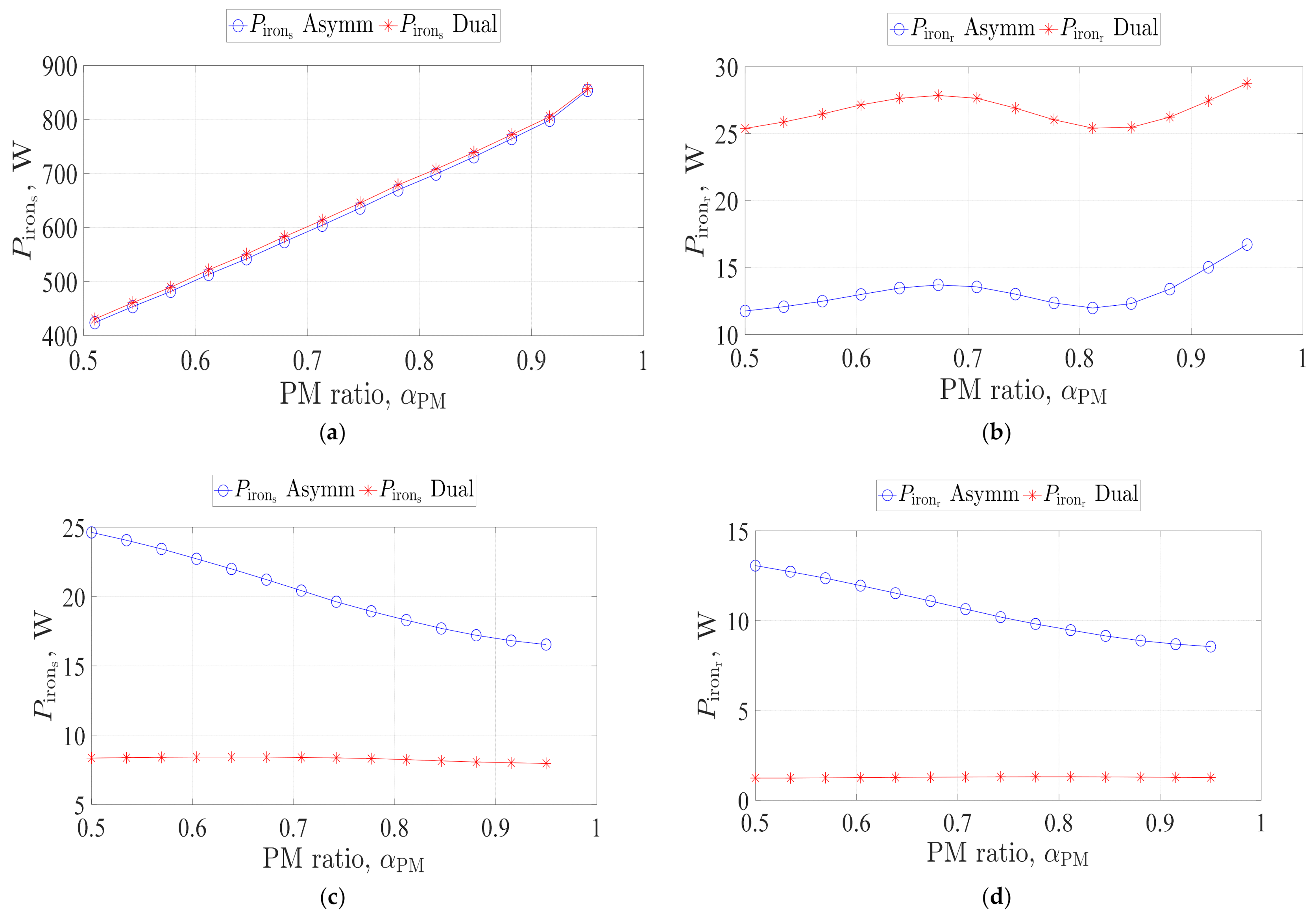
The PM width-to-pole pitch ratio, α P M , has a substantial effect on the average torque, torque ripple, and PM magnetic field intensity, as illustrated in Figure 9. In the propulsion mode, the average torque is proportional to α P M for the two winding configurations. Taking the dual three-phase configuration as an illustrative example, the average torque is 137.6 and 170.1 at α P M = 0.51 and 0.95, respectively. In that case, the torque ripple varies from 18.7 to 11.9 Nm, as shown in Figure 8b. In the charging mode, a slight change in the torque ripple with respect to the PM ratio can be noticed for the dual three-phase configuration, as shown in Figure 8d. Nevertheless, the torque ripple varies considerably between 15.5 Nm at α P M = 0.5 and 9.8 Nm at α P M = 0.95 when the asymmetrical six-phase topology is utilized. This reveals the superiority of the dual three-phase configuration under the charging mode of operation. A considerable change in the PM magnetic field intensity with the PM ratio can be seen in Figure 8e,f, respectively, under the propulsion and charging modes of operation.
By increasing α P M , the core losses increase proportionally for both winding layouts under the propulsion mode, as shown in Figure 10. In the charging mode, for the dual three-phase configuration, the core losses can be considered constant. Meanwhile, a considerable change in the core losses with respect to various PM magnet width-to-pole pitch ratios can be noticed in the case where the asymmetrical six-phase layout is employed. For instance, the stator core loss reaches 24.6 W at α P M = 0.5 compared to 16.5 W at α P M = 0.95. Similarly, the higher the PM magnet ratio, the lower the rotor core loss. It can be noted that the core losses are considerably low for the dual three-phase-based topology when compared with the asymmetrical six-phase-based one, as shown in Figure 10c,d.

4.3. Optimal Machine Selection

It is now possible to define the best design parameters at which the optimum trade-off between the average torque, torque ripple, and core losses can be achieved under various operational modes based on the Pareto optimization technique. The cost values of the Pareto technique constitute the average torque T m e a n , the torque ripple T r i p p l e , and the rotor core loss P i r o n r in the propulsion mode; correspondingly, they are the torque ripple T r i p p l e , the stator core loss P i r o n s , and the rotor core loss P i r o n r under the charging mode. The optimization results for the PM machine employing both the asymmetrical six-phase and the dual three-phase winding arrangements are depicted in Figure 11 and Figure 12, respectively. The optimal point (highlighted in green) is efficiently achieved according to the optimum trade-off between the various objectives. The optimal design and machine parameters for the asymmetrical winding configuration are listed in Table 5. In the following section, the results of the MEC-based analytical model will be validated using FE analysis. The same optimized design values (i.e., t s o / τ s o = 0.15 and α P M = 0.88) are used for comparison between the asymmetrical six-phase and dual three-phase winding layouts.

5. Finite Element Validation

In this section, the optimal machine with the optimized slot opening ratio ( t s o / τ s o = 0.15), as well as optimum PM width-to-pole pitch ratio ( α P M = 0.88), has been validated using the ANSYS software (V19, ANSYS Inc., Canonsburg, PA, USA). The optimal machine with the two different winding configurations has been assessed under both motoring and charging operational modes using the design parameters outlined in Table 3 considering the new values of slot opening and PM width-to-pole pitch ratios. Table 6 reveals the differences between the analytical and FE models with respect to the average torque production, the peak-to-peak torque ripple, rms phase voltage, and core losses.
An absolute agreement between both models with respect to the developed torque and full-load phase voltage has been highlighted in Figure 13 and Figure 14, respectively, for the dual three-phase and asymmetrical six-phase configurations under the motoring mode. Figure 15 depicts that the average torque is nullified under the charging, which is a basic necessity of the integrated OBCs. In the charging process, a similarity between the FE model and the analytical one for the full-load voltage is shown in Figure 16, and both asymmetrical six-phase and dual three-phase configurations are assessed.
Furthermore, the electromagnetic forces are computed using the Maxwell stress tensor defined in [38]. The x and y force components F x and F y , respectively, are derived from the radial and circumferential forces F r and F θ , respectively. These components are deduced from the radial and circumferential flux densities B r and B θ , respectively. The equations describing F r and F θ are:
F r   = 1 μ o B r 2 B θ 2 2 ,       F θ   = 1 μ o B r B θ ,
where μ o is the vacuum permeability. The F x and F y components are computed by integrating the projection of F r and F θ on the x and y directions. The integration is done over an enclosed surface in the average air gap radius ( R g ) . The projection can be expressed as in (9):
F x   = 0 L e f f 0 2 π R g ( F r cos θ m F θ sin θ m ) d θ d z , F y   = 0 L e f f 0 2 π R g F r sin θ m + F θ cos θ m d θ d z ,
where θ m is the circumferential angle. Figure 17a,b show the force computations in the charging mode from the FE and the analytical model for the asymmetrical and dual three-phase machines, respectively. The comparison shows a good correspondence between both models for the dual three-phase machine.
In addition, the dual three-phase machine gives forces in the kilonewton range. This can lead to a reduction in the lifetime and may cause eccentricity in the long run. Hence, this affects the machine performance. However, for the asymmetric machine, the forces are low, up to 2.5 N. This means that the machine can exhibit a much higher loading without a reduction in the rotor or bearing lifetime.
Furthermore, efficiency maps for both optimal asymmetrical six-phase and dual three-phase winding layouts are presented in Figure 18. Both winding arrangements offer high efficiency at various loading points.

6. Conclusions

This paper thoroughly presents the performance of a SPM machine with two winding arrangements under both the propulsion and charging modes of operation. The design process of the optimal machine has been initially clarified. Then, the slot opening width t s o and PM width-to-pole pitch ratio α P M have been optimized with respect to many objectives such as the maximum average torque, minimum torque ripple, and minimum core losses. These purposes cannot be accomplished at a specific t s o and α P M . Therefore, the best compromise has been selected, in which the objectives are very close to their optimum values. Eventually, a finite element software package has been used to confirm the accuracy of the results obtained based on the analytical model. The following conclusions can be drawn:
  • The increase in the slot opening width results in a decrease in the average torque under propulsion. However, the torque ripple varies.
  • In the motoring mode, the higher the PM width-to-pole pitch ratio, the higher the developed average torque. Nevertheless, the torque ripple value changes randomly.
  • Under charging, both slot opening and PM ratios have significant effects on the torque ripple for the asymmetrical six-phase topology. However, a slight change in the torque ripple can be noticed for the dual three-phase one.
  • For both modes, the increase in the slot opening width is accompanied by an increase in the rotor core loss, albeit with a reduction in the stator core loss.
  • For the two winding arrangements, the core losses are proportional to the PM ratio under propulsion. However, the same conclusion cannot be drawn under the charging mode.
  • From the perspective of torque components and core losses, the asymmetrical six-phase winding configuration is superior when compared to the dual three-phase one in the motoring mode.
  • In the charging mode, the dual three-phase-based topology is best among the two winding arrangements concerning the torque components and core losses.
  • The forces during charging for the dual three-phase machine are much higher than those for the asymmetrical winding machine. Therefore, the dual three-phase machine is not recommended during the charging mode.
  • The study shows that charging at the rated machine current may increase the risk of magnet demagnetization. For the given design, the simulation results showed that the charging current should be less than 57% of the rated current to avoid possible magnet demagnetization. As a matter of fact, SPM machines are highly prone to magnet demagnetization compared to other rotor topologies. Future work is planned to extend the current study to other rotor types to determine the most suitable one for this application.

Author Contributions

Conceptualization, A.H., A.S.A.-K., and M.Y.M.; methodology, A.H. and A.S.A.-K.; software, A.H. and M.Y.M.; validation, A.H. and M.Y.M.; formal analysis, A.H., A.S.A.-K., and M.Y.M.; investigation, A.S.A.-K. and S.A.; resources, A.S.A.-K. and S.A.; data curation, A.H. and M.Y.M.; writing—original draft preparation, A.H., A.S.A.-K., and M.Y.M.; writing—review and editing, A.H., A.S.A.-K., M.Y.M., and S.A.; visualization, A.H. and A.S.A.-K.; supervision, A.S.A.-K. and S.A.; project administration, A.H., A.S.A.-K., and S.A.; funding acquisition, A.S.A.-K. and S.A. All authors have read and agreed to the published version of the manuscript.

Funding

This research received no external funding.

Institutional Review Board Statement

Not applicable.

Informed Consent Statement

Not applicable.

Data Availability Statement

Data are contained within the article.

Acknowledgments

This work was achieved by the financial support of ITIDAs ITAC collaborative funded project under the category type of advanced research projects (ARP) and grant number ARP2020.R29.7.

Conflicts of Interest

The authors declare no conflict of interest.

Nomenclature

m Number of phases
N s Number of slots
p Number of pole pairs
D s o Machine outer diameter ( mm )
D i Machine inner diameter ( mm )
λ Inner-to-outer diameter ratio
P n Rated power (kW)
n m Rated speed ( rpm )
T n Rated torque ( Nm )
f Frequency ( Hz )
η Efficiency ( % )
ζ Power density ( kW / m 3 )
K c u Copper filling factor
J r Current density ( A / m 2 )
B g Air gap flux density ( T )
g Air gap length ( mm )
K Φ Ratio of electrical loading on rotor and stator
K e EMF factor
K i Current waveform factor
K p Electrical power waveform factor
L e f f Stack length ( mm )
D g Air gap diameter ( mm )
K L Stack length-to-air gap diameter ratio
A s Stator electrical loading ( A / m )
V D C DC bus voltage ( V )
τ s o Slot pitch ( mm )
t s o Slot opening width ( mm )
α P M PM width-to-pole pitch ratio

References

  1. Kumar, R.R.; Alok, K. Adoption of electric vehicle: A literature review and prospects for sustainability. J. Clean. Prod. 2020, 253, 119911. [Google Scholar] [CrossRef]
  2. Alshahrani, S.; Khalid, M.; Al Muhaini, M. Electric Vehicles Beyond Energy Storage and Modern Power Networks: Challenges and Applications. IEEE Access 2019, 7, 99031–99064. [Google Scholar] [CrossRef]
  3. Metwly, M.Y.; Abdel-Majeed, M.S.; Abdel-Khalik, A.S.; Hamdy, R.A.; Hamad, M.S.; Ahmed, S. A Review of Integrated On-Board EV Battery Chargers: Advanced Topologies, Recent Developments and Optimal Selection of FSCW Slot/Pole Combination. IEEE Access 2020, 8, 85216–85242. [Google Scholar] [CrossRef]
  4. Shi, C.; Tang, Y.; Khaligh, A. A Single-Phase Integrated Onboard Battery Charger Using Propulsion System for Plug-in Electric Vehicles. IEEE Trans. Veh. Technol. 2017, 66, 10899–10910. [Google Scholar] [CrossRef]
  5. De Santiago, J.; Bernhoff, H.; Ekergård, B.; Eriksson, S.; Ferhatovic, S.; Waters, R.; Leijon, M. Electrical Motor Drivelines in Commercial All-Electric Vehicles: A Review. IEEE Trans. Veh. Technol. 2012, 61, 475–484. [Google Scholar] [CrossRef] [Green Version]
  6. Salem, A.; Narimani, M. A Review on Multiphase Drives for Automotive Traction Applications. IEEE Trans. Transp. Electrif. 2019, 5, 1329–1348. [Google Scholar] [CrossRef]
  7. Subotic, I.; Bodo, N.; Levi, E.; Jones, M. Onboard Integrated Battery Charger for EVs Using an Asymmetrical Nine-Phase Machine. IEEE Trans. Ind. Electron. 2015, 62, 3285–3295. [Google Scholar] [CrossRef]
  8. Metwly, M.Y.; Abdel-Majeed, M.S.; Abdel-Khalik, A.S.; Torki, M.; Hamdy, R.A.; Hamad, M.S.; Ahmed, S. IoT-Based Supervisory Control of an Asymmetrical Nine-Phase Integrated on-Board EV Battery Charger. IEEE Access 2020, 8, 62619–62631. [Google Scholar] [CrossRef]
  9. Xiao, Y.; Liu, C.; Yu, F. An Effective Charging-Torque Elimination Method for Six-Phase Integrated On-Board EV Chargers. IEEE Trans. Power Electron. 2020, 35, 2776–2786. [Google Scholar] [CrossRef]
  10. Subotic, I.; Bodo, N.; Levi, E. Integration of Six-Phase EV Drivetrains Into Battery Charging Process With Direct Grid Connection. IEEE Trans. Energy Convers. 2017, 32, 1012–1022. [Google Scholar] [CrossRef] [Green Version]
  11. Subotic, I.; Bodo, N.; Levi, E. An EV Drive-Train With Integrated Fast Charging Capability. IEEE Trans. Power Electron. 2016, 31, 1461–1471. [Google Scholar] [CrossRef] [Green Version]
  12. Zhang, Y.; Cao, W.; McLoone, S.; Morrow, J. Design and Flux-Weakening Control of an Interior Permanent Magnet Synchronous Motor for Electric Vehicles. IEEE Trans. Appl. Supercond. 2016, 26, 1–6. [Google Scholar] [CrossRef] [Green Version]
  13. Lu, C.; Ferrari, S.; Pellegrino, G. Two Design Procedures for PM Synchronous Machines for Electric Powertrains. IEEE Trans. Transp. Electrif. 2016, 3, 98–107. [Google Scholar] [CrossRef] [Green Version]
  14. El-Refaie, A.M. Fractional-Slot Concentrated-Windings Synchronous Permanent Magnet Machines: Opportunities and Challenges. IEEE Trans. Ind. Electron. 2010, 57, 107–121. [Google Scholar] [CrossRef]
  15. Zhu, S.; Cox, T.; Xu, Z.; Gerada, C. A novel 24-slots14-poles fractional-slot concentrated winding topology with low space harmonics for electrical machines. Energies 2018, 11, 1–6. [Google Scholar] [CrossRef]
  16. Reddy, P.B.; Huh, K.-K.; El-Refaie, A.M. Generalized Approach of Stator Shifting in Interior Permanent-Magnet Machines Equipped With Fractional-Slot Concentrated Windings. IEEE Trans. Ind. Electron. 2014, 61, 5035–5046. [Google Scholar] [CrossRef]
  17. Patel, V.I.; Wang, J.; Wang, W.; Chen, X. Six-Phase Fractional-Slot-per-Pole-per-Phase Permanent-Magnet Machines With Low Space Harmonics for Electric Vehicle Application. IEEE Trans. Ind. Appl. 2014, 50, 2554–2563. [Google Scholar] [CrossRef] [Green Version]
  18. Barcaro, M.; Bianchi, N.; Magnussen, F. Six-Phase Supply Feasibility Using a PM Fractional-Slot Dual Winding Machine. IEEE Trans. Ind. Appl. 2011, 47, 2042–2050. [Google Scholar] [CrossRef]
  19. Alberti, L.; Fornasiero, E.; Bianchi, N. Impact of the rotor yoke geometry on rotor losses in permanent-magnet machines. IEEE Trans. Ind. Appl. 2011, 48, 98–105. [Google Scholar] [CrossRef]
  20. Wang, D.; Wang, X.; Jung, S.-Y. Cogging Torque Minimization and Torque Ripple Suppression in Surface-Mounted Permanent Magnet Synchronous Machines Using Different Magnet Widths. IEEE Trans. Magn. 2013, 49, 2295–2298. [Google Scholar] [CrossRef]
  21. Okamoto, S.; Denis, N.; Kato, Y.; Ieki, M.; Fujisaki, K. Core loss reduction of an interior permanent-magnet synchronous motor using amorphous stator core. IEEE Trans. Ind. Appl. 2016, 52, 2261–2268. [Google Scholar] [CrossRef]
  22. Wang, J.; Yuan, X.; Atallah, K. Design Optimization of a Surface-Mounted Permanent-Magnet Motor With Concentrated Windings for Electric Vehicle Applications. IEEE Trans. Veh. Technol. 2012, 62, 1053–1064. [Google Scholar] [CrossRef]
  23. Dhulipati, H.; Ghosh, E.; Mukundan, S.; Korta, P.; Tjong, J.; Kar, N.C. Advanced Design Optimization Technique for Torque Profile Improvement in Six-Phase PMSM Using Supervised Machine Learning for Direct-Drive EV. IEEE Trans. Energy Convers. 2019, 34, 2041–2051. [Google Scholar] [CrossRef]
  24. Tiegna, H.; Amara, Y.; Barakat, G. Study of Cogging Torque in Axial Flux Permanent Magnet Machines Using an Analytical Model. IEEE Trans. Magn. 2014, 50, 845–848. [Google Scholar] [CrossRef]
  25. Tiegna, H.; Bellara, A.; Amara, Y.; Barakat, G. Analytical Modeling of the Open-Circuit Magnetic Field in Axial Flux Permanent-Magnet Machines With Semi-Closed Slots. IEEE Trans. Magn. 2012, 48, 1212–1226. [Google Scholar] [CrossRef]
  26. Hemeida, A.; Hannon, B.; Vansompel, H.; Sergeant, P. Comparison of Three Analytical Methods for the Precise Calculation of Cogging Torque and Torque Ripple in Axial Flux PM Machines. Math. Probl. Eng. 2016, 2016, 1–14. [Google Scholar] [CrossRef] [Green Version]
  27. Yeo, H.-K.; Lim, D.-K.; Woo, D.-K.; Ro, J.-S.; Jung, H.-K. Magnetic Equivalent Circuit Model Considering Overhang Structure of a Surface-Mounted Permanent-Magnet Motor. IEEE Trans. Magn. 2015, 51, 1–4. [Google Scholar] [CrossRef]
  28. Hemeida, A.; Lehikoinen, A.; Rasilo, P.; Vansompel, H.; Belahcen, A.; Arkkio, A.; Sergeant, P. A Simple and Efficient Quasi-3D Magnetic Equivalent Circuit for Surface Axial Flux Permanent Magnet Synchronous Machines. IEEE Trans. Ind. Electron. 2018, 66, 8318–8333. [Google Scholar] [CrossRef]
  29. Qu, R.; Lipo, T. Analysis and Modeling of Air-Gap and Zigzag Leakage Fluxes in a Surface-Mounted Permanent-Magnet Machine. IEEE Trans. Ind. Appl. 2004, 40, 121–127. [Google Scholar] [CrossRef]
  30. Di Barba, P.; Farina, M.; Savini, A. An improved technique for enhancing diversity in Pareto evolutionary optimization of electromagnetic devices. COMPEL Int. J. Comput. Math. Electr. Electron. Eng. 2001, 20, 482–496. [Google Scholar] [CrossRef]
  31. Kwon, M.; Choi, S. An Electrolytic Capacitorless Bidirectional EV Charger for V2G and V2H Applications. IEEE Trans. Power Electron. 2017, 32, 6792–6799. [Google Scholar] [CrossRef]
  32. Pillai, J.R.; Bak-Jensen, B. Integration of Vehicle-to-Grid in the Western Danish Power System. IEEE Trans. Sustain. Energy 2010, 2, 12–19. [Google Scholar] [CrossRef]
  33. Abdel-Khalik, A.S.; Ahmed, S.; Massoud, A.M. Performance Evaluation of an On-Board Integrated Battery Charger System Using a 12-Slot/10-Pole Surface-Mounted PM Propulsion Motor. In Proceedings of the 2017 9th IEEE-GCC Conference and Exhibition (GCCCE), Manama, Bahrain, 8–11 May 2017; pp. 1–9. [Google Scholar]
  34. Subotic, I.; Bodo, N.; Levi, E.; Dumnic, B.; Milicevic, D.; Katic, V. Overview of fast on-board integrated battery chargers for electric vehicles based on multiphase machines and power electronics. IET Electr. Power Appl. 2016, 10, 217–229. [Google Scholar] [CrossRef]
  35. Grunditz, E.A.; Thiringer, T. Performance Analysis of Current BEVs Based on a Comprehensive Review of Specifications. IEEE Trans. Transp. Electrif. 2016, 2, 270–289. [Google Scholar] [CrossRef]
  36. Huang, S.; Luo, J.; Leonardi, F.; Lipo, T.A. A general approach to sizing and power density equations for comparison of electrical machines. IEEE Trans. Ind. Appl. 1998, 34, 92–97. [Google Scholar] [CrossRef] [Green Version]
  37. Grandi, G.; Serra, G.; Tani, A. Space vector modulation of a seven-phase voltage source inverter. International Symposium on Power Electronics, Electrical Drives, Automation and Motion, 2006. SPEEDAM 2006; IEEE: New York, NY, USA, 2006; pp. 1149–1156. [Google Scholar] [CrossRef]
  38. Meessen, K.K.; Paulides, J.J.; Lomonova, E.E. Force Calculations in 3-D Cylindrical Structures Using Fourier Analysis and the Maxwell Stress Tensor. IEEE Trans. Magn. 2012, 49, 536–545. [Google Scholar] [CrossRef]
Figure 1. Typical six-phase integrated battery charger schematic and phasor diagrams. (a) Asymmetrical six-phase configuration, (b) phasor diagram under propulsion, and (c) phasor diagram under charging. (d) Dual three-phase configuration, (e) phasor diagram under propulsion, and (f) phasor diagram under charging.
Energies 14 01848 g001aEnergies 14 01848 g001b
Figure 2. Six-phase 12-slot/10-pole surface-mounted permanent magnet (SPM) winding arrangements: (a) Dual three-phase and (b) asymmetrical six-phase.
Energies 14 01848 g002
Figure 3. Magnetomotive force (MMF) harmonic spectra for six-phase 12-slot/10-pole SPM winding arrangements under propulsion mode: (a) Dual three-phase and (b) asymmetrical six-phase.
Energies 14 01848 g003
Figure 4. MMF harmonic spectra for six-phase 12-slot/10-pole SPM winding arrangements under charging mode: (a) Dual three-phase and (b) asymmetrical six-phase.
Energies 14 01848 g004
Figure 5. Flowchart of the design process.
Energies 14 01848 g005
Figure 6. Pareto front between efficiency and power density.
Energies 14 01848 g006
Figure 7. Torque profiles and maximum PM magnetic field intensity with respect to slot opening width. (a) Average torque under propulsion. (b) Torque ripple under propulsion. (c) Average torque under charging. (d) Torque ripple under charging. (e) Maximum magnetic field intensity in the PMs under propulsion. (f) Maximum magnetic field intensity in the PMs under charging.
Energies 14 01848 g007
Figure 8. Variation in stator and rotor core losses with slot opening width under various operational modes. (a) Stator iron losses under propulsion. (b) Rotor iron losses under propulsion. (c) Stator iron losses under charging. (d) Rotor iron losses under charging.
Energies 14 01848 g008
Figure 9. Torque profiles and maximum PM magnetic field intensity with respect to PM width-to-pole pitch ratio. (a) Average torque under propulsion. (b) Torque ripple under propulsion. (c) Average torque under charging. (d) Torque ripple under charging. (e) Maximum magnetic field intensity in the PMs under propulsion. (f) Maximum magnetic field intensity in the PMs under charging.
Energies 14 01848 g009
Figure 10. Variation in stator and rotor core losses with PM width-to-pole pitch ratio under various operational modes. (a) Stator iron losses under propulsion. (b) Rotor iron losses under propulsion. (c) Stator iron losses under charging. (d) Rotor iron losses under charging.
Energies 14 01848 g010
Figure 11. Optimization results of the three objectives for the asymmetrical six-phase machine under various operational modes: (a) Propulsion and (b) charging.
Energies 14 01848 g011
Figure 12. Optimization results of the three objectives for the dual three-phase machine under various operational modes: (a) Propulsion and (b) charging.
Energies 14 01848 g012
Figure 13. Torque profiles under propulsion mode. (a) Asymmetrical winding layout and (b) dual three-phase winding layout.
Energies 14 01848 g013
Figure 14. Phase voltage profiles under propulsion mode. (a) Asymmetrical winding layout and (b) dual three-phase winding layout.
Energies 14 01848 g014
Figure 15. Torque profiles under charging mode. (a) Asymmetrical winding layout and (b) dual three-phase winding layout.
Energies 14 01848 g015
Figure 16. Phase voltage profiles under charging mode. (a) Asymmetrical winding layout and (b) dual three-phase winding layout.
Energies 14 01848 g016
Figure 17. x-y electromagnetic forces on the rotor in the charging mode. (a) Asymmetrical winding layout and (b) dual three-phase winding layout.
Energies 14 01848 g017
Figure 18. Efficiency maps. (a) Asymmetrical winding layout and (b) dual three-phase winding layout.
Energies 14 01848 g018
Table 1. SPM machine design specifications.
e-Golf requirements
Rated power (kW)50
Rated speed (rpm)3000
Maximum speed (rpm)12,000
Line current peak value (A)63.8
Inputs
Number of phases6
Number of slots12
Number of poles10
Air gap flux density ( T )0.8
Stack length-to-air gap diameter ratio1
Stator electrical loading ( A / mm )12
Constraints
Required flux density ( T )1.5
Current density ( A / mm 2 ) 5
Copper filling factor0.5
DC bus voltage ( V )600
Minimum efficiency at rated speed95%
Assigned materials and masses
CoilCopper5.84 kg
Stator coreM235-35A46.51 kg
Rotor coreM235-35A18.2 kg
Rotor magnetNdFeb_1.262.87 kg
Table 2. SPM machine design specification range.
ParameterSymbolRange
Air gap flux density ( T ) B g 0.7–0.85
Stack length-to-air gap diameter ratio K L 0.5–2
Stator electrical loading ( A / m m ) A s 5–15
Table 3. SPM machines design parameters.
ParameterSymbolValue
slot/pole combination N s / 2 p 12-slot/10-pole
Stator outer diameter (mm) D s o 282.6
Stator inner diameter (mm) D s i 192.4
Stack length (mm) L e f f 221.5
Air gap length (mm) g 1
core back width (mm) Y s b 19.4
Depth of stator slot (mm) d s s 25.7
Slot-opening width (mm) t s o 8.1375
stator tooth-tang depth (mm) d 2 5.6
Rotor outer diameter (mm) D r o 190.4
Shaft diameter (mm) D s h a f t 142
Rotor disc thickness (mm) Y r 21.1
Magnet thickness (mm) Y m 3.1
Gap between magnets (mm) d p m 7.179
PM width-to-pole pitch ratio α P M 0.95
No. of turns per coil N t 10
rated rms current (A) I a 45.113
Phase resistance (Ω) R 0.03988
winding layer/coil pitch-Double layer/single
Table 4. Initial value and variation range of the design variables.
Design VariableRangeInitial Value
t s o / τ s o 0.05–0.490.2
α P M 0.5–10.95
Table 5. Optimal machine results.
Variable/ObjectiveInitial ValueOptimal Value
t s o / τ s o 0.20.15
α P M 0.950.88
T m e a n 172.33 Nm176 Nm
T r i p p l e (propulsion)35.9 Nm11.4 Nm
Stator P c o r e (propulsion)747.17 W743 W
Rotor P c o r e (propulsion)26.02 W14.6 W
T r i p p l e (charging)10.33 Nm8.6 Nm
Stator P c o r e (charging)16.4 W17 W
Rotor P c o r e (charging)8.65 W8.75 W
Table 6. Comparison of finite element (FE) and analytical models.
Asymmetrical Six-Phase TopologyDual Three-Phase Topology
OutputPropulsionCharigngOutputPropulsionCharigng
ANSYSMECANSYSMECANSYSMECANSYSMEC
T a v g   Nm 17517600 T a v g   Nm 16917000
T r i p p l e   Nm 1311.48.78.6 T r i p p l e   Nm 14.713.94.14.4
r m s   V p h   V 2172177.98.1 r m s   V p h   V 20920910.8810.62
P C o r e S t a t o r   W 71374317.317 P C o r e S t a t o r   W 7207527.88.07
P C o r e R o t o r   W 12.614.68.759 P C o r e R o t o r   W 23271.61.3
PM loss(W)39.3-11.3-PM loss(W)57.8-2.5-
Publisher’s Note: MDPI stays neutral with regard to jurisdictional claims in published maps and institutional affiliations.

