Abstract
An electric multiple unit (EMU) high-speed train is the dynamic load that degrades the power quality in an electric railway system. Therefore, a power quality improvement system using an active power filter (APF) must be considered. Due to the oscillating load current in the dynamic load condition, a fast and accurate harmonic current-tracking performance is required. As such, this paper proposes the design of a model predictive control (MPC) since the minimization of cost function in the MPC process can suitably determine APF switching states. The design technique of MPC is based on the APF mathematical model. This controller was designed to compensate the time delay in the digital control. Moreover, the synchronous detection (SD) method applied the reference current calculations, as shown in this paper. To verify the proposed MPC, the overall control of APF was implemented on a eZdsp F28335 board by using the hardware-in-the-loop technique. The testing results indicated that the proposed MPC can provide a fast and accurate harmonic current-tracking response compared with the proportional-integral controller. In the load changing condition, the MPC was still effective in providing a good result after compensation. The percentage of total harmonic distortion, the percentage current unbalance factor, and the power factor would also be kept within the IEEE Standard 519 and IEEE Standard 1459.
1. Introduction
Nowadays, electric multiple unit high-speed trains (EMU high-speed trains) are an important part of the transportation infrastructure. The power distribution system is the utility supply for EMU high-speed train drives. The EMU high-speed train consists of a single-phase rectifier, three-phase inverter, traction motor drive, facilities in the passenger compartment, and other loads. These components behave like a linear and non-linear load. These loads produce harmonic currents, unbalanced currents, and reactive power on the utility supply side. The degradation of power quality can lead to many disadvantages, such as power loss in transmission lines and power transformers [1,2]; the arcing [3] and irregularity [4] of the EMU’s pantograph; interference in the communication systems and electric railway signaling systems [5]; electromagnetic interference of electric devices [6]; malfunction of the device [7]; and protective device failures and short-life electric devices [8]. In [9,10], the EMU-high speed train works in three typical situations. The first situation is during accelerating startup. This situation results in a fast increase in the load current. In the second situation, the EMU high-speed train moves away at a constant speed. The load current is invariable. The last situation is a braking. In this situation, the load current decreases rapidly. Thus, the load current behavior of the electric railway system is dynamically varied, which significantly affects the power quality in the transient condition. The undesirable effects on the power system, power equipment, and adjacent loads may occur. The reliability requirements of power distribution systems are necessary. Consequently, the power quality improvement in the electric railway system must be examined.
By considering the power quality conditioning in railway electrification, there are many techniques, such as static VAR compensators (SVC) [11], static synchronous compensators (STATCOM) [12], passive power filter (PPF) [13], active power filter (APF) [14], and hybrid power filter (HPF) [15]. The SVC and STATCOM are used for the imbalance current and reactive power compensations. Nevertheless, SVC and STATCOM cannot mitigate the harmonic. The PPF are widely installed in the system to mitigate the main harmonics for large loads, but the current balancing cannot be achieved using this technique. PPF parameters are designed to mitigate the harmonic at the specific frequency (resonance frequency). In the case of load changing, these parameters should be redesigned to maintain good compensation performance. It should be noted that the PPF are not suitable for dynamic load conditions, especially for EMU high-speed trains.
The APF can compensate both for imbalanced currents and reactive power, as well as perform harmonic mitigation. To solve the aforementioned problems, an APF is a suitable power filter for the electric railway system [16]. The APF would provide a faster dynamic response, higher compensation performance, and more flexibility compared with the SVC, STATCOM, PPF, and HPF. Therefore, the power quality improvement of an electric railway system using the APF is intensively studied in this paper.
The harmonic mitigation topology in an electric railway system using APF is shown in Figure 1. It is well known that the compensating current control is an important part of the APF system. Therefore, from the literature survey, it was found that there are several strategies to control the compensating current injection. In the electric railway system, the hysteresis control was applied for the harmonic mitigation in the electric railway system [17]. This control has a fast dynamic response, simplicity, and is also insensitive to the model and system parameter variations. However, the hysteresis operation provides an oscillating and high switching frequencies. It can cause the compensating current ripple. Moreover, the frequency rating of the devices (IGBTs, MOSFETs, etc.) and the heating due to switching losses must be considered for practical work. For an APF with another system, the PI controller [18] is widely used to control the compensating current. It has the proportional and integral terms. These terms offer good transient and steady state responses. However, the parameter design of the PI controller is based on a mathematical model of the system. Here, the harmonic current-tracking performance is affected during a variation of the system parameters. A proportional resonant (PR) controller is also applied for the APF control [19]. The PR controller parameters can be tuned for the specific harmonic frequency. This point has good tracking performance between the compensating current and the reference current at the selected harmonic frequency. However, the harmonic components may occur at any frequency. Thus, excellent harmonic current tracking performance cannot be completely achieved by the PR controller. In addition, in a three-phase four-wire system, a repetitive (RT) controller [20] was adopted. This controller can provide the steady-state tracking accuracy for the harmonic current control. Due to the periodic operation by the RT mechanism, the harmonic current will not be exactly compensated in the transient condition. Moreover, the stability analysis of the RT controller has become a serious problem in the design process.
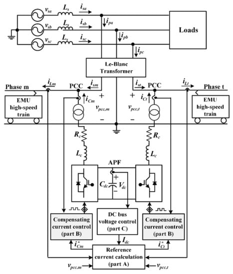
Figure 1.
The structure of electric railway system and the control strategy of the harmonic mitigation system using an active power filter (APF). EMU: electric multiple unit (EMU); PCC: point of common coupling.
From the presentation in [9,10], the load current of electric railway systems fluctuates along with the traffic situation. From the load current fluctuation, a suitable compensating
Current controller of the APF in the electric railway system must have a fast dynamic response according to the load current behavior. In recent years, the MPC is extensively used for power electronics converters because of the advantages of high control accuracy and fast dynamic response [21]. Therefore, the MPC is suitable for compensating the APF current control. Processing and sampling delays exist in a digital control. Here, the MPC can compensate for these delays. The mechanism of this controller can be designed to predict future switching states for the converter. The stability-constrained of the MPC controller is well-proven in [22]. In this work, the MPC was used to improve the performance of the APF compensating current control in an electric railway system. Moreover, the MPC compensating current control in the electric railway system was not found in any of the previous research.
This paper is structured as follows: Section 2 describes the structure of electric railway systems and the APF control strategy. The reference current calculation using the SD method is presented in Section 3. Then, the compensating current control based on the MPC is discussed in detail in Section 4. Section 5 presents the configuration of the HIL simulation technique. The testing results of the harmonic mitigation and discussions are described in Section 6. Finally, Section 7 concludes this work.
2. Active Power Filter Topology in an Electric Railway System.
The structure of an electric railway system is depicted in Figure 1. The Le-Blanc transformer is utilized to step down the voltage level from 69 kV (three-phase voltage source) to 26 kV (two single-phase voltage source). The phase angle difference of the two single-phase power system between phase m and phase t is 90 degrees. These voltages are used to drive the EMU high-speed train. The advantage of using a Le-Blanc transformer is the voltage source balancing at phase m and phase t. The non-linear load characteristics of the electric railway system can be found in [23].
The APF circuit topology in the electric railway systems consists of voltage source inverters (VSIs). The two VSIs are connected back -to-back through a common DC capacitor (). The VSIs are connected to the step-down side of the transformer through the line impedance at phase m and phase t (). These VSIs act as a source to inject the compensating currents into the point of common coupling (PCC). An APF control strategy would directly have an impact on the performance of the power quality enhancement. Therefore, this point has been continuously developed. An APF control strategy in an electric railway system, as shown in Figure 1, consists of the reference current calculation (part A), the DC bus voltage control (part B), and the compensating current control (part C). By considering “part A” from previous publications, there are many methods for the reference calculation [24,25,26]. In this work, the SD method was proposed. This method can calculate an accurate harmonic current. The calculation procedure of the SD method is simple. It results in a fast computational time. In the literature review, the DC bus voltage level for APFs [12,15,16,18] and power converter circuits [27,28] is commonly regulated by a PI controller because the steady-state accuracy for the DC bus voltage control was considered. From the previous work [29], the DC bus voltage control loop using the PI controller was suitably designed. Therefore, the PI controller parameters and the reference DC bus voltage in [29] are defined for DC bus voltage control in part B. Finally, part C is the compensating current control, which significantly affected the injection performance of the compensating current. The purpose of this part was to design a controller to track the compensating current with the least error possible. The harmonic mitigation, power factor correction, and load balancing can be achieved efficiently by the improvement of the control strategy.
3. Reference Current Calculation
The SD method is used to calculate the reference currents () for the compensating current controls. The SD method applied in the three-phase power system was firstly proposed in 1992 by Lin et al. [30]. For this method, the computational capability of the reference currents is simple. Here, it can provide a fast calculation time. This approach is suitable for the real-time implementation on a digital signal processing (DSP) board. From the prominent point explained above, the SD method is applied to calculate the in this work. The calculation procedure of the reference currents by the SD method can be summarized by the block diagram in Figure 2. There are four steps to calculate the :
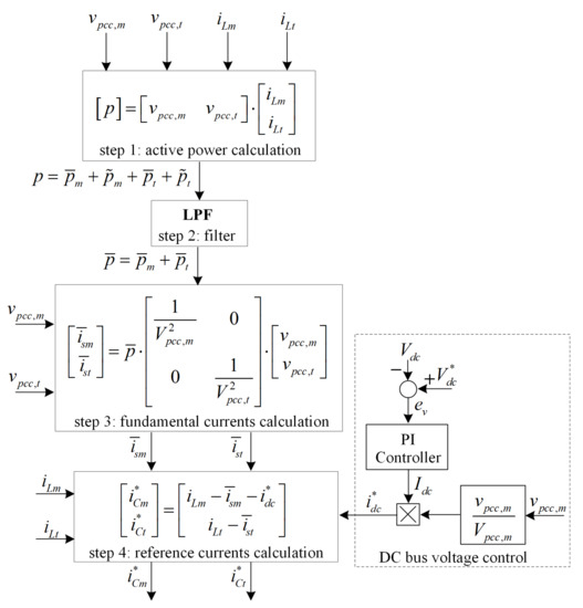
Figure 2.
The block diagram of SD method for the APF in electric railway system.
Step 1: Calculate the instantaneous power of the EMU high-speed train () using Equation (1). The assumption of this method is that the equal average power have to be obtained after compensation. The can be separated in terms of DC components () and AC components (). The DC and AC terms mean that there are the fundamental and harmonic components, respectively:
Step 2: Calculate the fundamental component of the instantaneous power (). The low-pass filter (LPF) is chosen to draw the from the . In this work, the cutoff frequency of LPF is equal to 60 Hz.
Step 3: Calculate the fundamental currents () by Equation (2):
where are the amplitude of the single-phase source voltages for each phase.
Step 4: Calculate the for the compensating current controls using Equation (3):
4. Compensating Current Control System with Model Predictive Control
4.1. Principle of a MPC
The controller’s delay time is an important issue with digital control because of the performance improvement in the transient condition. Therefore, the time delay compensation is concerned with the digital controller. The MPC has an ability to predict the next switching states of the converter over a fixed set time horizon, and also compensate the digital time delay. The operation of MPC is based on a system behavior prediction using a mathematical model. The measured values of the system in their present states are required for the predictive data. In addition, the minimization of cost function is a part of the MPC mechanism. This function determines suitably the converter’s switching states. Therefore, this controller can provide a fast dynamic response and high control performance. The MPC approach, when applied to the APF compensating current control, is depicted in Figure 3, and can be divided into three principle components: the reference current prediction, the compensating current prediction, and the minimization of cost function. In this work, the MPC design is based on the APF switching state prediction using a mathematical model. The computational burden of the control platform and the DSP board operation leads to a processing delay of two sampling periods [31]. To compensate for the delay time in the computational of the control platform and the DSP board operation, the predictions are determined at the time n + 2. The prediction process uses the measured values of the system at the time n (present states). In addition, the minimization of cost function is a part of MPC mechanism.
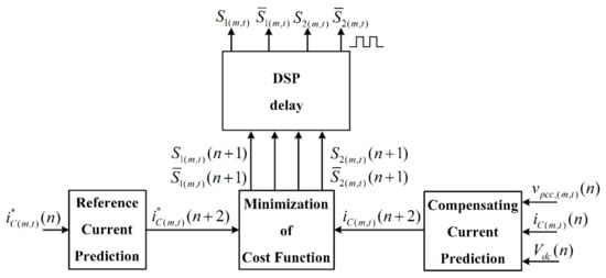
Figure 3.
The model predictive control for compensating current control system. DSP: digital signal processing.
4.2. The Reference Current Prediction
The calculated via the SD method is the reference currents at the time instant n (). However, the computational burden of the control platform and the DSP board operation leads to a processing delay for the two sampling periods. In order to compensate for the processing delay, the reference currents prediction at the time instant n + 2 () must be taken into account in the MPC approach. Moreover, ref. [32] presents the use of the first-order Lagrange method, which can provide a good performance for the reference current prediction. Thus, the first-order Lagrange method is used to predict the in this paper. By considering the calculated from the SD method, the reference currents at the previous time instant n − 1 () and are derived using the linear-type prediction. The can be expressed as Equation (4):
4.3. The Compensating Current Prediction
The APF circuit structure, as shown in Figure 4, is firstly considered to study the compensating current prediction. According to Figure 4, the APF operation is to inject the compensating currents () from the APF bus to the PCC bus through a linear transformer. The differential equation of the compensating currents () are adopted for the process of the compensating the current prediction. Therefore, the differential equation of the APF in Equation (5) is considered:
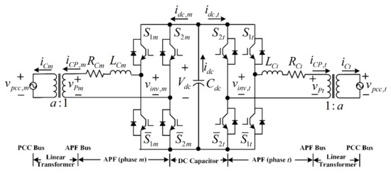
Figure 4.
The structure of APF in electric railway systems.
Here, the forward Euler formula is used to approximate the term. The can be considered as the discrete time model in Equation (6). The compensating current of the next sampling period () are obtained, as in Equation (7), where the and are the APF output voltage and the inverter output voltage at the time instant n, respectively. are equal to . Further, is a conversion ratio of the linear transformer:
We note that the processing delay compensation is necessary to achieve the fast dynamic response and precise current tracking. The compensating current prediction at the time instant n + 2 () are to compensate for the processing delay. Here, it has the ability to eliminate the current tracking error at the next sampling period. Therefore, is shifted forward to , as in Equation (8):
In addition, can follow a similar procedure as the one mentioned above. These values are calculated by Equation (9):
From Equation (9), the inverter output voltage prediction at the time instant n + 1 () in Equation (10) relates to the switching states of the APF () and the DC bus voltage () at the time instant n:
4.4. The Minimization of Cost Function
The main objective of this work was to reduce the tracking errors between and . Therefore, the absolute errors between and are the cost function (). The smallest of value is used to select the switching state for the minimum errors between and . The time horizon of the cost function is the possible switching states of APF. The can be defined by Equation (11), which the equal to :
The compensating currents are predicted by considering the APF switching states. The VSIs was studied. The possible switching states can be categorized into four cases, as listed in Table 1. This assumes that an inverted pair of signals is provided to the two switches connected to each converter leg. The switching state at the time instant n + 2 can provide the smallest value of . This switching state is applied at the next sampling period. The whole process of MPC can be summarized using a flow diagram, as shown in Figure 5.

Table 1.
The possible switching states of APF.
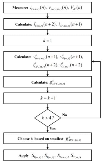
Figure 5.
The MPC flow diagram for each sampling period.
5. Hardware-in-the-Loop (HIL) Simulation
In this work, we focused on the design and development of the MPC to improve current control APF performance. We introduced a harmonic mitigation system for electric railway systems. To first prove the enhanced approach and to clearly investigate its performance before the real experimental platform setup, the HIL technique was applied for validation. The overall control strategy improved in this work was implemented digitally in the eZdsp F28335 board. The considered harmonic mitigation system in the electric railway system was simulated using the MATLAB/Simulink program, while the reference current calculation was simulated using the SD method, the compensating current controls with the MPC controller, and the DC bus voltage control with the PI controller written in C programming languages using the code composer studio (CCStudio) software on the eZdsp F28335 board. The MATLAB/Simulink program in the host computer and the CCStudio software in the eZdsp F28335 board were interfaced by the JTAG emulator, as depicted in Figure 6. The blocks in Simulink called “From RTDX” and “To RTDX” were used to send and receive data between MATLAB/Simulink program and eZdsp F28335 board, respectively. Note that the HIL simulation setup was achieved by opening the operating mode of the TMS320 F28335 card and the J9 jumper on the docking station.
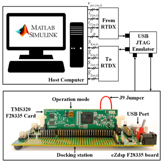
Figure 6.
The configuration of the hardware-in-the-loop (HIL) simulation.
The HIL simulation model used to test the performance of the harmonic mitigation is shown in Figure 7. The PCC voltages (), load currents (), compensating currents (), and DC bus voltage () were measured from the considered power systems. These data were sent to the target of eZdsp F28335 with the “From RTDX” block, and were calculated in the overall control strategy to generated the pulses (). were transferred into the host computer via the “To RTDX” block. were used to switch the IGBTs of the APF for the compensating current injection control.
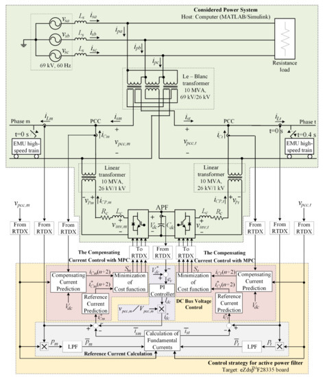
Figure 7.
The HIL simulation model for the harmonic mitigation using the APF in the electric railway system.
6. Results and Discussion
From the HIL model presented above, the performance comparison study between the conventional PI controller [29] and the proposed MPC for the compensating current control is herein discussed. The harmonic mitigation in the electric railway system was tested in two situations. In situation 1, at t = 0–0.4 s, the balanced loads of EMU high-speed train was considered. In situation 2, at t = 0.4–0.7 s, the balanced loads were changed to the unbalanced loads. The harmonic producing load in this situation was extremely changed for the electric railway system. This was found in the case of a fault of the electrical system. The performance evaluation of the controllers tested in this system were classified into two categories: the tracking of the compensating current control and APF performance.
6.1. The Tracking Performance of the Compensating Current Control
The aim of the compensating current control was to reduce the errors between the and the . The tracking performance of the currents between and controlled by the PI controller and the MPC can be seen in Figure 8. According to the waveforms in Figure 8, the MPC can control to track , as calculated the SD method. The results confirmed that the MPC can provide a small tracking error compared with the PI controller, even though the load currents of the EMU high-speed train were changed. In addition, the MPC provided a faster dynamic response than the PI controller, which can be seen from Figure 8 at the t = 0.4 s. In the load changing situation, the high oscillating current from PI controller can cause a problem in the system.
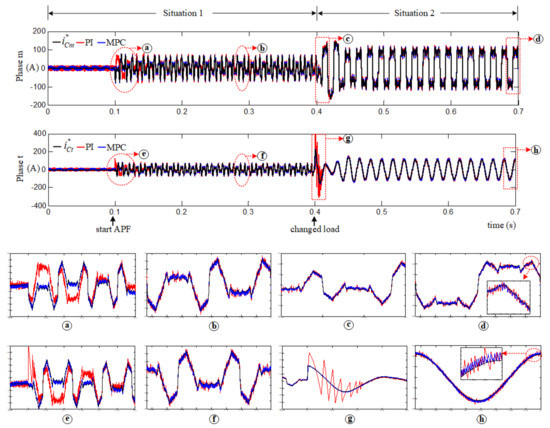
Figure 8.
The tracking performance of the compensating currents.
6.2. The Performance of APF
EMU-high speed train loads can generate harmonic and unbalanced source currents. The performance indices for the harmonic mitigation in the electric railway system are the average total harmonic distortion of source currents () [33], the current unbalanced factor (%CUF) [34], and the power factor (PF). The testing results of the harmonic mitigation based on the MPC in Figure 9 show that the proposed controller can efficiently control the compensating currents. The performance indices of the harmonic mitigation are completely addressed in Table 2.
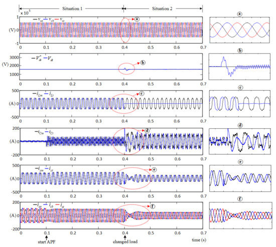
Figure 9.
The testing results of the harmonic mitigation performance in the electric railway system using the MPC.
Table 2.
The performance indices of the harmonic mitigation.
Before compensation, the waveforms of depended on nonlinear loads. These resulted in the source current distortion. The values of these currents in situations 1–2 were equal to 21.46% and 21.63%, respectively. These values were much higher than the IEEE Std. 519–2014. Before compensation, the %CUF values for situations 1–2 were equal to 0.00% and 95.45%, respectively. The %CUF for the situation 2 was much greater than the IEEE Std. 1459–2010. In situations 1–2, the PF before compensation were equal to 0.97 and 0.70, respectively.
After compensation, the APF injected the into the PCC at 0.1 s. The became a more sinusoidal waveform, which caused the waveforms of to nearly become a sinusoidal waveform, as shown in Figure 9. The %THDav results of the controller testing are shown in Table 2. As a result, in situations 1–2, the MPC provides a small %THDav compared with the PI controller. The unbalanced source current in situation 2 became balanced source current. According to situation 2, after compensation, the %CUF value from the MPC was less than the PI controller. Nevertheless, the PI controller and MPC provided good PF correctio. For the DC bus voltage control, the PI controller was sufficient to regulate the DC bus voltage (). The PI controller parameters ( and ) [29] were defined for the DC bus voltage loop control. From Figure 9, it can be seen that the is kept constant at the using the PI controller.
7. Conclusions
The APF control based on the MPC in the electric railway system was completely presented in this paper. The SD method was applied for an APF reference current calculation. In order to compensate the processing delay for the MPC, the compensating current prediction at the time instant n+2 was designed. A fast transient response and steady-state tracking accuracy for the compensating current control was accomplished. The overall control strategy of APF was implemented on the eZdsp F28335 board. The HIL results were mentioned. The proposed MPC design clearly provides an excellent dynamic response in the load changing condition. The %THDav and %CUF follows in the IEEE standard 519 and IEEE standard 1459, respectively. Moreover, this approach can provide the unity power factor. In future work, the control platform implemented on the eZdsp F28335 board is necessary for the experimental setup of APF in electric railway systems.
Author Contributions
C.P., K-L.A. (Kongpol Areerak) and S.S.Y. proposed the idea, completed the methodology analysis, and improved the current controller; C.P. analyzed data and performed the simulation; All authors participated in the conceptualization, methodology, and writing—review and editing. All authors have read and agreed to the published version of the manuscript.
Funding
This work was supported by the Thailand Research Fund (TRF), the Royal Golden Jubilee Ph.D program (RGJ: grant number PHD/0019/2560).
Conflicts of Interest
The authors declare no conflict of interest.
References
- Weijun, L.; Qinghao, W.; Jingzhong, L.; Chenyang, L.; Zhitong, L.; Yi, W.; Xiangqun, Z. Research on transmission line power losses effected by harmonics. In Proceedings of the 2016 China International Conference on Electricity Distribution (CICED), Xi’an, China, 10–13 August 2016. [Google Scholar] [CrossRef]
- Song, W.; Fang, J.; Jiang, Z.; Staines, M.; Badcock, R. AC Loss Effect of High-Order Harmonic Currents in a Single-Phase 6.5 MVA HTS Traction Transformer. IEEE Trans. Appl. Supercond. 2019, 29, 550145. [Google Scholar] [CrossRef]
- Guo, L.; Gao, X.; Li, Q.; Huang, W.; Shu, Z. Online Antiicing Technique for the Catenary of the High-Speed Electric Railway. IEEE Trans. Power Del. 2015, 30, 1569–1576. [Google Scholar] [CrossRef]
- Song, Y.; Liu, Z.; Rønnquist, A.; Nåvik, P.; Liu, Z. Contact Wire Irregularity Stochastics and Effect on High-Speed Railway Pantograph–Catenary Interactions. IEEE Trans. Instrum. Meas. 2020, 69, 8196–8206. [Google Scholar] [CrossRef]
- Foley, F.J. The impact of electrification on railway signalling systems. In Proceedings of the 5th IET Professional Development Course on Railway Electrification Infrastructure and Systems, London, UK, 6–9 June 2011; pp. 146–153. [Google Scholar] [CrossRef]
- Charalambous, C.A.; Demetriou, A.; Lazari, A.L.; Nikolaidis, A.I. Effects of Electromagnetic Interference on Underground Pipelines Caused by the Operation of High Voltage AC Traction Systems: The Impact of Harmonics. IEEE Trans. Power Del. 2018, 33, 2664–2672. [Google Scholar] [CrossRef]
- Brumsickle, W.E.; Divan, D.M.; Luckjiff, G.A.; Freeborg, J.W.; Hayes, R.L. Power Quality and Reliability. IEEE Ind. Appl. Mag. 2005, 11, 48–53. [Google Scholar] [CrossRef]
- IEEE. IEEE Recommended Practices and Requirements for Harmonic Control in Electrical Power Systems. IEEE Standard 519–1992. 1993. Available online: https://ieeexplore.ieee.org/servlet/opac?punumber=2227 (accessed on 1 April 2021).
- Yu-quan, L.; Guo-pei, W.; Huang-sheng, H.; Li, W. Research for the effects of high-speed electrified railway traction load on power quality. In Proceedings of the 2011 4th International Conference on Electric Utility Deregulation and Restructuring and Power Technologies (DRPT), Weihai, China, 6–9 July 2011; pp. 569–573. [Google Scholar] [CrossRef]
- Gazafrudi, S.; Langerudy, A.; Fuchs, E.; Al-Haddad, K. Power Quality Issues in Railway Electrification: A Comprehensive Perspective. IEEE Trans. Ind. Electron. 2015, 62, 3081–3090. [Google Scholar] [CrossRef]
- Zhu, G.; Chen, J.; Liu, X. Compensation for the negative-sequence currents of electric railway based on SVC. In Proceedings of the 2008 3rd IEEE Conference on Industrial Electronics and Applications, Singapore, 3–5 June 2008; pp. 1958–1963. [Google Scholar] [CrossRef]
- ElGebaly, A.E.; Hassan, A.E.-W.; El-Nemr, M.K. Reactive Power Compensation by Multilevel Inverter STATCOM for Railways Power Grid. In Proceedings of the 2019 IEEE Conference of Russian Young Researchers in Electrical and Electronic Engineering (EIConRus), Saint Petersburg and Moscow, Russia, 28–31 January 2019; pp. 2094–2099. [Google Scholar] [CrossRef]
- Hu, H.; He, Z.; Gao, S. Passive Filter Design for China High-Speed Railway With Considering Harmonic Resonance and Characteristic Harmonics. IEEE Trans. Power Del. 2015, 30, 505–514. [Google Scholar] [CrossRef]
- Sun, Z.; Jiang, X.; Zhu, D.; Zhang, G. A Novel Active Power Quality Compensator Topology for Electrified Railway. IEEE Trans. Power Electron. 2004, 19, 1036–1042. [Google Scholar] [CrossRef]
- Lao, K.-W.; Wong, M.-C.; Dai, N.Y.; Wong, C.-K.; Lam, C.-S. A Systematic Approach to Hybrid Railway Power Conditioner Design with Harmonic Compensation for High-Speed Railway. IEEE Trans. Power Electron. 2015, 62, 930–942. [Google Scholar] [CrossRef]
- He, Z.; Zheng, Z.; Hu, H. Power quality in high-speed railway systems. Int. J. Rail Transp. 2016, 4, 71–97. [Google Scholar] [CrossRef]
- Luo, A.; Wu, C.; Shen, J.; Shuai, Z.; Ma, F. Railway Static Power Conditioners for High-speed Train Traction Power Supply Systems Using Three-phase V/V Transformers. IEEE Trans. Power Electron. 2011, 26, 2844–2856. [Google Scholar] [CrossRef]
- Trinh, Q.-N.; Lee, H.-H. An Advanced Current Control Strategy for Three-Phase Shunt Active Power Filters. IEEE Trans. Ind. Electron. 2013, 60, 5400–5410. [Google Scholar] [CrossRef]
- Herman, L.; Papic, I.; Blazic, B. A proportional-resonant current controller for selective harmonic compensation in a hybrid active power filter. IEEE Trans. Power Del. 2014, 29, 2055–2065. [Google Scholar] [CrossRef]
- Santiprapan, P.; Booranawong, A.; Areerak, K.-L.; Saito, H. Adaptive repetitive controller for an active power filter in three-phase four-wire systems. IET Power Electron. 2020, 13, 2756–2766. [Google Scholar] [CrossRef]
- Kouro, S.; Perez, M.A.; Rodriguez, J.; Llor, A.M.; Young, H.A. Model Predictive Control: MPC’s Role in the Evolution of Power Electronics. IEEE Ind. Electron. Mag. 2015, 9, 8–21. [Google Scholar] [CrossRef]
- Cheng, X.; Krogh, B.H. Stability-constrained model predictive control. IEEE Trans. Auto. Control. 2001, 46, 1816–1820. [Google Scholar] [CrossRef]
- Huang, S.-R.; Chen, B.-N. Harmonic study of the Le Blanc transformer for Taiwan railway’s electrification system. IEEE Trans. Power Del. 2002, 17, 495–499. [Google Scholar] [CrossRef]
- Akagi, H.; Kanazawa, Y.; Nabae, A. Instantaneous Reactive Power Compensators Comprising Switching Devices without Energy Storage Components. IEEE Trans. Ind. Appl. 1984, IA-20, 625–630. [Google Scholar] [CrossRef]
- Sujitjorn, S.; Areerak, K.-L.; Kulworawanichpong, T. The DQ Axis with Fourier (DQF) Method for Harmonic Identification. IEEE Trans. Power Del. 2007, 22, 737–739. [Google Scholar] [CrossRef]
- Santiprapan, P.; Areerak, K.-L.; Areerak, K.-N. A Novel Harmonic Identification Algorithm for the Active Power Filters in Non-Ideal Voltage Source Systems. J. Power Electron. 2017, 17, 1639–1649. [Google Scholar] [CrossRef]
- Hosseinzadeh, M.; Salmasi, F.R. Robust Optimal Power Management System for a Hybrid AC/DC Micro-Grid. IEEE Trans. Sust. Energy 2015, 6, 675–687. [Google Scholar] [CrossRef]
- Schonbergerschonberger, J.; Duke, R.; Round, S.D. DC-Bus Signaling: A Distributed Control Strategy for a Hybrid Renewable Nanogrid. IEEE Trans. Power Electron. 2006, 53, 1453–1460. [Google Scholar] [CrossRef]
- Panpean, C.; Areerak, K.-L.; Areerak, K.-N.; Udomsuk, S.; Santiprapan, P. The Harmonic Detection for Co-Phase Railway System in Distorted Voltage Source Condition. In Proceedings of the 2019 16th International Conference on Electrical Engineering/Electronics, Computer, Telecommunications and Information Technology (ECTI-CON), Pattaya, Thailand, 10–13 July 2019; pp. 545–548. [Google Scholar] [CrossRef]
- Lin, C.E.; Chen, C.L.; Huan, C.L. Calculating approach and implementation for active filters in unbalanced three phase system using synchronous detection method. In Proceedings of the 1992 International Conference on Industrial Electronics, Control, Instrumentation, and Automation, San Diego, CA, USA, 13 September 1992; pp. 374–380. [Google Scholar] [CrossRef]
- Cortes, P.; Rodriguez, J.; Silva, C.; Flores, A. Delay Compensation in Model Predictive Current Control of a Three-Phase Inverter. IEEE Trans. Ind. Electron. 2012, 59, 1323–1325. [Google Scholar] [CrossRef]
- Odavic, M.; Biagini, V.; Zanchetta, P.; Sumner, M.; Degano, M. One-sample-period-ahead predictive current control for high-performance active shunt power filters. IET Power Electron. 2011, 4, 414–423. [Google Scholar] [CrossRef]
- IEEE. IEEE Recommended Practice and Requirements for Harmonic Control in Electric Power Systems. IEEE Standard 519. 2014. Available online: https://ieeexplore.ieee.org/servlet/opac?punumber=6826457 (accessed on 1 April 2021).
- IEEE. IEEE Standard Definitions for the Measurement of Electric Power Quantities under Sinusoidal, Nonsinusoidal, Balanced, or Unbalanced Conditions; IEEE Standard 1459; IEEE: Piscataway, NJ, USA, 2010; p. 7586362. [Google Scholar]


Publisher’s Note: MDPI stays neutral with regard to jurisdictional claims in published maps and institutional affiliations. |
© 2021 by the authors. Licensee MDPI, Basel, Switzerland. This article is an open access article distributed under the terms and conditions of the Creative Commons Attribution (CC BY) license (https://creativecommons.org/licenses/by/4.0/).