Article

Review of Legal Aspects of Electrical Power Quality in Ship Systems in the Wake of the Novelisation and Implementation of IACS Rules and Requirement

Department of Ship Electrical Power Engineering, Faculty of Marine Electrical Engineering, Gdynia Maritime University, Morska St. 83, 81-225 Gdynia, Poland
*
Author to whom correspondence should be addressed.
Energies 2021, 14(11), 3151; https://doi.org/10.3390/en14113151
Submission received: 16 April 2021 / Revised: 20 May 2021 / Accepted: 24 May 2021 / Published: 28 May 2021
(This article belongs to the Special Issue Power Quality in Electrified Transportation Systems)

Abstract

:
This paper deals with new challenges regarding power quality in ship technology resulting from the novelisation and implementation of IACS (International Association of Classification Societies) rules and requirements. These rules, known as IACS E24 2016/2018, address harmonic distortion for ship electrical distribution systems, including harmonic filters. The reasons for the legislative changes based on a short overview of power quality-related accidents are discussed, after which a brief presentation of the updated IACS rules illustrated by a related DNV GL (Det Norske Veritas Germanischer Lloyd) case study is shown. A key part of this paper includes proposals concerning harmonics and interharmonics, distortion indices and transient disturbances. The aim of these proposals is to unify power quality indices and measurement procedures to maintain effective and comparable criteria for monitoring distortion and establish requirements for ship owners, designers, shipbuilders, classifiers, and crew members of marine objects.

1. Introduction

This paper focuses on the problem of electrical power quality and its influence on ships and shipping safety. New challenges regarding ship technology resulting from the novelisation and implementation of IACS rules and requirements will be discussed. Power quality includes two aspects [1]: continuity of a power supply and appropriate parameters of delivered and used electrical energy. This sequence is important, as electrical energy must first be continuously delivered in an appropriate quantity to the supplied system, and, second, its parameters should be kept within safety ranges. According to IEC Standard 61000-4-30 [2], power quality means ‘characteristic of the electricity at a given point on an electrical system, evaluated against a set of reference technical parameters’. Usually, these parameters are voltage parameters. The related IEC Standard [3] and classification societies’ rules [4,5,6,7] admit a voltage permanent deviation within −10% to +6%, ±5% frequency permanent deviation, THD (Total harmonic distortion) up to 8% and voltage unbalance up to 3%. However, aforementioned disturbances cannot be limited only to these parameters given the distinct features of a ship’s power systems [8,9,10,11,12], which result from the specific technical solutions and operating conditions of these systems, and concern, for example, such issues as generating capacity, the power of singular load versus a single generating set, variable frequency and voltage, the application of large capacity power electronic devices, leading to a wide extension of power quality deterioration, or parallel operation of multiple power sources and a need for load-sharing control. Considering these factors, the electric power quality in ship systems should be understood as a set of parameters characterising a process of generation, distribution, and use of electric energy in all operation states of the ship (e.g., manoeuvring, sea voyage, remaining in port, cargo handling, etc.). These parameters contain the voltages, currents, and power characteristics. They were received basing on their measurement expressed by appropriate user-defined power quality indices, which must be determined. In shipbuilding technologies, it is recommended to monitor the load distribution between generating sets working in parallel. Many ship classification societies (e.g., DNV GL, ABS, or LR) define appropriate indices δPi and δQi as characterising a proportionality of the active Pi and reactive Qi powers distribution of the i-th generators working in parallel. Usually, this means that the active or reactive load of any generator is not to differ more than ±15% (active load—δPi) or 10% (reactive load—δQi) of the rated output of the largest generator from its proportionate share of the combined active or reactive load. More information concerning δPi and δQi indices, as well as a load sharing in ship electrical networks, may be found in [13]. The incorrect values of these indices are the most common cause of blackouts in ship systems. Therefore, the indices δP and δQ should be set during the operation of ship.
Although the challenges regarding power quality in ship systems formulated as power quality assessment and power quality-related safety improvements resulting from the development of ship technology have already been discussed in the literature [1,9,14,15], they should be considered again in the wake of the novelisation and implementation of the IACS E24 2016/2018 rules [16]. These rules address harmonic distortion for electrical distribution systems, including harmonic filters, and they have been written along with the recent trend to design more efficient and versatile maritime vessels and offshore objects, and new solutions have garnered attention for high-penetration power-electronic converters used in ship electric systems [9]. The availability of advanced solutions in this field have encouraged an improvement of manoeuvrability, efficiency and compactness, as well as a reduction in greenhouse gas emissions in marine vessels. Aforementioned power electronic-based solutions add many advantages to ship systems, but also increase risk factors associated with power quality and reliability. Consequently, a growing number of accidents have been registered, which threaten the safety of shipping. This problem was noticed by maritime regulatory bodies, such as IACS, and caused them to amend—and develop new—power quality standards.
Unfortunately, the IACS E24 document and other maritime power quality standards and regulations either do not cover all disturbances expected in ship power systems or are imprecise regarding the definitions of basic parameters. This concerns mainly voltage distortion disturbances, such as interharmonics and transient spikes, as there is a lack of proper indices for their assessment and established limit values. Moreover, many are doubtful about the definitions of basic factors, such as THD coefficient or reactive power [13].
Thus, we decided to concentrate on the main problem resulting from the development and wide usage of power electronic devices on-board. The solution of the main problem leads to authors’ proposals to extend and unify the power quality indices and measurement procedures, and is limited only to the measurement aspects of the investigated issue.
Therefore, this paper is organised as follows: Section 2 includes the motivation for legislative changes, a brief overview of power quality-related accidents and commentary. In Section 3, a brief presentation of the updated IACS rules illustrated by a DNV GL case study is discussed. Section 4 includes the authors’ proposals concerning the extension and unification of power quality indices and measurement procedures for maintaining effective and comparable criteria for monitoring distortion levels as well as establishes requirements for ship owners, shipbuilders, designers, classifiers, and crew members of marine objects. In Section 5, the short discussion and related conclusions are presented.

2. Reasons for Legislative Changes

The legislative changes introduced by IACS were motivated by an increasing number of well-documented power quality-related ship accidents. Power quality-related ship accidents [17] are closely connected with electric power quality in ship systems. This two-component interpretation, covering a risk of loss of supply continuity and a deterioration of supply quality understood as voltage characteristics in ship systems is important for analysing ship accidents. However, this does not explain why the legislative changes address harmonic distortion. A high number of ship accidents have been recently recorded [18,19,20,21], and these accidents were provoked by events, such as navigational groundings and collisions or technical failures [18,19,20,21]; however, in many cases these accidents were originally classified as power quality-related. Many of these accidents occurred on passenger ships [18,19], which are the most technologically advanced ships, often referred to as ‘all-electric ships’ [1,8,9]. The most technologically sophisticated ships also include large ferries, chemical and gas tankers, container vessels, oil rigs suppliers, and offshore platforms. In many cases, these are all electric ships, characterised by a rapid and continuous increase in power converters, which significantly disturb power quality in ship systems. All-electric ships are demanding in terms of power quality, technological solutions (e.g., electrical variable speed drives and harmonic filters), and staff competency (e.g., knowledge about protecting critical systems). Thus, the IACS introduced legislative changes regarding harmonic distortion for ship electrical distribution systems including harmonic filters.
To illustrate the threats connected with the impact of technological solutions and staff competencies on power quality-related accidents, an analysis of selected cases with the authors’ research and professional experiences, as well as a brief overview of the existing case studies [22,23,24,25] was carried out. The results of this analysis are shown in Table 1.
The categories related to capacitor failures in various circuits and systems, respectively, either to arc accidents or to malfunctions of protection relay systems can be assigned considering a brief overview of the power quality accidents. Explosion, fire, or loss of the main propulsion and manoeuvrability had occurred in the cases analysed. This resulted with at least the economic losses. Loss of the main propulsion was a factor in numerous investigations, and the probability of power loss in the ship electric propulsion system (SEPS) was evaluated [26]. The proposed probability-evaluation method to access SEPS power losses is based on Bayesian Belief Networks (BBNs). The BBN structure of power loss in an SEPS considers five main components under disruption: input power, cables, transformer, inverter and motor. Because this paper is focused on the power loss contingency, we considered only disruption contingencies leading to power loss. In the presented case study, the estimated value of the power loss probability and degree of importance of all components are shown, classifying the inverter component as one of the most sensitive components for disruption elements in the SEPS structure. Considering that the authors of the discussed paper [26] are aware of the need for further validation and adjustments of the model, the proposed method to evaluate the probability of SEPS power loss is promising.
Only hypothetical technical causes of the accidents were indicated in some cases by the authorities competent to investigate the circumstances and causes of ship accidents [22,27] (Table 1). Other cases concluded that the reasons were ambiguities regarding IMO (International Maritime Organization) meanings [28] and the KUP (knowledge, understanding, and proficiency) competencies of watchkeeping officers [22,23]. In some cases, both technical and competence-related components appeared jointly [22]. In the third case (Table 1), concerning a fire alert on the North Sea Platform (‘Tern Alpha’ [24]), more general conclusions were formulated. The authors of those papers state that ‘electrical power quality is absolutely fundamental to the safety and operational integrity of drilling rigs, offshore platforms and installation worldwide’.
This opinion is justified by the related case studies [29,30]. In the aforementioned papers, Evans presents well-documented cases concerning typical power quality issues, high-frequency harmonics, and the operation of explosion-proof motors, large main AC propulsion drives, PWM drives with active front end (AFE) as variable frequency drives (VFD), and common-mode voltage (CMV) in VFDs. Moreover, in other works by this author, the themes of continuous power quality monitoring and power quality issues on existing ships are discussed. The first observation led to conclusions that electrical variable speed drives are fundamental to most operations in the oil and drilling industries. Consequently, harmonic voltage distortion offshore can exceed the recommended limits by a factor of 4–7. Finally, unacceptable power quality level can negatively impact safety, productivity, and profitability. Accident investigations can last for years and the results are usually not publicly available, so drawing conclusions from recent events is based solely on a deductive analysis of the causes and effects of ship accidents. Therefore, regulatory authorities, such as IACS should implement and oversee these processes.
The above is only a confirmation that the problems related to the marine power quality should be solved. This can also be added that authors has conducted research on board of fifteen ships and minor or serious power quality problems were detected on four vessels.

3. Updated IACS Rules and a Related DNV GL Case Study

The introduced changes are described in the document IACS E24 2016/2018 [15] and address voltage harmonic distortion for ship electrical distribution systems including harmonic filters. This document contains five sections. The first section defines the scope of the unified requirements (UR) as applied to these ships, where harmonic filters are installed on the main busbars of electrical distribution systems, excluding those installed for single-application frequency drives, such as pump motors. The second section (‘General’) defines a fundamental issue—that is, ‘the total harmonic distortion (THD) of electrical distribution systems does not exceed 8%’.
Authors’ note: unfortunately, this appointment is not comprehensive and should be clarified. The cited statement is imprecise, as it does not explain how to define the THD indices. Generally accepted approaches define the indices as the ratio of the RMS value of the sum of given harmonic components of h order to the fundamental component expressed in percentage. However, these approaches are often ineffective and lead to significant errors [1,8,14]. Two questions, then, must be answered: what kind of disturbances (not only harmonics in the limited frequency band) could be considered? Which frequency band is to be considered? The authors’ proposals concerning these points are presented in Section 4 of this paper. The third section of the IACS UR is dedicated to monitoring harmonic distortion levels for a ship including harmonic filters. Subsection 3.1 states that ‘the ships are to be fitted with facilities to continuously monitor the levels of harmonic distortion experienced on the main busbar, as well as alerting the crew should the level of harmonic distortion exceed the acceptable limits, where the engine room is provided with automation systems, this reading should be logged electronically, otherwise it is to be recorded in the engine log book for future inspection by the surveyor’. Subsection 3.2 states that ‘harmonic distortion levels of the main busbar on board such existing ships are to be measured annually under seagoing conditions as close to the periodical machinery survey as possible so as to give a clear representation of the condition of the entire plant to the surveyor. Harmonic distortion readings are to be carried out when the greatest amount of distortion is indicated by the measuring equipment. An entry showing which equipment was running and/or filters in service is to be recorded in the log so this can be replicated for the next periodical survey’.
Additionally, information concerning the necessity of distortion measurements and their records following any modification to the ship’s electrical distribution system or associated consumers by suitably trained ship’s personnel (or from a qualified outside source) are formulated. Point 4 of the note in this section states that the UR E24 Rev.1—except for Subsection 3.2—is to be uniformly implemented by IACS ‘for ships contracted for construction on or after 1 January 2020 or for ships where an application for a periodical or occasional machinery survey after the retrofit of harmonic filters is dated on or after 1 January 2020′. This point substitutes point 1 concerning the same issue but with the date changed from June 2016 to ‘on or after 1 July 2017’. Point 2 of the note states that ‘Subsection 3.2 is to be uniformly implemented by IACS for ships contracted for construction before 1 July 2017, at any scheduled machinery periodical survey having a due date on or after 1 July 2017’. Finally, point 3 explains the term contracted for construction in the context of the related date.
Section 4 of IACS UR 2016/2018 is referred to as the mitigation of the effects of harmonic-filter failure on a ship’s operation, or ‘where the electrical distribution system on board a ship includes harmonic filters, the system integrator of the distribution system is to show, by calculation, the effect of a failure of a harmonic filter on the level of harmonic distortion experienced’. Then, ‘the system integrator of the distribution system is to provide the ship owner with guidance documenting permitted modes of operation of the electrical distribution system while maintaining harmonic distortion levels within acceptable limits during normal operation as well as following the failure of any combination of harmonic filters’.
Finally, there is an important additional requirement that ‘The calculation results and validity of the guidance provided are to be verified by the surveyor during sea trials’. The last point of the IACS UR under discussion is devoted to protection arrangements for harmonic filters, and the requirements are as follows: ‘Arrangements are to be provided to alert the crew in the event of activation of the protection of a harmonic filter circuit. A harmonic filter should be arranged as a three phase unit with individual protection of each phase. The activation of the protection arrangement in a single phase shall result in automatic disconnection of the complete filter. Additionally, there shall be installed a current unbalance detection system independent of the overcurrent protection alerting the crew in case of current unbalance’.
Information about the consideration of additional protection for the individual capacitor element is also added to this section.
Author’s note: these new regulations are in line with and correspond well to safety lessons included in the Marine Accident Investigation Branch report [22]: ‘…Regular monitoring of electrical networks should be undertaken to provide early warning deterioration. Monitoring equipment should be capable of detecting transient voltage spikes, resonances, and excessive harmonic distortions levels (either continuously or periodically). … Protection systems for critical equipment must “fail safe”, and should be thoroughly tested at regular intervals to prove that all sub-components are functioning correctly. In particular, harmonic filters with current unbalance protection systems should be thoroughly checked by a competent person at the earliest opportunity’. The recurring reference to ‘competent person’ is consistent with the description ‘by suitably trained ship’s personnel’ (Subsection 3.2), and they respond well to the need to compensate for the gap in staff qualification competencies shown in the analysis of reasons for power quality-related accidents (Table 1). This problem has been solved by the novelisation of the IMO International Convention on Standards of Training, Certification, and Watchkeeping for Seafarers. The STCW ’78/2010 [28] Convention and is described, in the part concerning minimum standards of competence for Electro-Technical Officer (ETO). More information about this issue in particular reflects competence in terms of power systems in excess of 1000 V, being one of the most important competencies related to power quality [31]. The response of the marine sector represented by marine classification societies was to update their rules and implementation procedures regarding electrical installations for new ships, and survey requirements for existing ships.
An illustration of how the IACS UR E24 2016/2018 rules are introduced and implemented in a DNV GL case study is presented and discussed below. The implementation of the IACS Unified Requirements is illustrated in Table 2, based on comparative analysis of the IACS UR E24 [15] and the DNV GL Rules for Ships [6], respectively.
In addition to the changes in the marine classification societies rules shown in Table 2, which are focused mainly on improving technological solutions and their verification (Part 4, 7, and 8, DNV GL 2019), staff competency is also being improved (Subsection 3.2, updated IACS rules). Finally, the requirement to implement on or after 1 July 2017, has been postponed to on or after 1 January, 2020. This shows that implementing the rules was difficult, resulting from, among other things, a lack of unification of power quality indices and measurement procedures in accordance with maintaining effective and comparable criteria for monitoring harmonic distortion levels.

4. Authors’ Proposals and Future Works

Considering the need for unifying power quality indices and measurement procedures in accordance with maintaining effective and comparable criteria for monitoring distortion levels, we propose to consider the unified, extended interpretation of THD indices, as well as introduce the parameters describing interharmonics and transient phenomena to unified power quality standards. The reasons for these proposals result, first, from the IACS general philosophy that ‘…regular monitoring of electrical networks should be undertaken to provide early warning of deterioration. Monitoring equipment should be capable of detecting transient voltage spikes, resonances, and excessive harmonic distortion levels (either continuously or periodically)’. Second, it is a pragmatic point of view, which reflects the need to design and implement new solutions for power quality-monitoring devices. In this context, the future challenges and expectations concern the implementation of a newly designed and commonly accepted power quality module, installed in the main switchboard for continuously monitoring distortion and the implementation of a portable measuring instrument for the realisation of the same task. The former, stationary option is generally dedicated to the current-detection of power quality deterioration and corresponding threats. This option should be linked with the ship alarm system. The latter, portable option is linked to routine control and power quality troubleshooting, as well as to the periodical realisation of continuous monitoring of harmonic distortion, such as the stationary version. A new design of the measuring devices will be a good opportunity to cover other power quality measurements—for example, hitherto avoided by the classification societies, a detection of transient disturbances or interharmonics issues.

4.1. Harmonics, Subharmonics, and Interharmonics

The continuous distortion of voltage and current waveforms can be modelled by the Fourier series as harmonics, interharmonics, and subharmonics (subsynchronous interharmonics). However, the current maritime power quality requirements cover only the harmonics. Most of the rules of ship classification societies require that ‘no single-order harmonic shall exceed 5%’ [6]. However, if the maximum harmonics order is not determined, the 50th order is considered [7]. The exception is IEEE Standard 45.1-2017, which stipulates that ‘for parallel active filters or active PWM front-end type VSDs (PWM type), related harmonics often exceed the 49th order. Therefore, when this type of VSD is used, calculations and measurements should take into consideration harmonics up to the 100th order’ [32]. However, this provision is insufficient, and this problem will be discussed in the next subsection.
Still, the problem of subharmonics and interharmonics (SI) may exists. In this study, these are understood as components of the frequency less than or greater than the fundamental harmonic, being not its integer multiple (although other definitions are used [33]).The problem with this most popular definition is related to the frequency resolution of measuring algorithms.
First, on-board installation contains appliances that can generate SI of significant values. SI are produced by power-electronic equipment connecting two AC systems of various frequencies through a DC link. Examples of such equipment are inverters [33,34]. The output current of the inverter causes voltage ripples in the DC link, which can be transmitted to the input side. Consequently, the supply network may produce SI of frequencies equal to the multiple of the output inverter frequency [33,34]. For instance, in a 60-Hz power system supplied from diesel-driven generators (DG) feeding high-power inverters, the SI of the following frequencies were reported [35]: 45 Hz, 135 Hz, 225 Hz, and 405 Hz of values 0.9%, 1.17%, 0.89%, and 0.931%, respectively. This SI contamination was observed in a land power network, which shows some similarities to the ship network because of the application of DG and the high-power converters. DG may produce SI if one of the cylinders works improperly, especially if the frequency of torque pulsations corresponds to the resonant frequency of the generator (the first natural frequency of the rigid-body mode) [35].
Another significant source of SI are AC motors working with the load of the pulsating anti-torque—for example, reciprocating compressors [35,36]. Even the motor of relatively low power can inject into the grid SI of comparatively high values. For instance, according to [36], the work of a 7.5-kW induction motor driving an air compressor resulted in the occurrence of SI of values up to 0.4% and frequencies equal to 37.5 Hz and 62.5 Hz. SI are also produced by cycloconverters and time-varying loads [33].
Further, SI are particularly harmful power quality disturbances. They exert noxious impacts on various components of power systems, like synchronous generators, transformers, power electronic equipment and measurement and control systems [33,37,38,39,40]. An energy receiver that is especially sensitive to SI is an induction motor. SI—notably, of the frequency less than the doubled fundamental frequency—cause local saturation of the magnetic circuit [41], an increase of power losses [42], overheating [43], excessive vibration [44,45], and pulsation of the rotational torque [45]. For an exemplary low-power induction motor [44], the voltage subharmonic greater than 0.2%may cause excessive vibration. Moreover, extraordinary vibration was observed for voltage interharmonics [45]. The particularly detrimental effect of SI is torque pulsations. For high- and medium-power motors, their frequency may correspond to the natural frequency of the first elastic mode [45]. Possible torsional resonance may amplify torque pulsations as much as 50 times [46]; consequently, excessive torsional vibration due to SI may destroy a clutch or a shaft.
At the same time, failure of an induction motor in a land system will incur high economic losses whereas in a marine system, it may also threaten the safety of ships, the environment, passengers or crew. For example, a breakdown of an auxiliary motor in the propulsion subsystem (for instance, a motor driving a fuel pump) may stop the main engine. Thus, SI contamination in a marine power system is unacceptable.
These considerations demonstrate the necessity for imposing limitations on voltage SI in marine power systems. The simplest way to do this is to adopt admissible SI levels from standards concerning land power systems. Unfortunately, the standards generally do not impose limitations on SI, as ‘levels are under consideration, pending more experience’ [47]. The task of determining SI levels to include them in power quality standards is complicated [33,45]. Separate limitations should be determined according to the criterion of correct work on various electrical equipment—for example, power converters, modern light sources, induction motors—and the lowest of them should be introduced into power quality standards. The limitations should also consider harmful phenomena of a different nature. For example, in the case of induction motors, the limits should consider vibration and torque pulsations; and for subharmonics, excessive winding heating [43,44,45]. Determining appropriate SI limits may take a long time; however, for safety reasons, temporary limits could be introduced into the rules of the ship classification societies. The limitations should first concern the most harmful SI—namely, the frequency less than the doubled fundamental frequency.
These temporary limits may be based on the incomplete research results of SI as well as on previous proposals for SI limitations. De Abreau et al. [48] and Fuchs et al. [43] proposed limitations on subharmonics or interharmonics to 0.1%. The proposals were justified by the detrimental SI impact on induction motors. Other considered levels are 0.2%, 1%, 3%, and 5% [33]. However, some of these levels do not ensure that induction motors work correctly. As mentioned previously, subharmonics exceeding merely 0.2% may cause excessive vibration [44]. Consequently, to provide effective protection for induction motors against vibrations due to SI, the temporary limit should consider wide safety margins. Further, it is not clear which values of SI are admissible regarding torsional vibration.
Considering the above advisement as well as the previous proposals [43,48], the most appropriate temporary limit is 0.1% for any SI (or their sub-group) of the frequency less than the doubled fundamental frequency.

4.2. Distortion Indices

The current ship classification rules and IACS requirements introduce distortion parameters designated as THD, without providing a proper definition of THD, except for Lloyd, who introduces the traditional definition by the following formula:
T H D n = h = 2 n V h 2 V 1 · 100
where: Vh is RMS value of voltage h order harmonic, V1 is voltage fundamental component RMS value.
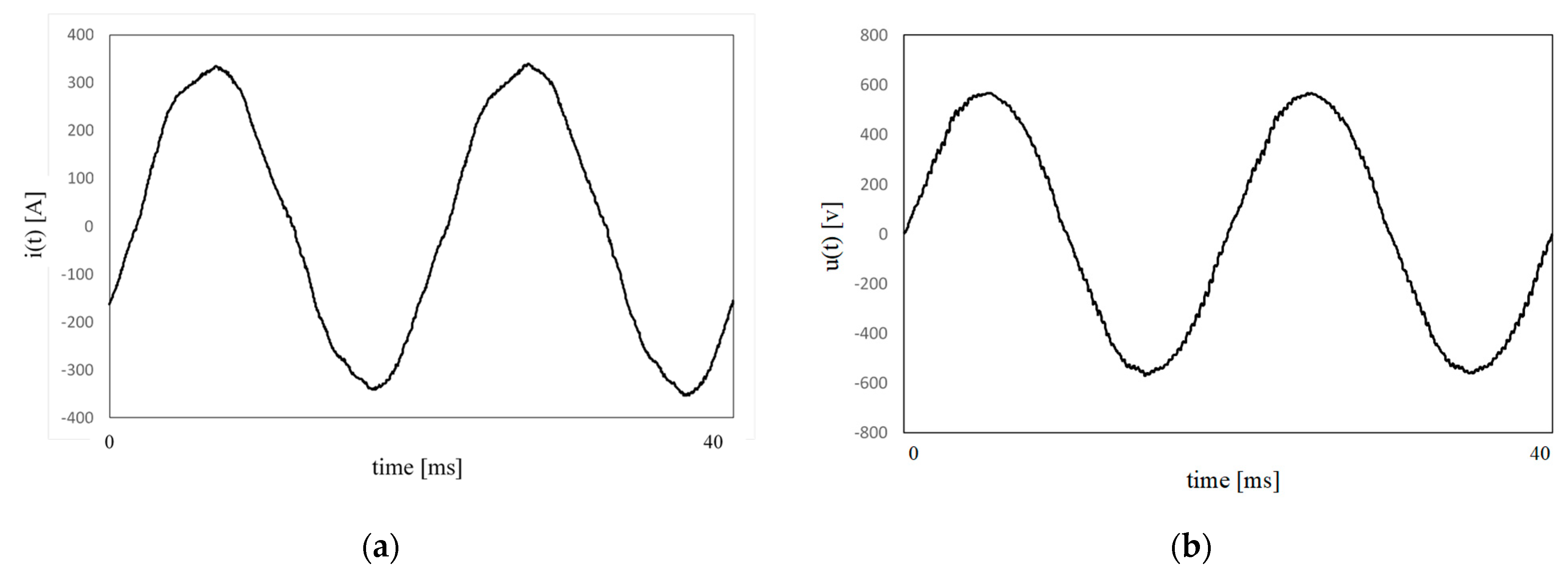
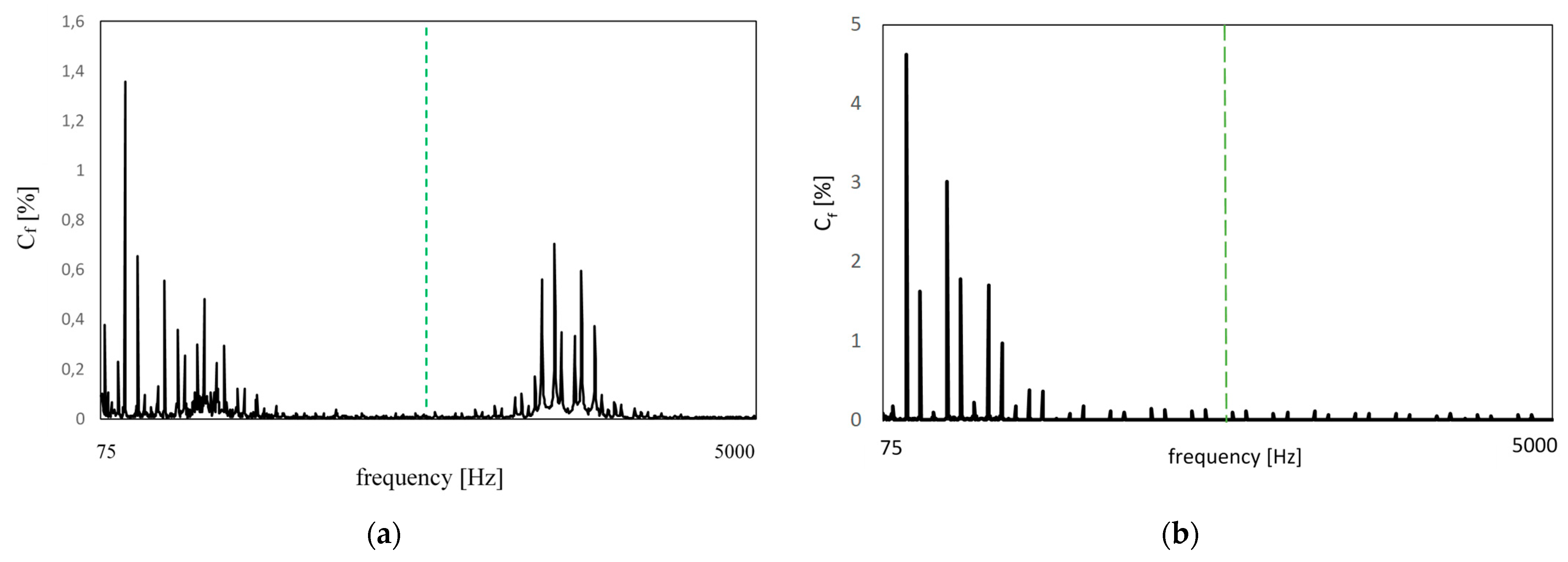
The calculation of THD should cover all harmonics up to the 50th order [7]. Two main drawbacks of this formula are that it covers only harmonics, and the frequency band is not determined or is insufficient for systems with active PWM front-end drives. The topology of such a drive is presented in Figure 1. The authors’ original research concerning such a system is presented in Figure 2 (voltage and current waveforms) and Figure 3 (voltage spectrum). The example was registered on-board of DP ship with electrical propulsion. During the research two generators worked in parallel with rated power of 425 kVA and 200 kVA. Rated voltage was equal to 400 V and rated frequency 50 Hz. The two AFE PWM drives with the rate power of 300 kW were used for the ship propulsion but the actual load was equal to 90 kW for each drive (sea going with reduced speed—half ahead). What is important, the switching frequency of each drive was equal to 3.6 kHz. This results in the distortions in the frequency band around the switching frequency, which is clearly visible in Figure 3a. For comparison reason the voltage spectrum registered during harbour manoeuvring of ship with drive containing 6-pulse rectifier was shown (bow thruster with rated frequency of 125 kW) in Figure 3b. The generator with rated power of 376 KVA worked during the registration. For both ships the computer with DAQ board was used. The sampling frequency was 30 kHz and cut-off frequency of anti-aliasing filter was set to 10 kHz.
As seen in Figure 3, the operation of the input IGBT input bridge rectifier significantly reduces the waveform distortions of conventional AC PWM drives with 6-pulse diode bridges or 12-pulse bridges. However, it can also introduce significant high-order distortions, above the 50th order. The voltage THD calculated for the example in Figure 2a and Figure 3 is equal to 1.86%, and it does not cover the visible distortions above 50th-order harmonics. Unfortunately, most of the available harmonic-monitoring devices cover this frequency band. However, extending the typical THD definition to 100th-order harmonics, as recommended by [33], is not a solution, as the calculated THD increases up to merely 1.88%, whereas the actual level of distortions reaches 2.65% combining both: harmonics and interharmonics (Equation (2)). Therefore, the authors have proposed [49] a more traditional definition of the distortion factor as the ratio of the RMS value of the residue, after elimination of the fundamental, to the RMS value of the fundamental component, expressed as a percentage. This is directly related to the concept of distortion factor introduced in the last century [50]. Some authors proposed to designate such a distortion factor as total waveform distortion (TWD) [51]. The definition is expressed as follows:
T W D n = V r m s 2 V 1 2 V 1 · 100
where: Vrms is voltage RMS value, V1 is voltage fundamental component RMS value.
This Equation (2) assumes values equal to or greater than THD defined by (1). Therefore, a comparison of the results of the calculation by both formulae enable a rough assessment of the interharmonics or components above the assumed harmonic frequency range. Further, detailed analysis can be carried out by the following formula (version for systems with a rated frequency equal to 50 Hz).
T W D 2.5 10 kHz = V r m s 2.5 10 kHz V 1 · 100
where: Vrms-2.5–10 kHz is RMS value of combined voltage component in the frequency range from 2.5 kHz up to 10 kHz, V1 is voltage fundamental component RMS value.
In fact the factor is similar like TWD described by Equation (2), but narrower frequency band. This can be defined as ratio of RMS value of components in the frequency band above harmonic frequency range up to 10 kHz and RMS value of fundamental component expressed in percentage. The interpretation is similar like in the case of THD, which combines harmonics in harmonic frequency range. The TWD2.5–10 kHz combines components above the harmonic frequency range, and this can be considered as combined distortions in sub-bands of 200 Hz like proposed in IEC 61000-4-7 [52]. The new factor enables rough identification of frequency band affected by distortions and provide additional information for diagnosis and troubleshooting.
However, analysis of all the above distortion factors may be insufficient for this case analysis. This concerns the waveforms with low-level interharmonics, but which are still above the threshold values of 0.1–0.2% suggested in Subsection 4.1. As such, it is advisable to measure the total interharmonic distortion factor (TIHD), defined as follows:
T I H D n = i h = 1.5 n V i h 2 V 1 · 100
where: Vih is the RMS value of the interharmonic subgroup, V1 is voltage fundamental component RMS value.
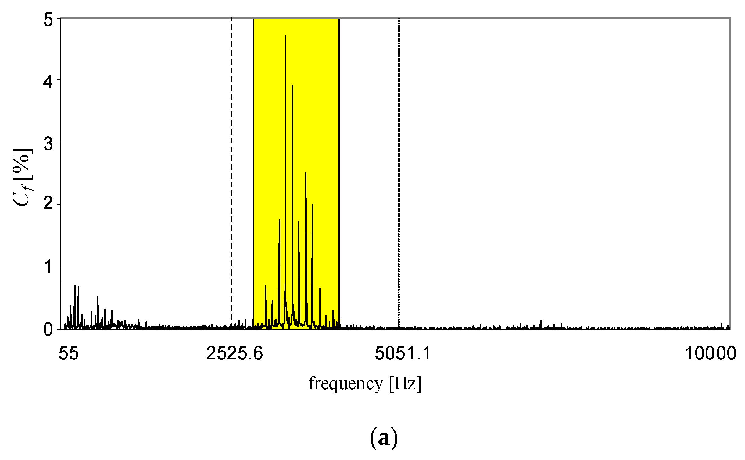
The interharmonic subgroup is defined in the IEC 61000-4-7 standard [52], as the square root of the sum square of the RMS values of the interharmonic frequency bins. For example, the spectrum of the original voltage registered at the navigation equipment terminal on-board a ship with AFE PWM drives is shown in Figure 4. This was registered on-board of above mentioned DP ship. The only difference is place (230 V 50 Hz system and time (before propulsion converters replacement).
In the presented case, the components above the 50th harmonic were dominant. This effect was due to poor design of the system and the choice of low-cost drives. The distortions are caused by the operation of the AFE power converters with a declared switching frequency of 3.6 kHz. Therefore, an appropriate analysis of this case requires covering the frequencies above the 50th harmonic, including interharmonics. The authors calculated the above proposed distortion indices, and the results are in Table 3.
Proper assessment of this case requires determining at least the following combination of the distortion factors:
  • TWD up to the 100th harmonic frequency range or 10 kHz, TWD2.5–10 kHz, TIHD up to the 50th harmonic frequency range;
  • THD up to 50th harmonic frequency range, TWD2.5–10 kHz, TIHD up to the 50th harmonic frequency range.
The above proposal is a necessary minimum for properly assessing waveform distortions at maritime microgrids. For an extension of the diagnosis capabilities, detailed information about harmonic subgroups and interharmonic subgroups should be provided. Moreover, the frequency range from the 50th harmonic to 10 kHz can be divided into subranges (e.g., 200-Hz wide, as proposed in the IEC 6100-4-7 standard [52]). Unfortunately, appropriate measuring devices do not exist; however, the authors have constructed a prototype device [53,54], which, after a minor software update, will be able to perform the task in real time.

4.3. Transient Disturbances

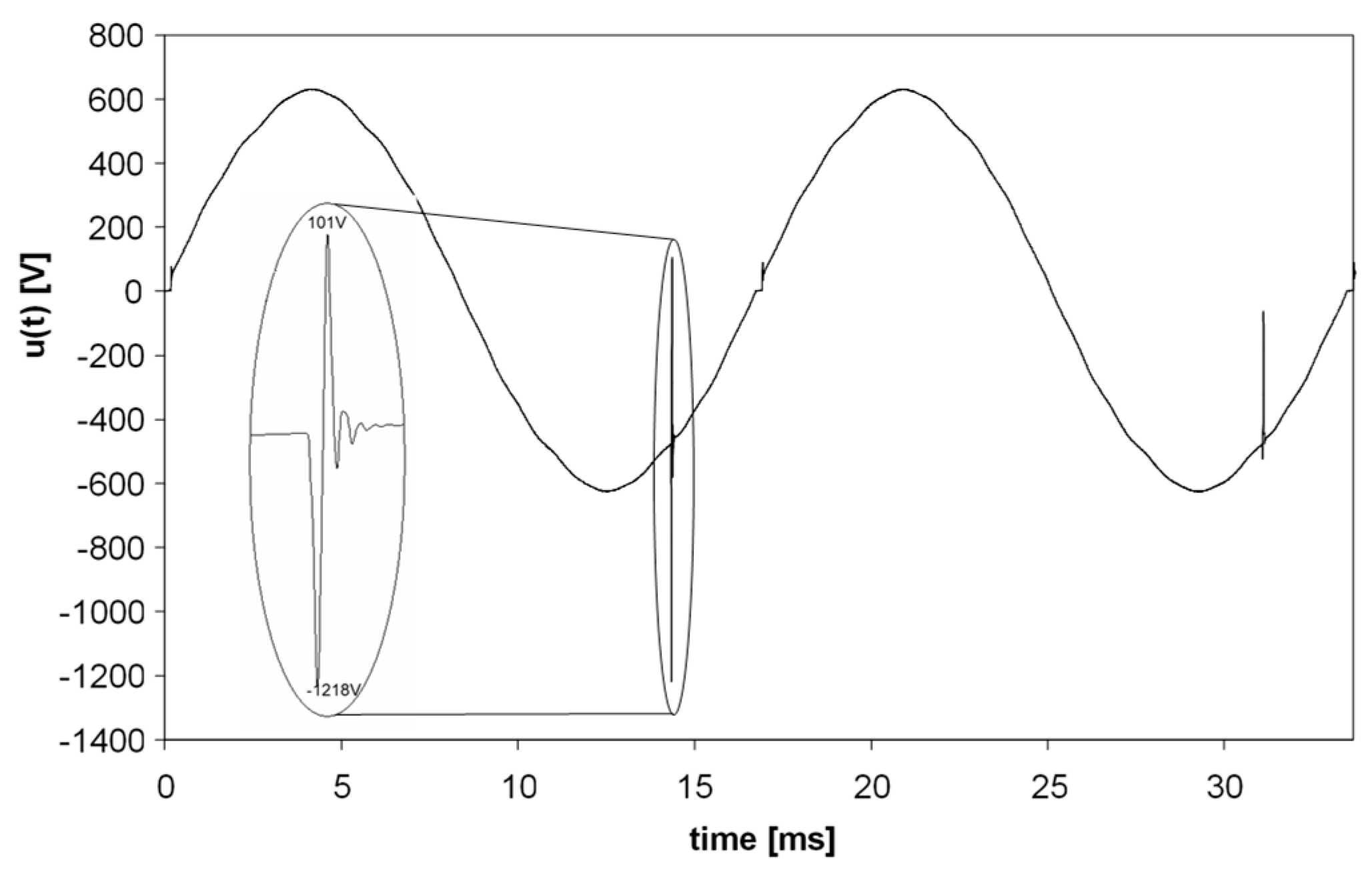
According to a Marine Accident Investigation Branch report [22], ‘Monitoring equipment should be capable of detecting transient voltage spikes’. Unfortunately, this recommendation was not included in the Unified Requirements of IACS, as only the requirement for continuously monitoring the THD factor was introduced [15], despite voltage spikes also being present in maritime microgrids. The occurrence of these spikes on shipboards is related to switching generators, harmonic filters and large receivers on and off as well as malfunctioning power-electronic equipment. The consequences of these spikes can be dangerous for ships, crew and the environment. For instance, the possible reason for the harmonic filter failure aboard Queen Mary II was ‘being exposed to frequent voltage transients due to increased number of switching cycles’ [22]. A similar situation was observed aboard a chemical tanker; due to a malfunction in the automatic voltage regulator (AVR), the random transient was observed during idle run of the generator with rated power of 1062 kVA, an example of which is shown in Figure 5. The rated voltage was equal to 440 V and rated frequency to 60 Hz. The voltage waveform was registered with sampling frequency equal to 150,375 Hz in the frequency band up to 50 kHz (cut-off frequency of anti-aliasing filter). It must be stressed that the phenomena are usually hard to capture and determining their magnitude strongly depends on frequency bandwidth of registering device.
The transient shown in Figure 5 also led to a failure of the capacitor in the generator AVR. Figure 5 also indicates the main problems with continuously monitoring such a phenomenon. These are related to their random nature, short duration, high amplitudes, and high frequencies. According to the IEEE 1159 standard [56], the transients are categorised as conducted high-frequency phenomena and can be divided into impulsive and oscillatory transients. The duration can be even below 50 ns, and frequencies above a few MHz. Typical magnitude can reach 4–8 p.u. [56]. Thus, ordinary power system performance-monitoring instruments are not appropriate for detecting and evaluating transient spikes.
Next, there are no commonly accepted indices for evaluating these phenomena. Nevertheless, some popular methods are listed in IEC Standard 61000-4-30 [2]. The most common are peak value, the rate of rise of the leading edge, frequency parameters, duration, the frequency of occurrence and energy. Hitherto, the standards related to maritime microgrids rarely deal with transient spikes. One exception is IEEE Standard 45.1-2017 [32], which states that voltage spikes should be below ±2500 V for 380–600 V systems. Unfortunately, the required minimal frequency band for transient detection was not proposed, which is vital for the results of the voltage spike magnitude measurement. For instance, the result of a magnitude measurement of the transient spike presented in Figure 5 increases linearly with an increase of the upper limit of the input frequency band of the measuring instrument [55].
The next problem concerns methods for detecting transients, for which there are many solutions. These are based on original signals or the extracted transient. The IEC 61000-4-30 lists the most common (e.g., based on absolute instantaneous value, envelope analysis after removing fundamental component, the sliding window method based on a comparison of instantaneous values with corresponding values of previous cycles or dv/dt method, etc. [2]). The authors have conducted research on the methods of transient detection in maritime microgrids. Finally, a simple solution based on a wavelet transform combined with absolute-value analysis and the dv/dt method was proposed [55]. The method consists of preliminary wavelet decomposition and partial synthesis and subsequent implementation of the following formula (5):
(|sksk−1)| > tr1 ∪ |sk|) > tr2
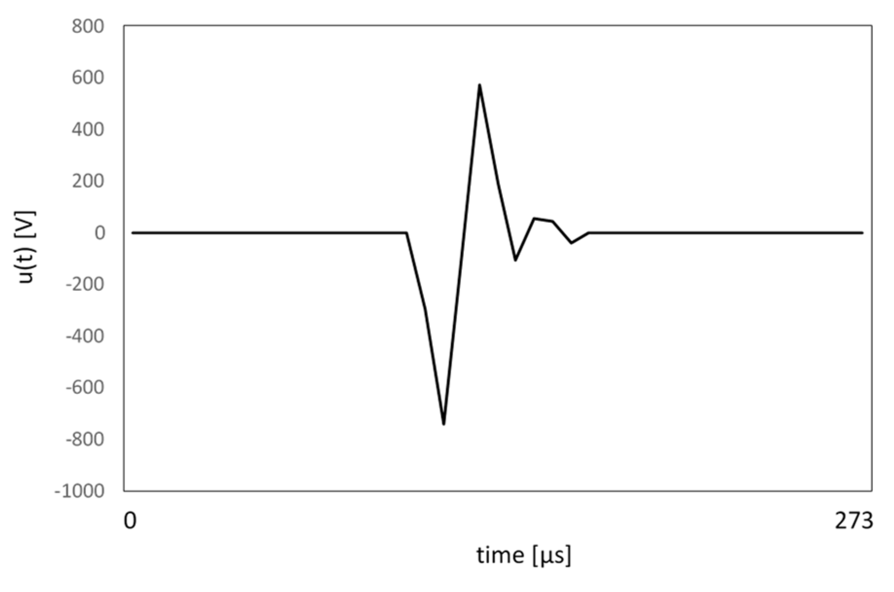
where the sk is an instantaneous sample of the extracted transient signal, sk−1 is the previous sample and tr1 and tr2 are threshold values. If condition (5) has the logical value ‘true’, then an impulse occurs. The simplicity of the formula allows fast, real-time transient detection, in fact starting and ending points of spike. This is the necessary condition for determining a number of transient spike indices, e.g., duration, energy. The threshold values tr1 and tr2 were chosen after experimental investigation in maritime microgrids, as tr1 = 0.2Vn and tr2 = 0.06Vn, where Vn is the nominal voltage amplitude [56]. The results of the application of the proposed solution for the transient depicted in Figure 5 is graphically presented in Figure 6.
The proposed solution enables fast transient detection and determination of its duration. Next, the proper transient indices can be determined on the basis of instantaneous values sk. This can be easily implemented in measuring instruments designed for power quality online monitoring. However, some precautions characteristic of the input channel of the measuring device, such as the sampling frequency and utilising an analog-to-digital converter input range, must be considered. The authors have constructed such a device, called an estimator-analyser of power quality, which is capable of measuring typical power quality indices in the frequency band up to 9 kHz, and online monitoring of voltage spikes in the frequency band up to 60 kHz [55]. For each detected transient, three indices are determined: voltage peak-to-peak value, duration, and energy. This method of detecting transients enables easy extension of the measuring device functions to add more transient parameters, including absolute peak values (with fundamental), rate of rise, and duration above predefined threshold values.
In summary, it is necessary to amend the Unified Requirements of IACS to include the requirement of the detection of transient spikes concurrently with measuring the THD factor. However, more research is yet to be done, namely, the requirements for the minimal frequency band of monitoring devices should be introduced, and threshold values for the proposed indices should be determined. This will require analysing typical voltage transient spikes in maritime microgrids as well as the susceptibility of installed equipment to detect both singular and accumulated, long-lasting spikes.

5. Discussion and Conclusions

The present regulations of ship classification societies do not provide sufficient protection of on-board equipment against malfunction due to excessive power quality disturbances. Considering numerous power quality-related ship accidents, the modification of rules of ship classification societies is proposed. The modifications concern determination of power quality indices for the assessment of voltage waveform distortions, as well as admissible levels of voltage subharmonics and interharmonics.
The presented case study and related discussion show (Section 4.2, Table 3) that implementation of IACS E24 rules encountered some difficulties, resulting from, among others, a lack of unification of power quality indices and measurement procedures in accordance with keeping the effective and comparable criteria for monitoring of harmonic distortion levels.
Additionally, the IACS E24 document and other maritime power quality standards and regulations do not cover all disturbances expected in a ship power system or are imprecise in basic parameter definitions at best. This concerns mainly the voltage distortion disturbances, such as interharmonics and transient spikes. There is a lack of proper indices for their assessment and established limit values. Moreover there are even doubts about precise definitions of such a basic factor like the THD coefficient.
Bearing in mind the aforementioned state-of-the-art, the authors decided to concentrate on the main problem resulting from technology development and wide usage of power electronic devices on the shipboard, and present their proposals concerning harmonics and interharmonics (Section 4.1), distortion indices (Section 4.2), and transient disturbances (Section 4.3). The main conclusions concerning the authors’ proposals and future works in the discussed power quality-related matter may be formulated as follows: because of extraordinary harmfulness of voltage SI, limitations concerning these power quality disturbances should be introduced to the rules of ship classification societies. At the same time the investigations on the impact of SI on electrical equipment are still incomplete and for the reason determination of the target SI limitations may last for comparatively long time. Nevertheless, because of the safety when afloat, the temporary admissible limits of SI could be established, at least for the SI of the frequency less than the doubled mains frequency. Considering the considerations presented in Section 4.2, as well as the previous proposals [44,49], the most appropriate temporary limit is 0.1% for any SI (or their sub-group) of the frequency less than the doubled fundamental one.
Careful analysis of results laid in Table 3 (Section 4.2) leads to the conclusion that proper assessment of the discussed case requires determining at least following combination of the distortion factors:
  • TWD up to 100th harmonic frequency range or 10 kHz, TWD2.5–10 kHz, TIHD up to 50th harmonic frequency range;
  • THD up to 50th harmonic frequency range, TWD2.5–10 kHz, TIHD up to 50th harmonic frequency range.
The above presented detailed proposal can be considered as the necessary minimum for proper assessment of waveform distortions at maritime microgrids. For extension of diagnosis capabilities, more detailed information about harmonic subgroups and interharmonic subgroups should be provided. Moreover, the frequency range from the 50th harmonic to 10 kHz can be divided into subranges, e.g., 200 Hz wide as proposed in IEC 6100-4-7 standard [52]. Unfortunately, the measuring devices with required functionalities do not exist on the market. The construction of the desired power quality monitoring device for maritime microgrids is necessary and will be easy. The authors have constructed a prototype of an appropriate device [53,54], which, after a minor software update, will be able to perform the task in real time.
With regard to transient disturbances analysis (Subsection 4.3), it seems of utmost necessity to amend the Unified Requirements of IACS and include the requirement of detection of transient spikes concurrently with measurement THD factor. However some research is yet to be done. Namely, the requirements for the minimal frequency band of monitoring devices should be introduced and threshold values for the above proposed indices should be determined. This will require the analysis of typical voltage transient spike characteristics in maritime microgrids and analysis of installed equipment susceptibility for the phenomena, both singular spike as well as accumulated effect of long lasting spikes.
It is worth emphasising that all of the highlighted power quality issues can be resolved and/or prevented if the correct and comprehensive technical guidance is obtained. Specialist marine power quality consultants and experts can assist ship owners, designers, shipbuilders, surveyors, and crew members in these matters, but this must go hand-in-hand with a comprehensive upgrade of marine classification society rules.

Author Contributions

Conceptualization, J.M.; formal analysis, T.T.; investigation, J.M., T.T., and P.G.; writing—original draft preparation, J.M., T.T., and P.G.; writing—review and editing, J.M., T.T., and P.G. All authors have read and agreed to the published version of the manuscript.

Funding

This research received no external funding.

Institutional Review Board Statement

Not applicable.

Informed Consent Statement

Not applicable.

Data Availability Statement

Not applicable.

Acknowledgments

We appreciate Marcin Miotk from the classification society DNV for his consultancy in this study. We are also grateful to DNV for providing us with company procedures for implementing the updated IACS rules and requirements.

Conflicts of Interest

The authors declare no conflict of interest.

References

  1. Mindykowski, J.; Tarasiuk, T. Problems of power quality in the wake of ship technology development. Ocean. Eng. 2015, 107, 108–117. [Google Scholar] [CrossRef]
  2. Electromagnetic Compatibility (EMC)—Part 4–30: Testing and Measurement Techniques—Power Quality Measurement Methods; IEC: Geneva, Switzerland, 2015.
  3. Electrical Installations in Ships—Part 101: Definitions and General Requirements; IEC: Geneva, Switzerland, 2018; Standard 60092-101.
  4. Requirements Concerning Electrical and Electronic Installations; International Association of Classification Societies IACS Req.: Hamburg, Germany, 2019.
  5. Part 4 Vessel systems and machinery. In Rules for Building and Classing Steel Vessels; American Bureau of Shipping ABS: Houston, TX, USA, 2019.
  6. Rules for Classification: Ships. Part 4 Systems and Components. Chapter 8 Electrical Installations; July 2019 ed., Amended October 2019; DNV GL: Høvik, Norway, 2019.
  7. Rules and Regulations for the Classification of Ships; Lloyd’s Register of Shipping: London, UK, 2019.
  8. Kumar, D.; Zare, F. Comprehensive review of maritime microgrids: System architectures, energy efficiency, power—Quality and regulations. IEEE Access 2019, 7, 1–11. [Google Scholar] [CrossRef]
  9. Mindykowski, J. Contemporary challenges to power quality in ship systems—metrological perspective. In Proceedings of the 22nd IMEKO TC4 International Symposium 20th, International Workshop on ADC Modelling and Testing, Iasi, Romania, 14–15 September 2017; pp. 536–558. [Google Scholar]
  10. Tarasiuk, T. Angular frequency variations at microgrids and its impact on measuring instrument performance. IET Gener. Transm. Distrib. 2016, 10, 3234–3240. [Google Scholar] [CrossRef]
  11. Gnaciński, P.; Tarasiuk, T.; Mindykowski, J.; Pepliński, M.; Górniak, M.; Hallmann, D.; Piłat, A. Power quality and energy Efficient operation of marine induction motors. IEEE Access 2020, 8, 152193–152203. [Google Scholar] [CrossRef]
  12. Tarasiuk, T.; Zunino, Y.; Bruno-Lopez, M.; Silvestro, F.; Piłat, A.; Molinas, M. Frequency fluctuations in marine microgrids: Origins and identification tools. IEEE Electrif. Mag. 2020, 8, 40–46. [Google Scholar] [CrossRef]
  13. Tarasiuk, T.; Górniak, M. Load sharing in ship microgrids under nonsinusoidal conditions—Case study. IEEE Trans. Energy Convers. 2017, 32, 810–819. [Google Scholar] [CrossRef]
  14. Tarasiuk, T.; Górniak, M.; Liu, W.; Savagheli, M.; Vasquez, J.C.; Chun-Lien, S.; Guerrero, J.M. Power quality assessment in shipboard microgrids under unbalanced and harmonic AC bus voltage. IEEE Trans. Ind. Appl. 2019, 55, 765–775. [Google Scholar]
  15. Mindykowski, J. Case study—Based overview of some contemporary challenges to power quality in ship systems. Inventions 2016, 1, 12. [Google Scholar] [CrossRef] [Green Version]
  16. Requirements Concerning Electrical and Electronic Installations, Harmonic Distortions for Ship Electrical Distribution System Including Harmonic Filters; June 2016, Rev.1 December 2018; International Association of Classification Societies, IACS UR E24: Hamburg, Germany, 2018.
  17. Mindykowski, J. Impact of staff competences on power quality—Related ship accidents. In Proceedings of the 2018 International Conference and Exposition on Electrical and Power Engineering, Iasi, Romania, 1–6 October 2018. [Google Scholar]
  18. Łozowicka, D.; Kaup, M. Analysis of the cause and effect of passenger ship accidents in the Baltic Sea. Sci. J. Marit. Univ. Szczec. 2015, 44, 68–73. [Google Scholar]
  19. Ugurlu, O.; Yildiz, S.; Loughney, S.; Wang, J. Modified human factor analysis and classification system for passenger vessel accidents (HFACS-PV). Ocean. Eng. 2018, 161, 47–61. [Google Scholar] [CrossRef] [Green Version]
  20. Mazaheri, A.; Montewka, J.; Nisula, J.; Kujala, P. Usability of accident and incident reports for evidence–based risk modelling—A case study on ship grounding reports. Saf. Sci. 2015, 76, 202–221. [Google Scholar] [CrossRef]
  21. Chavin, C.; Lardiane, S.; Morel, G.; Clostermann, J.; Langard, B. Human and organizational factors in maritime accidents: Analysis of collisions at sea using the HFACS. Accid. Anal. Prev. 2013, 59, 26–37. [Google Scholar] [CrossRef]
  22. Marine Accident Investigation Branch. Report of the Investigation of the Catastrophic Failure of a Capacitor in the Aft Harmonic Filter Room on Board RMS Queen Mary 2 While Approaching Barcelona on 23 September 2010; Marine Accident Investigation Branch: Southampton, UK, December 2011. Available online: http://www.maib.gov.uk/publications/investigation_reports/2011/qm2.cfm (accessed on 31 March 2021).
  23. Transportation Safety Board of Canada. Marine Investigation Report MO2W0135 Switchboard Fire, Passenger Vessel “Statendam”, Strait of Georgia, British Columbia 04 August 2002; Transportation Safety Board, Minister of Public Works Government Services: Canada, 2005; Available online: https://tsb.gc.ca/eng/rapports-reports/marine/2002/m02w0135/m02w0135.pdf (accessed on 31 March 2021).
  24. Fire alert on North Sea Platform; Website Publication: Sumburgh, Scotland, 2006; Available online: http://news.bbc.co.uk/2/hi/uk_news/scotland/4811538.stm (accessed on 31 March 2021).
  25. Evans, I.C. The perils of offshore power quality. Offshore Eng. 2014, 56–59. Available online: https://www.oedigital.com/news/444795-the-perils-of-offshore-power-quality (accessed on 24 May 2021).
  26. Zhang, W.; Yan, X.; Zhang, D.; Zhang, J. Evaluating the probability of power loss in ship electric propulsion system based on Bayesian belief networks. Mar. Technol. Soc. J. 2019, 53, 1–17. [Google Scholar] [CrossRef]
  27. Maritime and Coastguard Agency; Draft Marine Guidance Note (MGN). Potential Hazards of Excessive Harmonic Distortion of Current and Voltage of Onboard Electrical Systems; Maritime and Coastguard Agency: Southampton, UK, 2010. [Google Scholar]
  28. International Maritime Organization. IMO International Convention on Standards of Training, Certification and Watchkeeping for Seafarers, including Manila Amendments, STCW Convention and STCW Code; International Maritime Organization: London, UK, 2011. [Google Scholar]
  29. Evans, I.C. High frequency harmonics and marine power quality. Mot. Ship 2019, 1–5. Available online: https://www.motorship.com/news101/industry-news/high-frequency-harmonics-and-marine-power-quality (accessed on 24 May 2021).
  30. Evans, I.C. The future is electric—Let us safeguard it. Mot. Ship 2020, 1–5. Available online: https://www.motorship.com/news101/monitoring,-control-and-digitalization/the-future-is-electric-let-us-safeguard-it (accessed on 24 May 2021).
  31. Mindykowski, J. Towards safety improvement: Implementation and assessment of new standards of competence for electro-technical officers on ships. Marit. Policy Manag. 2017, 44, 336–357. [Google Scholar] [CrossRef]
  32. IEEE Recommended Practice for Electrical Installations on Shipboard-Design; IEEE: Piscataway, NJ, USA, 2017; p. 45.1.
  33. Testa, A.; Akram, M.F.; Burch, R.; Carpinelli, G.; Chang, G.; Dinavahi, V.; Hatziadoniu, C.; Grady, W.M.; Gunther, E.; Halpin, M.; et al. Interharmonics: Theory and modeling. IEEE Trans. Power Deliv. 2007, 22, 2335–2348. [Google Scholar] [CrossRef]
  34. Nassif, A.B. Assessing the impact of harmonics and interharmonics of top and mudpump variable frequency drives in drilling rigs. IEEE Trans. Ind. Appl. 2019, 55, 5574–5583. [Google Scholar] [CrossRef]
  35. Arkkio, A.; Cederström, S.; Awan, H.A.A.; Saarakkala, S.E.; Holopainen, T.P. Additional losses of electrical machines under torsional vibration. IEEE Trans. Energy Convers. 2018, 33, 245–251. [Google Scholar] [CrossRef]
  36. Zhiyuan, M.; Xiong, M.W.; Le, L.; Zhong, X. Interharmonics analysis of a 7.5 kW air compressor motor. CIRED Open Access Proc. J. 2017, 2017, 738–741. [Google Scholar] [CrossRef] [Green Version]
  37. Guillen-Garcia, E.; Zorita-Lamadrid, A.L.; Duque-Perez, O.; Morales-Velazquez, L.; Osornio-Rios, R.A.; Romero-Troncoso, R.D.J. Power consumption analysis of electrical installations at healthcare facility. Energies 2017, 10, 64. [Google Scholar] [CrossRef] [Green Version]
  38. Hou, R.; Wu, J.; Song, H.; Qu, Y.; Xu, D. Applying directly modified RDFT method in active power filter for the power quality improvement of the weak power grid. Energies 2020, 13, 4884. [Google Scholar] [CrossRef]
  39. Feola, L.; Langella, R.; Testa, A. On the effects of unbalances, harmonics and interharmonics on PLL systems. IEEE Trans. Instrum. Meas. 2013, 62, 2399–2409. [Google Scholar] [CrossRef]
  40. Testa, A.; Langella, R. Power system subharmonics. In Proceedings of the IEEE Power Engineering Society General Meeting, San Francisco, CA, USA, 16 June 2005; Volume 3, pp. 2237–2242. [Google Scholar]
  41. Ghaseminezhad, M.; Doroudi, A.; Hosseinian, S.H.; Jalilian, A. An investigation of induction motor saturation under voltage fluctuation conditions. J. Magn. 2017, 22, 306–314. [Google Scholar] [CrossRef]
  42. Ghaseminezhad, M.; Doroudi, A.; Hosseinian, S.H.; Jalilian, A. Analysis of voltage fluctuation impact on induction motors by an innovative equivalent circuit considering the speed changes. IET Gener. Transm. Distrib. 2017, 11, 512–519. [Google Scholar] [CrossRef]
  43. Fuchs, E.F.; Roesler, D.J.; Masoum, M.A.S. Are harmonics recommendations according to IEEE and IEC too restrictive? IEEE Trans. Power Deliv. 2004, 19, 1775–1786. [Google Scholar] [CrossRef]
  44. Gnaciński, P.; Pepliński, M.; Murawski, L.; Szeleziński, A. Vibration of induction machine supplied with voltage containing subharmonics and interharmonics. IEEE Trans. Energy Convers. 2019, 34, 1928–1937. [Google Scholar] [CrossRef]
  45. Gnaciński, P.; Hallmann, D.; Klimczak, P.; Muc, A.; Pepliński, M. Effects of voltage interharmonics on cage induction motors. Energies 2021, 14, 1218. [Google Scholar] [CrossRef]
  46. Feese, T.; Ryan, M. Torsional vibration problem with motor/ID fan system due to PWM variable frequency drive. In Proceedings of the 37th Turbomachinery Symposium 2008, Texas A&M University, Turbomachinery Laboratories, TX, USA, 8–11 September 2008. [Google Scholar]
  47. Voltage Characteristics of Electricity Supplied by Public Distribution Network; EN Standard 50160: Brussels, Belgium, 2010.
  48. De Abreu, J.P.G.; Emanuel, A.E. The need to limit subharmonics injection. In Proceedings of the 9th International Conference on Harmonics and Quality of Power, Orlando, FL, USA, 1–4 October 2000; Volume 1, pp. 251–253. [Google Scholar]
  49. Tarasiuk, T.; Mindykowski, J. An extended interpretation of THD concept in the wake of ship electric power systems research. Measurement 2012, 45, 207–212. [Google Scholar] [CrossRef]
  50. Instruments and Measurements. Annual Report of Committee on Instruments and Measurements. Trans. Am. Inst. Electr. Eng. 1929, 48, 1385–1390. [Google Scholar] [CrossRef]
  51. Bollen, M.; Gu, I. Signal processing of power quality disturbances; Wiley-Interscience: Hoboken, NJ, USA, 2006. [Google Scholar]
  52. General Guide on Harmonics and Interharmonics Measurements for Power Supply Systems and Equipment Connected Thereto; IEC, Std.: Geneva, Switzerland, 2008; IEC 61000-4-7.
  53. Tarasiuk, T. Estimator-analyser of power quality: Part I—Methods and algorithms. Measurement 2011, 44, 238–247. [Google Scholar] [CrossRef]
  54. Tarasiuk, T.; Szweda, M.; Tarasiuk, M. Estimator-analyser of power quality: Part II—Hardware and research results. Measurement 2011, 44, 248–258. [Google Scholar] [CrossRef]
  55. Tarasiuk, T.; Szweda, M. DSP instrument for transient monitoring. Comput. Stand. Interfaces 2011, 33, 182–190. [Google Scholar] [CrossRef]
  56. Recommended Practice for Monitoring Electric Power Quality; IEEE 1159–2019 IEEE: Piscataway, NJ, USA, 1994.
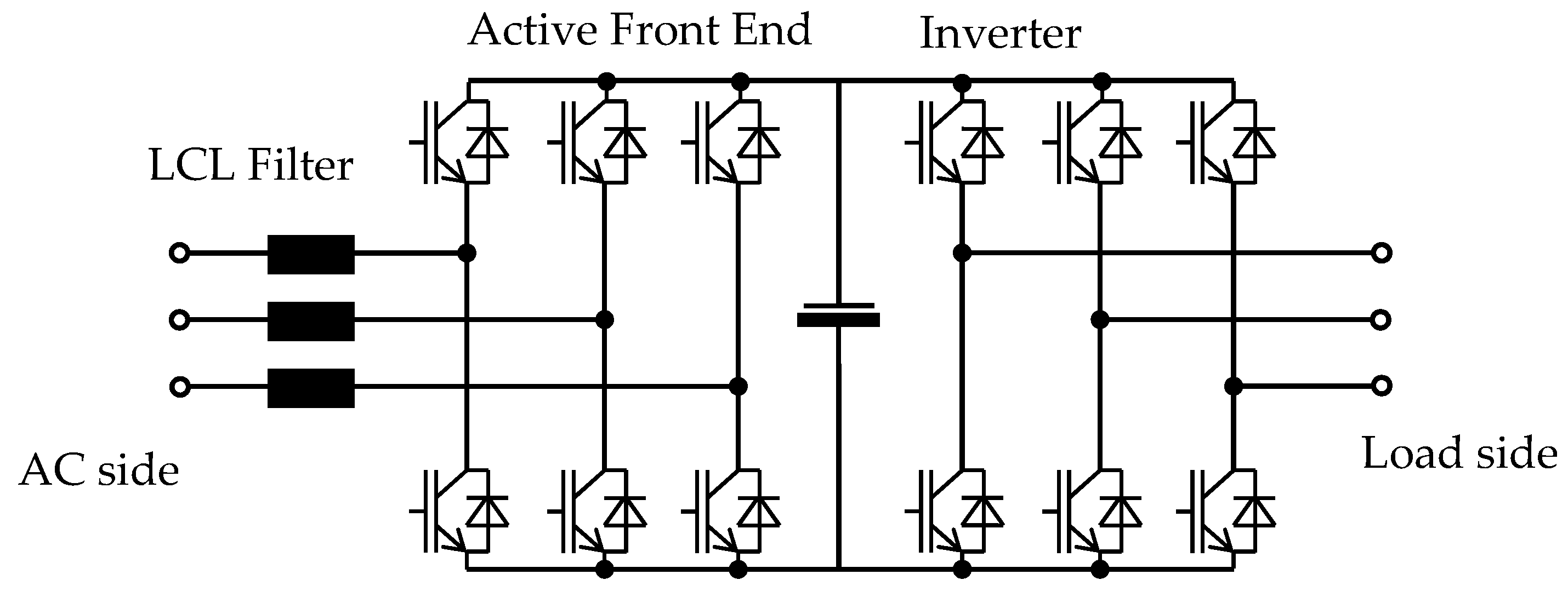
Figure 1. Application of an IGBT ‘Active Front End’ to an AC PWM drive.
Energies 14 03151 g001
Figure 2. ‘Active Front End’ input current and voltage waveforms at main bus bars.
Energies 14 03151 g002
Figure 3. Voltage spectra at main bus bars of the maritime systems with AC PWM drives with an ‘Active Front End’ (a) and at main bus bars of the maritime systems with 6-pulse diode bridge (b). Note the distortions above the 50th order, marked by the green dashed line. Cf is the content of higher frequency components in relation to fundamental voltage, both harmonics and interharmonics.
Energies 14 03151 g003
Figure 4. Exemplary waveform of supply voltage; (a) the analysed frequency sub-band is marked with yellow; the dashed line marks the frequency of the 50th harmonic whereas the dotted line marks the frequency of the 100th harmonic; (b) the extended frequency sub-band 2843.8–4157.1 Hz is marked with yellow; the dashed lines mark the harmonic frequencies as integer multiples of the fundamental frequency equal to 50.51 Hz [1]. Cf is the content of higher frequency components in relation to fundamental voltage, both: harmonics and interharmonics.
Energies 14 03151 g004aEnergies 14 03151 g004b
Figure 5. Example transient registered in a ship network [55].
Energies 14 03151 g005
Figure 6. Extracted transient using wavelet transform and formula (5).
Energies 14 03151 g006
Table 1. Analysis of select power quality accidents [17,22,23,24].
Case StudyType and Name of Ship, Year of the EventType of Ship Power PlantKind of AccidentAccident Reasons
DirectIndirect
1Passenger cruise liner, RMS Queen Mary 2, 2010 Energies 14 03151 i001Engine room of CODLAG (combined diesel electric and gas turbine), integrated electric propulsion; all-electric ship, 11 kV networkThe catastrophic failure of a capacitor in the aft harmonic filter room, and explosion in the aft main switchboard; temporary loss of vessel manoeuvrability The initial degradation of harmonic filter capacitor constructionA lack of continuous monitoring of electric power quality; shortcomings in ship tests, and operation
2Passenger ship, MS Statendam, 2002 Energies 14 03151 i002Diesel-electric-generation system cooperating with azipods/propulsion motors; All-electric ship, 6.6 kV networkArc-flash event in a main circuit breaker, and fire accident in the main switchboard roomDead short caused the failure of DG2 circuit breaker, causing an explosion and fire in the main switchboard roomA lack of analysis of damage symptoms; a lack of sufficient qualifications of marine engineers, including electricians on-board
3Oil platform, Tern Alpha, 2006 Energies 14 03151 i003Platform electrical distribution system is based on all-electrical ship system solution. Technical data concerning power generation module are not publicly availableExplosion in the gas compression module, fire, personnel evacuation, stopping of the drilling processOverheating of a high-voltage electrical motorHigh level of distortion in the platform electrical distribution system
Table 2. Implementation of the IACS UR E24 2016/2018 rules [5], based on a case study of DNV GL 2019 [6].
IACS UR E24 2016/2018 RulesDNV GL Rules for Ships, 2019
Place of DescriptionConsidered IssuePlace of DescriptionWay of Implementation
Section 1 Scope
To what kind of ship are the requirements of this UR applied?
Part 4, Chapter 8, Section 1, point 2.2Documentation related to system design shall be submitted when more than 20% of connected load is by semiconductor assemblies, in relation to connected generating capacity; also required where the electrical distribution system on board a ship includes harmonic filters. In such cases, the effects of a filter failure shall also be calculated. At the same time, in Part 4, Chapter 1, Section 2, point 1.2.8 (c), a related exclusion is placed. Harmonic filters integrated in frequency converters, or installed for single consumers, such as pump motors, may be excluded from these requirements.
Section 2General
The limit of the total harmonic distortion (THD) and possibilities of its relaxation
Part 4, Chapter 8, Section 2, point 1.2.7The DNV GL rules concerning the requirements connected with limit values and operation conditions of operating harmonic distortion as well as some recommendations concerning the relaxation conditions are included in Part 4, Chapter 1, Section 2, point 1.2.7:
‘1.2.7 Harmonic distortion
(a) Equipment producing transient voltage, frequency and current variations shall not cause malfunction of other equipment on board, neither by conduction, induction or radiation.
(b) In distribution systems the acceptance limits for voltage harmonic distortion shall correspond to IEC 61000-2-4 Class 2. In addition, no single order harmonic shall exceed 5%.
Guidance note: IEC 61000-2-4 Class 2 implies that the total voltage harmonic distortion shall not exceed 8%.’
Authors’ note: THD is a ratio of the RMS value of the sum of all the harmonic components up to the 50th order to the RMS value of the fundamental component.’
(c) The total harmonic distortion may exceed the values given in (b) under the condition that all consumers and distribution equipment subjected to the increased distortion level have been designed to withstand the actual levels. The system and components ability to withstand the actual levels shall be documented.
(d) When filters are used for limitation of harmonic distortion, special precautions shall be taken so that load shedding or tripping of consumers, or phase back of converters, do not cause transient voltages in the system in excess of the requirements in [1.2.4].
Guidance note: the following effects should be considered when designing for higher harmonic distortion, refer to (c):
- Additional heat losses in machines, transformers, coils of switchgear and controlgear;
- Additional heat losses in capacitors for example in compensated fluorescent lighting;
- Resonance effects in the network;
- Functioning of instruments and control systems subjected to the distortion;
- Distortion of the accuracy of measuring instruments and protective gear (relays);
-Interference of electronic equipment of all kinds, for example regulators, communication and control systems, position-finding systems, radar and navigation systems. A declaration or guarantee from system responsible may be an acceptable level of documentation.’
Section 3Monitoring of harmonic distortion levels for ships including harmonic filters
Subsection 3.1; for new ships, facilities to continuously monitor the levels of harmonic distortion experienced on the busbar as well as alerting the crew should this level exceed acceptable levels
Part 4, Chapter 8, Section 2, point 1.2.8Implementation of the related IACS UR concerning continuous power quality monitoring with alarm procedures is directly placed in Part 4, Chapter 1, Section 2, point 1.2.8 (b): ‘Where the electrical distribution system on board a ship includes harmonic filter units, the levels of harmonic distortion experienced on the main busbar shall be continuously monitored. Should the level of harmonic distortion exceed the acceptable limits, an alarm shall be given at a manned location. For ships with class notation E0, the alarm shall be logged.’
Subsection 3.2; for existing ships, as minimum harmonic distortion levels of main busbar are to be measured annually under seagoing conditions as close to the periodical machinery survey.Part 7, Chapter 1, Section 2, point 3.1.5Implementation of the related IACS UR concerning harmonic-distortion-levels control, together with measurement and their records conditions, in reference to existing ships, is in Part 7, Chapter 1, Section 2, point 3.1.5:
‘For electrical installations the survey shall include:
- Examination of main source of electrical power with respect to general condition, fire hazard and
personnel safety, i.e., generators, main switchboards, distribution boards, control gear, consumers,
chargers, and battery/UPS systems.
- For all E0, AUT, or AUT-nh vessels (built at any time) and all vessels constructed on or after 1 July, 1998
where electricity is necessary for propulsion and steering, test of automatic start and connection to the switchboard of the standby generator set, shall be carried out.
- Where the electrical distribution system on board a ship includes harmonic filters (with exception of pumps’ prime movers):
- Harmonic distortion levels of main busbar on board such existing ships shall to be measured annually under seagoing conditions as close to the periodical machinery survey as feasible. Records of all the above measurements shall to be made available to the surveyor.
Each measurement shall be taken at maximum distortion levels and identical conditions.
Guidance note:
This requirement applies for ships contracted for construction before 1 July 2017.’
Section 4Mitigation of the effects of harmonic filter failure on a ship’s operation. The system integrator of the distribution system with harmonic filters is to show, by calculation, the effect of a failure of a harmonic filter on the level of harmonic distortion experienced. The system integrator of the distribution system is to provide the ship owner with guidance documenting permitted modes of electrical distribution system, while maintaining harmonic distortion within acceptable limits during different operation conditions of the system for any combination of harmonic filters. The calculation results and validity of the guidance provided are to be verified by the surveyor during sea trials.Part 8, Chapter 8, Section 2, point 1.2.8 and point 3.1.3Implementation for the related Section of IACS UR is in Part 4, Chapter 1, Section 2, point 1.2.8 (a):
‘Passive and active harmonic filter assemblies/units:
(a) Where the electrical distribution system on board a ship includes harmonic filter units, the system integrator of the distribution system shall show, by calculation, the effect of a failure of a harmonic filter unit on the level of harmonic distortion experienced. The system integrator of the distribution system shall provide the ship owner with guidance documenting permitted modes of operation of the electrical distribution system while maintaining harmonic distortion levels within acceptable limits. The system integrator shall also calculate the harmonic distortion that will be experienced in case of a failure of a harmonic filter, and provide guidance on mitigating actions as operating modes or reduced power levels’
This information is also in point 3.1.3:
‘Harmonic distortion
(a) All equipment shall be constructed to operate at any load up to the rated load, with a supply voltage containing harmonic distortion as given in Section 2, point 1.2.7.’
Section 5Protection arrangements for harmonic filters.
Arrangements are to be provided to alert the crew in the event of activation of the protection of a harmonic-filter circuit. The constructional contains as a three-phase unit with individual protection of each phase, as well as the conditions concerning a current unbalance detection system independent of the overcurrent protection alerting the crew.
The references in the DNV GL rules to comply with the related Section 5 of the IACS UR are included in the Chapters 8 and 1, of Parts 4 and 7, respectively. Additionally, the DNV GL rules for ships in some places are cited by the guidance note ‘See IACS UR E24′, and this indicates planned accordance of both documents.
Table 3. Distortion indices calculated for the example from Figure 4.
Distortion FactorValue
THD (up to the 50th harmonic)1.39%
THD (up to the 100th harmonic)1.61%
TWD (up to the 100th harmonic frequency range)8.30%
TWD (up to 10 kHz)8.37%
TWD2.5–10 kHz8.22%
TIHD (up to the 50th harmonic frequency range)0.68%
TIHD (up to the 100th harmonic frequency range8.14%
Publisher’s Note: MDPI stays neutral with regard to jurisdictional claims in published maps and institutional affiliations.