Article

Axial Flux PM In-Wheel Motor for Electric Vehicles: 3D Multiphysics Analysis

1
Department of Industrial and Information Engineering and Economics, University of L’Aquila, Monteluco di Roio, 67100 L’Aquila, AQ, Italy
2
Spin Applicazioni Magnetiche Srl, Via F. Corselli n. 11, 29122 Piacenza, PC, Italy
*
Author to whom correspondence should be addressed.
Energies 2021, 14(8), 2107; https://doi.org/10.3390/en14082107
Submission received: 11 February 2021 / Revised: 24 March 2021 / Accepted: 5 April 2021 / Published: 9 April 2021

Abstract

:
The Axial Flux Permanent Magnet (AFPM) motor represents a valid alternative to the traditional radial flux motor due to its compact structure; it is suitable for in-wheel applications so that the transmission gear can be suppressed. The modeling of the motor is a purely Three-Dimensional (3D) problem and the use of 3D finite element tools allows the attainment of accurate results taking also into account the effects of the end-windings. Moreover, a 3D multiphysics analysis is essential to evaluate not only the motor performance and its thermal behavior, but also the electromagnetic forces acting on the surfaces of the stator teeth and of the magnets that face the air gap. Moreover, as the vehicle’s motors often work in variable-speed conditions, the prediction of vibrations and noise for electric motors over a wide speed range is usually necessary. The paper presents a double-sided AFPM motor for a small pure electric vehicle; the basic drive architecture includes four axial flux motors installed directly inside the vehicle’s wheels. The aim is to propose advanced and integrated electromagnetic, vibroacoustic and thermal analyses that allow the investigation of the axial flux motor behavior in a detailed and exhaustive way.

Graphical Abstract

1. Introduction

The electric mobility represents a possible solution to the pollution and global warming problems. The research on these topics is intense and there is a great interest in finding innovative and more efficient solutions for the main component of the powertrain: the electric motor. Nowadays, the types of electric motors for automotive applications that are most frequently adopted are radial flux machines, either squirrel cage induction or Permanent Magnet (PM) ones, but innovative motor typologies are being proposed and investigated to guarantee a high efficiency and high torque and power densities [1].
The current Electric Vehicles (EV) can be classified into two categories according to their configurations, namely “indirect-drive” and “direct-drive”.
The first solution needs the reduction gear and the differential gear and presents mechanical losses during the power transmission from the motor to the car’s tires.
On the other hand, the direct-drive electric vehicle is simpler because it does not require transmission components and allows to reduce the volume and the weight of the whole system while improving its efficiency [2,3]: it could be the future trend for the new EVs. For this specific application, the Axial Flux Permanent Magnet (AFPM) motor represents a valid alternative to the traditional radial flux motor due to its compact structure; it can also be suitable to be placed inside the wheel so that the transmission gear is suppressed [4,5,6]. In [7], a prototype of an AFPM motor has been realized, tested and compared to a radial flux motor.
Due to the integration of the reducer with the motor, the heat dissipation, lubrication, protection, and torque output capacity of the in-wheel motor system can be significantly improved.
In this paper, a small pure electric vehicle with gearless in-wheel motors was considered as a case study; the basic drive architecture is shown in Figure 1. The drive system includes four axial flux PM synchronous motors and four motor drive controllers, each of which is composed of a three-phase inverter. As the motor directly drives the wheel, the axial length of the motor itself must be small and its diameter could be relatively large; furthermore, the motor has to be designed as a high-torque low-speed motor.
The modeling of an axial flux machine is a pure 3D problem and the use of 3D Finite Element (FE) tools [8,9,10] allows the attainment of accurate results taking also into account the effects of the end-windings. Moreover, a 3D multiphysics analysis is essential to evaluate not only the motor performance, but also its thermal behavior and the electromagnetic forces acting on the surfaces of the stator teeth and of the magnets. Moreover, since the vehicle’s motors often work in variable-speed conditions, the prediction of vibrations and noise for electric motors over a wide speed range is usually necessary [11].
This paper is organized as follows: the design of the AFPM in-wheel motor is illustrated in Section 2 together with the criteria used for the choice of the number of poles and slots; then, a case study is proposed in Section 3. In Section 4, the multiphysics analysis is presented in order to predict the performance, the temperatures and the electromagnetic vibration and noise of the axial flux PM motor. Finally, the conclusions are drawn in Section 5.

2. The AFPM Motor Sizing Equations

The AFPM motors can be designed in single-sided or double-sided configurations and as single-stage or multi-stage machines [12,13,14]. In the case of a double-sided configuration (Figure 2), the motor has two rotor discs with surface Permanent Magnets (PMs) and a central stator core that is sandwiched between the rotor discs (Figure 2). The slotted stator core is manufactured from laminated electrical steel and has two sets of three-phase windings: Figure 3 shows the prototype of a laminated stator core. A low-cost process foresees the stator slot cutting; however, this process gives rise to the short-circuit of the lamination sheets and to a slight increase in the iron losses. To avoid this drawback, the “slinky technology” can be used: the lamination strip is carefully punched and then wound to realize the stator core.
The PMs are glued to the surfaces of the solid mild-steel rotor discs. The flux in the AFPM motor flows axially through the air gap.
The numbers of slots and poles have to be chosen so that their ratio is fractional and, using concentrated windings, it is possible to reduce the cogging torque and to improve the machine performance. The AFPM machine with fractional-slot concentrated windings [8], compared to the traditional distributed winding one, offers many advantages: shorter end-turns, reduced copper losses and a higher slot fill factor.
Several authors propose a criterion for the choice of the right N. poles-N. slots combination. In [5], the authors suggest to reduce the cogging torque using fractional-slot windings and magnetic wedges in the slots. Fractional-slot windings with a number of slots per pole and per phase less than unity sometimes become mandatory for the construction of low-power machines with a large number of pole pairs. A fractional-slot winding typically exhibits an inductance higher than the corresponding integer-slot winding configuration. In [6], the authors point out that the choice of a high number of rotor poles allows the reduction of the mass; however, the thickness of the magnetic air gap must be small compared to the pole pitch in order to reduce the leakage flux. In [4], the authors remark that the appropriate selection of the number of poles is important to realize a small-sized motor. A low number of poles would lead to the increase in the axial length since the size of each PM would have to be greater, resulting in a thicker rotor yoke; the radial size of the motor would also be greater and the leakage inductance and copper losses would increase. On the other hand, if the number of poles was high, the frequency would be higher and the iron losses would increase. In the AFPM motor, the pole width w p r and the pole pitch τ r are functions of the axial flux machine radius r :
τ r = 2 π   r 2 p = π   r p
and
β i = w p r τ r
where p is the number of pole pairs.
The linear current density is also a function of the radius and its peak value for a three-phase machine is equal to:
A m a x = 3 2   N t   I p h p   τ r = 3 2   N t   I p h π   r
where N t is the number of turns in series per phase and I p h is the phase current.
It is convenient to introduce the inner-to-outer PM diameter ratio:
k D = D i D o
The average electromagnetic torque for a three-phase double-sided machine is given by the following equation:
T = 2 π   B a v g   A r m s   R o 3   k D k D 3
where B a v g is the average value of the air gap flux density and A r m s is the rms value of the line current density.
In most axial flux machines, the k D   ratio is a major design parameter, which has significant effects on the characteristics of the machine and, therefore, must be carefully chosen; this aspect has been fully investigated in [15], where the k D value for high torque density AFPM motors should be in the range 0.4–0.5. The paper analyzes also the “ratio between the axial length and the outer diameter of the whole machine”, which represents how flat the motor is: when this ratio has a small value, the torque and the torque density of the AFPM motor will be higher.

3. A Case Study

The AFPM motor was designed for a small pure electric vehicle without reduction gears: the basic drive architecture includes four axial flux motors installed directly inside the vehicle’s wheels (Figure 1). The requirements of the AFPM motor are listed in Table 1. Due to the limited space inside the wheel, the AFPM motor should guarantee a high torque density; this goal has been achieved with a double-sided AFPM motor with a double air gap and whose stator core is sandwiched between two rotor plates.
The sizing procedure proposed in [12] has been adopted by means of a spreadsheet software. The first part of the design procedure consisted of the choice of the rotor pole and of the stator slot numbers: for this purpose, different combinations have been tested and the following solution has been adopted: 18 stator slots and 16 rotor poles, single layer, fractional slot and concentrated windings (alternate type).
The main motor data are shown in Table 2: Figure 4 illustrates the 3D geometries of the double-sided motor and Figure 5 shows the scheme of the concentrated winding, where half of the teeth are wound and there is one coil in each slot.
Regarding the materials, the AFK1 Iron-Cobalt (Fe-Co) alloy has been chosen for the stator core and for the rotor plates: it is generally the most expensive alloy (about 30 times the cost of the traditional Fe-Si electrical steel). If alloyed with iron, cobalt reaches the highest maximum saturation magnetization of all the materials. With a high maximum flux density, the size and the weight of electrical machine cores can be significantly decreased. This allows the design of electrical machines with very high power densities.
The chosen PMs are in Neodymium-Iron-Boron (NdFeB), with a remanent flux density Br at 20 °C of 1.16 T, a coercive field strength Hc of 900 kA/m, and thermal coefficients for Br and Hc of −0.11%/°C and −0.54%/°C, respectively.

4. The 3D Multiphysics Analysis

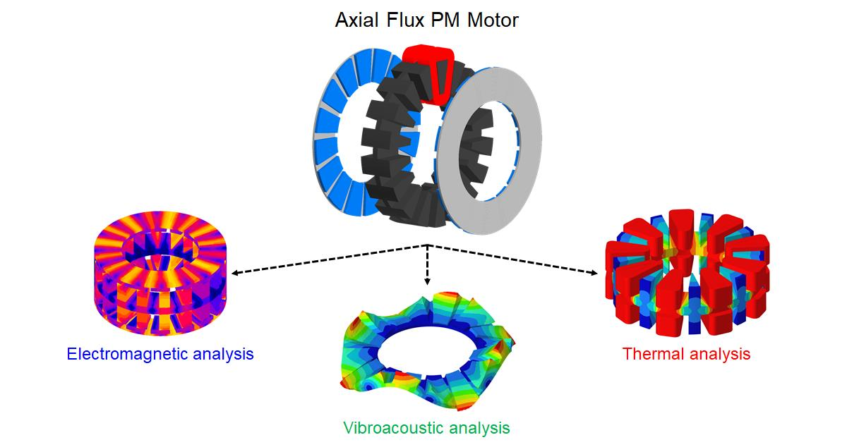
The components of the AFPM motor vary with its radius and this makes the analysis more complicated: thus, 3D FE analyses have been conducted through the Altair tools. Particularly, a 3D multiphysics analysis allowed the evaluation of not only the motor performance, but also the thermal behavior and the electromagnetic forces acting on the surfaces of the stator teeth and of the permanent magnets.

4.1. Electromagnetic Analyses

3D electromagnetic analyses have been carried out in order to evaluate the performance of the AFPM motor and its magnetic field distribution: static analyses have been performed to shorten the simulation time. A temperature of 100 °C has been imposed for both the stator windings and the permanent magnets.
Table 3 lists the motor performance at base speed and at maximum speed, and it fully satisfies the initial requirements with an efficiency higher than 80%.
The Back ElectroMotive Force (BEMF) at no-load is shown in Figure 6 and it exhibits a sinusoidal behavior, while Figure 7 presents the motor torque profile: the ripple, calculated as the ratio of the difference between the maximum and the minimum torque values to the average one, is very low and this is mainly due to the use of concentrated windings and to the right choice of the combination N. poles-N. slots.
The 3D on-load analysis allowed the evaluation of the flux density distributions (Figure 8) in the AFPM motor; the maximum values in the stator teeth and in the stator yoke are about 2.4 T and this value is reasonable thanks to the use of the Fe-Co electrical steel, which has a high saturation value.
The Torque-Speed curve is reported in Figure 9 and it points out a constant torque of about 78 Nm up to 840 rpm and a torque of about 68 Nm at maximum speed (1200 rpm).
Moreover, Table 4 shows the motor losses during its on-load operation at different working points: in this way, it is possible to evaluate the motor performance and efficiency for many speed points, which is important for traction applications. As it can be seen, the Joule losses remain the same since the current value is constant and the current control angle changes, hence changing the d-axis and q-axis current components; all the other losses increase together with the operating speed of the electric motor (i.e., the iron losses depend on the frequency value). Although, it can be noticed that the efficiency does not decrease in the flux-weakening region, making the motor meet the efficiency requirements for this kind of application.

4.2. Noise and Vibration Analyses

The NVH (Noise, Vibration and Harshness) analysis in the automotive field is necessary in order to evaluate the vehicle’s comfort and to make it comply with the environmental requirements, since the motor can be a great source of noise and vibrations if not properly designed and controlled [16]. The reason why the electric motor can produce noise has to be found in the magnetic forces acting between the stator teeth and the rotor permanent magnets [17,18].
Three main categories of vibrations and noise produced by an electrical machine can be defined: the electromagnetic vibrations and noise (due to higher harmonics of time and space, phase unbalance, magnetic saturation, slot openings, magnetostriction, etc.), the mechanical ones (due to bearings, rotor unbalance, shaft misalignment, etc.) and the aerodynamic ones (due to the air flow produced by the cooling fan, etc.).
In particular, in this case study, the modal analysis of the electrical machine’s mechanical system (complete with housing and shaft) and the frequency response on a modal basis have been carried out. The first analysis has provided the natural frequencies and the mode shapes of the mechanical structure, in order to check if any frequency of the Maxwell forces between the stator and the rotor matched them, either spatially and temporally: this would cause the so-called resonance phenomenon, a dynamic effect that amplifies noise and vibrations, making them dangerous for the motor’s integrity.
In order to carry out a realistic vibroacoustic analysis and to obtain accurate results, the machine’s geometry used for the electromagnetic analyses must be mirrored first and then completed with the addition of the shaft and of the housing. The mechanical system of the axial flux permanent magnet machine is shown in Figure 10. It is possible to see the second-order tetrahedral mesh that has been created after many attempts at finding the proper element size for each component; in fact, the mesh elements have to be small enough to obtain accurate results but not too much to excessively increase the computational time.
The modal and frequency response analyses have been realized with another Finite Element Analysis (FEA) tool of the Altair Suite: HyperWorks. After defining the mechanical properties of each component’s material (Table 5), the entities that define the bearings, which connect the shaft to the housing, and the flanges, which connect the rotor discs to the shaft, have been created. Moreover, the contacts between the stator teeth and the windings and between the stator teeth and the housing have been defined and the clamped-condition for one side of the housing has been set.
Finally, the electromagnetic torque and the normal component of the global magnetic forces due to the stator-PMs interaction (while in Figure 11 the nodal magnetic forces are shown) have been exported from Altair Flux and imported into HyperWorks as loads of the studied mechanical system: specifically, the global Maxwell forces have been applied to both the surface sets of the rotor permanent magnets and of the stator teeth facing each other, while the electromagnetic torque has been applied as a distributed load to all the surfaces of the stator teeth facing the air gap. In Figure 12, the Fast Fourier Transform (FFT) of the axial magnetic forces on one permanent magnet’s face is shown.
The frequency range set for the frequency response analysis goes from 0 to 4000   Hz and the chosen outputs are: the displacement, the velocity and the acceleration of each system’s point. Therefore, the results have been analyzed only for several characteristic points, but just the main ones are addressed in this paper: one point at the center of one stator tooth facing the air gap and another one at the radially outer point on the upper rotor’s disc. It can be stated that some harmonic components of the magnetic forces match the structure’s natural frequencies, leading to resonance phenomena in correspondence of two resonance frequencies: 600   Hz and 1531   Hz .
Figure 13 shows the stator deformed geometry’s velocities at 600   Hz , which is the frequency at which there are both the peak value of the teeth’s displacement and their maximum displacements’ velocity; in fact, as it can be seen in Figure 14, the maximum displacement’s velocity is equal to 1.25   mm / s at the resonance frequency of 600   Hz , while the peak value of the teeth’s displacement is equal to 0.00033   mm at the same frequency.
Figure 15 shows the rotor deformed geometry’s displacements of the AFPM machine at the resonance frequency of 1531   Hz , while Figure 16 displays the rotor discs’ displacements, whose peak values are equal to 0.01   mm for the z-axis direction at both the mechanical system’s natural frequencies of 600   Hz and 1531   Hz ; the values of the displacements are acceptable and do not interfere with the operating conditions of the machine, since it is clear that the rotor discs, and hence the permanent magnets (with a maximum displacement’s value of 0.014   mm ), do not touch the inner stator. Regarding the deformed geometry’s velocities of the rotor’s disc, the maximum value at 1531   Hz is equal to 100   mm / s .
With regard to the noise produced by an electrical machine, it can be stated that more vibrations produce more sound. There are different parameters that can affect a machine’s sound radiation: its dimensions, its material properties, the excitations and the conditions of the surroundings. There are two types of noise: the structure-borne one, which is caused by the vibrations of solid objects, and the air-borne noise, caused by the movement of large air volumes or by the use of high-pressure.
In order to quantify the variations in the sound pressure of an ambient, the logarithmic expression of the Sound Pressure Level (SPL) can be used: the SPL characterizes the loudness of the sound level of an ambient; it depends on the distance from the noise source and it is expressed in decibels (dB):
L s p = 20 · log 10 p s p r e f = 20 · log p s + 94
where p s is the sound pressure and p r e f = 2 × 10 5   Pa is the rms value of the reference sound pressure.
In order to evaluate the noise produced by the vibrations of the analyzed AFPM motor, a sphere of 1 meter radius has been created in HyperWorks: each node of the sphere’s elements corresponds to a microphone that records the sound level in the acoustic field around the machine, as visible in Figure 17. To obtain the sound radiated by the noise source, the SPL has been set as another output of the frequency response analysis and the housing’s external faces have been chosen to be the radiating panels, since they are responsible for the propagation of the machine’s sound towards the surroundings.
The speed of sound has been set at 340 , 000   mm / s , the acoustic medium’s density has been set at 1.225 × 10 12   ton / mm 3 and the sound pressure reference value has been set at 2 × 10 11   MPa .
Figure 18 shows the contour plot of the sound pressure levels around the machine at the resonance frequency of 1531   Hz , while Figure 19 displays the SPL detected by the sphere’s microphones in the red zone: the maximum sound pressure level obtained by those microphones and, hence, radiated by the AFPM machine during its nominal operating conditions reaches the value of 65   dB , which is acceptable for this type of application.

4.3. Thermal Analysis

Thermal analyses are of great relevance, especially concerning PM machines because of the permanent magnet sensitivity to high operating temperatures, which could lead to the PM demagnetization. In order to avoid that and to ensure the AFPM motor reliability, a thermal analysis has been carried out with the Altair Finite Element Method (FEM) software used for Computational Fluid Dynamics (CFD) simulations: in this workspace, the conductive heat transfers have been modeled and the convective ones have been imposed; however, the fluid dynamics has been neglected in this context. Considering the chosen cooling system (forced-air) and the base speed working point, it has been possible to establish whether the insulating materials, the bearings and the permanent magnets could be damaged by high temperatures, which could have also caused higher losses and, therefore, a lower efficiency of the electric machine.
The machine losses have been considered as heat sources: the main ones are due to the Joule losses, to the stator and rotor iron losses and to the PM losses, while the other contributions are lower and, therefore, they have not been considered in this 3D FE simulation [19]. The material thermal properties have been assigned to each machine’s component, as it can be seen in Table 6.
After that each material has been assigned to the correspondent components, it has been possible to define the internal heat sources starting from the machine losses mentioned above: their values are shown in Table 7.
Considering a forced-air cooling system, which has been chosen to provide a better cooling of the machine than the one provided by a natural-air cooling system, the convective heat transfer coefficients have been empirically estimated to determine the boundary conditions for the CFD simulation. Some assumptions must be made: one side of the AFPM motor housing is clamped to the chassis of the vehicle; the rotor rings are keyed to the inner side of the wheel’s rim (with a 24 cm radius); the ambient temperature is equal to 20 °C. Assuming that the motor base speed corresponds to 21 m/s of the electric vehicle’s wheels and that some housing’s areas are directly hit by the air while others are less or by no means lapped by it, the average convective heat transfer coefficient used for the external housing’s surfaces (except for the one clamped to the chassis) can be seen in Table 8. The other coefficients have been estimated considering that inside the machine’s housing there is an improvement in the quality of the thermal exchange, which is mainly due to the turbulent motion of the two rotor discs and that depends almost linearly on the rotating speed and on the average diameter of the discs. Considering the faces of the permanent magnets and of the stator teeth that face the air gap, they do not benefit from a great air circulation because of the little space defined by the motor air gap itself; therefore, their convective heat transfer coefficient is quite low.
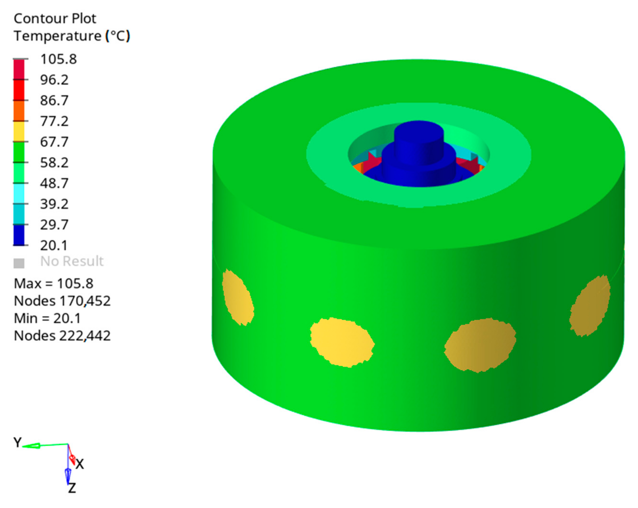
Once the mesh has been created and considering the conductive and convective heat transfers between the machine’s components, the thermal analysis has been carried out and the temperature distributions shown in the following figures have been obtained.
In Figure 20, it is possible to notice that the maximum temperature reached by the housing is equal to 77 °C, while the one reached by the shaft is about 30 °C. Figure 21 shows the temperature distribution within the active materials of the AFPM motor, whose average temperature is about 70 °C. In Figure 22, the PM and the rotor disc temperatures are displayed: the maximum temperature reached by the PMs is equal to 42 °C, whose value prevents the PMs from being demagnetized. The stator core is characterized by an average temperature of 87 °C, while the hottest spot has been detected in the windings that reach a maximum temperature of 105 °C, as it can be seen in Figure 23. Therefore, the temperature considered for the windings in the electromagnetic analyses matches the one resulting from the thermal simulation; besides, the insulation class required for this electric motor is the F-class, whose maximum operating temperature corresponds to 155 °C; this choice allows the motor to work in overload conditions for short periods of time without damaging the materials.

5. Conclusions

The direct-drive electric vehicle could be the future trend because it does not require transmission components and it allows to reduce the volume and the weight of the whole powertrain system while improving its efficiency. For this specific application, the axial flux permanent magnet motor represents a valid alternative to the traditional radial flux motor due to the possibility of placing it inside the vehicle’s wheels so that the reducer and differential gears can be suppressed. Due to the integration of the transmission gear with the motor, the heat dissipation, lubrication, protection, and torque output capacity of the in-wheel motor system can be significantly improved.
A small pure electric vehicle with gearless in-wheel motors has been considered as a case study; the basic drive architecture includes four axial flux motors installed directly inside the vehicle’s wheels.
In this paper, advanced and integrated electromagnetic, vibroacoustic and thermal analyses have been proposed in order to investigate, in a detailed and exhaustive way, the axial flux motor behavior.
In particular, the modal analysis and the frequency response analysis on a modal basis of the electrical machine’s mechanical system (complete with housing and shaft) have been carried out. Moreover, the deformed geometries at the resonance frequencies of all the motor components have been evaluated in terms of displacement, velocity and acceleration together with the noise produced by the vibrations of the analyzed AFPM motor. For the purpose of this paper, only the main results have been displayed: the rotor discs’ displacements due to the resonance phenomenon do not interfere with the nominal operating conditions of the analyzed axial flux PM machine.
In conclusion, considering that all the aspects evaluated for the application of the designed electric motor in the automotive field, together with the initial requirements (in terms of torque and power), have been satisfied (see Table 3), it can be stated that the analyzed AFPM motor is suitable for traction applications, showing indeed good power and torque densities. Moreover, the thermal analysis’ results reveal that the chosen insulation class is appropriate for the studied machine. Finally, it is possible to notice, from the vibroacoustic analyses, that the vibrations generated at base speed by the electric motor are acceptable; in fact, they produce an emitted sound lower than 65 dB, making the motor itself suitable, in terms of comfort and environmental impact, to be placed in an electric vehicle. After this multiphysics analysis, it is therefore possible to move on to the next step: a dynamic analysis of the electric vehicle that includes four in-wheel AFPM motors.

Author Contributions

Conceptualization, M.T. and M.V.; methodology, A.C. and M.V.; software, C.D.L., F.F. and M.O.; writing—original draft preparation, M.V.; writing—review and editing, A.C. and C.D.L.; visualization, A.C. and C.D.L.; supervision, M.T. and M.V. All authors have read and agreed to the published version of the manuscript.

Funding

This research received no external funding.

Conflicts of Interest

The authors declare no conflict of interest.

References

  1. Zhao, J.; Han, Q.; Dai, Y.; Hua, M. Study on the Electromagnetic Design and Analysis of Axial Flux Permanent Magnet Synchronous Motors for Electric Vehicles. Energies 2019, 12, 3451. [Google Scholar] [CrossRef] [Green Version]
  2. Gao, P.; Gu, Y.; Wang, X. The Design of a Permanent Magnet In-Wheel Motor with Dual-Stator and Dual-Field-Excitation Used in Electric Vehicles. Energies 2018, 11, 424. [Google Scholar] [CrossRef] [Green Version]
  3. Rahman, K.M.; Patel, N.J.; Ward, T.; Nagashima, J.; Caricchi, F.; Crescimbini, F. Application of Direct-Drive Wheel Motor for Fuel Cell Electric and Hybrid Electric Vehicle Propulsion System. IEEE Trans. Ind. Appl. 2006, 42, 1185–1192. [Google Scholar] [CrossRef]
  4. Deng, Q.-L.; Xiao, F.; Huang, W.-T. Design of New-type Axial Flux Permanent Magnet in-Wheel Machine. In Proceedings of the 2010 International Conference on Electrical and Control Engineering IEEE, Wuhan, China, 25–27 June 2010; pp. 5831–5834. [Google Scholar]
  5. Xiao, F.; Deng, Q.-L.; Liu, J.-C. Design of direct-drive axial flux permanent magnet in-wheel machine for electric vehicle. In Proceedings of the 2011 International Conference on Electrical Machines and Systems, Beijing, China, 20–23 August 2011; pp. 1–4. [Google Scholar] [CrossRef]
  6. Takorabet, N.; Martin, J.P.; Meibody-Tabar, F.; Sharif, F.; Fontaine, P. Design and optimization of a permanent magnet axial flux wheel motors for electric vehicle. In Proceedings of the 2012 XXth International Conference on Electrical Machines, Marseille, France, 2–5 September 2012; pp. 2635–2640. [Google Scholar] [CrossRef]
  7. Moreels, D. Axial flux motor topology: Will it dominate the future? In Proceedings of the International Motor Summit 2020, Zurich, Switzerland, 18–19 November 2020. [Google Scholar]
  8. Cetin, E.; Daldaban, F. Analyzing the Profile Effects of the Various Magnet Shapes in Axial Flux PM Motors by Means of 3D-FEA. Electronics 2018, 7, 13. [Google Scholar] [CrossRef] [Green Version]
  9. Hajnrych, S.J.; Jakubowski, R.; Szczypior, J. Yokeless Axial Flux Surface-Mounted Permanent Magnets Machine Rotor Parameters Influence on Torque and Back-Emf. Energies 2020, 13, 3418. [Google Scholar] [CrossRef]
  10. Mlot, A.; González, J. Performance Assessment of Axial-Flux Permanent Magnet Motors from a Manual Manufacturing Process. Energies 2020, 13, 2122. [Google Scholar] [CrossRef]
  11. Deng, W.; Zuo, S. Analytical Modeling of the Electromagnetic Vibration and Noise for an External-Rotor Axial-Flux in-Wheel Motor. IEEE Trans. Ind. Electron. 2018, 65, 1991–2000. [Google Scholar] [CrossRef]
  12. Gieras, J.F.; Wang, R.-J.; Kamper, M.J. Axial Flux Permanent Magnet Brushless Machines, 2nd ed.; Springer Netherlands: Dordrecht, The Netherlands, 2008. [Google Scholar]
  13. Capponi, F.G.; De Donato, G.; Caricchi, F.A. Recent Advances in Axial-Flux Permanent-Magnet Machine Technology. IEEE Trans. Ind. Appl. 2012, 48, 2190–2205. [Google Scholar] [CrossRef]
  14. Marignetti, F.; Colli, V.D.; Di Stefano, R.; Cavagnino, A. Design Issues of a Fractional-Slot Windings Axial Flux PM Machine with Soft Magnetic Compound Stator. In Proceedings of the IECON 2007—33rd Annual Conference of the IEEE Industrial Electronics Society, Taipei, Taiwan, 5–8 November 2007; pp. 187–192. [Google Scholar] [CrossRef]
  15. Chai, F.; Bi, Y.; Chen, L. A Comparison between Axial and Radial Flux Permanent Magnet In-Wheel Motors for Electric Vehicle. In Proceedings of the 2020 International Conference on Electrical Machines (ICEM), Online. 23–26 August 2020; Volume 1, pp. 1685–1690. [Google Scholar]
  16. Torregrossa, D.; Peyraut, F.; Cirrincione, M.; Espanet, C.; Cassat, A.; Miraoui, A. A New Passive Methodology for Reducing the Noise in Electrical Machines: Impact of Some Parameters on the Modal Analysis. IEEE Trans. Ind. Appl. 2010, 46, 1899–1907. [Google Scholar] [CrossRef]
  17. Deng, W.; Zuo, S.; Lin, F.; Wu, S. Influence of pole and slot combinations on vibration and noise in external rotor axial flux in-wheel motors. IET Electr. Power Appl. 2017, 11, 586–594. [Google Scholar] [CrossRef]
  18. Gieras, J.F.; Wang, C.; Lai, J.C. Noise of Polyphase Electric Motors; CRC/Taylor & Francis: Boca Raton, FL, USA, 2018. [Google Scholar]
  19. Li, D.; Wen, Y.; Li, W.; Feng, B.; Cao, J. Three-Dimensional Temperature Field Calculation and Analysis of an Axial-Radial Flux-Type Permanent Magnet Synchronous Motor. Energies 2018, 11, 1208. [Google Scholar] [CrossRef] [Green Version]
Figure 1. The direct-drive electric vehicle with in-wheel motors.
Energies 14 02107 g001
Figure 2. The double-sided axial flux permanent magnet motor.
Energies 14 02107 g002
Figure 3. The prototype of a laminated stator core.
Energies 14 02107 g003
Figure 4. The 3D views of the AFPM motor.
Energies 14 02107 g004
Figure 5. The scheme of the concentrated winding.
Energies 14 02107 g005
Figure 6. The back electromotive force at no-load.
Energies 14 02107 g006
Figure 7. The torque behavior at base speed (28 A).
Energies 14 02107 g007
Figure 8. The flux density distribution at 28 A (in Tesla).
Energies 14 02107 g008
Figure 9. The Torque vs. Speed curve.
Energies 14 02107 g009
Figure 10. The meshed mechanical model of the AFPM machine.
Energies 14 02107 g010
Figure 11. The axial magnetic forces on the permanent magnets.
Energies 14 02107 g011
Figure 12. The Fast Fourier Transform’s decomposition of a permanent magnet’s axial forces.
Energies 14 02107 g012
Figure 13. The deformed geometry’s velocities (mm/s) of the stator core at 600 Hz.
Energies 14 02107 g013
Figure 14. The velocity values of the stator teeth in the range of the analyzed frequencies.
Energies 14 02107 g014
Figure 15. The deformed geometry’s displacements (mm) of the rotor discs at 1531 Hz.
Energies 14 02107 g015
Figure 16. The displacement values of the rotor discs in the range of the analyzed frequencies.
Energies 14 02107 g016
Figure 17. The sphere of microphones used to detect the AFPM motor’s radiated sound.
Energies 14 02107 g017
Figure 18. The sound pressure level in (dB) on the chromatic microphone sphere.
Energies 14 02107 g018
Figure 19. The sound pressure level detected by the red zone’s microphones.
Energies 14 02107 g019
Figure 20. The temperature distribution in the AFPM motor’s housing.
Energies 14 02107 g020
Figure 21. The temperature distribution in the active materials of the AFPM motor.
Energies 14 02107 g021
Figure 22. The temperature distribution in the rotor discs with PMs.
Energies 14 02107 g022
Figure 23. An enlargement of the temperature distribution in the stator windings.
Energies 14 02107 g023
Table 1. AFPM motor requirements.
RequirementUnitValue
DC voltageV550
Maximum phase currentA<30
Base speedrpm840
Torque @ base speedNm>75
Efficiency%>80
Maximum speedrpm1200
Torque @ maximum speedNm>60
Maximum outer diametermm<200
Maximum axial lengthmm<80
Winding temperature°C100
Cooling system Forced-air
Table 2. Main data of the double-sided AFPM motor.
DataUnitValue
N. poles-N. slots 16–18
Outer diametermm160
Inner diametermm95
Axial lengthmm73.4
Slot widthmm15
Tooth heightmm23
PM thicknessmm5
Air gapmm0.7
Wire sizemm21.43
N. conductors per slot 108
Fe-Co alloy AFK1
NdFeB PM N38H
Table 3. Motor performance.
RequirementUnitValue
DC voltageV550
Winding temperature°C100
PM temperature°C100
Phase resistanceΩ0.85
Phase currentA28
Base speedrpm840
Torque @ base speedNm78
Power @ base speedkW6.86
Efficiency%85
Max speedrpm1200
Torque @ max speedNm67.5
Power @ max speedkW8.48
Table 4. Motor losses and efficiencies at different working points.
DataUnitValue
Joule losses @ base speedW1000
Iron losses @ base speedW110.4
PM losses @ base speedW19
Mechanical losses @ base speedW34.6
Efficiency @ base speed%85.4
Joule losses @ 900 rpmW1000
Iron losses @ 900 rpmW130
PM losses @ 900 rpmW19.8
Mechanical losses @ 900 rpmW50.8
Efficiency @ 900 rpm%85.8
Joule losses @ 1000 rpmW1000
Iron losses @ 1000 rpmW176.6
PM losses @ 1000 rpmW21
Mechanical losses @ 1000 rpmW70.2
Efficiency @ 1000 rpm%86
Joule losses @ 1100 rpmW1000
Iron losses @ 1100 rpmW235.7
PM losses @ 1100 rpmW22.5
Mechanical losses @ 1100 rpmW90
Efficiency @ 1100 rpm%85.8
Joule losses @ 1200 rpmW1000
Iron losses @ 1200 rpmW307.7
PM losses @ 1200 rpmW24.3
Mechanical losses @ 1200 rpmW110
Efficiency @ 1200 rpm%85.4
Table 5. Mechanical properties of the chosen materials.
Young’s ModulusPoisson’s RatioDensity
Fe-Co Alloy230,000 MPa0.298600 kg/m3
Copper1100 MPa0.338960 kg/m3
NdFeB100 MPa0.337400 kg/m3
Steel210,000 MPa0.307850 kg/m3
Table 6. Thermal properties of the chosen materials.
Specific HeatThermal ConductivityDensity
Fe-Co Alloy430 J/(kgK)32 W/(mK)8600 kg/m3
Copper377 J/(kgK)385 W/(mK)8960 kg/m3
NdFeB450 J/(kgK)7 W/(mK)7400 kg/m3
Steel434 J/(kgK)52 W/(mK)7850 kg/m3
Table 7. Internal heat sources of the machine.
Machine lossUnitValue
Joule lossesW/m31,785,000
PM lossesW/m3200,630
Iron lossesW/m3274,435
Table 8. Heat transfer coefficients of the machine’s surfaces.
ComponentUnitValue
External housingW/(m2K)42.3
Internal housingW/(m2K)20
External shaftW/(m2K)15
Internal shaftW/(m2K)25
Stator coreW/(m2K)21
WindingsW/(m2K)21
Rotor core + PMsW/(m2K)40
Air gap surfacesW/(m2K)28.8
Publisher’s Note: MDPI stays neutral with regard to jurisdictional claims in published maps and institutional affiliations.

