1. Introduction
Today, a significant amount of the energy is produced by fossil sources, which generate greenhouse gas emissions and pollution. Renewable energy sources (RES) are essential to reduce this dependence. This study focused on distributed RES. A hybrid energy system constituted by wind turbine generators (WTG), photovoltaic generators (PVG), and batteries has been applied for grid-connected operation [
1] and in various autonomous applications [
2]. An autonomous system based on photovoltaic and wind energy with a PI regulator is described in [
3]. Energy efficiency and sizing of wind/photovoltaic hybrid systems for electrification of marine oil well heads are being studied [
4]. As a result, a pilot project allowing a grid-connected high-gain photovoltaic system is proposed in [
5]. The design of an inverter for a hybrid power system is discussed in [
6]. A hybrid system coupled to the grid and a new inverter topology was designed in [
7]. Power converters and control units are essential for energy and its management, as well as for the maximum power supplied by PVG and WTG. For this reason, there are different approaches to pursuing maximum power points (MPPs) in the relevant published literature, such as incremental conductance [
8], the parasitic capacity method [
9], or the perturbation and observation method [
10]. They depend also on the environmental parameters. Nevertheless, the uncertainties related to these conditions have reduced the performance of these techniques, particularly under the effect of variations in solar radiation, wind speed, and temperature. Fuzzy logic is usually used to achieve the maximum power delivered by PVG [
8,
10,
11] and WTG [
12,
13,
14] because it facilitates the application of energy management rules. In addition, it does not require a perfectly known mathematical model. Moreover, fuzzy logic’s robustness and adaptability in the presence of parameter changes or unbalances in the system are well known.
In addition, conventional boost or buck/boost power converters are used to provide higher output voltage than input voltage [
15] for the grid connection. These converters require a higher duty cycle to achieve higher voltage, but this implies higher input current and, consequently, a reduction of the converter performance. An alternative choice could be the conventional isolated converters [
16,
17,
18], for example forward converters, fly-back, half-bridge, integral bridge, and push-pull. The voltage gain of these converters is dependent on the transformer ratio or on the coupled inductances. As a result, these converters can achieve high-voltage gain by using a higher transformer ratio. However, these converters absorb a discontinuous input current, making them unsuitable for renewable energy applications such as photovoltaic panels and wind turbines. They would need large input filter capacitors to operate with RES. In addition, the leakage inductance of these converters leads to an increase in voltage peaks on their switches. As a result, the clamping circuits to protect the switches make the system design complex. The conventional converters reported above have been the subject of several studies [
19,
20]. A new high-voltage gain DC-DC converter was developed in [
20] and it is used in this paper with a fuzzy logic controller to ensure a robust performance in variable environmental conditions (temperature, solar radiation, and wind speed).
Different current regulation techniques have been proposed to control the power transfer to the single-phase distribution line and to reduce the harmonic distortions in the alternating current: hysteresis current regulation [
21,
22], voltage orientation regulation [
23,
24], and resonance proportional regulation (PR) [
25,
26]. Active reactive power control was used in this paper to command the single-phase inverter.
The generation of different pulse width modulation (PWM) pulses for different power converters was conceived in this article by using a Spartan 3E field programmable gate arrays (FPGA) board. FPGA very large-scale integration (VLSI) technology offers a fast and flexible system with more benefits than other traditional technologies. The ISE design suite software can easily optimize and control system parameters, such as frequency, current amplitude, voltage amplitude, number of PWM impulses in a half cycle, etc., without modifying the hardware circuit.
FPGA circuits have been successful in minimizing execution time by implementing parallel processing and rapid design prototyping; moreover, they improve the quality of hybrid power system control, thanks to new technologies of digital systems [
11,
27,
28]. In fact, response time is improved, exceedances and oscillations are minimized, and power losses are reduced. All these advantages of real-time implementation are useful for hybrid control systems.
Recently, different structures of the hybrid system based on RES have been developed in the literature [
10,
15,
29,
30,
31] and different methods have been developed to extract the maximum available power [
9,
10,
11,
12,
13,
32,
33,
34,
35]. Fuzzy logic control (FLC) is one of the best recognized techniques in maximum power point tracking (MPPT) [
13,
36,
37,
38]. In addition, the principal advantage of the fuzzy logic method is the possibility of determining the maximum power from both voltage and current sensors.
This paper is structured as follows: the hybrid power generation system modeling is introduced in
Section 2.
Section 3 describes different control strategies to ensure power transfer with minimum losses. Some simulation results using Matlab/Simulink are presented in
Section 4 to validate and simulate the proposed hybrid architecture. The register transfer level (RTL) architectures, simulations, and implementation steps of the various commands are illustrated and discussed in
Section 5. Conclusions are then included at the end of this work.
4. Architecture of the Fuzzy Logic Controller on FPGA
This section explains how the previous controllers were implemented on an FPGA.
Figure 8 shows a method to modify the values for the FPGA board consisting of two parts: the first shows the decimal part and the second shows the fractional part. In addition, we must calculate the number of bits (m) that denotes the integer part and the other forms of the fractional part (n). A number written in the fixed point is mentioned.
The Mamdani’s method is the most popular technique dedicated to FLC. The fuzzy rule is proven in the following equation:
where
is the compute output values and k = 1, 2, …, 25.
In
Figure 9, the steps of the proposed control are explained in detail.
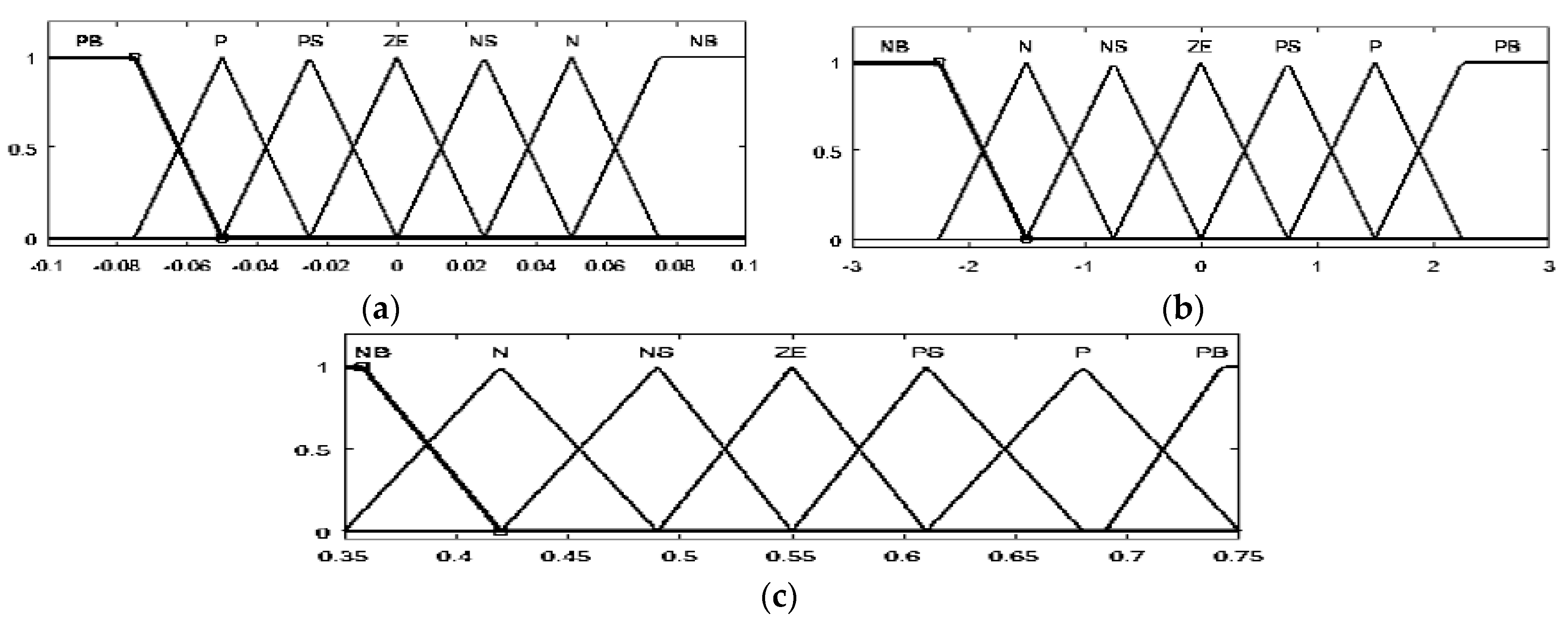
The Mamdani technique simplifies the processing of materials thanks to its simple min-max structure. A summary of the internal structure of the controller can be found in
Figure 4. However, the fuzzification of the two input parameters generates the appropriate linguistic values and membership functions (B1…B5) and (B11…B15). In addition, the association of antecedent pairs in the rule structure is essentially based on an operator AND logic. Then, all rules are combined in a max operation via the max block of the diagram. Therefore, the weighted average approach is recognized as one of the defuzzification processes that is suitable for implementation on hardware. Since the output membership functions are usually symmetrical, the fuzzy average can be applied as a weighting for the defuzzification process. Simultaneously, this method is composed of two arithmetic operations: multiplication operations with a constant process and a single division process.
The inputs/outputs signal of the ADC and the DAC converters situated on the Spartan 3E FPGA board are represented by 12 bits. As a result, the length of the integer and decimal part of each input/output signal is chosen according to the value of the signal to be displayed. For example, the input signals may be a 12-bit vector (m = 7, n = 5). As a result, the value of the open circuit voltage should not be greater than the open circuit voltage, such as 92 V. In addition, a 0 to 1 output value of the duty cycle was obtained, so the duty cycle was defined as 12 bits, and we decided to use a 10-bit representation for the decimal part.
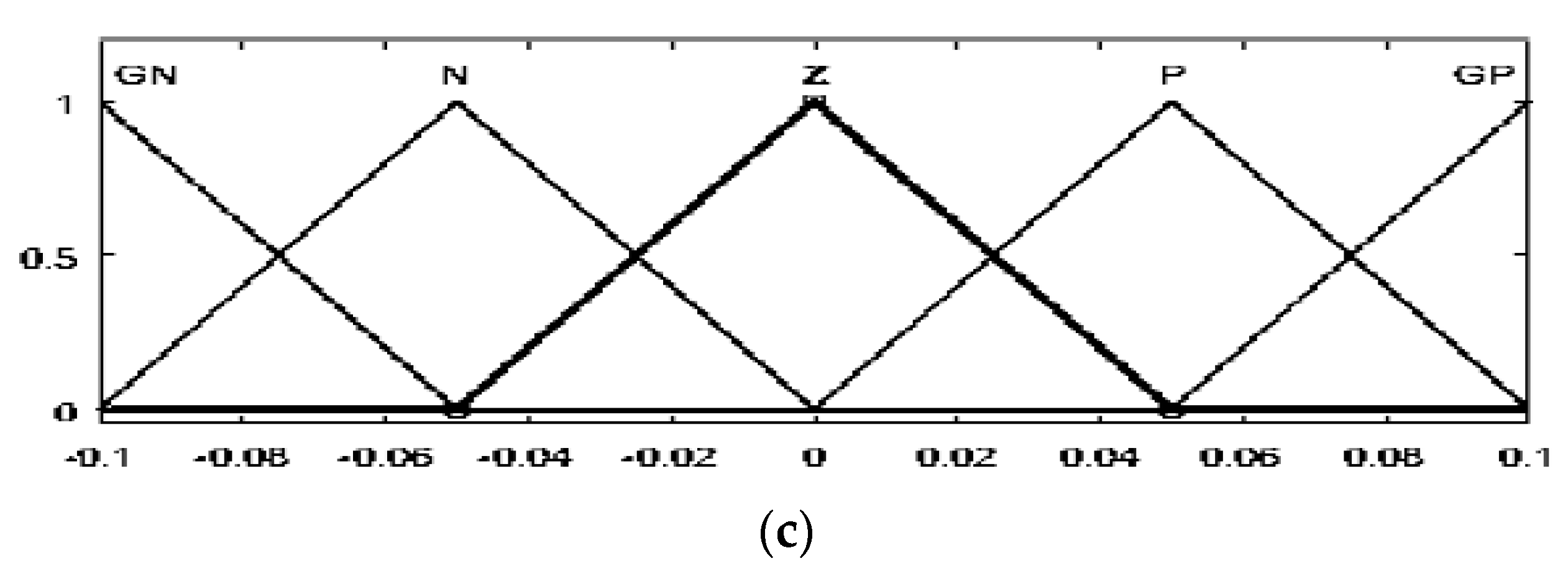
The high-voltage gain DC-DC converter was also controlled by fuzzy logic. With respect to inputs and output, seven membership functions were defined for the fuzzification and defuzzification processes depending on the following linguistic variables: grand negative (GN), negative (N), negative small (NS), zero (Z), positive small (PS), positive (P) and grand positive (GP). The same methodology of the FLC structure shown in the functional diagram in
Figure 9 was implemented to represent the fuzzy controller architecture designed for the proposed converter.
6. Conclusions
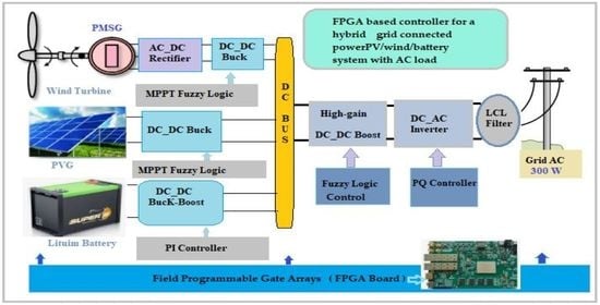
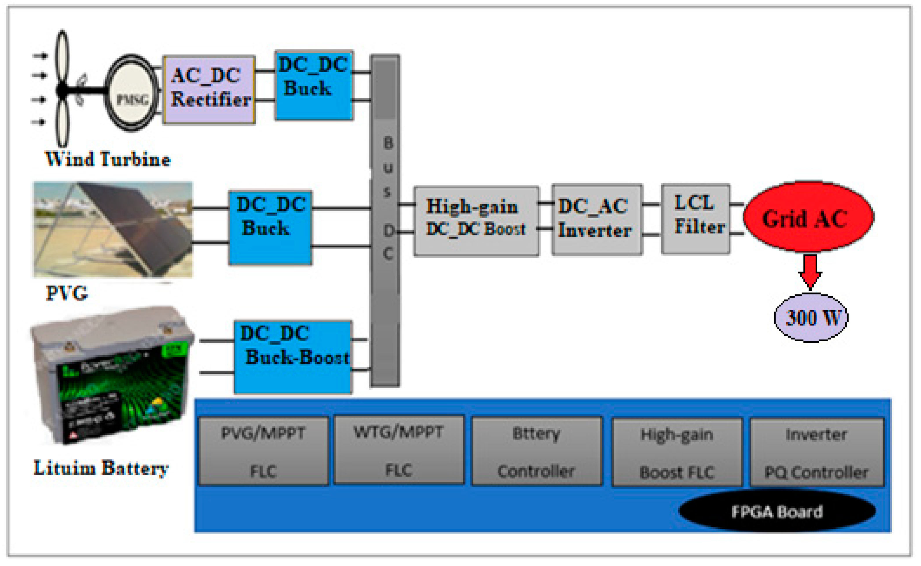
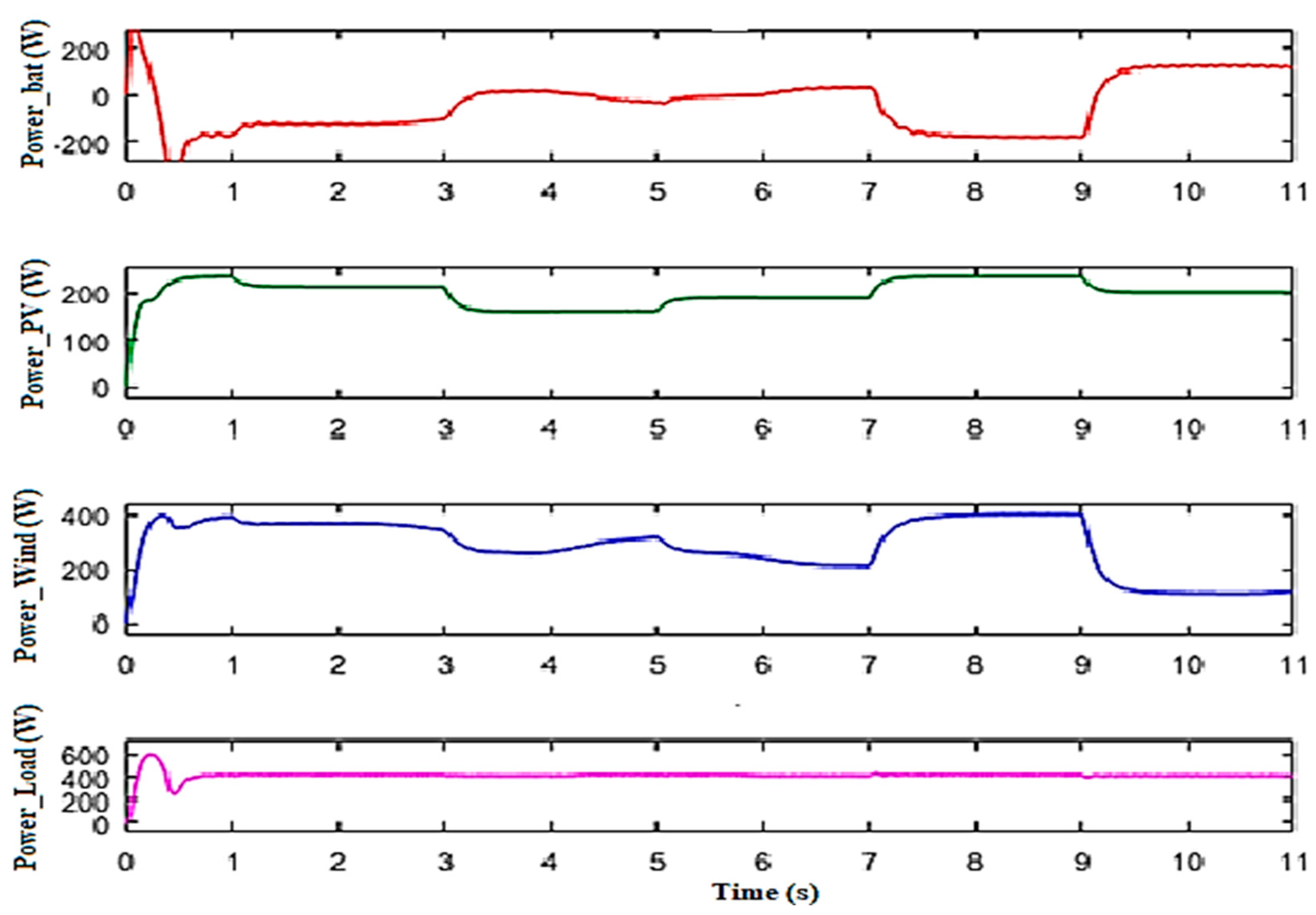
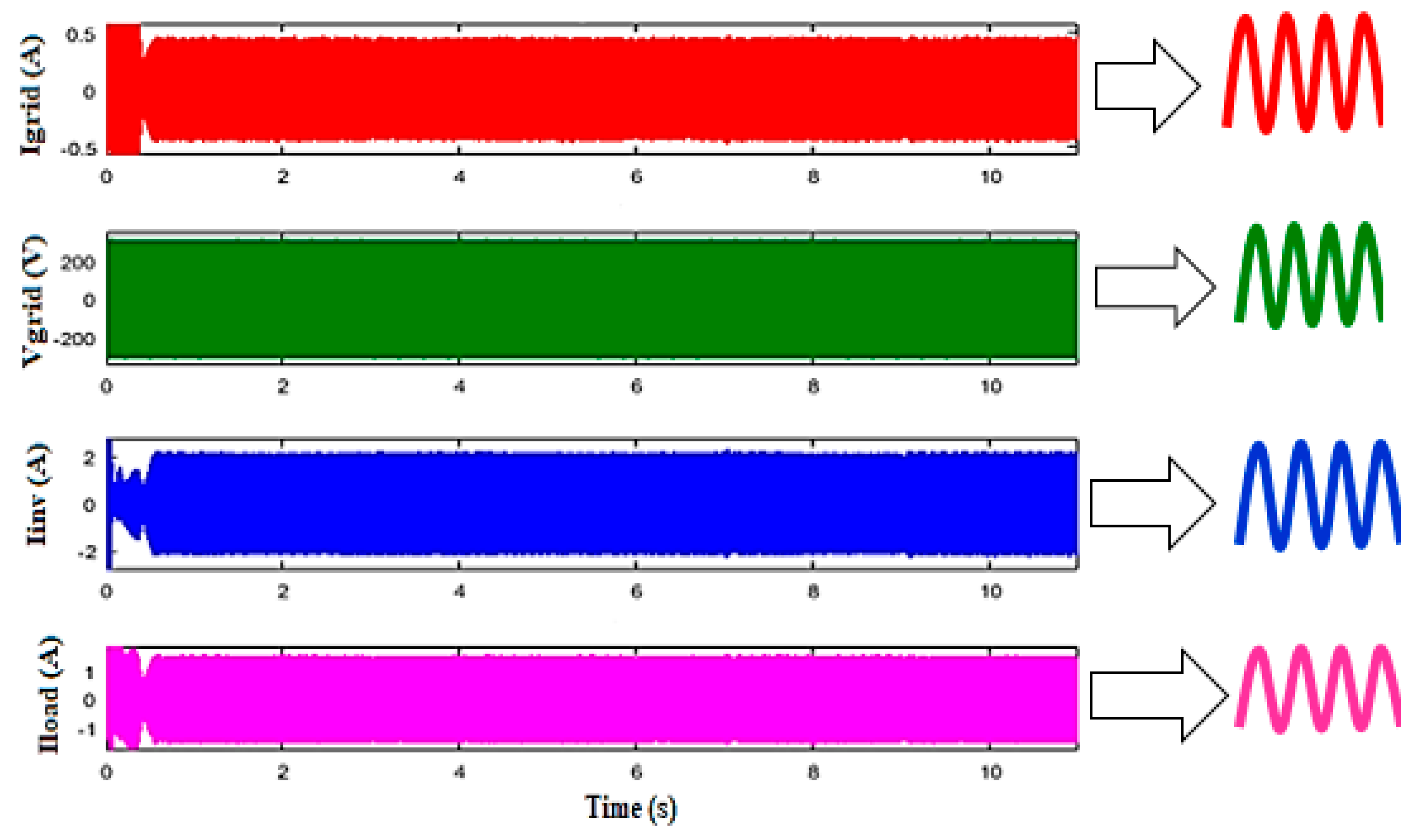
This paper presents the modeling and simulation of a control system composed by five controllers for a grid-connected PV/wind/battery hybrid with AC load. The proposed system was validated in MATLAB/SIMULINK and ISE Design for implementation of the code in the FPGA card.
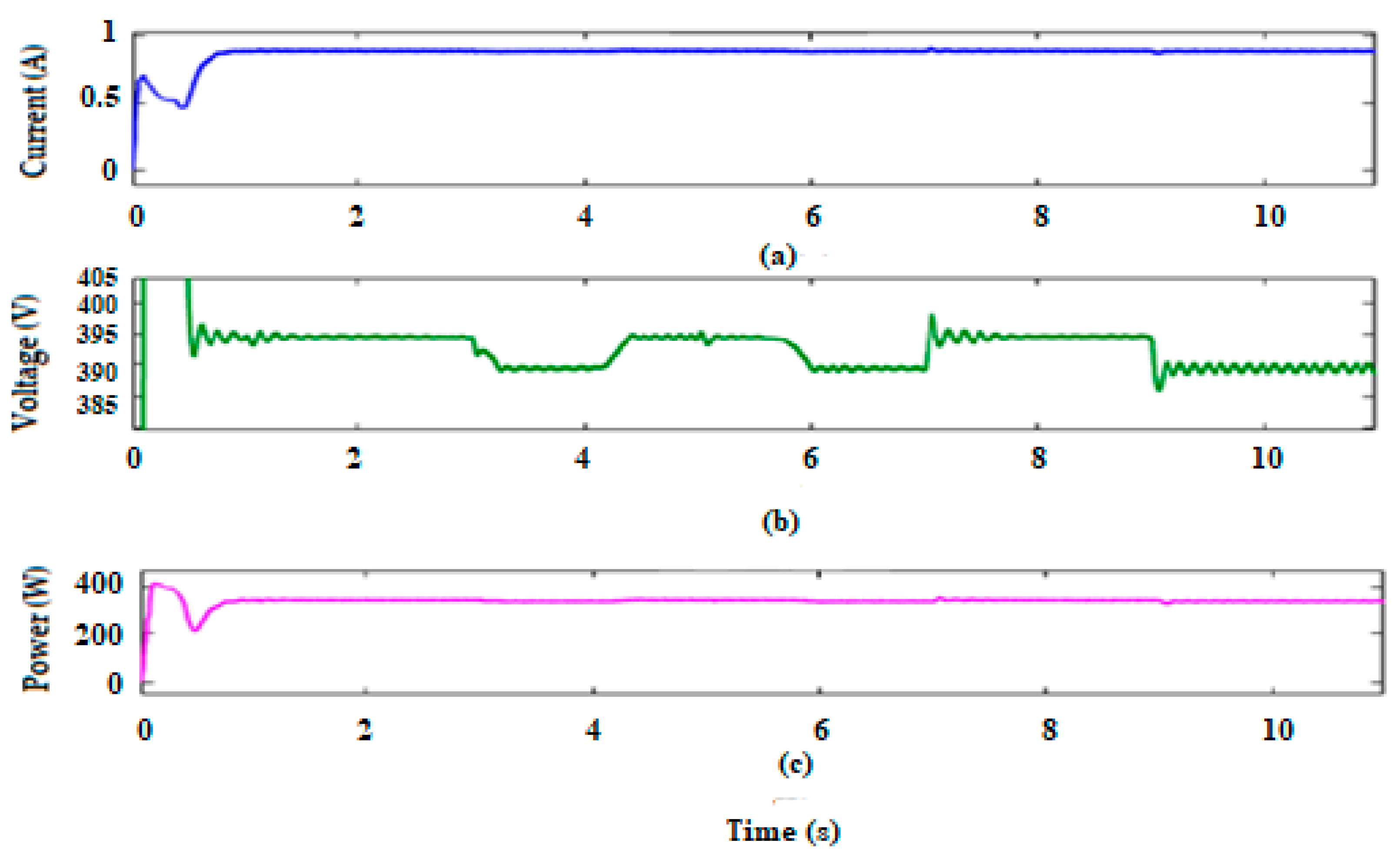
More precisely, a control strategy based on MPPT FLC using the algorithm of the incremental conductance was created to capture the maximum power extracted from the PVG and WTG generators. Additionally, a FLC that maintains a fixed DC link voltage at the output of the proposed converter was included. While the PQ control was implemented to control the inverter, the battery controller employed two PI controls: the first was designed to regulate the DC bus voltage and the second was created to manage the current controller.
The integration of a high-voltage gain DC-DC converter allowed us to increase the 24 V voltage generated by the DC bus to a voltage appropriate for the inverter of about 400 V and to minimize power losses to ensure maximum efficiency of the proposed system.
The challenges and non-linearity of PV and wind turbine (WT) systems are influenced by solar radiation, temperature, and wind speed, resulting in power losses and reduced efficiency. To obtain a fast response time and to take into account time constraints, we developed and simulated different architectures to facilitate VHDL programming and make control executable in real time. Thus, different controllers were developed and simulated in VHDL. The innovative design presented in this work requires a small unit of energy sources and presents an appropriate solution for domestic applications.
Future work should aim to experimentally verify the feasibility of the new control scheme for real-time applications of hybrid power systems.


