Article

Design and Analysis of a Dual Airgap Radial Flux Permanent Magnet Vernier Machine with Yokeless Rotor

1
Electrical Engineering Department, Incheon National University, Songdo 22012, Korea
2
Electrical Engineering Department, The University of Lahore, Lahore 54000, Pakistan
3
Electrical Engineering Department, Institute of Southern Punjab, Multan 60750, Pakistan
*
Author to whom correspondence should be addressed.
Energies 2021, 14(8), 2311; https://doi.org/10.3390/en14082311
Submission received: 14 March 2021 / Revised: 16 April 2021 / Accepted: 18 April 2021 / Published: 20 April 2021
(This article belongs to the Special Issue Advanced Techniques for High-Performance Permanent Magnet Motors)

Abstract

:
This paper presents a novel topology of dual airgap radial flux permanent magnet vernier machine (PMVM) in order to obtain a higher torque per magnet volume and similar average torque compared to a conventional PMVM machine. The proposed machine contains two stators and a sandwiched yokeless rotor. The yokeless rotor helps to reduce the magnet volume by providing an effective flux linkage in the stator windings. This effective flux linkage improved the average torque of the proposed machine. The competitiveness of the proposed vernier machine was validated using 2D finite element analysis under the same machine volume as that of conventional vernier machine. Moreover, cogging torque, torque ripples, torque density, losses, and efficiency performances also favored the proposed topology.

1. Introduction

The direct-drive systems have been an attractive solution to eliminate the mechanical gears and achieve high torque at low speed, low noise, very low vibrations, and high reliability. These systems are very eagerly pursued in applications such as wind power generations, elevators, and ship propulsions. However, designing the direct-drive machines for regular industrial operations yields large dimensional structures that prevent their wide applications. One of the major characteristics of direct drive systems is the high torque density; hence, various machines were researched to achieve a high torque density while taking the weight and volume considerations. For low-speed operations, the machine needs to have a large pole number and large slot numbers, which increases the overall size of the machine [1]. Moreover, the armature winding is relatively difficult for high torque, low-speed machines due to a large number of poles. The stator end windings length is also increased for a large number of slots, which in turn increases the overall copper losses in PM machines [2].
Among various other designs, permanent magnet vernier machines have gained considerable interest as a promising alternative for direct-drive applications [3]. Low-speed, high-torque performance is the key feature of a permanent magnet vernier machine (PMVM) that makes it a suitable choice for direct drive applications [4,5,6,7]. The PMVM is designed with a higher number of rotor magnet poles as compared to the stator winding pole pairs in the conventional PM synchronous machine. This combination of stator and rotor poles produces the so-called “magnetic gearing effect” with the goal that a small movement of the rotor produces a huge flux change, which generates high torque [3]. Generally, the PMVM exhibits low-torque ripple, and therefore they are a suitable candidate for the applications where vibration, noise, and reliability of the gearing system are the main concerns [8,9]. A comparison between PMVM and conventional permanent magnet synchronous machine (PMSM) for wind generators was presented in [10], which shows that the torque performance of the PMVM is better than that of the conventional PMSM having similar volume and outer dimensions. Moreover, the PM usage in PMVM is also reduced as compared to the conventional PMSM. Recently many topologies of PMVM have been investigated in order to improve the torque density, reduce torque ripple, and improve efficiency. In [11,12], the dual airgap PMVM was introduced to improve the airgap flux density of the machine and utilize the space within the machine while reducing the flux leakage between stators and rotor. The dual airgap spoke type structure was presented in [13,14], and it was shown that the spoke type magnets with flux focusing effect produces high torque density and an improved power factor as compared to the single airgap model having similar physical dimensions.
Considering the design of the PMVM, the rotor contains a higher number of magnet poles as compared to the stator in the machine. This in turn increases the magnet volume consumption as well as the manufacturing cost of the PMVM as compared to other PM machines [15]. The consequent pole PMVM is a special type of topology in which the magnets with the same polarity are arranged between the rotor teeth to form the basic consequent pole structure [16]. It was found that the consequent pole structure requires less volume of magnets and improves the flux linkage between the stators and reduces the leakage flux. To further improve the flux linkage between the stators and rotor, the authors of [17] presented PMVMs with Halbach-array magnet in slot opening and consequent poles in the rotor with the claim to improve the torque density by 55%. Recently, another novel topology of dual airgap PMVM with Halbach-array magnets in the rotor was presented in [18] for a 43% improvement in torque as compared to the conventional PMVM. Moreover, a dual rotor PMVM was introduced with 50% higher torque than the single airgap PMVM [2]. Other novel topologies of dual stator single-rotor PMVM were also presented in [19,20] in order to achieve the high-torque density as compared to the single airgap machine, which increased the cost of the manufacturing because of PMs used on the inner stator and the rotor. Furthermore, the rotor iron yoke caused the reduced flux linkage between two stators, which in turn affected the overall torque performance of the machine.
Alternately, a dual stator PM machine without an iron yoke rotor was presented in [21,22] in order to improve the torque per magnet volume and reduce the cost as well. The motor with a yokeless rotor showed much-improved torque density and reduced torque ripple as compared to the iron yoke rotor motor. However, the torque per magnet volume in this machine was not significantly improved because the volume of the magnet was similar in both the iron and yokeless rotor models. Moreover, the iron yoke rotor can be subject to more saturation because of the double-sided magnets as well as the high currents in the windings. This saturation may lead to the asymmetric flux distribution as well as heat production in the rotor core [23]. The PM brushless DC (BLDC) machine with improved techniques for torque per magnet volume was presented in [24]. However, the issues of reduced flux linkage between two stators due to the sandwiched rotor yoke in radial type PMVM were not addressed in the literature.
This paper proposes a novel dual airgap radial-type PMVM with a yokeless rotor for improved torque per magnet volume and improved average torque. The advantage of using the yokeless rotor is providing the effective flux linkage between the two stators as well as reducing the usage of overall magnet volume in the machine. The proposed machine was compared with the dual airgap radial type PMVM with a sandwiched rotor with iron yoke, in terms of torque per magnet volume, average torque, cogging torque, and efficiency. This paper is arranged in the following way: Initially, the topologies of the yoke and yokeless rotor PMVMs are presented. The operating principle and design concept of both models are presented. The 2D finite element method (FEM) analysis was utilized to evaluate the proposed topology and compare it with the iron yoke rotor model at a similar volume. The prototype experiment was performed at rated speed for the verification of the 2D-FEM simulations. No-load experiment results for back electromotive force (EMF) are presented in this paper. The complete results of the experiment for the prototype and comparison with the simulation results will be presented in the next version of this paper.

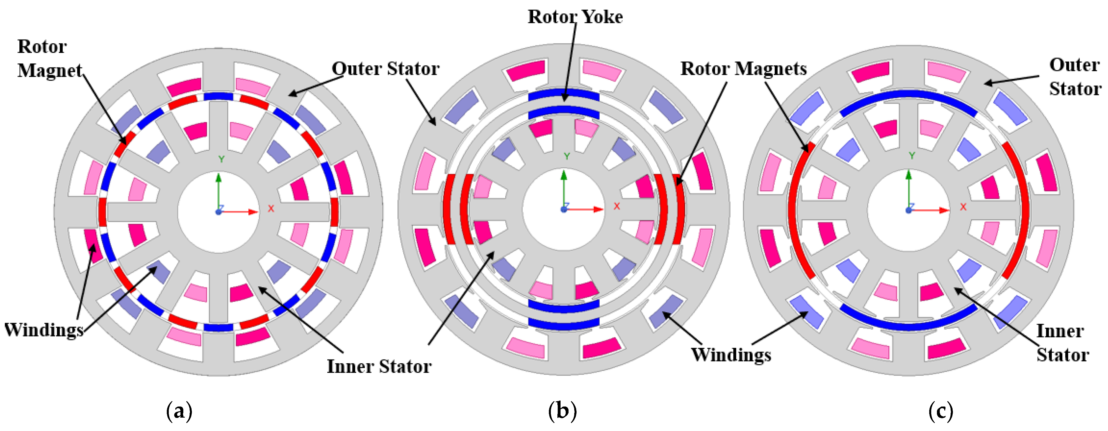
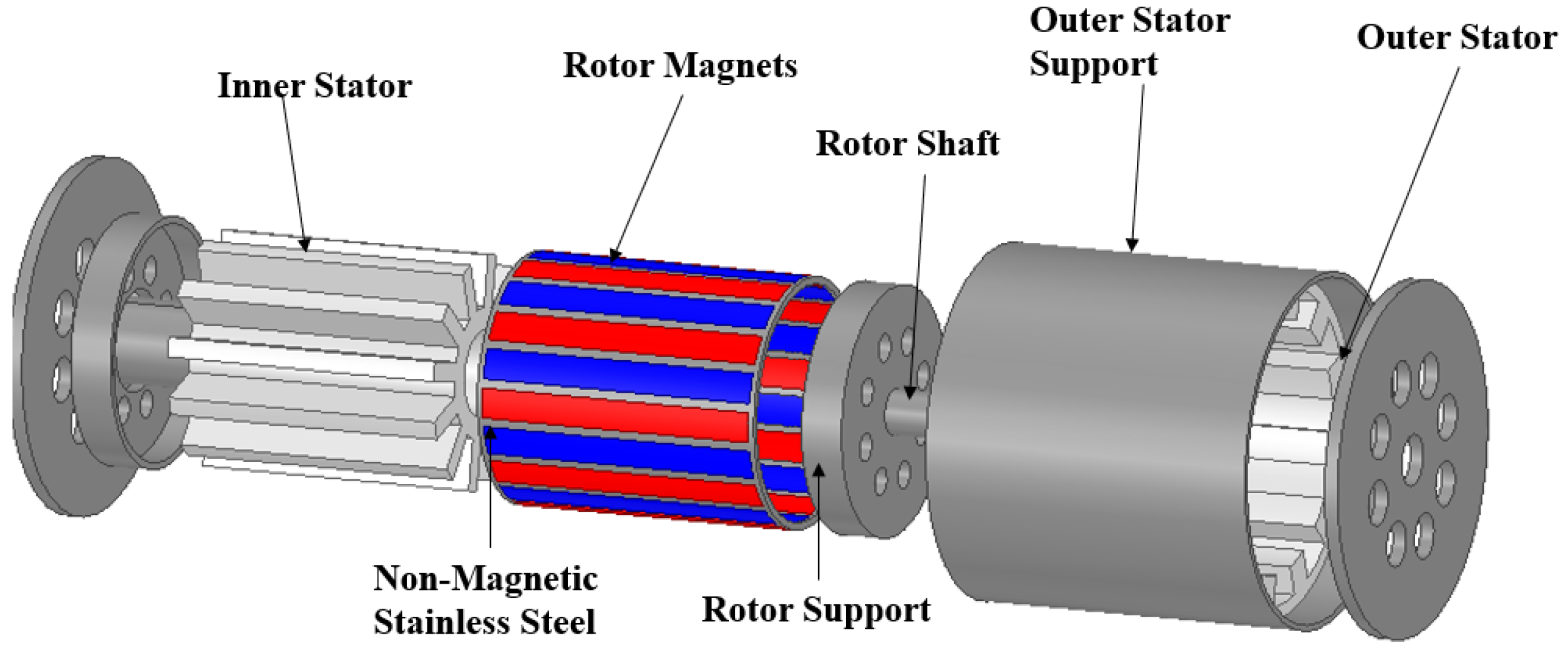
2. Machine Topology, Specifications, and Working Principle

Dual airgap radial flux (DARF)-type PMVM machine topologies are shown in Figure 1. Figure 1a shows the basic structure of DARF PMVM with an iron yoke rotor sandwiched between two stators and contains two layers of surface-type NdFeb magnets in back-to-back position with the same polarity at each position. The presence of a magnetic rotor core in the DARF machine may cause additional losses and cannot be suitable for the applications where rotor core loss is a critical consideration. The outer and inner stators are of conventional toothed-pole structure to realize the flux modulation effect and the windings are of the conventional distributed type.
Figure 1b shows the structure of the proposed dual airgap PMVM with the yokeless rotor. This model consists of a rotor without the iron core, having a single layer of magnets. The surface-type magnets in the yokeless rotor are fixed with non-magnetic support. The absence of an iron core in the yokeless rotor model avoids the issues present in the iron rotor yoke model. Moreover, the yokeless rotor motor can be favorable in applications sensitive to the cogging torque and robust design of the rotor.
The design of PMVM is based on the interaction of the magnetic field produced by the permanent magnets and the rotating field produced by the stator windings, as presented in [25]. The relationship between the number of stator poles, rotor poles, and stator slots for the vernier machine used in this paper is shown in Equation (1) as
±Ps/2 = Pr/2 − Ss
where Ps, Pr, and Ss represent stator poles, rotor poles, and stator slots, respectively. The “+” and “−” signs both result in similar stator MMF. In the time-frequency domain, the rotor MMF and stator MMF rotate in the same direction for the “+” criterion and the opposite direction for the “−” criterion. Both the machines contain 12 stator slots with 4 winding poles and 20 rotor poles. The detailed specifications and dimensions of these machines are presented in Table 1.
The operation principle of PMVM is based on magnetic flux modulation. In PMVM, the stator windings generate the low-order harmonic field, and the stator poles perform the flux modulation. The rotor poles generate a high-order harmonic field that combines with the stator space harmonic field and produces the useful torque due to the “magnetic gearing effect”, which results in a high flux change by just a small rotation of the rotor to produce high torque.

3. Performance Evaluation and Comparison of Existing and Proposed Machine
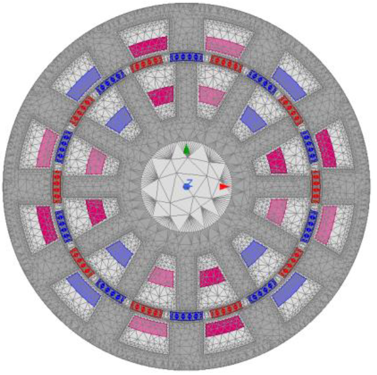
The performances of both the models were analyzed and compared at no-load and load conditions, which included the electromagnetic torque, cogging torque, torque ripple, mutual inductance, core loss, torque density, and efficiency. For a fair comparison, the outer dimensions of both models were kept constant, as listed in Table 1.

3.1. Mesh Settings

Surface type mesh was assigned to the stator, rotor, and band in the 2D FEM analysis. The maximum length of the mesh was selected to be 0.5 mm in the no-load and load simulations. Figure 2 shows the mesh layout assigned to the machine during simulation.

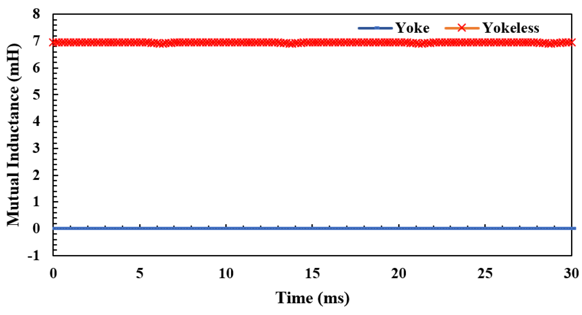
3.2. Reluctance and Inductances

The reluctance parameter is affected by the length of the flux path. The flux path in the dual airgap machine passed from the rotor to the outer airgap and outer stator, back to the rotor, inner airgap, and finally the inner stator. Figure 3a shows the flux path in DARF-PMVM with an iron yoke rotor, whereas Figure 3b shows the flux path in DARF-PMVM with the yokeless rotor. It can be observed that the flux path in the model with a yokeless rotor followed the shorter path because of the absence of the rotor yoke and the presence of only one layer of magnets. The shortening of the flux path affected the value of reluctance. The reluctance of each part in the motor played an important role in the generation of electromagnetic torque and affected the torque ripple as well.
Figure 4a,b shows the reluctances of the flux path for one pole that included airgap and magnet layers in both machines. Here, g1, m1, g2, and m2 denote the reluctance of the inner airgap, the inner layer of the magnet, outer airgap, and outer layer of the magnet, respectively.
The overall reluctance tot for one complete flux path of the iron yoke model can be written as Equation (2):
tot = 2 × g1 + 2 × m1 + 2 × m2 + 2 × g2
whereas the reluctance of one layer of magnets was absent in the case of the yokeless rotor model, which in turn reduced the overall length of flux path in this model, as shown in Figure 4b.
The overall reluctance tot for one complete flux path of the yokeless model can be written as Equation (3):
tot = 2 × g1 + 2 × m1 + 2 × g2
The reluctance of core was neglected in both models due to high permeance.
The inductance was inversely related to the reluctance and directly proportional to the square of the number of turns of the coils as Equation (4):
L = N2/tot
where N is the number of turns in the coils that were kept constant for both machines and tot is the reluctance of the flux path.
As can be seen in Equations (2) and (3), the reluctance was reduced in the DARF-PMVM with a yokeless rotor due to the absence of the second layer of the magnet. Hence, the inductance was increased in the yokeless rotor model as compared to the model with rotor yoke. Figure 4 shows the mutual inductance in the yoke model and yokeless model. It can be seen that the inductance of the yokeless rotor model was much higher as compared to the model with rotor yoke.
The shortening of the flux path helped to increase the torque density as discussed for axial flux type machines in [23]. Furthermore, the mutual inductance between the two stators in the yokeless model was increased as compared to the model with an iron yoke rotor, as shown in Figure 5.

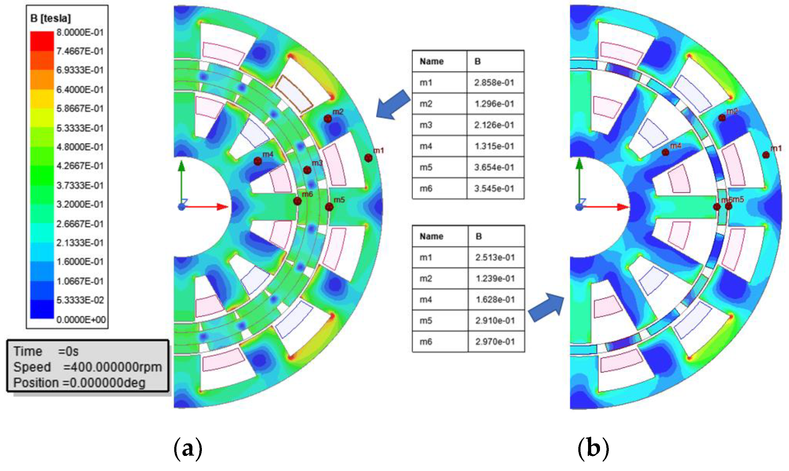
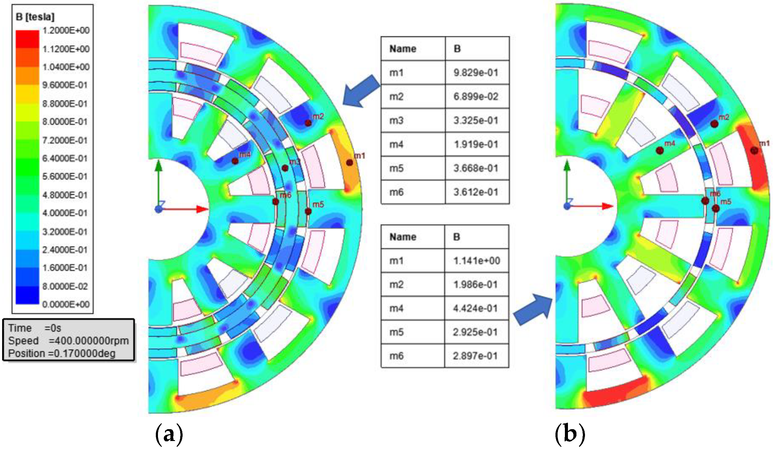
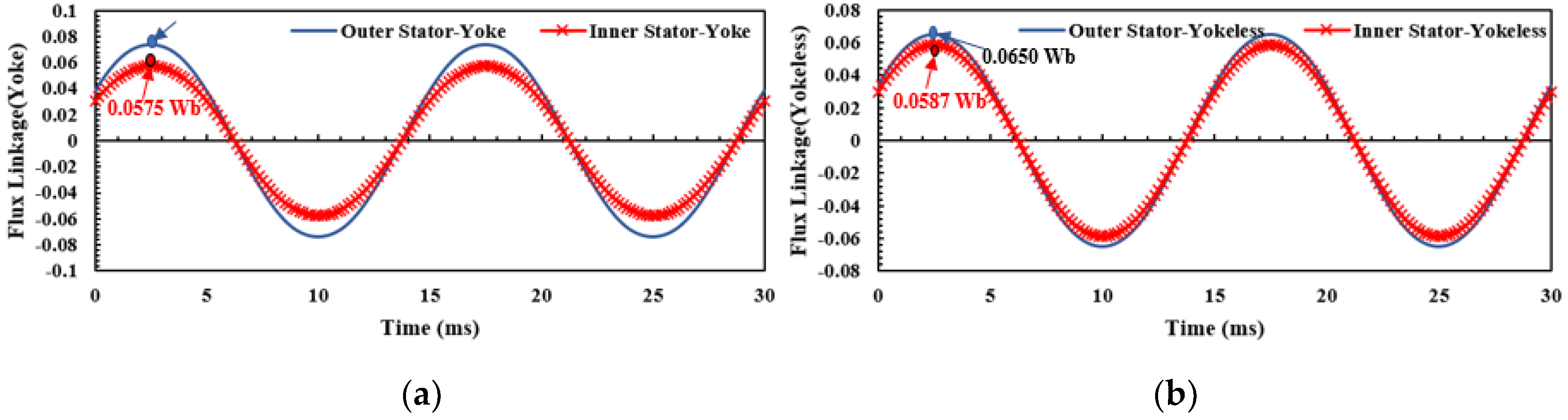
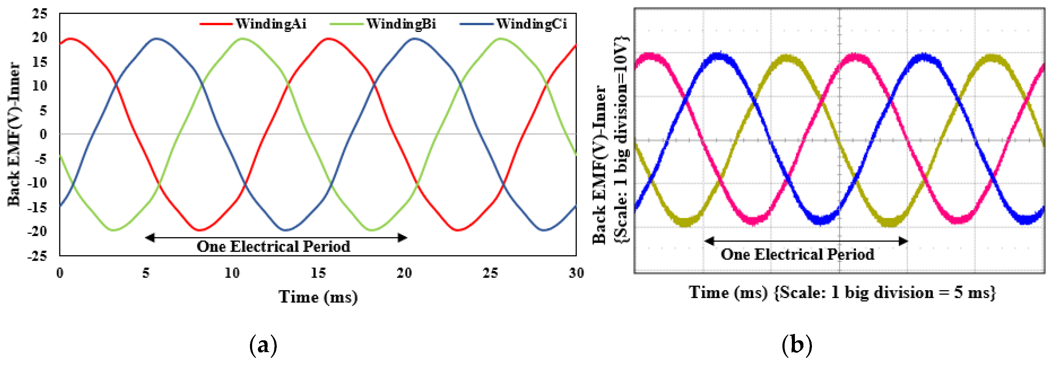
3.3. Flux Density, Flux Linkage, and Back EMF

Flux density distribution depends upon the rotor poles and hence the inductance as well. The flux densities of DARF-PMVM with iron yoke rotor and yokeless rotor models at no-load and load case are shown in Figure 6 and Figure 7, respectively. The no-load flux density was higher in the case of the iron yoke rotor model because of the higher volume of magnets used in the iron yoke rotor model. In contrast, the flux density of the yokeless rotor model was higher at load case as compared to the model with iron yoke rotor due to increased mutual inductance in the yokeless rotor model. The flux linkage at no load in both models is shown in Figure 8. The back EMF comparison is shown in Figure 9.
In the DARF model with an iron yoke rotor, the flux linkage of the outer stator was higher than that of the lower stator. The difference in flux linkage in both stators was due to the different air-gap flux densities in upper and lower airgap. This was because of the relatively small radius of the inner airgap, which in turn reduced the span of magnets at the lower airgap. This, in turn, induced different back EMF in both stators, as shown in Figure 9. On the other hand, in the yokeless rotor model, the flux linkage in both stators was almost equal due to similar magnet span at both airgap sides, which contributed similar back EMF in both stators.

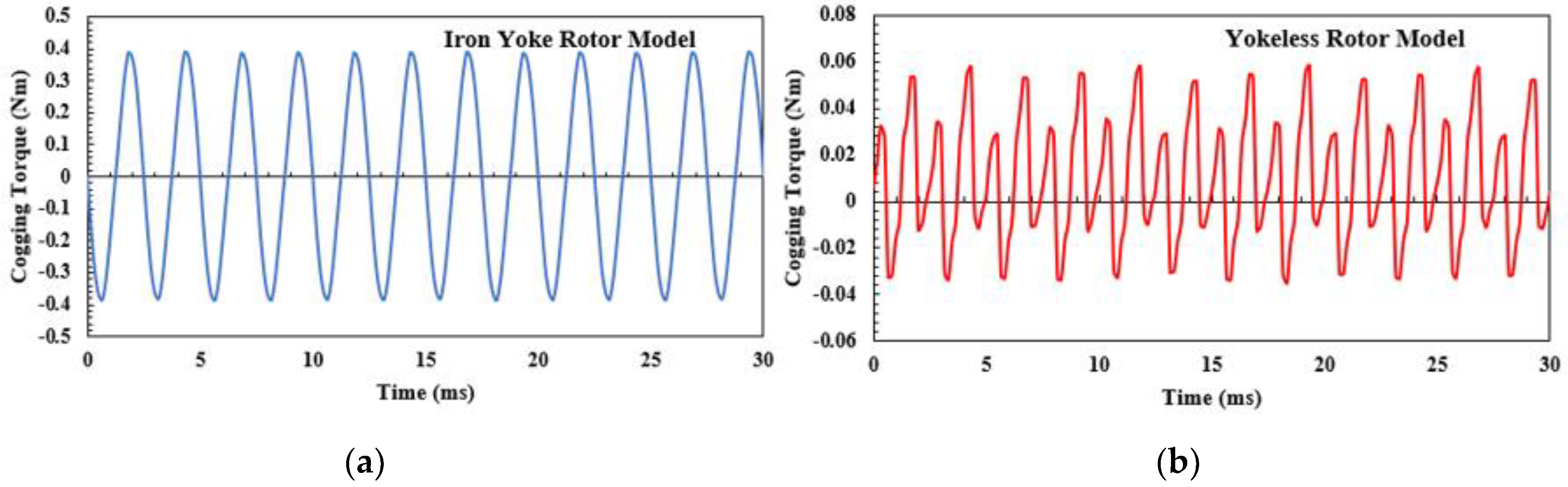
3.4. Cogging Torque and Torque Ripple

Cogging torque and torque ripple play an important role in analyzing the performance of the machines as they can produce vibrations and noise in the machines. Cogging torque is the result of interaction between permanent magnet flux and stator teeth. In Figure 10, the cogging torque for the yokeless rotor model and the iron yoke rotor model is compared at similar operating conditions.
According to the results, the proposed DARF model with the yokeless rotor showed a significant reduction in cogging torque as compared to the DARF model with an iron yoke rotor. The torque ripple also showed the same trend as cogging torque in both models. The torque ripple in the DARF model with the yokeless rotor core was 2.5%, as compared to the value of 5.9% torque ripple in the model with an iron yoke rotor.

3.5. Electromagnetic Torque and Torque Density

The electromagnetic torque waveforms of the proposed DARF model with a yokeless rotor and the model with an iron yoke rotor are presented in Figure 11. The average torque of the proposed DARF model with a yokeless rotor was slightly less as compared to the iron yoke rotor model, as mentioned in Table 2. Furthermore, the magnet volume used in this model was 50% less than the magnet used in the iron yoke rotor model. The improvement in the torque was due to the increased mutual inductance and improved flux linkage in both stators in the DARF model with a yokeless rotor while the magnet volume was reduced to half as compared to the model with an iron yoke rotor. Both machines were analyzed at similar physical dimensions and overall volume. The torque density of the proposed machine was slightly reduced as compared to the iron rotor core model due to a slightly reduced electromagnetic torque in the yokeless model, as shown in Table 2.
Permanent magnets account for a major part of the machine manufacturing cost; therefore, a 50% reduction in the magnet volume means the cost of the machine will also be significantly reduced. The comparison in Table 2 reveals that the torque per magnet volume of the yokeless rotor model was 87% higher than that of the DARF model with an iron yoke rotor.

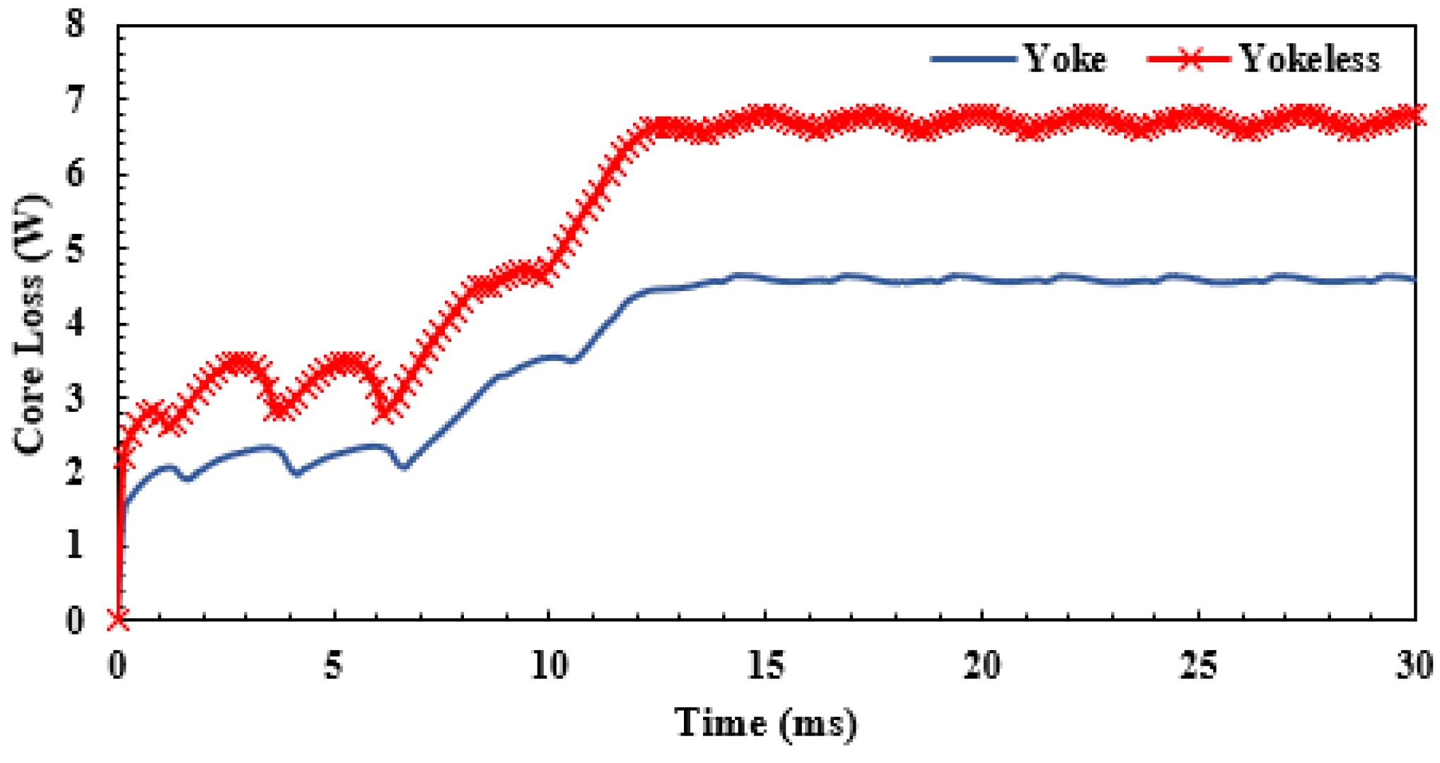
3.6. Core Loss and Efficiency

To calculate the efficiency of the two models, we neglected the mechanical loss and drive loss. The efficiency of both models was calculated using core loss in the iron core Piron and copper loss Pcu in the outer and inner stator windings. The core loss was obtained from the 2D-FEM analysis results, and the comparison between both models is shown in Figure 12.
The core loss of the yokeless rotor model was slightly higher as compared to the iron yoke rotor model due to the higher airgap flux density, as shown in Figure 6. The inner stator core volume was also increased in the yokeless rotor model, which contributed to the increased core loss. Both the machines had the same physical dimensions and the same stator configurations; the number of turns and the current density in both the stators were also the same. Therefore, the copper loss in both models should also be the same. The copper losses were calculated using the stator winding resistance as mentioned in Equation (5):
Pcu = 2 × m × Irms2 × Rph
where m denotes the number of phases, Irms is the RMS value of the phase current, and Rph is the phase resistance of stator winding. As shown in Table 2, the copper loss for both machines was the same, that is, 57.3 W.
On the basis of the above losses, we calculated the efficiency of both models as Equation (6):
η = Pout/(Pout + Pcu + Piron) × 100
The efficiency of the DARF model with an iron yoke rotor was 90.2%, whereas the efficiency of the yokeless rotor model was 89.3%, as shown in the comparison in Table 2. The overall comparison of both models is presented in Table 2.

4. Comparison between PMSM and PMVM

The comparison between single airgap PMSM and PMVM is presented in [11]. This section provides a comparison between dual airgap PMSM and PMVM. The dual airgap PMSM with iron yoke and the yokeless rotor was designed on the basis of the same dimensions and similar magnet volume as yokeless PMVM and compared with the yokeless PMVM model at similar operating conditions. The number of poles and winding configurations were kept constant for a fair comparison. Magnet strength is very important to consider in the yokeless model structure due to the small magnet thickness and high axial length. The bonded NdFeb magnet is more suitable for thin, small, and special-shaped structures due to its non-crystal material nature as compared to the sintered magnets. Therefore, bonded NdFeb magnets were used in this yokeless model. Figure 13 shows the different models of PMVM and PMSM utilized for comparison. Figure 13a shows the proposed DARF-PMVM model with the yokeless rotor, Figure 13b shows the DARF-PMSM with an iron yoke rotor with four poles, and Figure 13c shows the DARF-PMSM model with the yokeless rotor. The DARF-PMSM model with an iron yoke rotor was simulated with NdFeb sintered-type magnets, whereas the DARF-PMSM model with a yokeless rotor was simulated with NdFeb bonded-type as well as sintered-type magnets for comparison with the proposed PMVM model with a yokeless rotor.
All the models were simulated on the same no-load and load operating conditions at 400 rpm using 2D FEM analysis. The results are summarized in Table 3.
The results in Table 3 show that the PMVM model with a yokeless rotor performed better in terms of torque, torque ripple, and torque per magnet volume while using NdFeb bonded-type magnets as compared to the other three models. While comparing PMVM and PSMS yokeless rotor models with the same NdFeb bonded type magnets, we clearly found that the average torque in the PMSM model was 2.5 times less than the PMVM model with a similar topology. In contrast, in the case of PMSM models with iron yoke and a yokeless rotor with sintered type NdFeb magnets, the average torque was improved but the torque ripple was much higher than the PMVM model with a yokeless rotor.
Consequently, it can be concluded that the DARF-PMVM with the yokeless rotor can be a good replacement for the PMSM models, achieving comparable performance.

5. Experimental Validation

5.1. Experimental Setup

To verify the validity of the proposed design, we manufactured the prototype on the basis of the dimensions obtained from 2D FEM analysis results. The machine layout is shown in Figure 14. Each component of the prototype is shown in Figure 15 and the experimental setup for no-load analysis is shown in Figure 16. The detailed experimental results will be presented in the next version of this paper.
Figure 15a,c shows the outer and inner stators of the machine with conventional three-phase windings. Figure 15b shows the yokeless rotor structure with NdFeb bonded magnets and the non-magnetic stainless steel support made of SUS304 material. The non-magnetic support was very carefully designed to hold the magnets in position during the operation of the machine. The magnets were pasted on the non-magnetic sleeves placed inside the rotor for additional support. Due to the long length of the rotor magnets, each magnet was divided into four pieces of 25 mm each, which combined to make the total length of 100 mm.
The testbed in Figure 16a shows the prototype connected to the DC machine and oscilloscope. The DC machine works as a prime mover to provide a rated speed of 400 rpm. The DC machine was connected to the DC power supply. Figure 16b shows the connection winding connections for inner and outer stators. Both the stators were connected in series as shown in Figure 16b.

5.2. Experimental Results and Discussion

The prototype was tested under the no-load conditions by rotating with the help of a DC machine at the rated speed of 400 rpm, and the results were recorded. There was an error in the assembly of the manufactured model, which was confirmed by the phase shift in the back EMF of outer and inner stators. The machine was re-simulated with the same alignment settings as the prototype, and the back EMF results were compared. Figure 17 and Figure 18 show the comparison between no-load back EMF results obtained from the 2D-FEM simulations and the experiment results of the prototype for the outer and inner stator, respectively.
The RMS value of the back EMF of the outer stator obtained from 2D FEM was 14.9 V, which was similar to the value obtained from the prototype experiment, i.e., 14.7 V. The RMS value of the back EMF of the inner stator obtained from 2D FEM was 13.8 V, which was similar to the value obtained from the prototype experiment, i.e., 13.2 V. The detailed results of the prototype experiment and comparison between simulation and experiment results will be provided in the future version of this paper. The power factor of the PMVM model is generally low, and therefore the inverter rating would be a bit high. The power factor can be improved with certain optimization measures.

6. Conclusions

In this paper, a dual airgap PMVM with a yokeless rotor was proposed and compared with a conventional DARF model with an iron yoke rotor considering the same machine volume. The results revealed that the yokeless rotor model had significantly improved torque per magnet volume. The average torque and the torque density results were comparable due to effective flux linkage from the single layer of the magnets. Furthermore, the cogging torque and torque ripples were also significantly reduced because of the absence of an iron core in the rotor part. However, the efficiency of the yokeless rotor model was reduced by 1%, which can further be improved by the optimization process. The experimental results of the prototype for no-load back EMF also validated the 2D-FEM analysis results at similar operating conditions. Consequently, DARF-PMVM with the yokeless rotor can be a good replacement for the iron yoke rotor models, achieving a comparable performance and cost-effective solution with saving half of the magnet volume.

Author Contributions

Methodology, simulation, and writing—original draft preparation by M.R.S.; conceptualization, writing—review and editing by T.Y. and M.H.; project administration by J.-H.I.; funding acquisition, review, and formal analysis by J.H. All authors have read and agreed to the published version of the manuscript.

Funding

This work was supported by the Incheon National University under the research grant 2020-0424.

Institutional Review Board Statement

Not applicable.

Informed Consent Statement

Not applicable.

Data Availability Statement

Not applicable.

Conflicts of Interest

The authors declare no conflict of interest.

References

  1. Patterson, D.; Spee, R. The design and development of an axial flux permanent magnet brushless DC motor for wheel drive in a solar powered vehicle. IEEE Trans. Ind. Appl. 1995, 31, 1054–1061. [Google Scholar] [CrossRef]
  2. Niu, S.; Ho, S.L.; Fu, W.N.; Wang, L.L. Quantitative Comparison of Novel Vernier Permanent Magnet Machines. IEEE Trans. Magn. 2010, 46, 2032–2035. [Google Scholar] [CrossRef]
  3. Ishizaki, A.; Tanaka, T.; Takahashi, K.; Nishikata, S. Theory and Optimum Design of PM Vernier Motor. In Proceedings of the 1995 Seventh International Conference on Electrical Machines and Drives, Durham, UK, 11–13 September 1995; pp. 208–212. [Google Scholar]
  4. Gerber, S.; Wang, R.-J. Design and evaluation of a PM vernier machine. In Proceedings of the 2015 IEEE Energy Conversion Congress and Exposition (ECCE), Montreal, QC, Canada, 20–24 September 2015; pp. 5188–5194. [Google Scholar]
  5. Shentu, L.; Ma, Y.; Wang, J.; Zhou, J.; Zhou, L.; Qian, K. Design and Analysis of a Direct-Drive Permanent Magnet Vernier Motor for Electric Drilling Applications. In Proceedings of the 2018 21st International Conference on Electrical Machines and Systems (ICEMS), Jeju, Korea, 7–10 October 2018; pp. 81–86. [Google Scholar]
  6. Liu, Y.; Zhu, Z. Magnetic gearing effect in vernier permanent magnet synchronous machines. In Proceedings of the 2017 IEEE Energy Conversion Congress and Exposition (ECCE), Cincinnati, OH, USA, 1–5 October 2017; pp. 5025–5032. [Google Scholar]
  7. Kim, B.; Lipo, T.A. Operation and Design Principles of a PM Vernier Motor. IEEE Trans. Ind. Appl. 2014, 50, 3656–3663. [Google Scholar] [CrossRef]
  8. Zou, T.; Li, D.; Qu, R.; Jiang, D.; Li, J. Advanced High Torque Density PM Vernier Machine with Multiple Working Harmonics. IEEE Trans. Ind. Appl. 2017, 53, 5295–5304. [Google Scholar] [CrossRef]
  9. Li, J.; Chau, K.T.; Jiang, J.Z.; Liu, C.; Li, W. A New Efficient Permanent-Magnet Vernier Machine for Wind Power Generation. IEEE Trans. Magn. 2010, 46, 1475–1478. [Google Scholar] [CrossRef]
  10. Tlali, P.M.; Wang, R.-J.; Gerber, S. Comparison of PM Vernier and Conventional Synchronous 15 kW Wind Generators. In Proceedings of the 2018 XIII International Conference on Electrical Machines (ICEM), Alexandroupoli, Greece, 3–6 September 2018; pp. 2065–2071. [Google Scholar]
  11. Zhao, F.; Lipo, T.A.; Kwon, B.I. Magnet flux focusing design of double stator permanent magnet Vernier machine. In Proceedings of the Conference on the Computation of Electromagnetic Fields (Compumag 2013), Budapest, Hungary, 30 June–4 July 2013; pp. 1–4. [Google Scholar]
  12. Kim, B.; Lipo, T.A. Analysis of a PM Vernier Motor with Spoke Structure. In Proceedings of the IEEE Energy Conversion Congress and Exposition, Pittsburgh, PA, USA, 14–18 September 2014; pp. 5034–5041. [Google Scholar]
  13. Zhao, F.; Lipo, T.A.; Kwon, B.-I. A Novel Dual-Stator Axial-Flux Spoke-Type Permanent Magnet Vernier Machine for Direct-Drive Applications. IEEE Trans. Magn. 2014, 50, 1–4. [Google Scholar] [CrossRef]
  14. Du, Z.S.; Lipo, T.A. High torque density ferrite permanent magnet vernier motor analysis and design with demagnetization consideration. In Proceedings of the 2015 IEEE Energy Conversion Congress and Exposition (ECCE), Montreal, QC, Canada, 20–24 September 2015; pp. 6082–6089. [Google Scholar]
  15. Du, Z.S.; Lipo, T.A. Torque Performance Comparison Between a Ferrite Magnet Vernier Motor and an Industrial Interior Permanent Magnet Machine. IEEE Trans. Ind. Appl. 2017, 53, 2088–2097. [Google Scholar] [CrossRef]
  16. Li, D.; Qu, R.; Li, J.; Xu, W. Consequent-Pole Toroidal-Winding Outer-Rotor Vernier Permanent-Magnet Machines. IEEE Trans. Ind. Appl. 2015, 51, 4470–4481. [Google Scholar] [CrossRef]
  17. Xie, K.; Li, D.; Qu, R.; Gao, Y. A Novel Permanent Magnet Vernier Machine with Halbach Array Magnets in Stator Slot Opening. IEEE Trans. Magn. 2017, 53, 1–5. [Google Scholar] [CrossRef]
  18. Wei, L.; Nakamura, T. A Novel Dual-Stator Hybrid Excited Permanent Magnet Vernier Machine with Halbach-Array PMs. IEEE Trans. Magn. 2021, 57, 1–5. [Google Scholar] [CrossRef]
  19. Baloch, N.; Kwon, B.; Gao, Y. Low Cost High Torque Density Dual-Stator Permanent Magnet Vernier Machine. In Proceedings of the 2018 IEEE International Magnetics Conference (INTERMAG), Singapore, 23–27 April 2018; p. 1. [Google Scholar]
  20. Gao, Y.; Qu, R.; Li, D.; Fang, H.; Li, J.; Kong, W. A Novel Dual-Stator Vernier Permanent Magnet Machine. IEEE Trans. Magn. 2017, 53, 1–5. [Google Scholar] [CrossRef]
  21. Chai, F.; Cui, S.; Cheng, S. Performance analysis of double-stator starter generator for the hybrid electric vehicle. IEEE Trans. Magn. 2005, 41, 484–487. [Google Scholar] [CrossRef]
  22. Huang, X.; Zhang, K.; Wu, L.; Fang, Y.; Lu, Q. Design of a Dual-Stator Superconducting Permanent Magnet Wind Power Generator with Different Rotor Configuration. IEEE Trans. Magn. 2017, 53, 1. [Google Scholar] [CrossRef]
  23. Raminosoa, T.; Gerada, C.; Othman, N.; Lillo, L. Rotor losses in fault-tolerant permanent magnet synchronous machines. IET Electr. Power Appl. 2011, 5, 75. [Google Scholar] [CrossRef] [Green Version]
  24. Yazdan, T.; Atiq, S.; Kwon, B.-I.; Baloch, N.; Kwon, J.-W. Two Phase Dual-Stator Axial-Flux PM BLDC Motor With Ironless Rotor Using Only-Pull Drive Technique. IEEE Access 2019, 7, 82144–82153. [Google Scholar] [CrossRef]
  25. Dumas, F.; Matt, D.; Jac, J.; Enrici, P. A design approach for an axial-flux permanent magnet motor. In Proceedings of the XIX International Conference on Electrical Machines—ICEM 2010, Rome, Italy, 6–8 September 2010; pp. 1–6. [Google Scholar]
Figure 1. Dual airgap radial type PMVM topologies: (a) with iron yoke rotor, (b) without iron yoke (yokeless) rotor.
Energies 14 02311 g001
Figure 2. Mesh layout for 2D FEM analysis.
Energies 14 02311 g002
Figure 3. Flux path for DARF-PMVM: (a) with iron yoke rotor, (b) without iron yoke (yokeless) rotor.
Energies 14 02311 g003
Figure 4. Reluctances in the flux path of DARF-PMVM: (a) with iron yoke rotor, (b) without iron yoke (yokeless) rotor.
Energies 14 02311 g004
Figure 5. Mutual inductance comparison in DARF-PMVM.
Energies 14 02311 g005
Figure 6. Flux densities comparison in DARF-PMVM at no-load: (a) with iron yoke rotor, (b) without iron yoke (yokeless) rotor.
Energies 14 02311 g006
Figure 7. Flux densities comparison in DARF-PMVM at load: (a) with iron yoke rotor, (b) without iron yoke (yokeless) rotor.
Energies 14 02311 g007
Figure 8. Flux linkage comparison in DARF-PMVM: (a) with iron yoke rotor, (b) without iron yoke (yokeless) rotor.
Energies 14 02311 g008
Figure 9. Back EMF comparison in DARF-PMVM: (a) with iron yoke rotor, (b) without iron yoke (yokeless) rotor.
Energies 14 02311 g009
Figure 10. Cogging torque comparison in DARF-PMVM: (a) iron rotor yoke model, (b) yokeless rotor model.
Energies 14 02311 g010
Figure 11. Electromagnetic torque comparison in DARF-PMVM.
Energies 14 02311 g011
Figure 12. Core loss comparison in DARF-PMVM.
Energies 14 02311 g012
Figure 13. DARF PM machines: (a) PMVM yokeless, (b) PMSM with iron yoke rotor, (c) PMSM with yokeless rotor.
Energies 14 02311 g013
Figure 14. The layout of the PMVM model with a yokeless rotor.
Energies 14 02311 g014
Figure 15. Prototype of proposed machine: (a) outer stator, (b) yokeless rotor, (c) inner stator.
Energies 14 02311 g015
Figure 16. Experimental setup (a) Testbed for the yokeless rotor DARF PMVM experiment; (b) winding connections.
Energies 14 02311 g016
Figure 17. Back EMF comparison-outer stator: (a) 2D-FEM simulation, (b) prototype experiment.
Energies 14 02311 g017
Figure 18. Back EMF comparison-inner stator: (a) 2D-FEM simulation, (b) prototype experiment.
Energies 14 02311 g018
Table 1. Specifications of DARF-PMVM models.
ParameterUnitsValues
With Iron Yoke RotorYokeless
Rotor
Active outer diametermm120
Active inner diametermm30
Outer diameter of the inner statormm68.681.1
Active axial lengthmm100
Number of rotor pole pairs-10
Number of stator slots-12
Number of stator poles-4
Length of air gapmm0.7
Magnet type-NdFeb bonded (Br = 0.5 T, Hc = −304 kA/m)
Rotor core material-Steel S50PN470Non-Mag. SUS304
Volume of magnetL0.1050.053
Machine volumeL1.06
Number of turns per slot-70
Slot fill factor (outer/inner stator)%50/6050/50
Rated rotational speedrpm400
Max. phase currentArms4.7
Table 2. Performance comparison of DARF-PMVM with iron yoke and yokeless rotor models.
ParameterUnitsValues
With Iron Yoke RotorYokeless
Rotor
Back EMF (inner/outer)V22.21/17.3819.45/17.52
Cogging torque pk2pkNm0.7730.089
Max. phase currentArms4.7
Torque ripple%5.92.5
Mutual inductancemH0.0276.95
Average torqueNm13.4312.57
Machine volumeL1.06
Magnet volumeL0.1050.053
Torque densityNm/L12.6711.86
Torque per magnet volumeNm/L127.6238.9
Copper lossW57.3
Core lossW3.275.53
Total lossW60.662.9
Efficiency%90.389.2
Table 3. Performance comparison of DARF-PMVM with iron yoke and yokeless rotor models.
ParameterUnitsValues
PMVM
(Yokeless)
PMSM
(Yokeless)
PMSM
(Yoke)
PMSM
(Yokeless)
Magnet type-NdFeb BondedNdFeb Sintered
Back EMF-36.915.2143.2438.7
Average torqueNm12.575.010.4711.9
Torque ripple%2.57845118
Magnet volumeNm/L0.05
Torque per magnet volumeNm/L238.996.2201.3228.8
Publisher’s Note: MDPI stays neutral with regard to jurisdictional claims in published maps and institutional affiliations.

