Review

Recent Research Progress in Hybrid Photovoltaic–Regenerative Hydrogen Fuel Cell Microgrid Systems

by
Alexandros Arsalis
1,*,
George E. Georghiou
1,2 and
Panos Papanastasiou
1,3
1
FOSS Research Centre for Sustainable Energy, University of Cyprus, Panepistimiou 1, Nicosia 1678, Cyprus
2
Department of Electrical and Computer Engineering, University of Cyprus, Kallipoleos 75, Nicosia 1678, Cyprus
3
Department of Civil and Environmental Engineering, University of Cyprus, Kallipoleos 75, Nicosia 1678, Cyprus
*
Author to whom correspondence should be addressed.
Energies 2022, 15(10), 3512; https://doi.org/10.3390/en15103512
Submission received: 12 April 2022 / Revised: 5 May 2022 / Accepted: 9 May 2022 / Published: 11 May 2022
(This article belongs to the Special Issue Design, Modeling, and Optimization of Novel Fuel Cell Systems)

Abstract

:
Hybrid photovoltaic–regenerative hydrogen fuel cell (PV-RHFC) microgrid systems are considered to have a high future potential in the effort to increase the renewable energy share in the form of solar PV technology with hydrogen generation, storage, and reutilization. The current study provides a comprehensive review of the recent research progress of hybrid PV-RHFC microgrid systems to extract conclusions on their characteristics and future prospects. The different components that can be integrated (PV modules, electrolyzer and fuel cell stacks, energy storage units, power electronics, and controllers) are analyzed in terms of available technology options. The main modeling and optimization methods, and control strategies are discussed. Additionally, various application options are provided, which differentiate in terms of scale, purpose, and further integration with other power generating and energy storage technologies. Finally, critical analysis and discussion of hybrid PV-RHFC microgrid systems were conducted based on their current status. Overall, the commercialization of hybrid PV-RHFC microgrid systems requires a significant drop in the RHFC subsystem capital cost. In addition, it will be necessary to produce complete hybrid PV-RHFC microgrid systems with integrated energy management control capabilities to avoid operational issues and ensure flexibility and reliability of the energy flow in relation to supply, storage, and demand.

1. Introduction

The continuously increasing cost of fossil fuels, along with the requirement to decarbonize the energy infrastructure, create the need for an escalation of power generation from renewable energy sources (RES) [1]. However, RES-based power generation is intermittent and requires effective and practical energy storage [2]. Due to this intermittent nature, the RES-generated electricity is difficult to be utilized continuously and stably, which creates spatial and temporal gaps between the available power and the power consumed by the end-users [3]. To help resolve this issue, the integration of energy storage with RES-based power generators may greatly improve the utilization rate and stability of RES-based systems. Decentralized, distributed power generation systems have been identified as a possible solution for the increase of RES-based power production [4,5,6]. One typical example of such systems is microgrids, which create the possibility of developing smaller and flexible power grids, which can operate either in complete autonomy, or even remain connected to larger central power grids, and exchange power as needed [7]. Microgrids also offer higher efficiency, better utilization of resources, and operate with minimum carbon emissions [8,9,10]. Additionally, they offer the possibility of connecting and combining multiple loads, such as different types of buildings (residential, commercial, public, and industrial), and electric vehicles [11,12,13]. They can also provide higher flexibility and reduce carbon emissions in comparison to conventional auxiliary power units (APUs) for remote applications [14,15,16].
The maximization of RES generation is directly related to the integration of efficient energy storage into the microgrid system, and therefore different types of energy storage must be coupled to the microgrid to maximize self-sufficiency and self-consumption [17,18,19]. RES-based microgrid systems also require efficient and flexible energy storage to increase their capacity and arbitrage [20]. Apart from storage of electrical energy within batteries, which are primarily suitable for short-term storage, hydrogen generation-storage-and-reutilization can be used to achieve long-term storage [21]. The various components in the microgrid need to be coupled in an optimum configuration to improve power-sharing in the buildings, and minimize the capacities of the integrated components, which in turn help minimize the total capital cost of the overall microgrid system [22]. Specifically, for a regenerative hydrogen fuel cell (RHFC) subsystem, an intelligent operational scheme for the electrolyzer, the fuel cell stacks, and the hydrogen storage units (HSUs) must be applied [23]. Additionally, fuel cell operation generates heat which can be recovered to fully, or partly, cover the heating load (space heating, domestic hot water, etc.) of the serviced buildings [24]. Hydrogen availability in the local microgrid also provides hydrogen fueling for fuel cell electric vehicles (FCEVs) [25]. This can also help reduce well-to-wheel emissions in the transport system [26]. A photovoltaic (PV)-powered microgrid with coupled hydrogen generation, storage, and, reutilization capabilities can offer significant advantages, including avoidance of congestion of central power grids, reduced generation of electricity in centralized power stations, and increase of the penetration of RES-generated power in the energy network [27].
The motivation of this work is to critically analyze hybrid PV-RHFC microgrid systems, which are considered to have a high future potential in the effort to increase RES share in the form of solar PV technology with hydrogen generation, storage, and reutilization. This technology has seen a growing interest in recent years as evidenced by the increasing publication activity in the open literature. Therefore, there is a need to review this research progress and extract conclusions on the characteristics and future prospects of hybrid PV-RHFC microgrid systems. In Section 2, the various components (PV modules, electrolyzer, and fuel cell stacks, energy storage units, power electronics, and controllers) that are included in typical hybrid PV-RHFC system configurations are analyzed in detail to show the coupling options for different available technologies. In Section 3, the main modeling and optimization methods, and control strategies for hybrid PV-RHFC microgrid systems are discussed. In Section 4, the various application possibilities of hybrid PV-RHFC microgrid systems are provided (nanogrids, microgrids, stationary, transport, combined applications, and further integration with other power generating and energy storage technologies). In Section 5, critical analysis and discussion of hybrid PV-RHFC microgrid systems were conducted to identify the current status of the technology and extract conclusions on the existing problems that need to be resolved in order to increase their future commercialization potential.

2. Integration of Components in Hybrid PV-RHFC Microgrid Systems

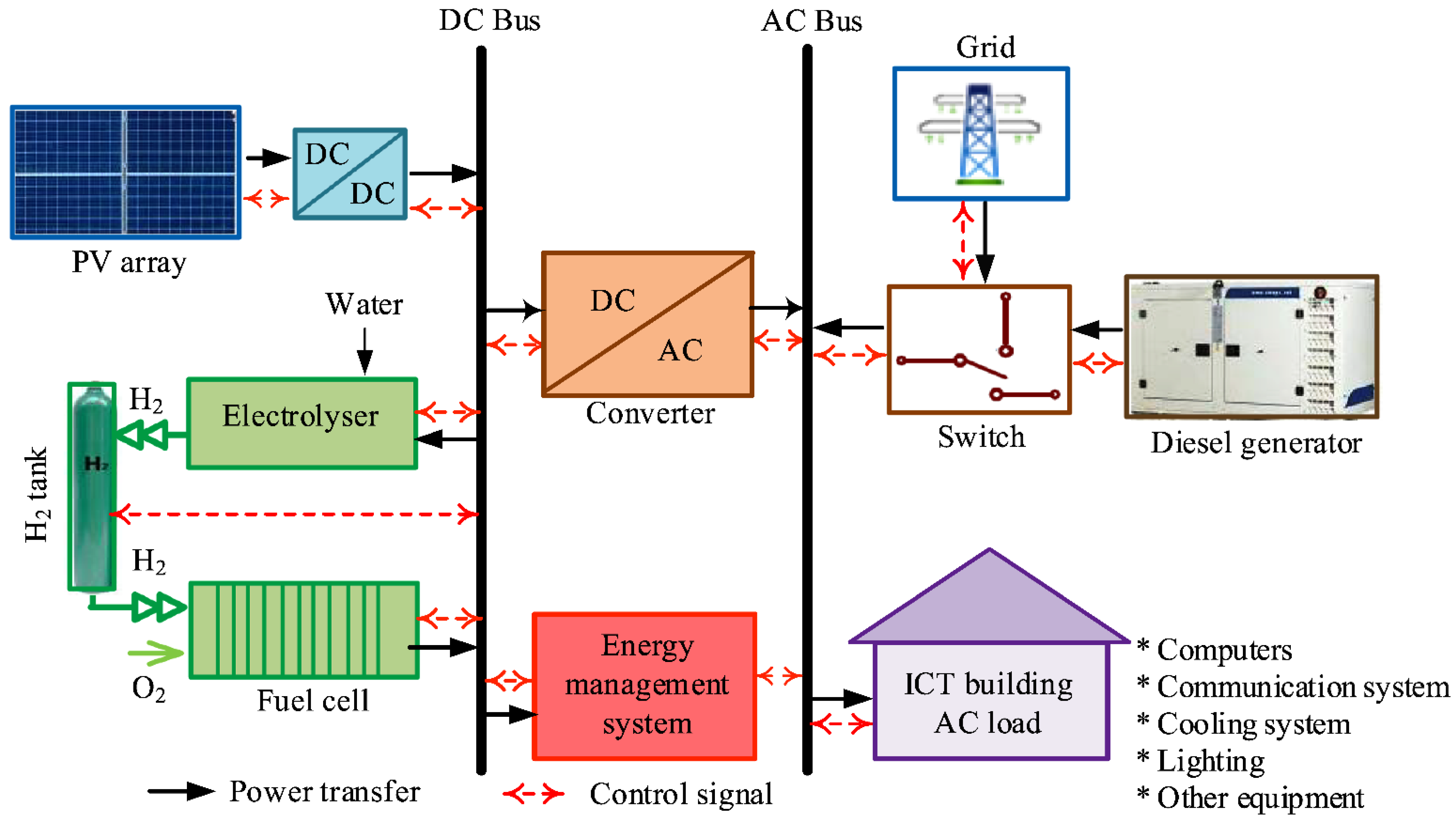
The integrated components in a hybrid PV-RHFC microgrid system consist of PV modules, electrolyzer and fuel cell stacks, energy storage units, and auxiliary components (power electronics, etc.). In Figure 1, the main and some of the auxiliary components are shown.

2.1. PV Modules

The PV modules directly generate electricity from solar radiation and may include series and parallel-connected solar cells in order to obtain the required power output [29]. The most typical PV types are monocrystalline and polycrystalline technologies [30]. The PV panels can be placed on adjustable racks where the tilt angle can be varied in different directions [7]. Ideally, in microgrid systems, PV modules are placed on the roofs of the serviced buildings, in an effort to create “virtual power stations”, which have no additional space requirements, as in the case of centralized power stations [31]. However, when extra power generating capacity is required, PV modules can be installed in so-called PV parks (or PV farms) [32].

2.2. Electrolyzer and Fuel Cell Stacks

The main electrolyzer technologies are alkaline electrolyzer cells (AECs), proton exchange membrane electrolyzer cells (PEMECs), and solid oxide electrolyzer cells (SOECs); while the main fuel cell technologies are proton exchange membrane fuel cells (PEMFCs), and solid oxide fuel cells (SOFCs) [33]. For electrolysis, AEC is the most mature technology with the highest lifetime, but PEMEC and SOEC technologies are more promising since they are capable of operating at higher efficiencies [20]. For fuel cells, PEMFCs are generally more suitable than SOFC stacks for small-scale, decentralized applications, because they operate at lower temperatures, and when the fuel is pure hydrogen, they do not have any poisoning issues [34]. However, the durability of electrolyzer and fuel cell stacks is highly dependent on the operating conditions, including load fluctuations, start-up, and shut-down frequencies, and idling conditions; these play an important role in the lifetime and possible premature degradation of the stacks [30]. Proper integration and operating strategies must be implemented, since dynamic load fluctuations and frequent start-ups and shut-downs are unavoidable for microgrids, because of the variable nature of solar PV technology (which is the power source of electrolyzer stacks) [35].

2.3. Energy Storage Units

Multiple types of energy storage are usually required to be coupled in hybrid PV-RHFC microgrid systems. The integration and operation of multiple types of energy storage technologies require effective dimensioning of the capacities of the energy storage units, with the application of relevant optimization strategies [17]. Batteries are not very flexible in terms of capacity and operation for a PV-based microgrid system, because they have to operate within a limited state of charge to avoid early lifetime degradation. For these reasons, the battery is used only for short-term storage and the RHFC is needed for larger-scale, long-term storage.

2.3.1. Batteries

For short-term storage, aiming at covering the frequent instantaneous power peaks, batteries are usually used. Typically, commercially-available battery types are used, which have well-proven capabilities and come at a low cost, such as lead-acid and lithium-ion batteries [27,29,36]. Redox flow batteries are suitable for long-term storage; however, they have a lower round-trip efficiency and significantly lower power density than lithium-ion batteries [37,38].

2.3.2. Hydrogen Storage

Hydrogen storage in HSUs can be utilized in the microgrid to improve its long-term storage capabilities, since it offers negligible self-discharge rates [20]. Another important advantage of hydrogen storage is the very high energy density of hydrogen, which is highly desirable in vehicular applications, and in general in applications where space restrictions are unavoidable [14]. The most practical hydrogen storage technology is compressed hydrogen, due to its technological maturity and low capital cost [29]. However, other hydrogen storage technologies have emerged in recent years that do not require high pressurization, such as metal hydrides [39,40]. The RHFC subsystem requires several auxiliary components; some of them depend on the type of the HSU. In the case of compressed hydrogen technology, a hydrogen compressor is needed before storing [29]; while in the case of metal hydride technology, a cooling/heating system is needed [27]. A water purifier is also needed to purify tap water before usage in the electrolyzer [26]. Specifically, electrolyzers require distilled water with very low conductivity (typically <2 μS/cm) to maintain their prescribed manufacturer lifetime estimates [41].

2.4. Power Electronics

Power electronics include DC/DC and DC/AC converters, DC, and AC buses, which allow the microgrid to operate in both DC and AC modes, as needed [27]. The generated DC is typically converted to AC with a DC/AC inverter to satisfy the electrical loads of a building [17]. In an AC/DC microgrid, an internal DC link is connected on the AC side to connect the power generators and energy storage systems with a grid-side converter to constantly regulate bus voltage and frequency [29]. In addition, for building applications, a DC bus must be integrated between the hybrid PV-RHFC microgrid system and the electrical load of the building [42]. In the case of vehicle-to-grid applications, and since the output of an electric vehicle is DC power, this DC output must be converted to AC power with a DC/AC inverter installed in the conductive charging station [25]. An AC bus can be used to integrate the PV modules, battery storage units, electrolyzer, and auxiliary components with power electronics, in order to control the power flows [11].

2.5. Controllers

An energy management system (EMS) is integrated into the total energy system to effectively manage all the coupled components (PV power generator, energy storage units, loads, and auxiliaries) [36]. It is used to provide stability to the DC bus voltage, and balance supply vs. demand, while minimizing the interactions with the central power network [27]. A remote terminal unit (RTU) is a data concentrator and communication gateway microprocessor-controlled electronic device, which interacts directly with the power network; it also provides information data for critical parameters, such as current, voltage, and temperature [23,43]. This also allows monitoring of the actual components to a SCADA (supervisory control and data acquisition) system, which is based on an architecture server/client scheme, with the transmission of telemetry data [36].

3. Development, Operation, and Control of Hybrid PV-RHFC Microgrid Systems

3.1. Modeling and Optimization Methods

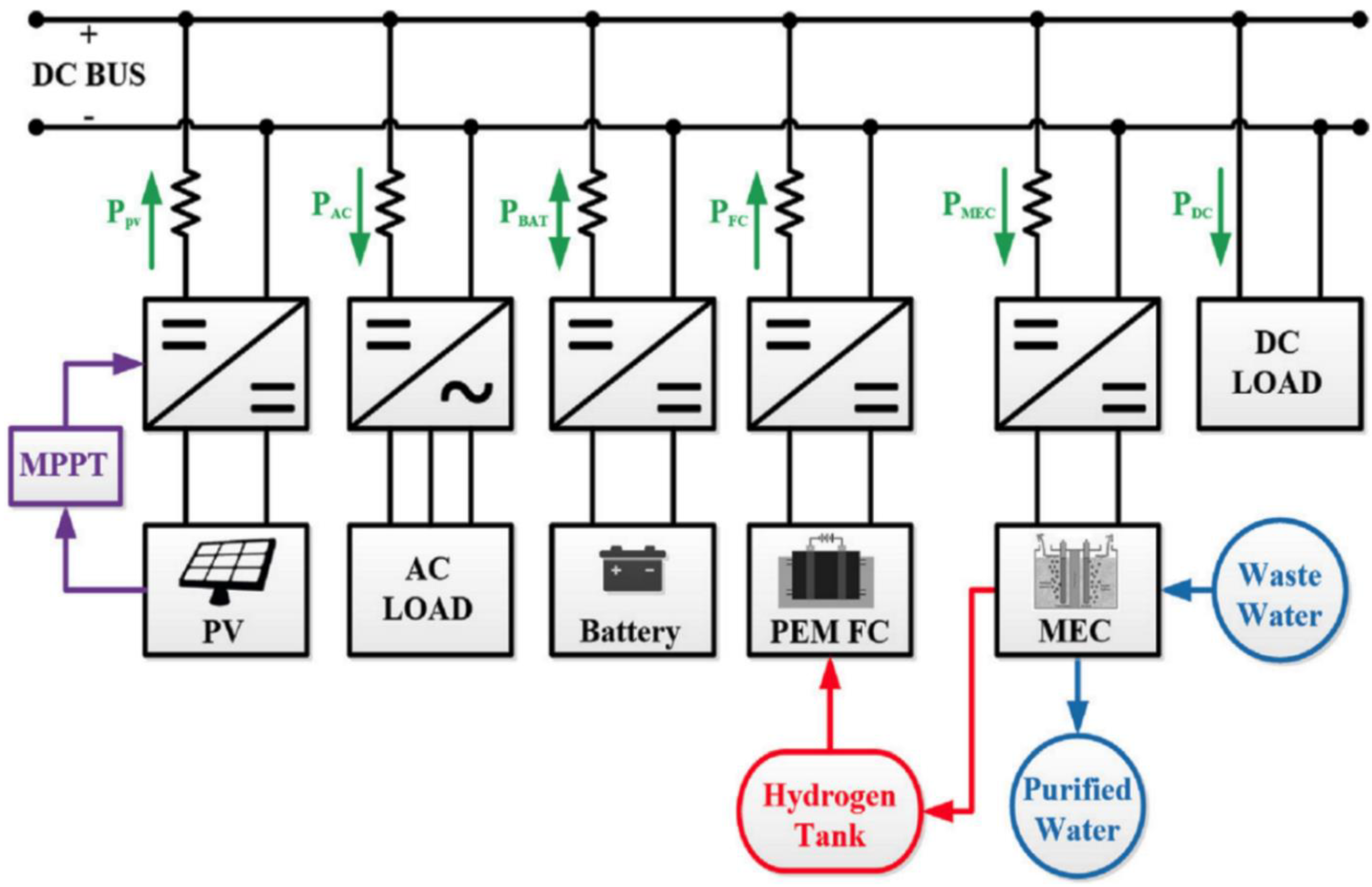
The typical modeling of a microgrid system starts with the modeling of each individual component. All component/subsystem models are then integrated into the total microgrid system model [27]. A typical software to model hybrid PV-RHFC microgrid systems is MATLAB-SimulinkTM. Abulanwar et al. [29] considered a fixed time step (2 μs) for transient operation during different faults for a standalone hybrid AC/DC microgrid system (see Figure 2). The proposed strategy was formulated to fulfil the load profile during normal conditions by splitting demand between the various power generators and energy storage units. In addition, hydrogen management was optimized to prolong lifetime, and microgrid stability was enhanced to withstand low power generation occurrences. Alavi et al. [26] developed a “car as power plant” microgrid system model (see Figure 3) where the individual models were converted into mixed logical dynamical models to describe the response of the system with both continuous and discrete variables. The purpose of the control system was to minimize the operating cost, by modeling FCEV characteristics along with their traveling schedules by implementing a min-max predictive control scheme. Niknejad et al. [44] developed an AC/DC microgrid system model (see Figure 4) in Simulink to evaluate the system power balance behavior for different scenarios. A dynamic control strategy was implemented to optimize power management during standalone operation. The simulation results were validated with an experimental hardware-in-the-loop setup.
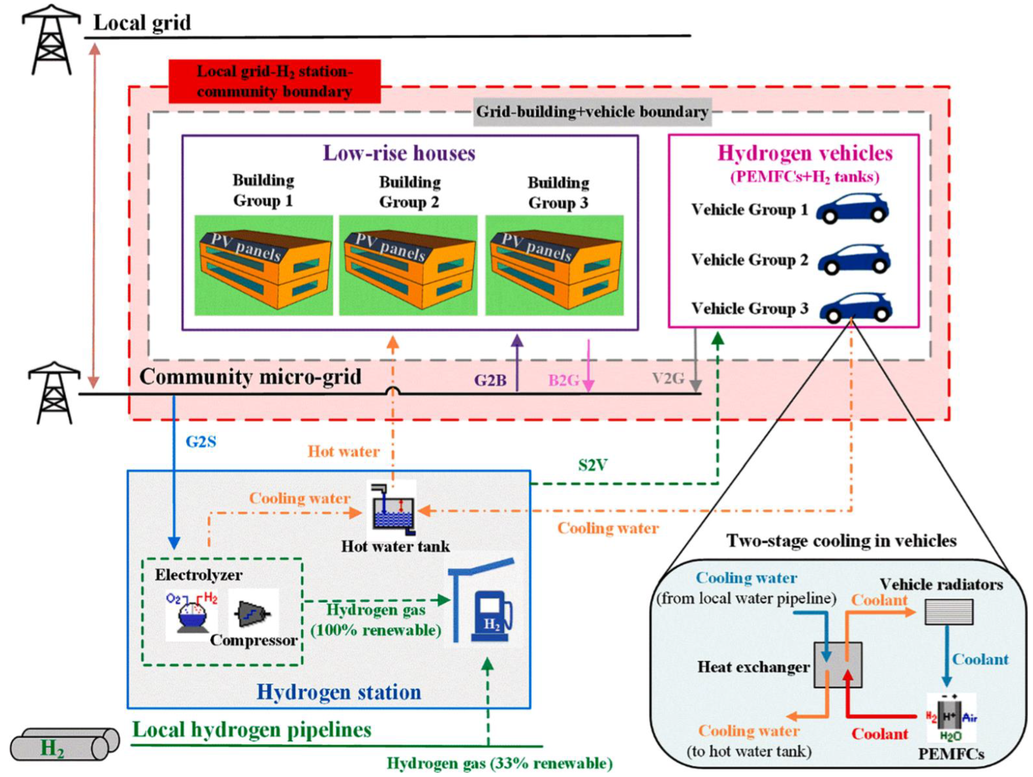
He et al. [21] developed a transient microgrid system model in TRNSYS for application in a community with low-rise households, rooftop PVs, FCEVs, and a hydrogen station (see Figure 5). The authors proposed various energy management strategies to improve technoeconomic performance and system flexibility, and a parametric optimization was conducted to intelligently control charging/discharging, and to balance grid stability and energy cost. Jaramillo et al. [45] designed and optimized a grid-connected microgrid system in MATLAB using the built-in optimization toolbox for the operational scheduling of the components, where the objective function aimed at the minimization of the costs related to environmental impact. The authors applied a multi-objective mixed-integer linear programming model, while the ramp-up constraints of the electrolyzer were modeled explicitly. The objective function included operating costs, environmental factors, and peak power costs to reduce the overall peak load. Mah et al. [17] applied a particle swarm optimization methodology within the MATLAB optimization toolbox, where the objective function was to minimize the annual cost of the microgrid system by varying the key component capacities (i.e., PV panels, battery, and HSU). Two energy management strategies were proposed: the first one prioritized the fulfillment of the load profile with PV-generated electricity, and then excess energy was stored in the energy storage units; the second one gave priority to hydrogen generation and storage in HSUs to satisfy the hydrogen loads.
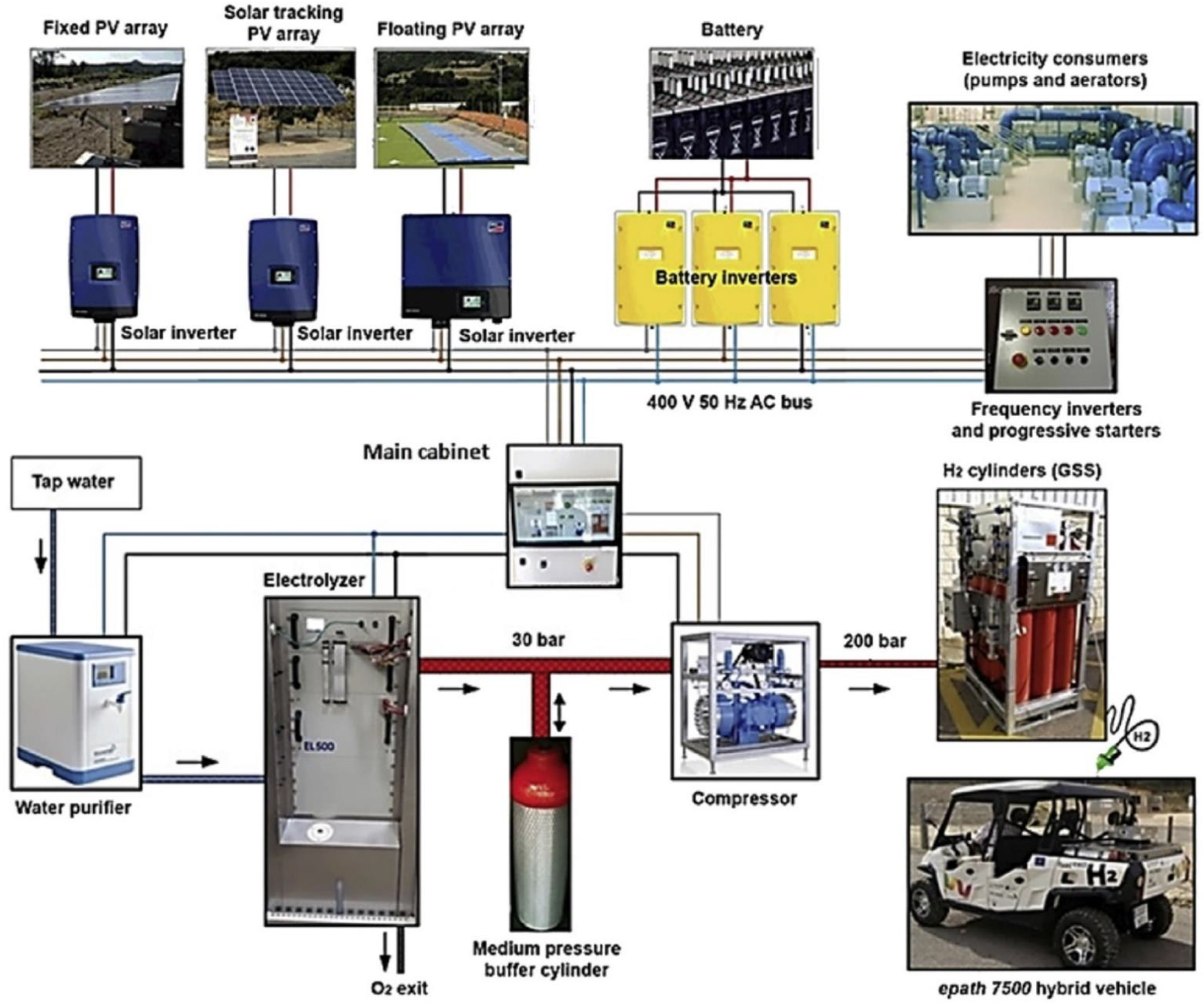
There are also several modeling software packages that include optimization tools and can be applied for microgrid system modeling, such as the hybrid optimization model for electric renewables (HOMER), and the improved hybrid optimization by the genetic algorithm (iHOGA) [41]. HOMER allows for the inclusion of operating conditions with uncertainty considerations to improve the robustness of the model and minimize economic risks [36,39,40]. Castellanos et al. [22] developed a system model using HOMER, which was sized by varying the capacity of the individual components (storage, power output) with several permutations to meet the needed load requirements. The authors considered seven scenarios, with various power generation options. Chen et al. [46] developed a microgrid system with onsite hydrogen refueling stations (see Figure 6) in HOMER targeting the determination of the optimal component sizes. The sizing of the main components was optimized with a three-stage procedure (simulation, optimization, and sensitivity analysis), while the purpose of the objective function was the minimization of the total net present cost. Murthy et al. [47] developed a microgrid system model in HOMER, which targeted the optimization of component capacities (PVs, battery, and electrolyzer) in terms of quality indicators (excess PV-generated electricity, and unsatisfied electric, hydrogen, and thermal loads) to meet the load demand. Carroquino et al. [41] developed a power-to-gas PV-RHFC microgrid system with batteries, and FCEVs (see Figure 7) in iHOGA, aiming at the optimization of the design and performance of the system in terms of efficiency and reliability, where a battery aging model was incorporated to optimize the hybrid system.
Mukherjee et al. [25] applied a four-phase approach to design a microgrid system model in GAMS (see Figure 8). In the preliminary phase, various data were gathered (land space availability for the infrastructure of the microgrid, electricity demand and costs, climatic conditions, and hydrogen demand). In the pre-processing phase, various RES and RHFC technologies were considered, on the basis of their technoeconomic feasibility. In the design phase, the technoeconomic model of each technology was simulated to find the optimal design and operation of the total system. The system was optimized based on the simulated model of the technologies and preprocessing data, including microgrid energy demand, and market information. In the post-processing phase, an economic assessment of the design configuration was conducted based on the model output. Nadal et al. [42] developed a microgrid system model using the Odyssey platform, which allows design optimization and energy management to minimize energy cost and maximize load fulfillment on an annual basis. The research team proposed two different approaches to resolve design uncertainties and optimize decision-making: (a) sensitivity analysis approach, which considers the uncertainties after system optimization; and (b) robust optimization, which adapts a Monte Carlo simulation into a genetic algorithm-based scheme. In Table 1, the aforementioned modeling and optimization methods for hybrid PV-RHFC microgrid systems are summarized.

3.2. Application of Control Strategies

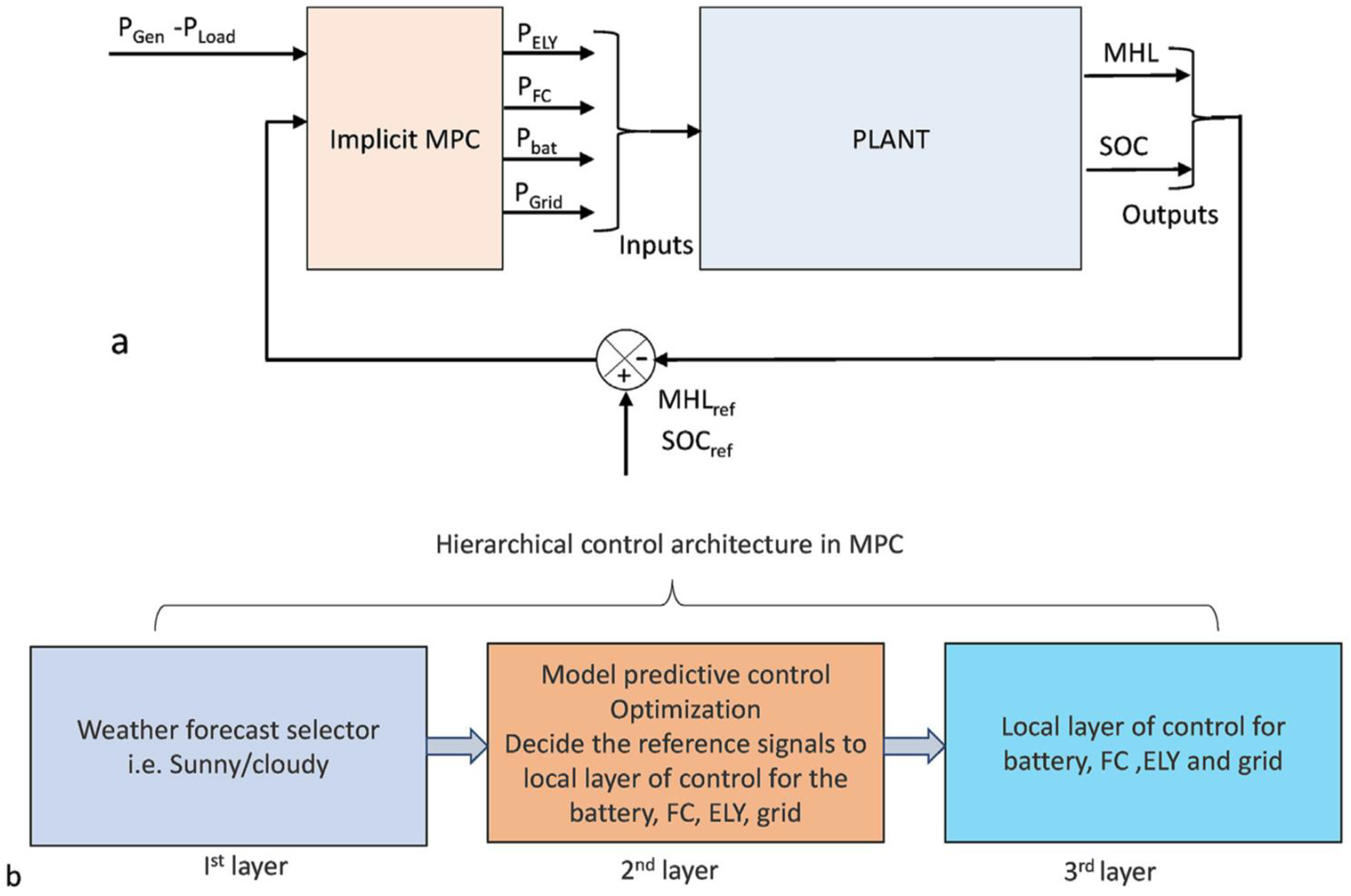
The control of a hybrid PV-RHFC microgrid system requires the application of advanced methodologies, because of the high number of components and multiple modes of operation, which typically result in nonlinear systems. Moreover, load variations can create grid impedance fluctuations, which must be treated with effective control strategies. Such advanced strategies aim for the optimal management of the microgrid, facilitating maximization of RES penetration to the energy system, which also requires utilization of multiple types of energy storage. Specifically, the energy management strategy provides effective control and ensures a smooth operation of the fuel cell and electrolyzer stacks; while additionally, it provides the balancing of supply vs. demand, efficient operation, reliability, and resiliency (by regulating the power variation events for the stacks at dynamic operation) [48]. Various control strategies have been considered for microgrid integration, such as model predictive control (see Figure 9), hysteresis band control strategy, equivalent consumption and minimization strategy, and state machine [39]. Power production scheduling and model predictive control must be combined to achieve optimal long-term and short-term planning [49]. In more complex, large-scale, microgrid systems, advanced power management techniques are needed to strengthen power flexibility and grid stability [21]. For a hybrid AC/DC microgrid, an adaptive control strategy can be developed to enable the fulfillment of the load demand via power-sharing between the integrated power generators and energy storage units; while a specific hydrogen management pattern is applied to ensure maximum lifetime; and also, operation at the lowest cost [29]. The latter is usually the most important criterion in the design of the control system, since the minimization of operating costs (i.e., the cost of electricity) will affect the amount of power exchange between the microgrid and the central power grid (or macrogrid) [26].
Several research efforts have been reported in recent publications, which aimed at the development of novel control strategies to optimize performance, including energy efficiency and cost optimization. Xie et al. [48] developed a greedy energy management strategy, based on model predictive control for a power-to-hydrogen-to-power system, which includes a day-ahead plan and an intra-day dispatch method. It consists of two stages: (a) the planning stage, where the aim is to find the power of every storage unit for a certain time period, and (b) the dispatching stage, where the energy dispatch is subject to the scheduled plan and the operational constraints. De Oliveira–Assis et al. [50] developed a novel EMS with a biogeography-based optimization algorithm for a hybrid BEV (Battery Electric Vehicle) charging station to control the energy flow between the components, in an effort to optimize hydrogen generation and consumption (see Figure 10). Garcia et al. [51] developed an EMS for a hybrid PV-wind turbine-RHFC microgrid system to optimize the economic performance of the system, by relating the expected lifetime of the energy sources of the components to their manufacturing costs. Konstantinopoulos et al. [52] developed an EMS with reserve scheduling to optimally operate a 17-bus low voltage, grid-tied, hybrid PV–wind turbine–RHFC microgrid system, where the resulting deviations due to RES intermittency were fulfilled by the RHFC subsystem to reduce the scheduled energy demand. Li et al. [53] developed an EMS for a hybrid PV–wind turbine–RHFC DC microgrid system operating in island mode, using a quasi-proportional resonance to distribute power to each power generator. In Table 2, the aforementioned control strategies for hybrid PV-RHFC microgrid systems are summarized.

4. Applications of Hybrid PV-RHFC Microgrid Systems

A hybrid PV-RHFC microgrid system can be designed to serve multiple types of buildings (i.e., residential, public, commercial, and industrial). Therefore, the total load profile will be the sum of the individual load profiles, which vary depending on their size, number of occupants, and schedule of occupancy [21]. A hybrid PV-RHFC microgrid system can also serve multiple purposes, i.e., charge BEVs and/or fuel FCEVs. Additionally, hybrid PV-RHFC microgrid systems may be integrated with other power generating and energy storage technologies.

4.1. Nanogrid Systems

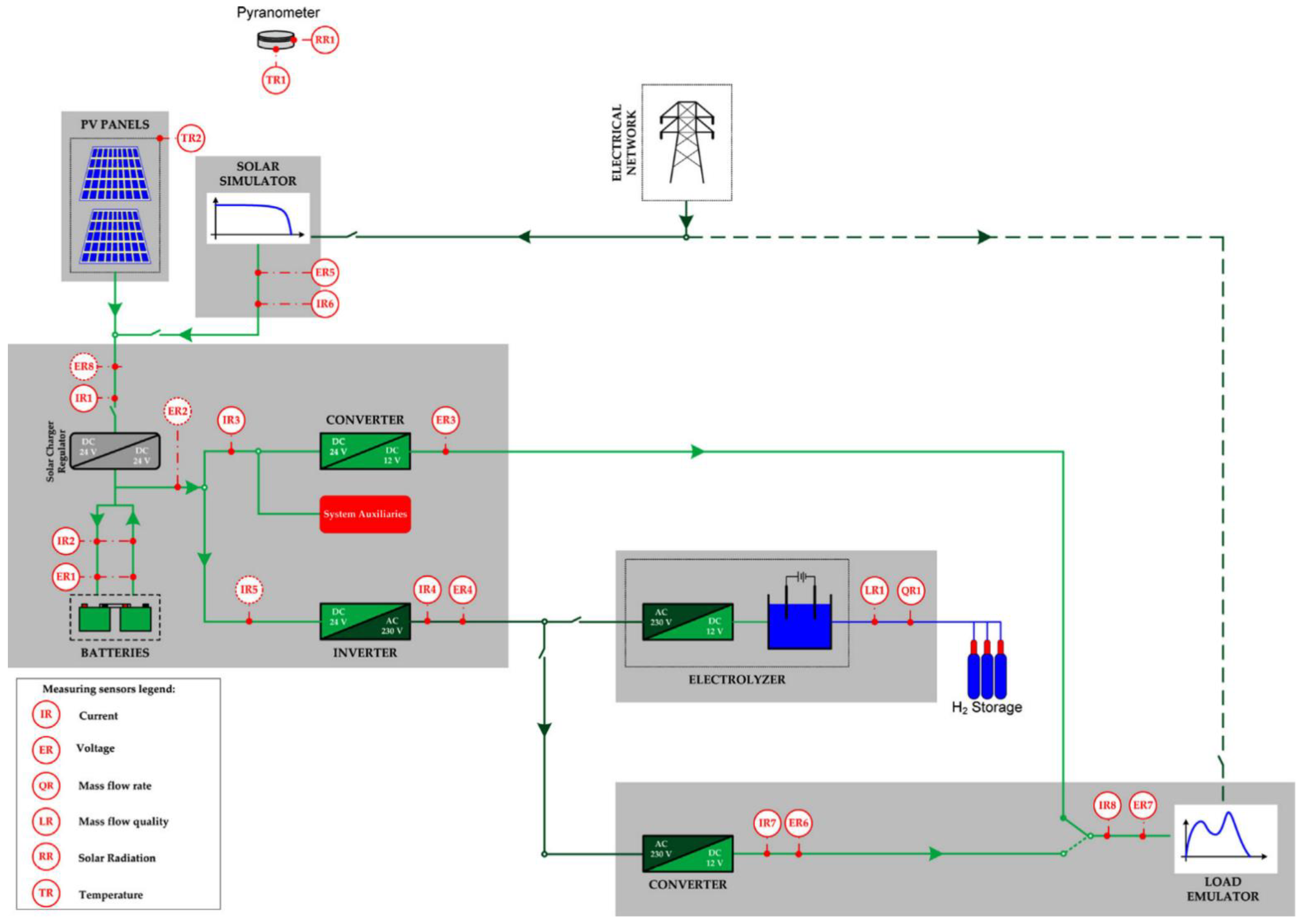
Nanogrids are small-scale microgrid systems, and are primarily applied to university campuses, living labs, and single-family households. Ancona et al. [7] developed a hybrid PV-RHFC nanogrid system for a university campus in Bologna, Italy (see Figure 11). It consisted of two PV panels (connected in parallel), two gel lead-acid batteries (connected in series), and an RHFC subsystem with three hydrogen canisters. It was concluded that the performance of the system is highly dependent on the operating conditions. Petrollese et al. [49] developed a laboratory-scale system at the University of Seville, Spain. The system was simulated in a 24-h interval for both a summer and a winter day to test the reliability and performance of its control unit. The results showed that the nanogrid can reduce the operating costs and maximize the contribution of the HSU. Mendes et al. [13] optimized the economic performance of a laboratory-based, grid-connected, hybrid PV-RHFC nanogrid system, which included battery storage and connection to a BEV charging station. A hierarchical model predictive control methodology was applied to maintain nanogrid stability and manage power import/export to the central grid. The aim was to maximize self-consumption, control the energy storage units, and allow charging of the parked BEVs. Okundamiya [54] investigated the potential of installing a hybrid PV-RHFC microgrid system in a university building at Ambrose Alli University, Nigeria to improve the reliability of the conventional electricity supply from the central power grid (see Figure 12). Rossi et al. [55] developed a hybrid PV-RHFC nanogrid system for residential application. The results showed that future hybrid nanogrids with 700 bar hydrogen storage could be ideal for off-grid operation since they can minimize environmental impact. In Table 3, the aforementioned applications for nanogrid systems are summarized.

4.2. Multipurpose Microgrid Systems

In conventional, centralized power plants, frequent issues related to power network congestions and rapid fluctuations of dynamic load profiles force the curtailment of RES-generated power. FCEVs are fueled with hydrogen to generate electricity to power their electric motors. Since FCEVs do not operate constantly, the stored hydrogen in their HSUs could be used to power local microgrids when the cars are parked, in a so-called vehicle-to-grid scheme [26]. Robledo et al. [30] proposed a microgrid application in the “Green Village”, the Netherlands, consisting of building-integrated PV (BIPV) solar panels, and also fueling of FCEVs, for combined mobility and power generation, targeting net-zero-energy operation. The main objective was to assess vehicle-to-grid operation with the FCEVs also acting as power generators. The maximum DC power output of the car was 10 kW, which was converted to AC power for central power grid export with an off-board DC/AC inverter. The system performed at a tank-to-grid efficiency of 44% at maximum power output. The researchers performed annual simulations with ten households and five cars; the results indicated that the proposed system could help reduce central grid-imported electricity by 71%. Carroquino et al. [41] developed a microgrid system with three PV arrays to provide power to a wastewater treatment plant of a winery and the pumping station of the irrigation system of a vineyard. The system also included a small battery for short-term storage and an RHFC subsystem to generate hydrogen, which was provided to a refueling station to fuel PEMFC-based FCEVs. The system resulted in fuel savings, which would otherwise have to be provided to run a conventional diesel engine-based vehicle. He et al. [21] modeled a multi-purpose, grid-connected, microgrid system for application in California, USA for generation of electrical energy, heating and hydrogen and integration to low-rise households with rooftop PV panels, FCEVs, a hydrogen station, and hydrogen pipelines. The results showed that the proposed microgrid system can improve performance during idling and reduce annual net hydrogen consumption from 127 to 1.2 kg per vehicle. The research team also concluded that operating at the minimum input power for the electrolyzer and fuel cell units (65 and 80 kW, respectively) can decrease the maximum mean hourly grid power by 24% and the annual energy cost by 39%.
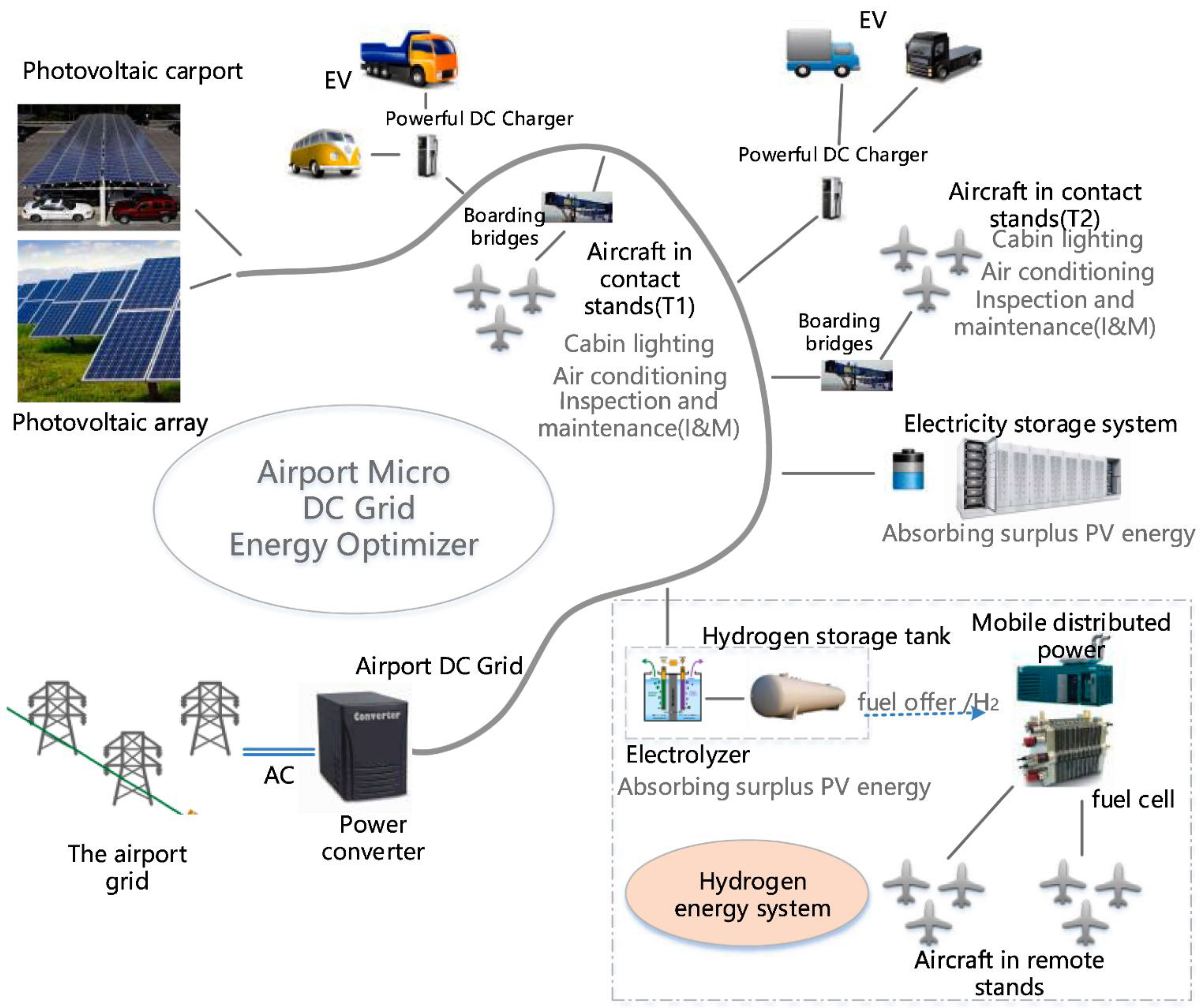
Dispenza et al. [11] developed a hybrid PV-RHFC microgrid system with a fueling station for smart city application, with 100 kW rooftop PV panels, and 300 kWh battery units (16 sodium nickel chloride high-temperature batteries). The system aimed at the provision of both electricity and hydrogen to BEVs and FCEVs, respectively. Later, the same research group [31] conducted an economic evaluation of the aforementioned microgrid system, by considering three case studies (hydrogen generated only with electricity from the central power grid, hydrogen generated with electricity from a grid-connected PV subsystem, and hydrogen generated from a grid-connected subsystem with battery storage). The results showed that the integration of the PV subsystem can provide 50% savings in terms of electricity purchase cost, while the battery storage can provide an additional 11% in savings. In addition, carbon emissions can be reduced by 45.26 tCO2/year and 49.15 tCO2/year in the second and third case studies, respectively. Xiang et al. [14] developed a hybrid PV-RHFC microgrid system with battery storage for APU application for aircrafts and electric vehicles, aiming at an electrified airport energy system (see Figure 13). A mixed-integer linear programming optimization method was utilized to optimize the capacities of the integrated components aiming at reaching the minimum cost and reducing carbon emissions. The results showed that the proposed system can help reduce the total annual cost and carbon emissions by 42% and 67%, respectively. Jaramillo and Weidlich [45] applied a multi-objective mixed-integer linear programming model in a grid-connected, hybrid PV-RHFC microgrid system to optimize the operation scheduling of the components. The aim of the system model was to control the microgrid in a field trial set up for application in Southwest Germany. The results showed that the energy storage subsystem can be mainly used to trim power peaks from the central grid, while keeping the peak at a minimum power. In Table 4, the aforementioned applications for multipurpose microgrid systems are summarized.

4.3. Integration with Other Power Generating and Energy Storage Technologies

Larger microgrid systems may include multiple types of power generating and energy storage technologies to be able to generate different types of useful energy, i.e., electricity, heating, cooling, hydrogen, drinking water, etc. [56]. Microgrids may be coupled to wind turbines, in addition to PV panels, in order to increase their power output capacity [26]. Chen et al. [46] considered four different hydrogen microgrid configurations with PVs and wind turbines for a hydrogen refueling station for application in Shanghai, China. These four configurations were specifically the following: (a) onsite hydrogen supply with standalone PV-wind turbine-based power generation, (b) onsite hydrogen supply with grid-connected PV-wind turbine power generation, (c) off-site hydrogen supply with standalone PV-wind turbine-based power generation, and (d) off-site hydrogen supply with grid-connected PV-wind turbine power generation. The results of the study suggested that the last configuration was the best in terms of cost, accounting for both the total net present cost and the levelized cost of energy. Mukherjee et al. [25] developed a microgrid system model combining PVs, wind turbines, an RHFC subsystem, and FCEVs, to supply backup power to a community in Cornwall, Ontario, Canada. The study included a failure mode and effect analysis to investigate the safety aspect of the proposed microgrid system. The system was optimized to supply a peak power output of 5.41 MW (including a 0.4 MW PV subsystem, a 1.6 MW wind turbine subsystem, and a 3 MW backup fuel cell subsystem for a two-day blackout period), while 38 Toyota Mirai FCEVs were included in a vehicle-to-grid operational mode. However, the results showed that the proposed system was not economically sustainable in terms of the net present value at the end of its life.
Conventional heat and power generating technologies have also been considered for integration into microgrid systems. Colombo et al. [57] developed a microgrid system model for application at the University of California-Irvine, USA, which would include an already existing natural gas-fueled, combined-cycle power plant, an electric chiller, and thermal energy storage units. The microgrid would add a total of 37 MW PV panels (15 MW of fixed installations and up to 22 MW of ground-mounted 2-axis tracking systems), and a minimum aggregated power capacity of 300 kW SOECs. The latter was added to absorb at least 80% of the excess annual renewable power production for each renewable capacity scenario, implementing a dispatch strategy able to respond to excess solar power available in the microgrid. The possibility of developing a microgrid system with application on electricity water nexus (wastewater treatment) was presented by Niknejad et al. [44]. The proposed system included a standalone AC/DC (to satisfy DC and AC loads), hybrid PV-RHFC microgrid system, where purified water and hydrogen could be generated via microbial electrolysis cell technology; the generated hydrogen could be used to fuel a PEMFC subsystem.
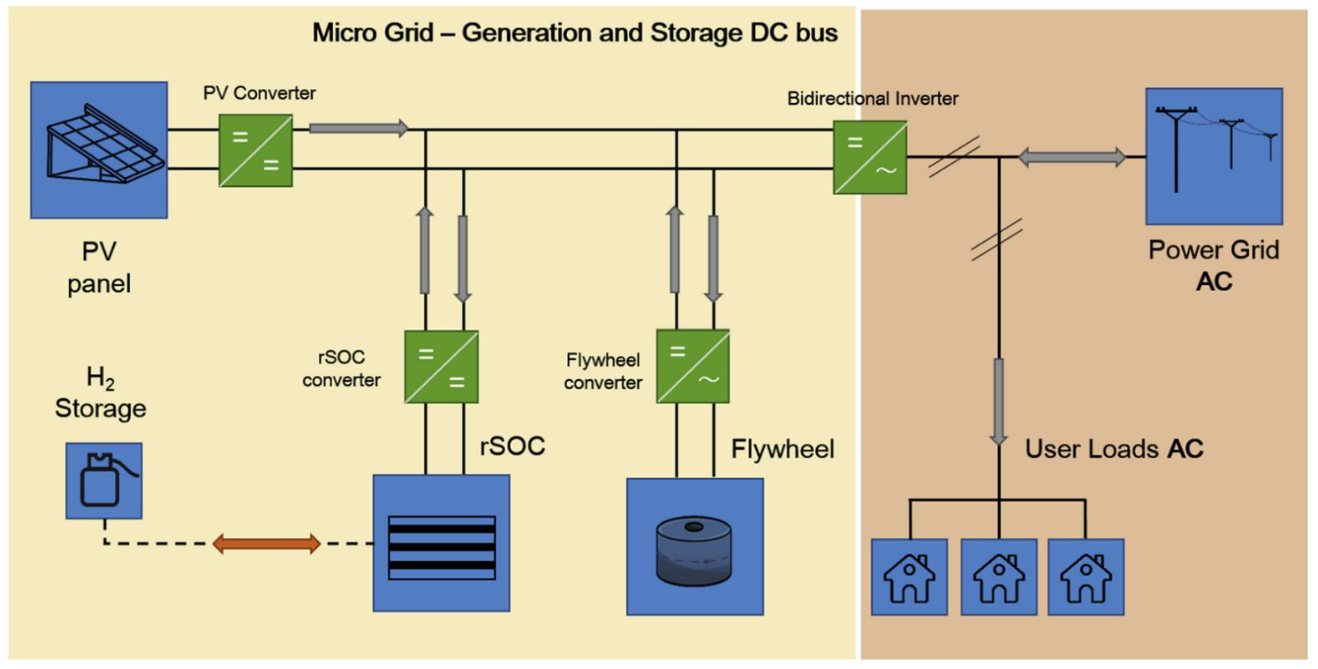
Murthy et al. [56] considered a standalone, hybrid PV-RHFC microgrid system, with metal hydride hydrogen storage. The proposed system aimed at the fulfilment of electrical, thermal and hydrogen loads. The research team conducted a case study for possible application of the system in a typical Indian village, where 50 households would be supplied with 100 kWh/day. The same group investigated the integration of battery storage to the microgrid [47]. The results showed that a significant advantage of the proposed system is the fact that the metal hydride HSU processes create the possibility for heat recovery from the heat release during adsorption, in addition to the generated heat from the fuel cell. Baldinelli et al. [20] investigated a reversible solid oxide cell subsystem (i.e., operating in both electrolyzer and fuel cell modes), where a flywheel was coupled to the microgrid to solve the resulting load-following issues (see Figure 14). The proposed system, aiming at the improvement of the fast-ramping and peak-shaving capabilities, achieved an increase in RES self-consumption efficiency by 11.5%, in comparison to a system without storage. Castellanos et al. [22] developed and optimized an autonomous microgrid system model to cover the power loads of a rural village in West Bengal, India (22 MWh/year). The researchers considered seven scenarios, with various power generators (anaerobic digestion with biogas, combined-heat-and-power, and PVs) and storage technologies (vanadium redox batteries, and hydrogen energy), and the components were sized for each scenario. In Table 5, the aforementioned applications for integration with other power generating and energy storage technologies are summarized.

5. Critical Analysis and Discussion of Hybrid PV-RHFC Microgrid Systems

The advantages and disadvantages of hybrid PV-RHFC microgrid systems can be identified in relation to the key factors and characteristics that affect their operation and performance. In these systems, operational scheduling of the components is critical because it allows minimization of running costs, and optimization of total efficiency [29]. For example, if 100 kW is produced from solar PVs, and the electrolyzer and fuel cell efficiencies are around 60% and 40%, respectively (with negligible hydrogen storage and DC-DC power converter losses), around 24 kW DC electricity would be available at the exit of the fuel cell. It is also important to reduce the capacity of the main integrated components (i.e., PVs, battery, fuel cell and electrolyzer stacks, and HSU) to minimize the total capital cost, which is very important in a hybrid PV-RHFC microgrid system [26]. Apart from the typical grid-to-vehicle mode of operation, it is also desirable to operate in reverse, i.e., vehicle-to-grid, in order to maximize the self-consumption [25]. The stored hydrogen in the HSUs of the FCEVs can be used to power local microgrids when the cars are parked (in this case the FCEV acts as a power generator) [30]. In addition, hydrogen generated from RES can be stored in hydrogen refilling stations (in large amounts for long-term storage) [21]. A hybrid PV-RHFC microgrid system can be designed to serve multiple types of buildings (i.e., residential, public, commercial, and industrial) and multiple purposes (i.e., charge BEVs or fuel FCEVs) [26]. The long-term energy storage provided by a hybrid PV-RHFC microgrid system can help achieve a net-zero-energy operational scheme, which is not easily achievable through short-term battery storage [30]. Larger microgrid systems may include multiple types of power generating and energy storage technologies to be able to generate different types of useful energy (i.e., electricity, heating, cooling, hydrogen, drinking water, etc.) [56]. The resulting nonlinear microgrid systems, along with their multiple modes of operation require the application of advanced EMS control strategies. It is necessary to provide optimal control capabilities to the microgrid to ensure smooth operation of the fuel cell and electrolyzer stacks and balance between supply vs. demand. Various control strategies have been considered for microgrid integration, such as model predictive control, hysteresis band control strategy, equivalent consumption and minimization strategy, and state machine [39].
Hybrid PV-RHFC microgrid systems have some important advantages. The RHFC subsystem offers long-term storage (in addition to instant short-term storage offered by the battery) [29]. In addition, the added power availability and self-consumption allows less congestion of central power grids, since power generation in centralized power stations can be reduced [25]. Long-term storage allows for an increase in RES-generated power and hydrogen storage offers negligible self-discharge rates [17]. It is also important to consider the high energy density of hydrogen, which is particularly important in transport applications, and in general in applications where space and weight restrictions are unavoidable [26]. Hybrid PV-RHFC microgrid systems also have the ability of combining multiple applications, i.e., servicing various types of buildings, providing electricity to BEVs (BEV station), hydrogen to FCEVs (hydrogen station), and operating at both grid-to-vehicle and vehicle-to-grid modes. These capabilities can in turn reduce the curtailment of RES-generated power from rapid fluctuations of dynamic load profiles [48]. However, some important disadvantages can be identified in hybrid PV-RHFC microgrid systems. The complexity created by the additional components of the RHFC subsystem and the nonlinear operation of multiple types of energy storage technologies require effective dimensioning of the capacities of the units with the application of advanced optimization methods [11]. Therefore, it is necessary to apply process integration techniques to optimally couple all components to improve power-sharing and minimize the capacity of the integrated components (and moreover the total capital cost of the overall system). Currently, the cost of fuel cell and electrolyzer stacks is very high which reduces the commercialization potential of hybrid PV-RHFC microgrid systems [25]. These systems are not economically sustainable in terms of the net present value at the end of their lifetime [23]. It is also necessary to include dynamic models to realistically simulate operation, which require sophisticated modeling and optimization methods. The operation of the HSU can be complicated as well because depending on the type of hydrogen storage, a hydrogen compressor is needed for compressed hydrogen, while a cooling/heating system is needed for metal hydride technology [47]. In addition, it is necessary to purify tap water before use in the electrolyzer because electrolyzers require distilled water with very low conductivity (typically below 2 μS/cm) to avoid early degradation of the electrolyzer [41]. The main advantages and disadvantages of hybrid PV-RHFC microgrid systems are summarized in Table 6.

6. Future Prospects, Challenges, and Key Directions for Future Research

The current status of hybrid PV-RHFC microgrid systems can help identify their future prospects. An important challenge that must be overcome to reach the commercialization stage of hybrid PV-RHFC microgrid systems is the reduction of the currently high capital cost. Although the capital cost of solar PV modules has decreased significantly in recent years, the capital cost of RHFC technology is still rather high. This is caused by the high cost of fuel cell and electrolyzer stacks since platinum-based catalysts and ion exchange membranes are not yet cost-effective. New cheaper materials, along with more effective manufacturing methods, are needed to reduce stack initial costs. Another issue is the absence of commercially-available hybrid PV-RHFC microgrid system solutions. In addition, the nonlinearity nature of these systems due to their complexity in terms of component connection and frequent operational mismatch causes low reliability in terms of energy flow sharing and control.
The key direction for future research that can help resolve the aforementioned challenges is the application of more effective optimization methods on complete hybrid PV-RHFC microgrid systems from the design stage, simultaneously with effective control strategies. These procedures will help reduce component/subsystem capacities and initial costs. Moreover, they can increase total efficiency and system reliability. Of equal importance is the need to design and manufacture complete, turnkey solutions, since the currently available systems are being developed from components or subsystems that were not designed and manufactured for the purpose of building hybrid PV-RHFC microgrid systems. In addition to advanced modeling and optimization methods, effective EMS units must be integrated to monitor, control, and optimize the total system in order to avoid operational issues and ensure flexibility and reliability of the energy flows that are related to supply, storage, and demand. These will help to increase the commercialization potential of hybrid PV-RHFC microgrid systems, to become a competitive solution in the future energy market, which is expected to favor the creation of smaller-scale, decentralized energy systems with high efficiency, self-sufficiency, energy flow reliability, and higher RES penetration.

7. Conclusions

This paper provides information on the recent research progress in hybrid PV-RHFC microgrid systems. The characteristics of the different components (PV modules, electrolyzer, and fuel cell stacks, energy storage units, power electronics, and controllers) that need to be integrated into the hybrid PV-RHFC microgrid systems are analyzed in terms of technology type for all possible options. Subsequently, the main modeling and optimization methods and control strategies for hybrid PV-RHFC microgrid systems were discussed. Additionally, the various possible applications of hybrid PV-RHFC microgrid systems are analyzed based on the recent publication activity in the open literature. These applications differentiate in terms of scale (e.g., nanogrid vs. microgrid), purpose (e.g., stationary, transport, combined applications), and further integration with other power generating and energy storage technologies. Finally, critical analysis and discussion of hybrid PV-RHFC microgrid systems were conducted based on their current status in technoeconomic terms. Their advantages and disadvantages were identified, and emphasis was given to the existing issues and shortcomings that need to be resolved in order to increase their future commercialization prospects.
Overall, although the lifetime of fuel cell and electrolyzer stacks has increased in recent years, the main economic factor that limits the commercialization of hybrid PV-RHFC microgrid systems is the current high capital cost of the RHFC subsystem since the initial cost of solar PV panels has dropped significantly. The reason for this is the current high cost of fuel cell and electrolyzer stacks, caused by the high cost of platinum-based catalysts and ion exchange membranes. Additionally, to increase the commercialization potential of hybrid PV-RHFC microgrid systems in the future, their total capital cost must drop further in the future to ultimately reduce their lifecycle cost and become more competitive than currently. To achieve this, it will require the design and manufacturing of complete turnkey hybrid PV-RHFC microgrid systems. At the design stage, in addition to advanced modeling and optimization methods, effective EMS units must be integrated to monitor, control, and optimize the total system in order to avoid operational issues and ensure flexibility and reliability of the energy flows that are related to supply, storage, and demand.

Author Contributions

Conceptualization, A.A.; methodology, A.A.; formal analysis, A.A.; investigation, A.A.; resources, G.E.G.; data curation, A.A.; writing—original draft preparation, A.A.; writing—review and editing, A.A., G.E.G. and P.P.; visualization, A.A. and G.E.G.; supervision, G.E.G. and P.P.; project administration, G.E.G. All authors have read and agreed to the published version of the manuscript.

Funding

This research received no external funding.

Data Availability Statement

Not applicable.

Acknowledgments

In this article, copyright permission has been obtained for Figure 1, Figure 2, Figure 3, Figure 4, Figure 5, Figure 6, Figure 7, Figure 8, Figure 9, Figure 10, Figure 11, Figure 12, Figure 13 and Figure 14 from their original publisher (Elsevier). The documents for the permission are available upon request.

Conflicts of Interest

The authors declare no conflict of interest.

Abbreviations

ACAlternating Current
AECAlkaline Electrolyzer Cell
APUAuxiliary Power Unit
BEVBattery Electric Vehicle
BIPVBuilding Integrated Photovoltaic
DCDirect Current
EMSEnergy Management System
FCEVFuel Cell Electric Vehicle
HSUHydrogen Storage Unit
PEMECProton Exchange Membrane Electrolyzer Cell
PEMFCProton Exchange Membrane Fuel Cell
PVPhotovoltaic
RESRenewable Energy Sources
RHFCRegenerative Hydrogen Fuel Cell
RTURemote Terminal Unit
SCADASupervisory Control and Data Acquisition
SOECSolid Oxide Electrolyzer Cell
SOFCSolid Oxide Fuel Cell

References

  1. Schlachtberger, D.P.; Brown, T.; Schäfer, M.; Schramm, S.; Greiner, M. Cost optimal scenarios of a future highly renewable European electricity system: Exploring the influence of weather data, cost parameters and policy constraints. Energy 2018, 163, 100–114. [Google Scholar] [CrossRef] [Green Version]
  2. Benavente, F.; Lundblad, A.; Campana, P.E.; Zhang, Y.; Cabrera, S.; Lindbergh, G. Photovoltaic/battery system sizing for rural electrification in Bolivia: Considering the suppressed demand effect. Appl. Energy 2019, 235, 519–528. [Google Scholar] [CrossRef]
  3. Sun, C.; Zhang, H. Review of the Development of First-Generation Redox Flow Batteries: Iron-Chromium System. ChemSusChem 2022, 15, e202101798. [Google Scholar] [CrossRef]
  4. Arsalis, A.; Alexandrou, A.N.; Georghiou, G.E. Thermoeconomic modeling and parametric study of a photovoltaic-assisted 1 MWe combined cooling, heating, and power system. Energies 2016, 9, 663. [Google Scholar] [CrossRef] [Green Version]
  5. Arsalis, A.; Georghiou, G.E. A decentralized, hybrid photovoltaic-solid oxide fuel cell system for application to a commercial building. Energies 2018, 11, 3512. [Google Scholar] [CrossRef] [Green Version]
  6. Arsalis, A.; Georghiou, G.E. Thermoeconomic optimization of a hybrid photovoltaic-solid oxide fuel cell system for decentralized application. Appl. Sci. 2019, 9, 5450. [Google Scholar] [CrossRef] [Green Version]
  7. Ancona, M.A.; Bianchi, M.; Branchini, L.; De Pascale, A.; Melino, F.; Peretto, A.; Rosati, J.; Scarponi, L.B. From solar to hydrogen: Preliminary experimental investigation on a small scale facility. Int. J. Hydrogen Energy 2017, 42, 20979–20993. [Google Scholar] [CrossRef]
  8. Wu, Y.; Wu, Y.; Guerrero, J.M.; Vasquez, J.C. A comprehensive overview of framework for developing sustainable energy internet: From things-based energy network to services-based management system. Renew. Sustain. Energy Rev. 2021, 150, 111409. [Google Scholar] [CrossRef]
  9. Obara, S.; Morel Rios, J.R.; Okada, M. Control of cyclic fluctuations in solid oxide fuel cell cogeneration accompanied by photovoltaics. Energy 2015, 91, 994–1008. [Google Scholar] [CrossRef]
  10. Marocco, P.; Ferrero, D.; Lanzini, A.; Santarelli, M. The role of hydrogen in the optimal design of off-grid hybrid renewable energy systems. J. Energy Storage 2022, 46, 103893. [Google Scholar] [CrossRef]
  11. Dispenza, G.; Sergi, F.; Napoli, G.; Randazzo, N.; Di Novo, S.; Micari, S.; Antonucci, V.; Andaloro, L. Development of a solar powered hydrogen fueling station in smart cities applications. Int. J. Hydrogen Energy 2017, 42, 27884–27893. [Google Scholar] [CrossRef]
  12. Vazquez, S.; Lukic, S.M.; Galvan, E.; Franquelo, L.G.; Carrasco, J.M. Energy storage systems for transport and grid applications. IEEE Trans. Ind. Electron. 2010, 57, 3881–3895. [Google Scholar] [CrossRef] [Green Version]
  13. Mendes, P.R.C.; Isorna, L.V.; Bordons, C.; Normey-Rico, J.E. Energy management of an experimental microgrid coupled to a V2G system. J. Power Sources 2016, 327, 702–713. [Google Scholar] [CrossRef]
  14. Xiang, Y.; Cai, H.; Liu, J.; Zhang, X. Techno-economic design of energy systems for airport electrification: A hydrogen-solar-storage integrated microgrid solution. Appl. Energy 2021, 283, 116374. [Google Scholar] [CrossRef]
  15. Karstedt, J.; Ogrzewalla, J.; Severin, C.; Pischinger, S. Development and design of experiments optimization of a high temperature proton exchange membrane fuel cell auxiliary power unit with onboard fuel processor. J. Power Sources 2011, 196, 9998–10009. [Google Scholar] [CrossRef]
  16. Kupecki, J.; Jewulski, J.; Motylinski, K. Parametric evaluation of a micro-CHP unit with solid oxide fuel cells integrated with oxygen transport membranes. Int. J. Hydrogen Energy 2015, 40, 11633–11640. [Google Scholar] [CrossRef] [Green Version]
  17. Mah, A.X.Y.; Ho, W.S.; Hassim, M.H.; Hashim, H.; Ling, G.H.T.; Ho, C.S.; Muis, Z.A. Optimization of a standalone photovoltaic-based microgrid with electrical and hydrogen loads. Energy 2021, 235, 121218. [Google Scholar] [CrossRef]
  18. Puranen, P.; Kosonen, A.; Ahola, J. Techno-economic viability of energy storage concepts combined with a residential solar photovoltaic system: A case study from Finland. Appl. Energy 2021, 298, 117199. [Google Scholar] [CrossRef]
  19. Zakeri, B.; Cross, S.; Dodds, P.E.; Gissey, G.C. Policy options for enhancing economic profitability of residential solar photovoltaic with battery energy storage. Appl. Energy 2021, 290, 116697. [Google Scholar] [CrossRef]
  20. Baldinelli, A.; Barelli, L.; Bidini, G. Progress in renewable power exploitation: Reversible solid oxide cells-flywheel hybrid storage systems to enhance flexibility in micro-grids management. J. Energy Storage 2019, 23, 202–219. [Google Scholar] [CrossRef]
  21. He, Y.; Zhou, Y.; Yuan, J.; Liu, Z.; Wang, Z.; Zhang, G. Transformation towards a carbon-neutral residential community with hydrogen economy and advanced energy management strategies. Energy Convers. Manag. 2021, 249, 114834. [Google Scholar] [CrossRef]
  22. Castellanos, J.G.; Walker, M.; Poggio, D.; Pourkashanian, M.; Nimmo, W. Modelling an off-grid integrated renewable energy system for rural electrification in India using photovoltaics and anaerobic digestion. Renew. Energy 2015, 74, 390–398. [Google Scholar] [CrossRef] [Green Version]
  23. Bracco, S.; Delfino, F.; Pampararo, F.; Robba, M.; Rossi, M. The University of Genoa smart polygeneration microgrid test-bed facility: The overall system, the technologies and the research challenges. Renew. Sustain. Energy Rev. 2013, 18, 442–459. [Google Scholar] [CrossRef]
  24. Arsalis, A. A comprehensive review of fuel cell-based micro-combined-heat-and-power systems. Renew. Sustain. Energy Rev. 2019, 105, 391–414. [Google Scholar] [CrossRef]
  25. Mukherjee, U.; Maroufmashat, A.; Ranisau, J.; Barbouti, M.; Trainor, A.; Juthani, N.; El-Shayeb, H.; Fowler, M. Techno-economic, environmental, and safety assessment of hydrogen powered community microgrids; case study in Canada. Int. J. Hydrogen Energy 2017, 42, 14333–14349. [Google Scholar] [CrossRef]
  26. Alavi, F.; Park Lee, E.; van de Wouw, N.; De Schutter, B.; Lukszo, Z. Fuel cell cars in a microgrid for synergies between hydrogen and electricity networks. Appl. Energy 2017, 192, 296–304. [Google Scholar] [CrossRef] [Green Version]
  27. Alam, M.; Kumar, K.; Verma, S.; Dutta, V. Renewable sources based DC microgrid using hydrogen energy storage: Modelling and experimental analysis. Sustain. Energy Technol. Assess. 2020, 42, 100840. [Google Scholar] [CrossRef]
  28. Li, Q.; Li, R.; Pu, Y.; Li, S.; Sun, C.; Chen, W. Coordinated control of electric-hydrogen hybrid energy storage for multi-microgrid with fuel cell/electrolyzer/PV/battery. J. Energy Storage 2021, 42, 103110. [Google Scholar] [CrossRef]
  29. Abulanwar, S.; Ghanem, A.; Rizk, M.E.M.; Hu, W. Adaptive synergistic control strategy for a hybrid AC/DC microgrid during normal operation and contingencies. Appl. Energy 2021, 304, 117756. [Google Scholar] [CrossRef]
  30. Robledo, C.B.; Oldenbroek, V.; Abbruzzese, F.; van Wijk, A.J.M. Integrating a hydrogen fuel cell electric vehicle with vehicle-to-grid technology, photovoltaic power and a residential building. Appl. Energy 2018, 215, 615–629. [Google Scholar] [CrossRef]
  31. Dispenza, G.; Sergi, F.; Napoli, G.; Antonucci, V.; Andaloro, L. Evaluation of hydrogen production cost in different real case studies. J. Energy Storage 2019, 24, 100757. [Google Scholar] [CrossRef]
  32. Smets, A.; Jager, K.; Isabella, O.; van Swaaij, R.; Zeman, M. Solar Energy: The Physics and Engineering of Photovoltaic Conversion, Technologies and Systems; UIT Cambridge: Cambridge, UK, 2016; ISBN 9780128095973. [Google Scholar]
  33. Larminie, J.; Dicks, A.L. Fuel Cell Systems Explained, 2nd ed.; Wiley: Chichester, UK, 2003. [Google Scholar]
  34. Barbir, F. PEM Fuel Cells: Theory and Practice, 2nd ed.; Elsevier Academic Press: Burlington, MA, USA, 2013; ISBN 9780123877109. [Google Scholar]
  35. Arsalis, A.; Alexandrou, A.N.; Georghiou, G.E. Thermoeconomic modeling of a completely autonomous, zero-emission photovoltaic system with hydrogen storage for residential applications. Renew. Energy 2018, 126, 354–369. [Google Scholar] [CrossRef]
  36. de Rubeis, T.; Nardi, I.; Paoletti, D.; Di Leonardo, A.; Ambrosini, D.; Poli, R.; Sfarra, S. Multi-year consumption analysis and innovative energy perspectives: The case study of Leonardo da Vinci International Airport of Rome. Energy Convers. Manag. 2016, 128, 261–272. [Google Scholar] [CrossRef]
  37. Zeng, Y.; Yang, Z.; Lu, F.; Xie, Y. A novel tin-bromine redox flow battery for large-scale energy storage. Appl. Energy 2019, 255, 113756. [Google Scholar] [CrossRef]
  38. Zhang, H.; Sun, C. Cost-effective iron-based aqueous redox flow batteries for large-scale energy storage application: A review. J. Power Sources 2021, 493, 229445. [Google Scholar] [CrossRef]
  39. Kumar, K.; Alam, M.; Dutta, V. Energy management strategy for integration of fuel cell-electrolyzer technologies in microgrid. Int. J. Hydrogen Energy 2021, 46, 33738–33755. [Google Scholar] [CrossRef]
  40. Kumar, K.; Alam, M.; Verma, S.; Dutta, V. Analysis of metal hydride storage on the basis of thermophysical properties and its application in microgrid. Energy Convers. Manag. 2020, 222, 113217. [Google Scholar] [CrossRef]
  41. Carroquino, J.; Roda, V.; Mustata, R.; Yago, J.; Valiño, L.; Lozano, A.; Barreras, F. Combined production of electricity and hydrogen from solar energy and its use in the wine sector. Renew. Energy 2018, 122, 251–263. [Google Scholar] [CrossRef] [Green Version]
  42. Nadal, A.; Ruby, A.; Bourasseau, C.; Riu, D.; Berenguer, C. Accounting for techno-economic parameters uncertainties for robust design of remote microgrid. Int. J. Electr. Power Energy Syst. 2020, 116, 105531. [Google Scholar] [CrossRef] [Green Version]
  43. Labrador Rivas, A.E.; Abrão, T. Faults in smart grid systems: Monitoring, detection and classification. Electr. Power Syst. Res. 2020, 189, 106602. [Google Scholar] [CrossRef]
  44. Niknejad, P.; Venneti, S.; Vasefi, M.; Jeffryes, C.; Barzegaran, M.R. An electrochemically assisted AC/DC microgrid configuration with waste water treatment capability. Electr. Power Syst. Res. 2018, 162, 207–219. [Google Scholar] [CrossRef]
  45. Bolívar Jaramillo, L.; Weidlich, A. Optimal microgrid scheduling with peak load reduction involving an electrolyzer and flexible loads. Appl. Energy 2016, 169, 857–865. [Google Scholar] [CrossRef]
  46. Chen, Q.; Gu, Y.; Tang, Z.; Wang, D.; Wu, Q. Optimal design and techno-economic assessment of low-carbon hydrogen supply pathways for a refueling station located in Shanghai. Energy 2021, 237, 121584. [Google Scholar] [CrossRef]
  47. Srinivasa Murthy, S.; Dutta, P.; Sharma, R.; Rao, B.S. Parametric studies on a stand-alone polygeneration microgrid with battery storage. Therm. Sci. Eng. Prog. 2020, 19, 100608. [Google Scholar] [CrossRef]
  48. Xie, Y.; Ueda, Y.; Sugiyama, M. Greedy energy management strategy and sizing method for a stand-alone microgrid with hydrogen storage. J. Energy Storage 2021, 44, 103406. [Google Scholar] [CrossRef]
  49. Petrollese, M.; Valverde, L.; Cocco, D.; Cau, G.; Guerra, J. Real-time integration of optimal generation scheduling with MPC for the energy management of a renewable hydrogen-based microgrid. Appl. Energy 2016, 166, 96–106. [Google Scholar] [CrossRef]
  50. de Oliveira-Assis, L.; García-Triviño, P.; Soares-Ramos, E.P.P.; Sarrias-Mena, R.; García-Vázquez, C.A.; Ugalde-Loo, C.E.; Fernández-Ramírez, L.M. Optimal energy management system using biogeography based optimization for grid-connected MVDC microgrid with photovoltaic, hydrogen system, electric vehicles and Z-source converters. Energy Convers. Manag. 2021, 248, 114808. [Google Scholar] [CrossRef]
  51. García, P.; Torreglosa, J.P.; Fernández, L.M.; Jurado, F.; Langella, R.; Testa, A. Energy management system based on techno-economic optimization for microgrids. Electr. Power Syst. Res. 2016, 131, 49–59. [Google Scholar] [CrossRef]
  52. Konstantinopoulos, S.A.; Anastasiadis, A.G.; Vokas, G.A.; Kondylis, G.P.; Polyzakis, A. Optimal management of hydrogen storage in stochastic smart microgrid operation. Int. J. Hydrogen Energy 2018, 43, 490–499. [Google Scholar] [CrossRef]
  53. Li, Z.; Dong, H.; Hou, S.; Cheng, L.; Sun, H. Coordinated control scheme of a hybrid renewable power system based on hydrogen energy storage. Energy Reports 2021, 7, 5597–5611. [Google Scholar] [CrossRef]
  54. Okundamiya, M.S. Integration of photovoltaic and hydrogen fuel cell system for sustainable energy harvesting of a university ICT infrastructure with an irregular electric grid. Energy Convers. Manag. 2021, 250, 114928. [Google Scholar] [CrossRef]
  55. Rossi, F.; Parisi, M.L.; Maranghi, S.; Basosi, R.; Sinicropi, A. Environmental analysis of a nano-grid: A Life Cycle Assessment. Sci. Total Environ. 2020, 700, 134814. [Google Scholar] [CrossRef] [PubMed]
  56. Srinivasa Murthy, S.; Dutta, P.; Sharma, R.; Rao, B.S.; Sharma, R. Performance analysis of a stand-alone polygeneration microgrid. Therm. Sci. Eng. Prog. 2020, 19, 100623. [Google Scholar] [CrossRef]
  57. Colombo, P.; Saeedmanesh, A.; Santarelli, M.; Brouwer, J. Dynamic dispatch of solid oxide electrolysis system for high renewable energy penetration in a microgrid. Energy Convers. Manag. 2020, 204, 112322. [Google Scholar] [CrossRef]
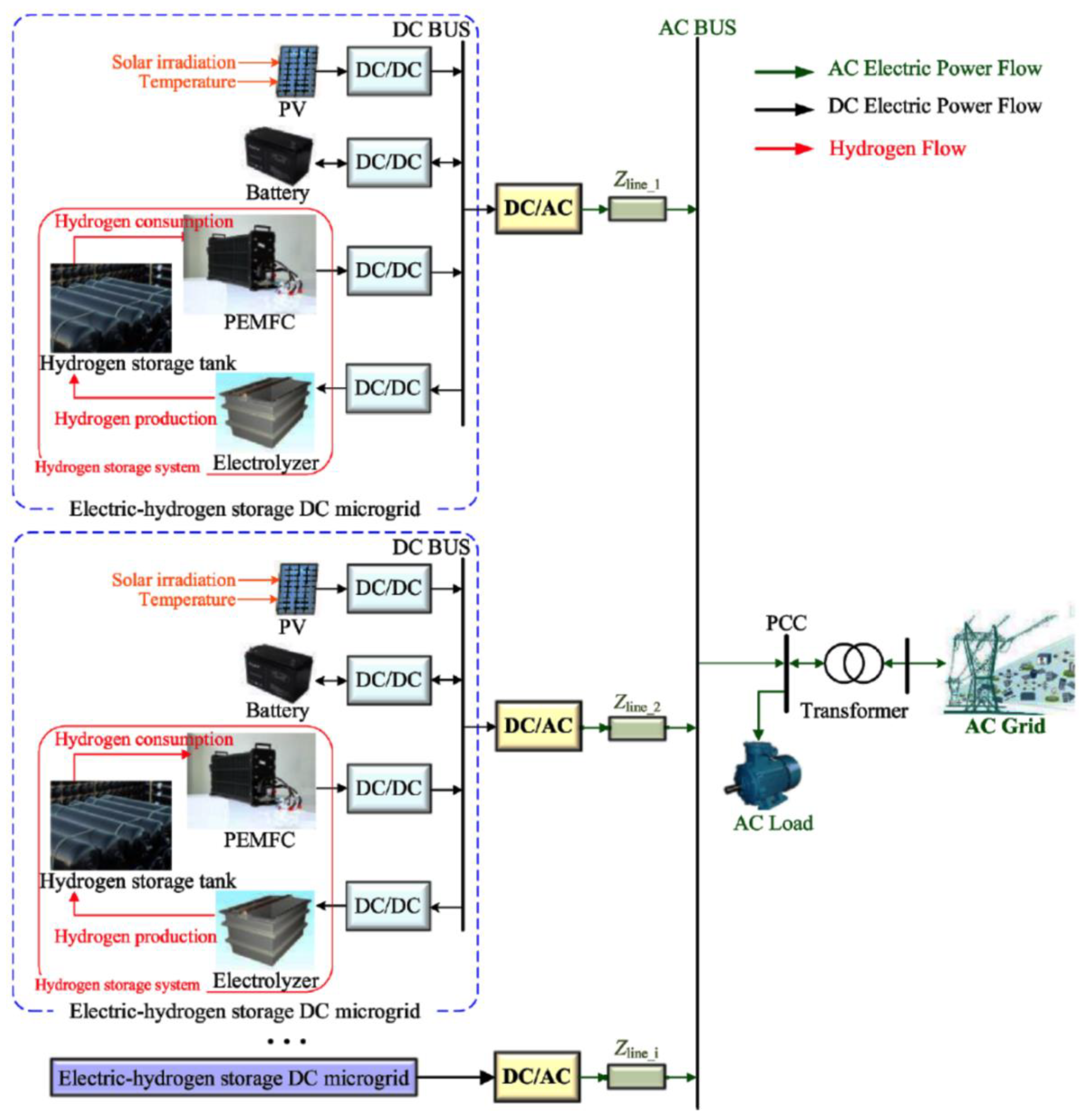
Figure 1. Configuration of a hybrid photovoltaic–regenerative hydrogen fuel cell (PV-RHFC) microgrid system. Reprinted with permission from Ref. [28]. 2021, Elsevier.
Energies 15 03512 g001
Figure 2. Configuration of a standalone hybrid AC/DC microgrid system. Reprinted with permission from Ref. [29]. 2021, Elsevier.
Energies 15 03512 g002
Figure 3. Schematic representation of a “car as power plant” microgrid system. Reprinted with permission from Ref. [26]. 2017, Elsevier.
Energies 15 03512 g003
Figure 4. Schematic representation of an AC/DC PV-RHFC microgrid with wastewater treatment capability. Reprinted with permission from Ref. [44]. 2018, Elsevier.
Energies 15 03512 g004
Figure 5. Schematic representation of a community microgrid with low-rise households, rooftop photovoltaics, fuel cell electric vehicles, and a hydrogen station. Reprinted with permission from Ref. [21]. 2021, Elsevier.
Energies 15 03512 g005
Figure 6. Schematic representation of a microgrid with onsite hydrogen refueling stations. Reprinted with permission from Ref. [46]. 2021, Elsevier.
Energies 15 03512 g006
Figure 7. Schematic representation of a power-to-gas PV-RHFC microgrid system with batteries, and fuel cell electric vehicles. Reprinted with permission from Ref. [41]. 2018, Elsevier.
Energies 15 03512 g007
Figure 8. Schematic representation of a community microgrid system modeled in GAMS. Reprinted with permission from Ref. [25]. 2017, Elsevier.
Energies 15 03512 g008
Figure 9. (a) Block diagram of a model predictive controller. (b) Hierarchical structure of the control system of a microgrid configuration. Reprinted with permission from Ref. [39]. 2021, Elsevier.
Energies 15 03512 g009
Figure 10. Schematic representation of a microgrid that includes an energy management system with a biogeography-based optimization algorithm to control the energy flow between the components. Reprinted with permission from Ref. [50]. 2021, Elsevier.
Energies 15 03512 g010
Figure 11. Flow diagram of a hybrid PV-RHFC laboratory nanogrid. Reprinted with permission from Ref. [7]. 2017, Elsevier.
Energies 15 03512 g011
Figure 12. Flow diagram of a grid-connected PV-RHFC nanogrid for application in a university building. Reprinted with permission from Ref. [54]. 2021, Elsevier.
Energies 15 03512 g012
Figure 13. Schematic configuration of a hybrid PV-RHFC microgrid system with battery storage for auxiliary power application for aircrafts and electric vehicles. Reprinted with permission from Ref. [14]. 2021, Elsevier.
Energies 15 03512 g013
Figure 14. Schematic configuration of a hybrid PV-RHFC microgrid system coupled with a flywheel. Reprinted with permission from Ref. [20]. 2019, Elsevier.
Energies 15 03512 g014
Table 1. Modeling and optimization methods for hybrid PV-RHFC microgrid systems.
MethodPurposeRefs.
Fixed time step for transient operation (MATLAB)Fulfilment of load profile during normal conditions by splitting demand between power generators and energy storage units[29]
Mixed logical dynamical modeling (MATLAB)Minimization of system operating cost[26]
Dynamic control strategy (MATLAB)Optimization of power management during standalone operation[44]
Transient modeling (TRNSYS)Improvement of technoeconomic performance and system flexibility[21]
Optimization of component operational scheduling (MATLAB)Minimization of environmental costs[45]
Particle swarm optimization (MATLAB)Minimization of system annual cost[17]
Component/system sizing (HOMER)Fulfillment of load requirements by considering various power generation options[22]
Modeling, simulation, and sensitivity analysis (HOMER)Minimization of the total net present cost[46]
System optimization (HOMER)Optimization of component capacities[47]
System optimization (iHOGA)Optimization of system design and performance in terms of efficiency and reliability[41]
4-phase modeling (GAMS)Determination of the optimal design, operation, and technoeconomic assessment of the system[25]
Modeling, design optimization and energy management (Odyssey)Minimization of energy cost and maximization of the load fulfillment on an annual basis[42]
Table 2. Control strategies for hybrid PV-RHFC microgrid systems.
Control StrategyPurposeRefs.
Greedy energy management strategyPredictive control for a power-to-hydrogen-to-power system[48]
EMS biogeography-based optimization algorithm Control energy flow between components to optimize hydrogen generation-and-consumption[50]
EMS integrationOptimization of system economic performance by relating component expected lifetime to manufacturing costs[51]
EMS with reserve scheduling Optimal operation of a 17-bus low voltage, grid-tied system to reduce the scheduled energy demand[52]
EMS with quasi-proportional resonance Distribution of power to each power generator[53]
Table 3. Nanogrid system applications.
Nanogrid SystemKey ResultRefs.
University campus System performance highly depends on operating conditions[7]
University labOperating costs can be reduced; HSU contribution can be maximized[49]
Grid-connected labSelf-consumption is maximized[13]
University building Reliability of power supply is improved[54]
ResidentialOff-grid operation is preferred because it can minimize environmental impact[55]
Table 4. Multipurpose microgrid system applications.
Multipurpose SystemKey ResultRefs.
Fueling of FCEVs for combined mobility and power generation (vehicle-to-grid)System can reduce central grid-imported electricity by 71%[30]
Winery wastewater treatment plant; vineyard pumping station for irrigation system Fuel savings (that would have to be provided to operate a conventional diesel engine-based vehicle)[41]
Cogeneration of electricity, heating, and hydrogen System can improve performance during idling and reduce annual net hydrogen consumption from 127 to 1.2 kg per vehicle[21]
Fueling station for smart city applicationProvision of both electricity and hydrogen to BEVs and FCEVs is attainable[11]
Fueling station for smart city application and batteries 50% savings in terms of electricity purchase costs; battery storage can provide an additional 11% of savings[31]
Battery storage for APU application for aircrafts and electric vehiclesReduction of the total annual cost and carbon emissions by 42% and 67%, respectively[14]
Grid-connected, hybrid PV-RHFC microgrid systemThe energy storage subsystem can be used to trim power peaks from the central grid[45]
Table 5. Integration with other power generating and energy storage technologies.
Integrated TechnologiesKey ResultRefs.
Wind turbinesOffsite hydrogen supply with grid-connected PV-wind-turbine power generation is the best in terms of cost (for both total net present cost and levelized cost of energy)[46]
Wind turbines and FCEVsThe proposed system is not economically sustainable in terms of net present value[25]
Natural gas-fueled, combined cycle power plant; electric chiller; thermal energy storage units The dispatch strategy is activated when excess solar power is available in the microgrid[57]
Electricity water nexus (wastewater treatment)Purified water and hydrogen could be generated via microbial electrolysis cell technology; the generated hydrogen could be used to fuel a PEMFC subsystem[44]
BatteriesThe metal hydride HSU processes create the possibility for heat recovery from the heat release during adsorption[47]
FlywheelThe proposed system can increase RES self-consumption efficiency by 11.5%[20]
Anaerobic digestion with biogas; vanadium redox batteriesComponents can be sized for each scenario to find the optimum solution in terms of capital and electricity costs[22]
Table 6. Main advantages and disadvantages of hybrid PV-RHFC microgrid systems.
AdvantagesDisadvantages
Long-term storage capability (due to RHFC)Increased system capital cost (due to the high fuel cell and electrolyzer specific costs)
Increased self-consumptionIncreased system complexity
Negligible self-discharge ratesAdvanced modeling and optimization methods needed due to system nonlinearities
Utilization of the high energy density of hydrogen (particularly important in transport applications)Need for sophisticated EMS control strategies
Multipurpose application capabilities (e.g., electricity, heating, charging BEVs, fueling FCEVs)
Publisher’s Note: MDPI stays neutral with regard to jurisdictional claims in published maps and institutional affiliations.