Article

Fuzzy Algorithms for Diagnosis of Furnace Transformer Insulation Condition

by
Alexander S. Karandaev
1,
Igor M. Yachikov
1,
Andrey A. Radionov
2,*,
Ivan V. Liubimov
3,
Nikolay N. Druzhinin
3 and
Ekaterina A. Khramshina
4
1
Department of Information-Measuring Equipment, South Ural State University, 454080 Chelyabinsk, Russia
2
Department of Automation and Control, Moscow Polytechnic University, 107023 Moscow, Russia
3
Department of Electric Drive and Mechatronics, South Ural State University, 454080 Chelyabinsk, Russia
4
Power Engineering and Automated Systems Institute, Nosov Magnitogorsk State Technical University, 455000 Magnitogorsk, Russia
*
Author to whom correspondence should be addressed.
Energies 2022, 15(10), 3519; https://doi.org/10.3390/en15103519
Submission received: 13 April 2022 / Revised: 5 May 2022 / Accepted: 10 May 2022 / Published: 11 May 2022
(This article belongs to the Section F: Electrical Engineering)

Abstract

:
Implementation of the smart transformer concept is critical for the deployment of IIoT-based smart grids. Top manufacturers of power electrics develop and adopt online monitoring systems. Such systems become part of high-voltage grid and unit transformers. However, furnace transformers are a broad category that this change does not affect yet. At the same time, adoption of diagnostic systems for furnace transformers is relevant because they are a heavy-duty application with no redundancy. Creating any such system requires a well-founded mathematical analysis of the facility’s condition, carefully selected diagnostic parameters, and setpoints thereof, which serve as the condition categories. The goal hereof was to create an expert system to detect insulation breach and its expansion as well as to evaluate the risk it poses to the system; the core mechanism is mathematical processing of trends in partial discharge (PD). We ran tests on a 26-MVA transformer installed on a ladle furnace at a steelworks facility. The transformer is equipped with a versatile condition monitoring system that continually measures apparent charge and PD intensity. The objective is to identify the condition of the transformer and label it with one of the generally recognized categories: Normal, Poor, Critical. The contribution of this paper consists of the first ever validation of a single generalized metric that describes the condition of transformer insulation based on the online monitoring of the PD parameters. Fuzzy logic algorithms are used in mathematical processing. The proposal is to generalize the set of diagnostic variables to a single deterministic parameter: insulation state indicator. The paper provides an example of calculating it from the apparent charge and PD power readings. To measure the indicativeness of individual parameters for predicting further development of a defect, the authors developed a method for testing the diagnostic sensitivity of these parameters to changes in the condition. The method was tested using trends in readings sampled whilst the status was degrading from Normal to Critical. The paper also shows a practical example of defect localization. The recommendation is to broadly use the method in expert systems for high-voltage equipment monitoring.

1. Introduction

The smart transformer is a key concept in digital industry and energy development. CIGRE’s guidelines can be generalized to define the smart transformer as an energy-saving unit equipped with digital control systems and online condition monitoring systems [1]. This concept is pursued by the top manufacturers of power electrical equipment. Known developments affect grid transformers in electric power systems as well as unit transformers used at power plants. However, another class of transformers—furnace transformers—so far remains unaffected by these developments. The reason is that such transformers are used by steelworks facilities that feature a complete technological cycle; these units are uncommon.
However, a scientific validation and practical implementation of a smart furnace transformer is a relevant undertaking for the industry. The critical challenge consists in developing the theory, methods, and systems for predictive condition monitoring in real time. Condition analysis should be based on a set of features combined into a generalized parameter. This paper covers some aspects of the problem. However, we first need to cover the diagnostic features and methods for condition monitoring, which are applicable to any class of transformers.

1.1. Development of Online Monitoring Systems

Paper [2] notes that high-voltage equipment is a special category of complex equipment subject to continuous diagnosis. In that category, it is power transformers that require most attention and regular checkups. The reason is that they are critical for uninterrupted electricity delivery to consumers [3]. Paper [4] states that power transformers are significant and valuable units, and that this is why condition monitoring is crucial in their case. Should a critical transformer fail in a transmission grid, energy security might be jeopardized.
Unscheduled shutdown of a furnace transformer disrupts the process cycle of the steelworks facility. Such disruption will result in undersupply and multimillion losses. Worse than that, furnace transformers have no redundancy, unlike their grid or unit counterparts. The service life of a power transformer depends on the condition of its insulation, which is degraded by loads of various physical natures. These include thermal, electrical, mechanical, and environmental loads [5].
The adoption of smart grid technologies [6,7] and the advancement of IIoT-based smart grids [8,9,10,11] have brought attention to the condition monitoring of power transformers. Paper [12] considers using AI for condition analysis. Its authors claim that novel methods are capable of accurate fault detection even where data is uncertain. Papers [13,14,15,16] presents an overview of transformer condition testing methods for use in smart distribution grids. It analyzes the latest methods in terms of their strengths and weaknesses [8,17,18,19,20,21].
Constant enhanced monitoring is necessary for the transformers of high-power electric arc furnaces and ladle furnaces. This is heavy-duty machinery operating under asymmetric, drastically variable loads. The windings of a furnace transformer are exposed to electrodynamic shock loads resulting from current surges that in turn are a result of the electric arc melting technology [22,23]. Besides this, on-load tap changing, which occurs several times a year in case of a grid transformer, might be performed up to 1000 times a day on a furnace transformer [24]. However, condition monitoring of furnace transformers remains under-investigated.
Designing an online monitoring system for complex equipment consists in completing two related objectives: They are:
  • hardware and software development;
  • validation of mathematical analysis methods and selection of diagnostic parameters and condition categories.
Below are considered some aspects of the second objective for online monitoring systems implemented on the transformers of two ladle furnaces at a steelworks facility [25,26].

1.2. Validation of Condition Analysis Methods Fuzzy Logic

Paper [27] states that in recent years, several developments haven taken off that rely on AI models: neural networks, support vector machines, hybrid methods, etc. They are intended to diagnose power transformer malfunctions by analyzing the gases. These methods, although performing quite well, face limitations with respect to the accuracy of identifying the exact moment of multiple small-scale malfunction; besides, they are difficult to implement. Partial discharge monitoring is a commonly recognized method for early fault diagnosis. This is why it is proposed to diagnose emergent failures by PD monitoring enabled by fuzzy logic (FL).
FL methods are common in condition assessment of high-voltage equipment [28,29,30,31,32]. The reason for this is that the condition of most physical objects cannot be described in binary terms: serviceable vs. faulty. There are multiple intermediate states that would be logical to determine by means of FL. Paper [33] emphasizes that the relation between faults and their causes is complex in case of power equipment. This is why FL is the method of choice for internal transformer diagnostics. A similar conclusion is drawn in [34]: fuzzy logic is a smart and accurate tool for the automated detection of transformer faults.
FL applications for diagnosing faults in power transformers are covered in [35,36,37,38,39,40]. However, most developments concern dissolved gas analysis (DGA); FL diagnosis based on other monitoring methods remains understudied.

1.3. Selection of Diagnostic Parameters—Partial Discharge Monitoring

PD monitoring is a promising, rapidly developing method for high-voltage equipment condition monitoring [41,42,43]. PD intensity is an important diagnostic feature of oil and solid insulation condition. IEC 60270 defines partial discharge as a localized electrical discharge that only partially bridges the insulation between conductors [44]. In practice, PDs are both symptoms and causes of insulation aging, and they can cause equipment failure in the long term [45]. PD monitoring helps prevent early aging of insulation. Meanwhile, it is crucial to know the characteristics of the discharge itself for the purposes of monitoring. The next step is to apply fuzzy logic to evaluate equipment condition. This approach, stated in [46], is the foundation of the research presented herein.
The core PD readings are:
  • Apparent discharge, Q02 [nC], which is quantitatively proportional to the maximum pulse amplitude [44,47].
  • PD power, usually reduced to PDIPartial Discharge Intensity. This parameter is defined as the total energy of discharges divided by the time of their summation, which is why it has the same dimensionality as power [maw]. The parameter describes the power and intensity of PD and is determined by the dependency [48,49].
P D I = 1 T i = 1 m Q i U d ,
where m is the number of pulses recorded over the observation time T; Ud is the effective voltage.
A drastic increase in Q02 and PDI is an unambiguous sign of insulation destruction. If these values change significantly over 3–4 observations, or at least double over a year, then the insulation has an expanding defect [50].

1.4. Generalized Transformer Condition Indicators

Cluster analysis is a promising mathematical tool for assessing equipment condition from PD readings [51,52,53]. PD intensity can be analyzed, and PD clusters can be localized PD in the transformer tank. However, quantifying insulation wear is difficult. The reason for this is that there is not a single condition indicator based on PD readings.
Papers [54,55] validate a risk indicator for power transformers, which is based on electrical measurements (an EM indicator). A similar condition parameter was adopted for DGA results. Paper [56] presents an algorithm for quantifying the EM indicator. They also quantify the generalized oil analysis-based indicator. Thus, they validated condition indicators for three diagnostic methods: DGA, electrical measurements, and oil analysis. Apparently, this approach should also be applicable to PD localization as a condition indicator.
Thus, the key objective hereof is to find such a generalized transformer condition indicator based on continually monitored PD readings and FL algorithms. Another objective is to evaluate the sensitivity of PD parameters for predictive condition monitoring.
Similar problems are addressed in [57,58,59,60]. In [61], they adopt the insulation state indicator (ISI) to quantify the degradation (aging) of insulation in electric machines. The indicator is the standard deviation between reference and later measurements. They compare the amplitude spectra of voltage as recorded for a machine in normal condition against later measurements. This paper presents a similar approach to deriving insulation condition from PD readings.

2. Problem Statement

2.1. Monitoring System Description

Below are the results of studies performed on ETTsNKV-40000/110-UHL-4 transformers manufactured by Elektrazavod JSC (St. Petersburg, Russia). They are installed on ladle furnace transformers at a full-cycle steelworks facility. Table 1 shows the nominal parameters [49].
The online monitoring systems were based on the diagnostic equipment manufactured by Dimrus, Perm, Russia, complemented with a MINITRANS continuous gas and oil humidity monitor (Kelman) [62]. The key diagnostic device is TDMS (Transformer Diagnostics Monitor Special). It consists of five primary sensor modules, a microprocessor module, and a PSU, all installed in a cabinet, see Figure 1. For details on the modules, see [26].
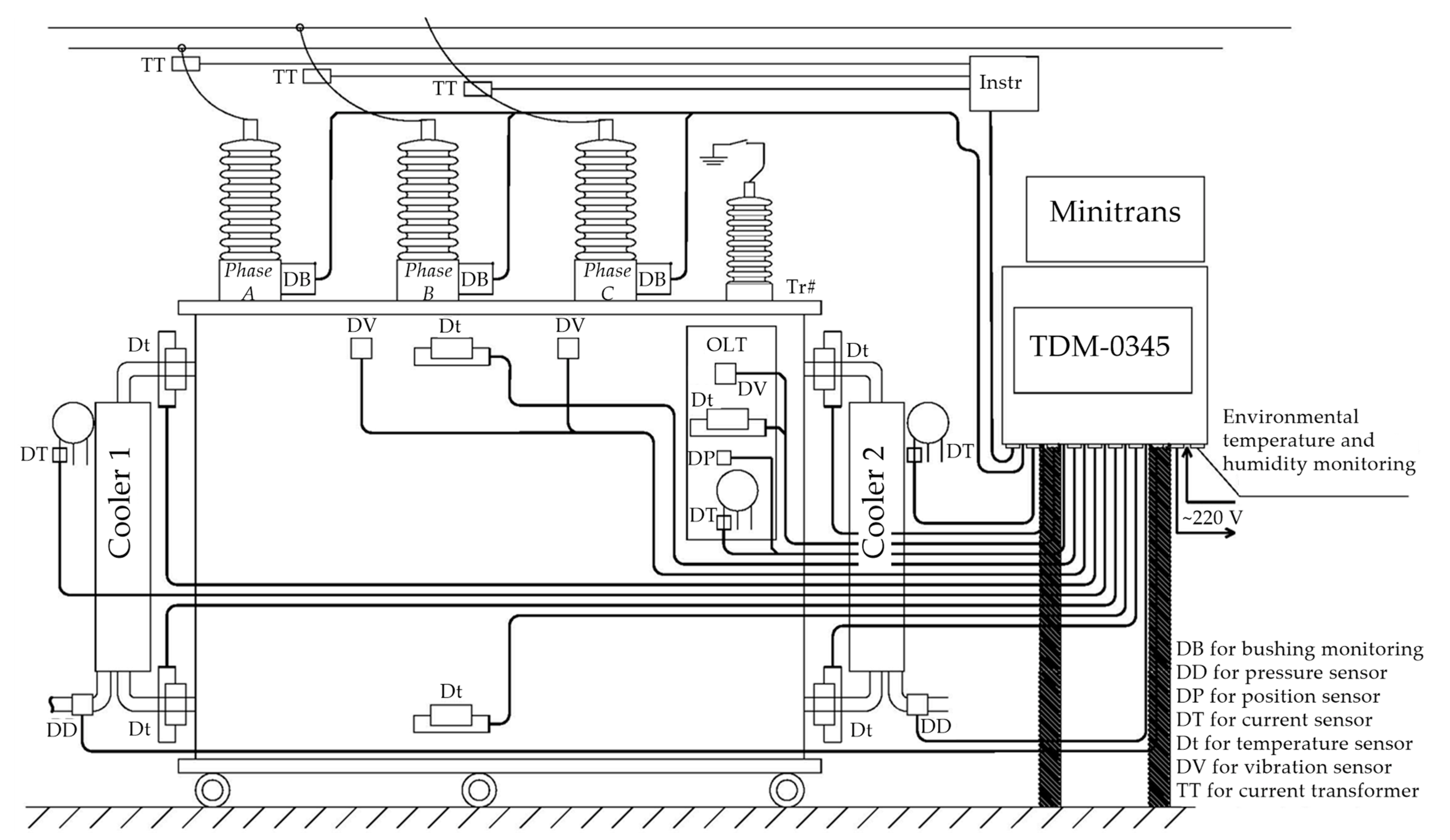
Figure 2 shows a simplified functional diagram of the system. Electrolocation is used to measure the PD readings. The method consists in using DB sensors installed on the PIN terminals of high-voltage bushings; the sensors record the flowing current pulses [63]. Apparent charges are derived from the signal amplitudes, whereas the number of discharges is derived from pulse rates. For details on the system, see [49,64]
The system registers pulses that last ≤640 ns; however, there should be no pulses with an amplitude of >30% of the original pulse amplitude for at least 2560 ns. Failure to meet this requirement classifies the pulse as noise and prevents it from being logged. A PD pulse is considered to periodically repeat if its repetition rate is 0.2 pulses per grid voltage period. The measured apparent charge Q02 is quantitatively proportional to the maximum amplitude of the repeated discharge of pulse U02. It is determined by the linear dependency Q02 = U02/k0, where k0 = 32.56 is a coefficient set in the system configuration. Thus, the values Q02 and U02 are related and are essentially the identical PD readings.
The second PD reading is its power. This parameter is reduced to the integral PDI, which is found by the dependency (1). Both parameters can be used to indirectly assess insulation condition on the basis of the PD readings (Table 2) [65].

2.2. Experimental PD Analysis

In course of the research, we used the newly adopted system to analyze the PD readings in transformer phases from 1 January to 31 December 2015. Figure 3 shows the trends in these readings as logged from 11 February to 22 April 2015 [66]. Figure 3a shows trends in U02 as recorded when monitoring constant discharges; Figure 3b shows trends in PDI.
Table 3 shows normalized limits for each condition category, which can be derived from PD readings [67]. For furnace transformers, the boundary values indicative of the poor insulation condition (U1D and P1D) can be found by the inequalities [49]:
U02 > U1D = 80 mV (Q02 > Q1D = 2.5 nC); PDI > P1D = 60 mW;
For critical condition: (Q2D and P2D)
U02 > U2D = 160 mV (Q02 > Q2D = 5 nC); PDI > P2D = 80 mW.
The limit values determining the object’s state based on the results of the discharge activity control were not determined specifically for furnace transformers, and they are not provided in the regulatory documents. Therefore, the values such as U1D, U02, U2D (etc) were selected the same way as the grid transformer parameters. They are set out in the Methodology Guidelines MU 0634-2006 [67].
Comparison against the dependencies (Figure 3) revealed an expanding destructive process. However, it is not always possible to unambiguously classify the condition of a transformer into one of these categories. Thus, Phase A insulation has the worst condition, as shown in Figure 3a. Its mean charge of 3.2 nC (the solid line) corresponds to poor condition per Table 3. Phase B and Phase C bushings are in a better condition. Their discharge intensity ranges between 0.5−2.5 nC, although the condition is also poor per Table 3.
However, should we analyze the dependencies in Figure 3b, we find Phase C to be in the worst condition. The mean total PD power (solid line) equals ~200 mW, whereas the thresholds are 60 mW and 80 mW. In other phases, however, the insulation is stable and normal. Thus, these readings are confusing with regards to the transformer condition. The reason for this is that Q02 describes the PD amplitude; however, there can be defects, whose expansion increases the number and total power of pulses without affecting the amplitude. This is why PDI is believed to be more defect-sensitive. Authors of several papers, in particular [48], agree.
This analysis proves the relevance of creating an expert system for assessing transformer condition on the basis of its PD readings. To that end, we hereby introduce a generalized indicator: insulation state indicator based on partial discharge (ISIPD). This parameter is a linguistic variable for FL studies.
To test the informativeness of readings, we need to evaluate the diagnostic sensitivity (DSe) of U02 (or Q02) and PDI to the actual transformer condition. Papers [68,69,70] discuss application of a similar metric to analyze the condition of power system equipment; papers [71,72] present a similarly designed comparison of transformer models. However, these developments have not found a practical application yet. It would be relevant to devise a DSe calculation method based on PD readings, and to verify the method experimentally.

3. Materials and Methods

In pursuit of the objectives hereof, the authors were guided by research presented in [73]. The paper proposes a method that applies fuzzy logic to calculate the probability of condition features manifesting (or not manifesting); it returns a formalized result. For condition features, they used gas concentration in the oil as well as thermal imaging-detected overheated spots. Four condition categories were specified, each with a specific range of the selected indicators within the specified limits.
The weakness of the method lies in its assumption that the condition categories are independent. Thus, transformer condition should be described by a set of independent features. However, many features are not [74]. This can be seen, in particular, in the presented analysis of PD readings, see Figure 3.
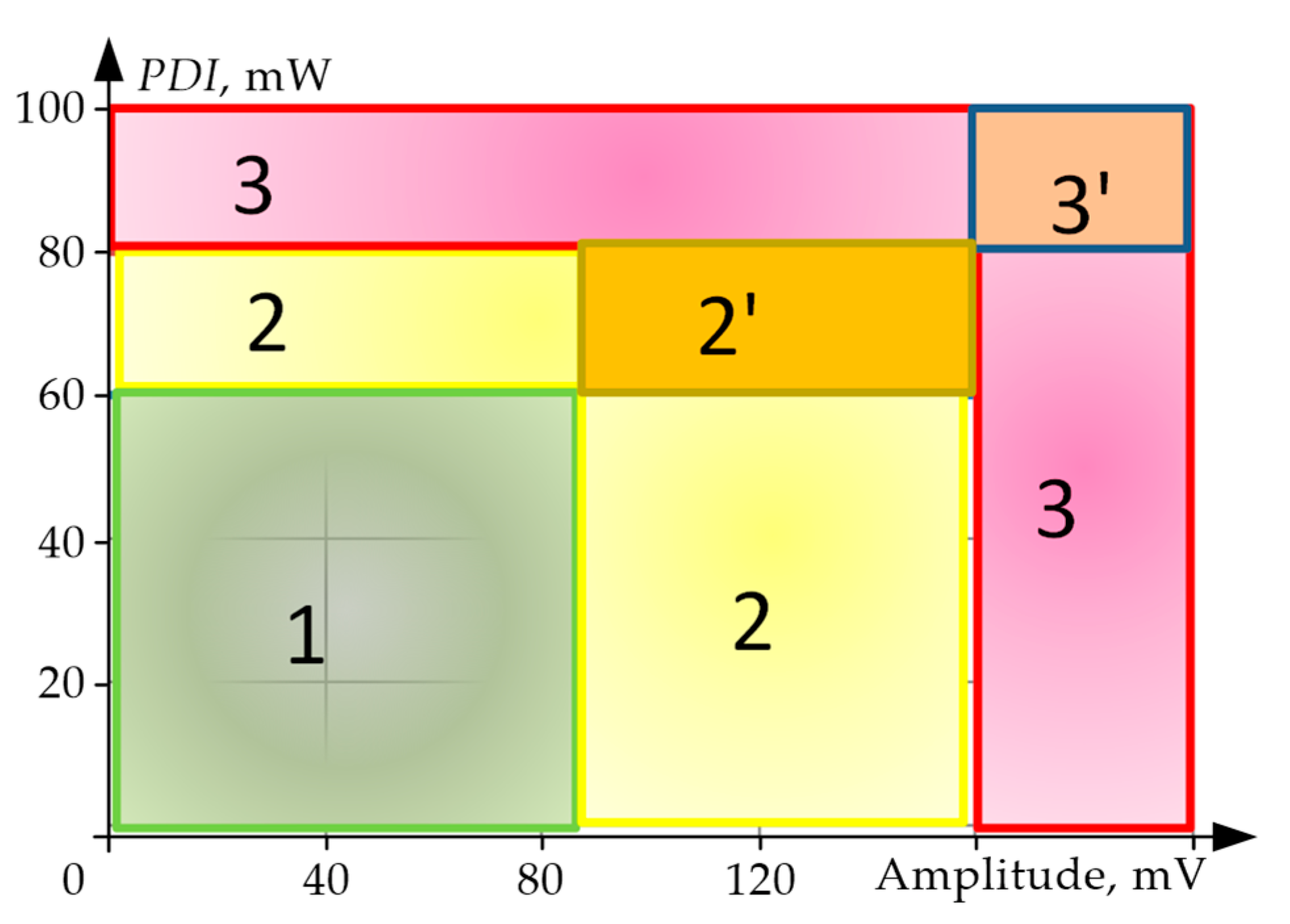
For condition testing, we use the parameters U02 and PDI. A stable reading of any of these characterizes the expansion of insulation defects when compared against the set thresholds. From the standpoint of ordinary crisp sets, insulation condition can be shown as in Figure 4.
In this case, condition can be diagnosed by applying the characteristic function μA(U02, PDI) of membership in one of the three condition sets:
  • normal condition (1) if 0 U 02 < U 1 D or 0 P D I < P   1 D ;
  • poor condition (2) if U 1 D U 02 < U 2 D or P   1 D P D I < P   2 D ;
  • critical condition (3) if U 2 D U 02 or P   2 D P D I .
As can be seen in the figure, there are two more subsets:
  • near-critical condition (2’) if U 1 D U 02 < U 2 D or P   1 D P D I < P   2 D ;
  • emergency condition (3’) if U 2 D U 02 or P   2 D P D I .
In fact, the transition between insulation conditions at a threshold is purely conventional and indefinite. This is why FL is the best condition assessment method. A literature overview reveals many approaches that use fuzzy linguistic variables in decision making. Software that applies fuzzy set theory to address the problems of industrial equipment operation is quite common [75,76]. In this research, we used Fuzzy Logic Toolbox for MatLab.
The degree of a member’s membership in a fuzzy set is determined by the membership function whose specific value is characterized by the membership coefficient. The variables used in fuzzy statements of the subconditions of fuzzy inference rules serve as the input linguistic variables. In turn, the variables used in subconclusion statements are the output linguistic variables. For each of the selected variables, specify corresponding term sets and membership functions.
The input linguistic variables are the maximum PD amplitude and power PDI, whereas the output linguistic variable is ISI PD. Table 4 shows the linguistic variables and their corresponding term sets.
Insulation condition was determined by a matrix of rules as a function of PD readings, see Table 5. The table was used to formulate 9 fuzzy inference rules for condition assessment.
Rule 1if U02 is Low AND PDI is Low, the condition is Normal.
Rule 2if U02 is Medium AND PDI is Low, the condition is Poor
etc.
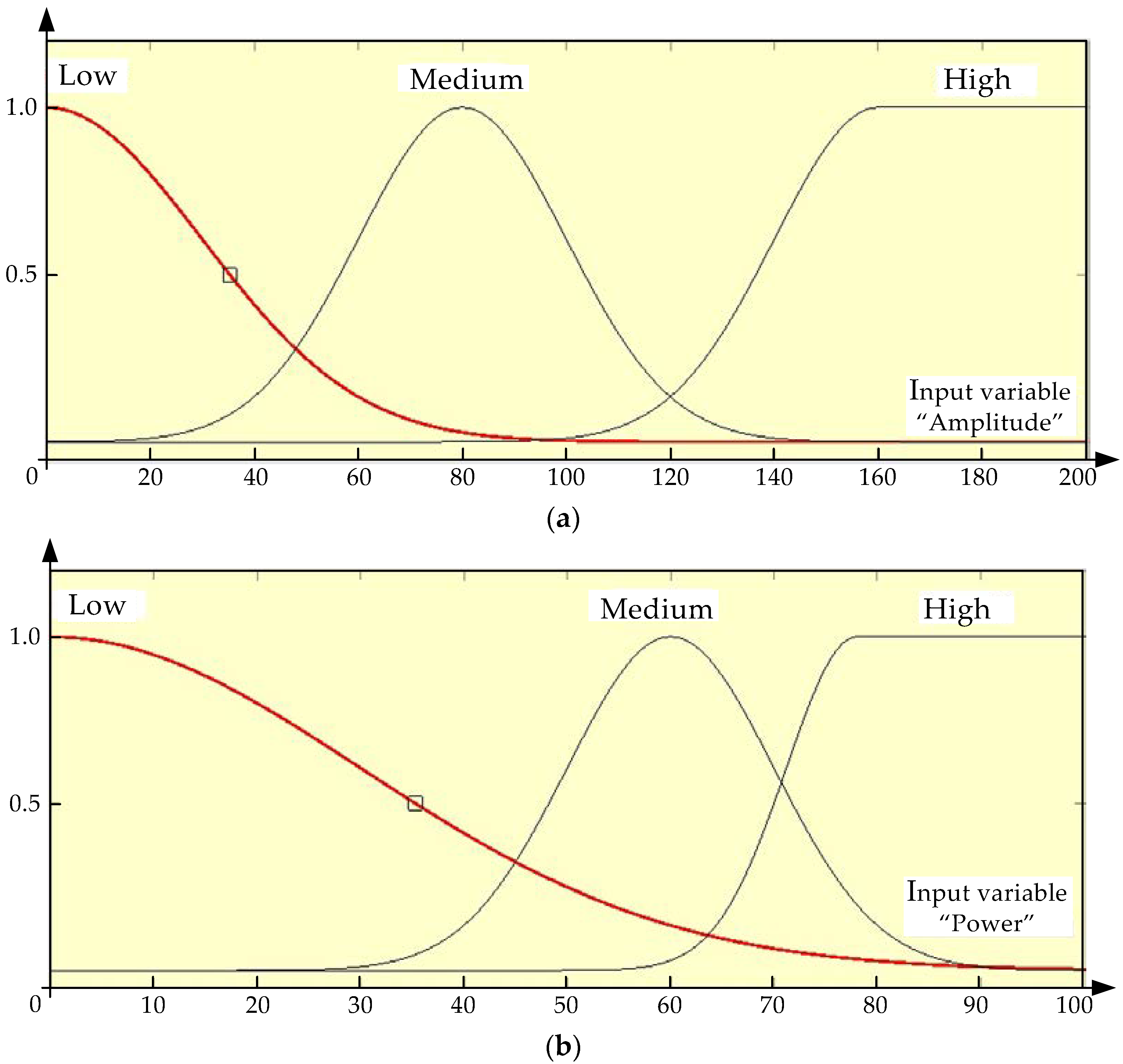
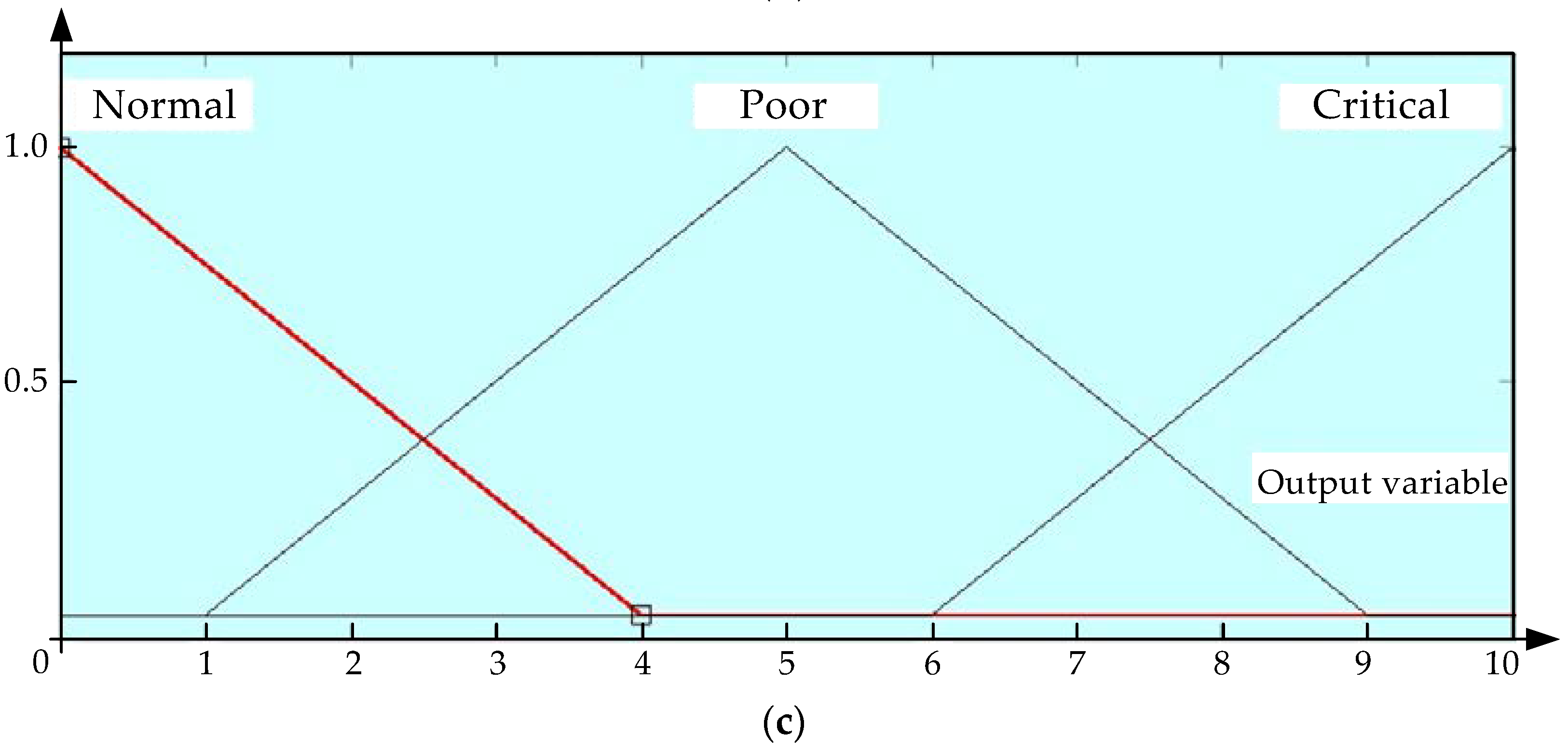
The Gaussian membership function was used for the input variables. This is explained by the natural use of the standard data distribution law relative to the maximum of the membership function for the terms such as ‘low’, ‘medium’, and ‘high’. Besides this, the Gaussian function is smooth and takes non-zero values throughout the applicable domain. The output variable of insulation state relies heavily on the discrete valuation. In this case, it is feasible to use a triangular membership function for the output linguistic variables.
Each condition has a weight Fi, (i = 1, 2, … 9) ranging in [0, 1]. For initial rulemaking, the weights are assumed to equal 1. Further optimization of the fuzzy inference rule base and its adjustment for the real-world data led to adjustments in the weights.
For fuzzy models, the input signals are the U02 and PDI readings that uniquely determine the inputs. That means that for the given inputs, the outputs should be uniquely determined as well. These sets interact through a fuzzy system that has an input fuzzifier and an output defuzzifier [77].
For the inputs, the assumption is that the maximum PD amplitude ranges from 0 to 1.25∙U2D = 200 mV, and the PD power ranges from 0 to 1.25∙P2D =100 mW. For the output variable Insulation Condition, the range is 0 to 10 points. The input variables have three functions named Low, Medium, and High. Assume that the first two variables are Gaussian,
g a u s s m f ( x ,   σ ,   c ) = exp x c σ 2 ,
whereas the last variable is a two-sided Gaussian membership function
g a u s s 2 m f ( x ,   σ 1 ,   c 1 , σ 2 ,   c 2 ) ,
where c is the mathematical expectation; σ is the standard deviation; and σ1, c1, σ2, c2 are the Gaussian function parameters that determine the membership function curve shape to the left and to the right of the modal value.
For the output variables, set three triangular membership functions named Normal, Poor, and Critical. Poor condition is set at 5 points, and critical condition corresponds to 7.5 points. Description of a triangular membership function is known
t r i m f ( x ,   a ,   b ,   c ) = 0 ,   x a x a b a , a x b c x c b , b x c 0 , x c .
where a, b, c are numerical parameters whereby a ≤ b ≤ c.
Table 6 shows the membership function specifications; Figure 5 shows the functions themselves for the input and output variables.
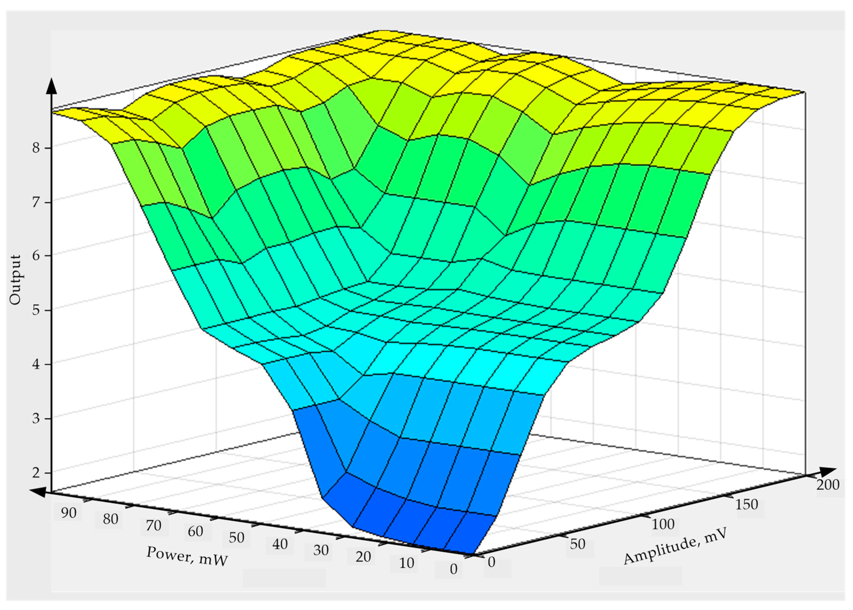
Figure 6 shows a surface diagram based on this data and the selected membership functions; the diagram shows how the linguistic inputs affect the linguistic output ISIPD. This surface was produced by applying fuzzy inference rules to assess operational hazard with the given defuzzifier (Mamdani algorithm). For the selected membership functions, the output variable had a high of 8.7 points and a low of 1.3 points. As specified in the model, poor condition corresponded to ~5 points, and critical condition corresponded to ~7.5 points. Matlab evalfis can be used to obtain fuzzy inference function values to further plot the output parameter as a function of one of the input variables.

4. Implementation

4.1. Example of Generalized Indicator-Based Transformer Condition Assessment

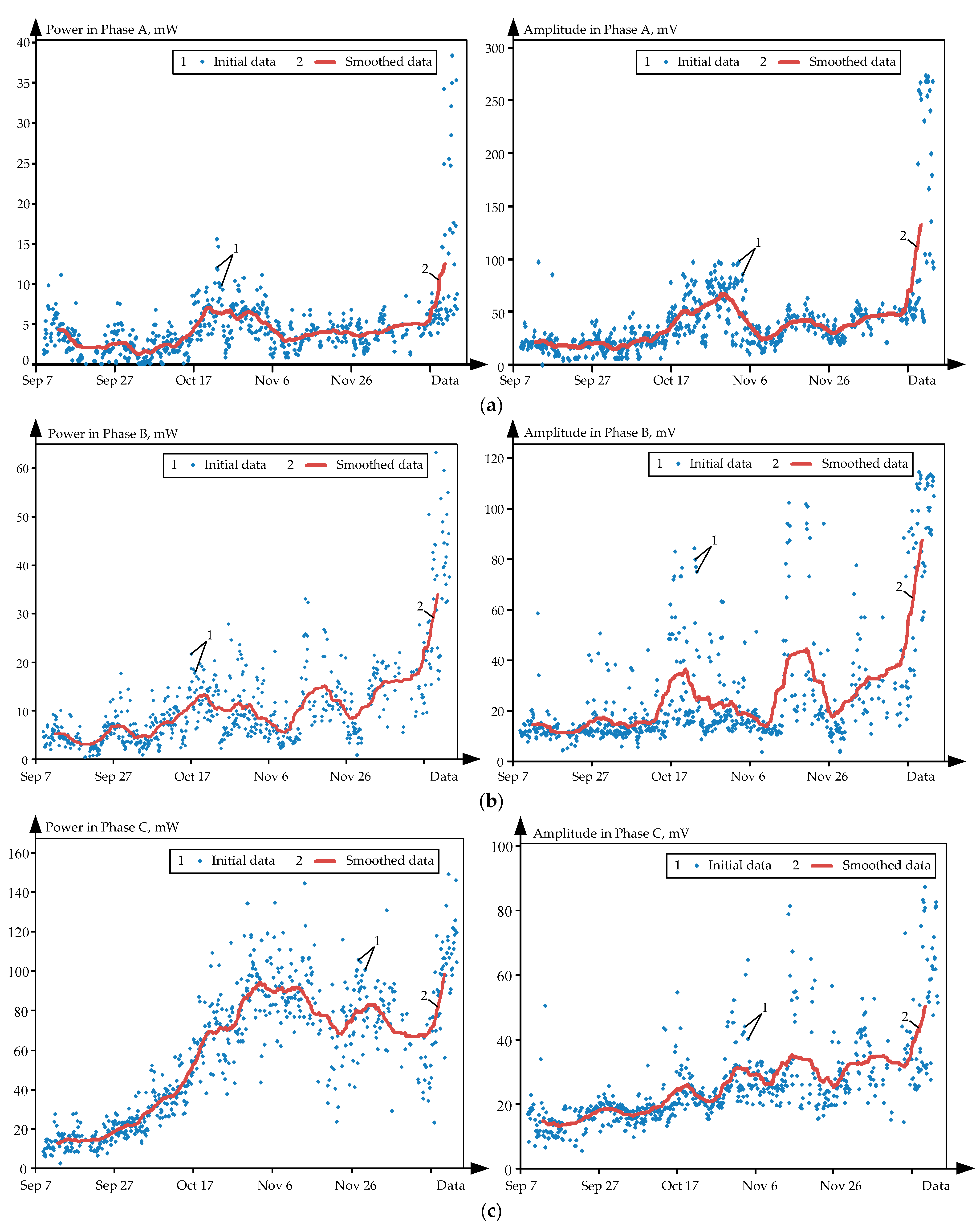
Figure 7 shows the online readings of PD amplitude U02 and PDI for the tested transformer as points. Input data were smoothed by moving the average over 50 points and are shown as solid lines [49]. These data was collected from 9 September to 22 December 2016; the sample was ~650 points for each phase. Such late data retrieval was due to the fact that it was in this period that the transformer’s condition went from normal to poor. Timely diagnosis prevented its escalation to critical. No similar situations have arisen since. This is why these trends in PD readings, although not being freshly collected data, do contain important (and, to an extent, unique) diagnostic information. To further support this statement, we hereby report that we have not been able to find similar data in the literature.
In the data sample, a drastic increase in PD intensity can be observed in all phases from late September to early October. PDI rose the most in Phase C, see Figure 7c. Thus, on ~18 October it exceeded 60 mW (the poor condition threshold); on 28 October, it went past 80 mW (the critical condition threshold). In late October, PD power and amplitude began decreasing in Phases A and B, see Figure 7a,b; however, they kept increasing monotonically in Phase C. This continued until Nov 3 (PDI ≈ 98 mW); then, the process stabilized in Phase C, but the power settled at a higher level. After a relatively flat segment in the PDI trend, PD intensity began to rise drastically, starting on ~15 December. In all phases, PD power and amplitude rose 1.5-2-fold. In Phases A and B, there was an increase in amplitude (U02 > 80 mV), whereas in Phase C, power rose to poor and then to critical levels (PDI > 80 mW).
Figure 8 shows a change in ISIPD in phases over the same timeframe. To that end, PD power and amplitude readings were processed in Fuzzy Logic Toolbox for MatLab. Smoothed data shown in Figure 7 as solid lines were used as input variables.
Broken lines show poor and critical condition levels (5 points and 7.5 points), as validated above. As can be seen in Figure 7 and Figure 8, Phase C is the most ‘problematic’ one. It is in this phase where, starting from ~18 October, we can observe a poor condition that becomes critical in 10 days. ISIPD then drops to ~5 points, beginning to rise again on 13–15 December; it simultaneously increases in Phases A and B. By 20 December, Phase B readings reached a poor condition, whereas Phases A and C reached a critical condition.

4.2. PD Readings Sensitivity Testing

Pursuant to the objectives, we further proceeded to test the reliability of U02 and PDI readings as insulation condition indicators. Tests relied on the aforesaid indicator DSe. Calculations were based on experimental data. The developed methodology included the following steps.
  • For quantification, it is proposed to use a generalized indicator descriptive of the hazard of PD for insulation. In this case, such an indicator has to be a normalized characteristic of the informative parameters Y ¯ i with respect to the difference between the poor/critical condition threshold ( Y j D ) and normal (background) readings. Y i 0
    X ¯ i = Y ¯ i Y i 0 Y j D Y i 0 .
    Normalized values ( X ¯ i ) ensure that the requirements of dimensionlessness and 0–1 rating scale uniformity are met at Y i 0 Y ¯ i Y i D .
  • Since PD activity is measured by reading the voltage U02 and the power PDI, they correspond to two normalized indicators: XU and XP. For the parameter of their co-effect, we suggest the geometric mean hereinafter referred to as PD Activity Level.
    L P D = X U X P .
    Given the expressions (5) and (6)
    L P D = P i P 0 P j D P 0 U i U 0 U j D U 0 ,
    where P0 and U0 are the initial PDI and U02, PjD, UjD are the thresholds for poor condition (j = 1) and critical condition (j = 2).
  • Calculate the mean of each signal over the specified timeframe
    Y ¯ i = 1 N k = 1 N X k .
    or the Euclidean norm
    Y ¯ i = k = 1 N X k 2 ,
    where N is the number of points for the specified timeframe.
    These parameters need to be introduced because Pi and Ui are random values that can deviate substantially from the means. In order to prevent random scatter, assume values averaged over a small interval, which are calculated by the dependencies (8) or (9).
  • To find out which of the parameters (PDI or U02) is more sensitive to insulation condition, we hereby suggest considering how the difference in their normalized values changes over time:
    Δ X = P i P 0 P j D P 0 U i U 0 U j D U 0 .
When critical condition is observed, calculate the magnitude and sign of ΔX from the readings. If a high-PD phase is confirmed to have a defect as detected, e.g., by transformer disassembly, a positive ΔX signifies a higher influence of PDI, whereas the minus sign signifies a more pronounced influence of the amplitude U02.

5. Results and Discussion

The method was tested on the online readings shown in Figure 7 as initial data. As shown above, the condition of the object changed from normal to critical in this range. Initial PDI and U02 values (shown as P0 and U0) were sampled by averaging a 7-day data span from 9 September to 15 September 2016. As in the previous case, data were smoothed by moving the average.
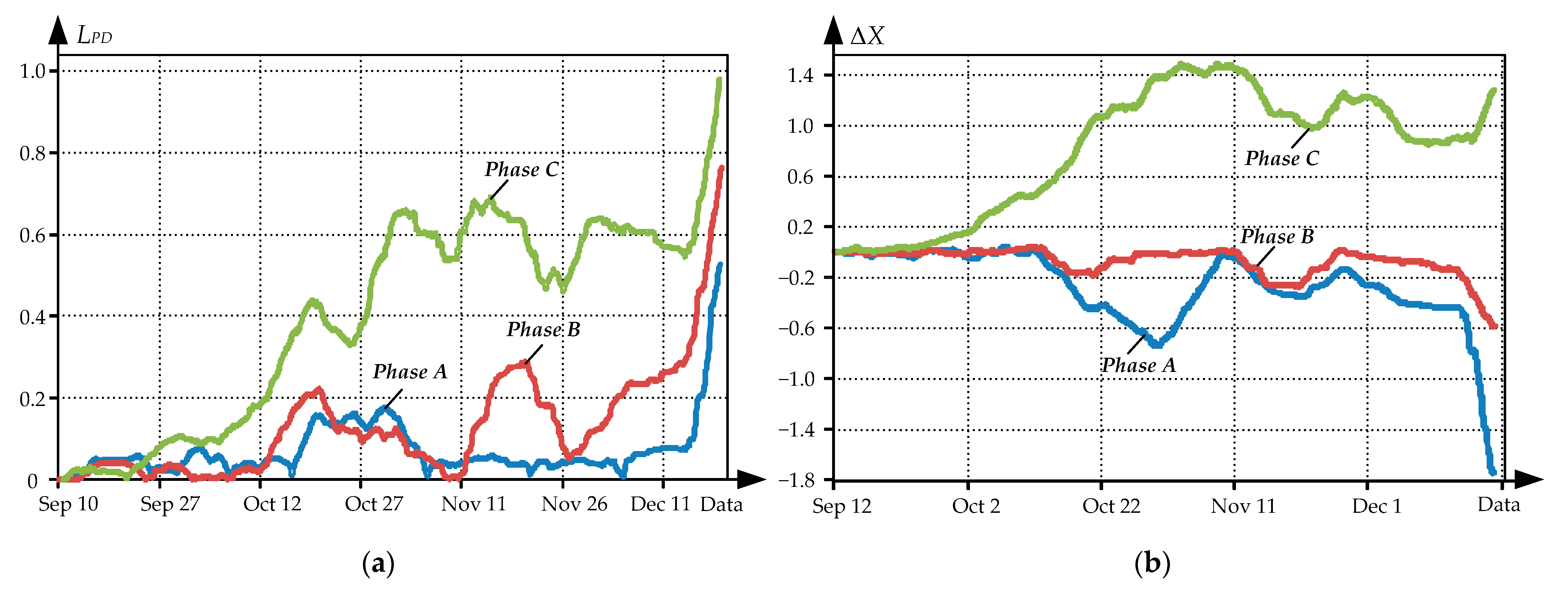
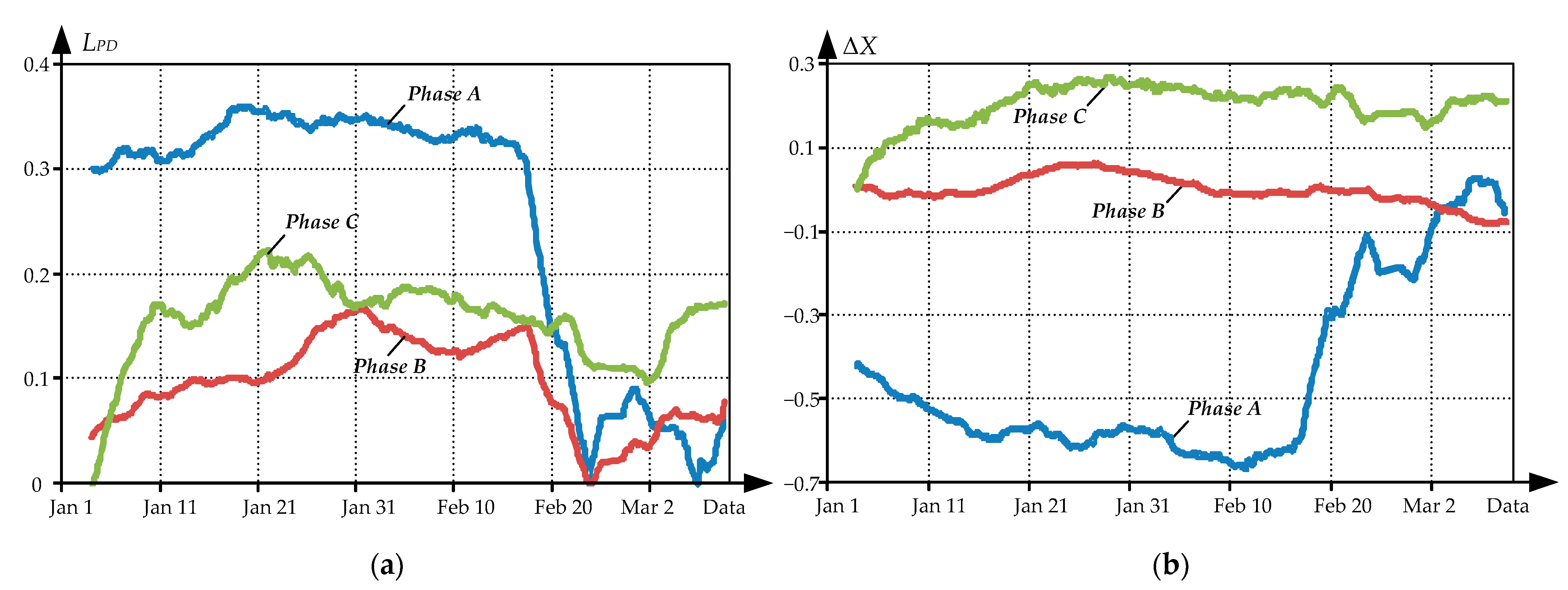
Figure 9a shows trends in LPD for three phases as calculated by the proposed method. Calculations were based on the averaged values P ¯ i and U ¯ 02 i , as calculated by the Formula (9) for timeframes of 1 to 3 h. Figure 9b shows trends in the difference ΔX of normalized power and amplitude as calculated by the dependency (10). Apparently, Phase C had the greatest activity, which was rising significantly starting from mid-October.
Trend analysis leads to the following conclusions:
  • Over the time when the transformer was in a normal condition (from the initial readings to ~10 October), PD activity level (Figure 9a) did not change significantly for any phase. Therefore, neither reading (PDI or U02) could be considered conclusive.
  • A further positive increase in ΔX signified a substantial increase in the effect of PDI on discharge activity. Therefore, from ~10 October until mid-December, i.e., when the condition was poor, PDI would be the more informative parameter.
  • Once the transformer’s condition became critical (after ~18 October), the discharge activity index LPD (Figure 9a) went up in all phases. That being said, an increased PD intensity was reported by the sensors installed at the PIN terminals of three high-voltage bushings.
  • After ~18 October, in light of the looming emergency, it became again difficult to choose the preferable diagnostic parameter: Figure 9b shows a positive change in ΔX in Phase C and a negative change in Phases A and B.
  • In poor condition, the greatest increase in discharge activity was observed in Phase C, whereas the activity in Phases A and B was not significant, see Figure 9a. It would be therefore logical to assume that the critical condition was caused by an expanding defect in Phase C, see proof below.
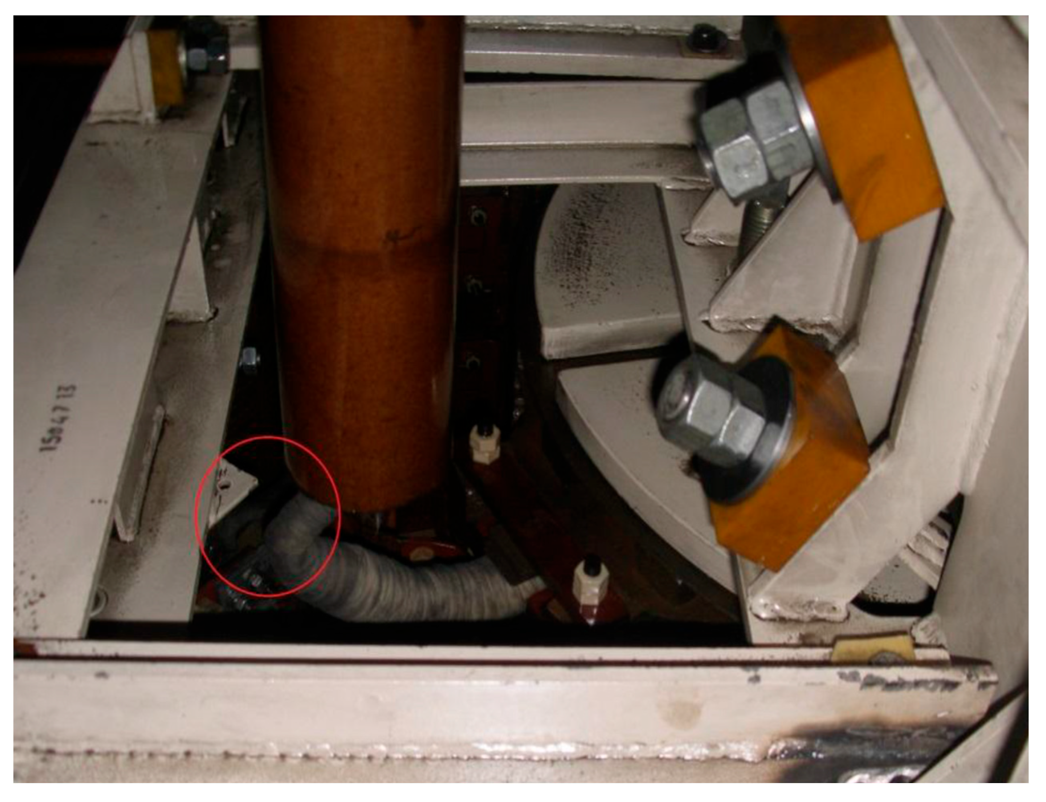
Given the situation, the ladle furnace was shut down on 23 December 2016. Partial disassembly revealed a defect, see Figure 10. It was caused by an inappropriate bend in the wire connecting the high-voltage bushing to the primary winding. As a result, Phase C output of the high-voltage winding was dangerously close to the acute angle of the plate welded to the booster transformer beam. Given that charge concentrates on pointed surfaces, PDs intensified.
After the issue was fixed, we analyzed PD readings dated 1 January to 12 March 2017. 500 points were sampled for each phase, smoothed by moving the average over 50 points. Minimum values of the entire timeframe were picked for background values, which coincided with the values averaged over the period from 9–15 September 2016. These data were used to plot the trends shown in Figure 9.
Figure 11a shows trends in PD Activity Level similar to the curves in Figure 9a. They show LPD values to be relatively low in all phases, decreasing further after 15 February and never rising above 0.2 again. Figure 11b shows trends in normalized power and amplitude difference; apparently, compared to Figure 9b, the ΔX(t) dependencies change in a narrower range in all phases. This leads to the conclusion that the PD-raising fault had been fixed.

6. Conclusions and Future Work

Thus, this paper proposes a method for convolution of two particular PD readings into a generalized indicator; the method uses fuzzy logic. For the first time, a generalized determinate insulation state indicator based on partial discharge was rationalized. It allows for the monitoring of the insulation state based on the results of online monitoring of the apparent charge and the PD power.
The authors developed a procedure to assess the diagnostic sensitivity of the PD parameters to the changes in the technical state. The diagnostic sensitivity of parameters such as U02 and PDI to the actual state of the transformer was used as the criterion. The key features of the procedure include the following:
Calculating the standardized indicator to satisfy the requirements for the grade scale zero-dimensionality and uniformity.
Determining the geometric average PD activity level;
Calculating the average value for each of the signals within the set interval (or Euclidean norm);
Determining the sensitivity of the PDI and U02 to the insulation state in terms of the size and sign of the standardized indicator.
Based on the analysis of the parameter trends identified during the changing of the state from normal to pre-emergency, the authors proved the consistency of using the suggested procedure to determine the technical state. The authors provided a practical example of defect localization that confirmed the efficiency of technical state assessment for the high-voltage equipment using the ISIPD parameter.
The effects of PD amplitude and power are combined into a single deterministic parameter: an insulation condition indicator based on PD readings. This is a normalized value that indicates insulation condition.
Logic rules were compiled with the weights Fi being equal to 1. These values are subject to adjustment when optimizing the fuzzy inference rule base. Additional experimental data allow the adjustment of the weights to rank the rules by whether PDs can render the transformer unusable.
The generalized indicator value has been proven theoretically and experimentally to be relevant for predicting poor or critical condition of a transformer. Continuous PD monitoring of a transformer in poor condition and the further examination by the repair crew prove the statement above.
A comparison of trends in normalized power (PDI) and PD(U02) difference showed PDI to be more sensitive for the assessment (and prediction) of insulation wear in normal condition.
It seems promising to further advance this method in order to adopt integrated diagnostics. Thus, PD monitoring would be advisable in combination with DGA. This will enable more informative diagnosis and more reliable condition assessment.
Another area of focus consists in developing methods for localization and identification of transformer faults. A literature overview shows that methods based on locating PD hotspots and comparing their location to the equipment layout (windings, OTLCs, etc.) in the transformer tank [78,79,80] are more promising.
Since furnace transformers are among the most complex pieces of power equipment, fuzzy diagnostics tested on them could find much broader use. They are recommendable in particular for online monitoring of high-voltage switchgear equipment: overvoltage protections, high-voltage circuit breakers, bushing insulators, etc. Such systems have been developed and implemented on the closed 110-kV switchgear in the electric steelmaking shop of the steelworks. The developed method will have a specific application in these systems.
Overall, the research conducted promotes the further development of the predictive control theory for the state of high-voltage equipment. It also supports the practical implementation of the smart furnace transformer concept. The development and introduction of smart online state monitoring systems is a relevant IIoT-based upgrade area for the metal industry.

Author Contributions

Conceptualization, A.S.K. and A.A.R.; methodology, I.M.Y.; software, E.A.K.; validation, N.N.D., I.V.L. and E.A.K.; formal analysis, A.S.K. All authors have read and agreed to the published version of the manuscript.

Funding

This research received no external funding.

Institutional Review Board Statement

Not applicable.

Data Availability Statement

Not applicable.

Conflicts of Interest

The authors declare no conflict of interest.

References

  1. Guide on Transformer Intelligent Condition Monitoring (TICM) Systems. Available online: https://pureportal.strath.ac.uk/en/publications/guide-on-transformer-intelligent-condition-monitoring-ticm-system (accessed on 24 March 2022).
  2. Bohatyrewicz, P.; Mrozik, A. The Analysis of Power Transformer Population Working in Different Operating Conditions with the Use of Health Index. Energies 2021, 14, 5213. [Google Scholar] [CrossRef]
  3. Naderian, A.; Cress, S.; Piercy, R.; Wang, F.; Service, J. An approach to determine the health index of power transformers. In Proceedings of the Conference Record of the IEEE International Symposium on Electrical Insulation, Vancouver, BC, Canada, 9–12 June 2008; pp. 192–196. [Google Scholar] [CrossRef]
  4. Kittan, S.; Kornhuber, S.; Kastel, P.; Nitsche, G.; Valtin, G.; Weise, M. Review and implementation of transformer health index methods in line with the development of a condition assessment tool. In Proceedings of the International Conference on Diagnostics in Electrical Engineering Diagnostika, Pilsen, Czech Republic, 4–7 September 2018; pp. 1–4. [Google Scholar] [CrossRef]
  5. Arshad, M.; Islam, S.; Khaliq, A. Fuzzy logic approach in power transformers management and decision making. Dielectr. Electr. Insul. IEEE Trans. 2014, 21, 2343–2354. [Google Scholar] [CrossRef]
  6. Khramshin, V.R.; Evdokimov, S.A.; Nikolaev, A.A.; Nikolaev, A.A.; Karandaev, A.S. Monitoring technical state of the power transformers is a necessary condition of the smart-grid technology introduction within the industrial electric networks. In Proceedings of the IEEE NW Russia Young Researchers in Electrical and Electronic Engineering Conference (EIConRusNW), St. Petersburg, Russia, 2–4 February 2015; pp. 214–220. [Google Scholar] [CrossRef]
  7. Singh, J.; Aggarwal, S. Distribution transformer monitoring for smart grid in India. In Proceedings of the IEEE 1st International Conference on Power Electronics, Intelligent Control and Energy Systems (ICPEICES), Delhi, India, 4–6 July 2016; pp. 1–6. [Google Scholar] [CrossRef]
  8. Tran, Q.T.; Davies, K.; Roose, L.; Wiriyakitikun, P.; Janjampop, J.; Riva Sanseverino, E.; Zizzo, G. A Review of Health Assessment Techniques for Distribution Transformers in Smart Distribution Grids. Appl. Sci. 2020, 10, 8115. [Google Scholar] [CrossRef]
  9. Thangiah, L.; Ramanathan, C.; Chodisetty, L.S. Distribution transformer condition monitoring based on edge intelligence for industrial IoT. In Proceedings of the IEEE 5th World Forum on Internet of Things (WF-IoT), Limerick, Ireland, 15–18 April 2019; pp. 733–736. [Google Scholar] [CrossRef]
  10. Izidoro, C.L.; Rocha, A.O.; Spacek, J.D.; Neto, J.M.; Spacek, A.D.; Ando Junior, O.H. Development of an Industrial IoT Based Monitoring System for Voltage Regulators. IEEE Lat. Am. Trans. 2021, 19, 1410–1416. [Google Scholar] [CrossRef]
  11. Nicolaou, C.; Mansour, A.; Jung, P.; Schellenberg, M.; Würde, A.; Walukiewicz, A.; Kahlen, J.N.; Shekow, M.; Laerhoven, K.V. Intelligent, sensor-based condition monitoring of transformer stations in the distribution network. In Proceedings of the Smart Systems Integration (SSI), Grenoble, France, 27–29 April 2021; pp. 1–4. [Google Scholar] [CrossRef]
  12. Rediansyah, D.; Prasojo, R.A.; Suwarno; Abu-Siada, A. Artificial Intelligence-Based Power Transformer Health Index for Handling Data Uncertainty. IEEE Access 2021, 9, 150637–150648. [Google Scholar] [CrossRef]
  13. Refaat, S.S.; Abu-Rub, H. Smart grid condition assessment: Concepts, benefits and developments. Power Electron. Drives 2016, 2, 147–163. [Google Scholar] [CrossRef]
  14. Wang, G.; Liu, Y.; Chen, X.; Yan, Q.; Sui, H.; Ma, C.; Zhang, J. Power transformer fault diagnosis system based on Internet of Things. EURASIP J. Wirel. Commun. Netw. 2021, 2021, 21. [Google Scholar] [CrossRef]
  15. Chakravorti, S.; Dey, D.; Chatterjee, B. Recent trends in the condition monitoring of transformers. In Power Systems; Springer: London, UK, 2013. [Google Scholar] [CrossRef]
  16. Khan, M.A.; Zakir, H.Z.; Hasmat, M.H. Recent Trends in Power Transformer Fault Diagnosis and Condition Assessment. Bull. Electr. Eng. Inform. 2013, 2, 95–104. [Google Scholar] [CrossRef]
  17. Guo, C.; Dong, M.; Yang, X.; Wang, W. A Review of on-line condition monitoring in power system. In Proceedings of the IEEE 8th International Conference on Advanced Power System Automation and Protection (APAP), Xi’an, China, 21–24 October 2019; pp. 634–637. [Google Scholar] [CrossRef]
  18. Singh, R.P.; Sonawane, A.V.; Satpute, M.S.; Shirsath, D.Y.; Thakre, M. A review on traditional methods of condition monitoring of transformer. In Proceedings of the International Conference on Electronics and Sustainable Communication Systems (ICESC), Coimbatore, India, 2–4 July 2020; pp. 1144–1152. [Google Scholar] [CrossRef]
  19. Žarković, M.; Stojković, Z. Analysis of artificial intelligence expert systems for power transformer condition monitoring and diagnostics. Electr. Power Syst. Res. 2017, 149, 125–136. [Google Scholar] [CrossRef]
  20. Chaves, T.R.; Martins, M.A.I.; Martins, K.A.; de Macedo, A.F.; de Francisci, S. Application Study in the Field of Solutions for the Monitoring Distribution Transformers of the Overhead Power Grid. Energies 2021, 14, 6072. [Google Scholar] [CrossRef]
  21. Tenbohlen, S.; Coenen, S.; Djamali, M.; Müller, A.; Samimi, M.H.; Siegel, M. Diagnostic Measurements for Power Transformers. Energies 2016, 9, 347. [Google Scholar] [CrossRef]
  22. Karandaev, A.S.; Evdokimov, S.A.; Sarlibaev, A.A.; Lednov, R.A. Requirements to the Monitoring System of Ultra-High Power Electric Arc Furnace Transformer Performance. Russ. Internet J. Ind. Eng. 2013, 2, 58–68. [Google Scholar]
  23. Lozynskyy, A.; Kozyra, J.; Łukasik, Z.; Kuśmińska-Fijałkowska, A.; Kutsyk, A.; Paranchuk, Y.; Kasha, L. A Mathematical Model of Electrical Arc Furnaces for Analysis of Electrical Mode Parameters and Synthesis of Controlling Influences. Energies 2022, 15, 1623. [Google Scholar] [CrossRef]
  24. Evdokimov, S.A. Technical state monitoring of transformer OLTC of ultrahigh power electric arc furnace. Bull. South-Ural State Univ. Power Eng. 2014, 14, 22–30. [Google Scholar]
  25. Karandaev, A.S.; Evdokimov, S.A.; Khramshin, V.R.; Lednov, R.A. Diagnostic Functions of a System for Continuous Monitoring of the Technical Condition of the Transformers of Arc Steelmaking Furnaces. Metallurgist 2014, 58, 655–663. [Google Scholar] [CrossRef]
  26. Karandaev, A.S.; Evdokimov, S.A.; Khramshin, V.R.; Sarlybaev, A.A. System for Real-Time Monitoring of the Technical State of a Transformer on an Ultrahigh-Power Electric-Arc Steelmaking Furnace. Metallurgist 2014, 58, 872–879. [Google Scholar] [CrossRef]
  27. Fernández, J.C.; Corrales, L.B.; Hernández, F.H.; Benítez, I.F.; Núñez, J.R. A fuzzy logic proposal for diagnosis multiple incipient faults in a power transformer. In Progress in Artificial Intelligence and Pattern Recognition; Lecture Notes in Computer Science, 13055; Springer: Cham, Switzerland, 2021; pp. 187–198. [Google Scholar] [CrossRef]
  28. Apte, S.; Somalwar, R.; Wajirabadkar, A. Incipient fault diagnosis of transformer by DGA using fuzzy logic. In Proceedings of the IEEE International Conference on Power Electronics, Drives and Energy Systems (PEDES), Chennai, India, 18–21 December 2018; pp. 1–5. [Google Scholar] [CrossRef]
  29. Ahmed, M.R.; Geliel, M.A.; Khalil, A. Power transformer fault diagnosis using fuzzy logic technique based on dissolved gas analysis. In Proceedings of the 21st Mediterranean Conference on Control and Automation, Platanias, Greece, 25–28 June 2013; pp. 584–589. [Google Scholar] [CrossRef]
  30. Mharakurwa, E.T.; Nyakoe, G.N.; Akumu, A.O. Power Transformer Fault Severity Estimation Based on Dissolved Gas Analysis and Energy of Fault Formation Technique. J. Electr. Comput. Eng. 2019, 2019, 9674054. [Google Scholar] [CrossRef] [Green Version]
  31. Taha, I.B.M.; Ibrahim, S.; Mansour, D.-E.A. Power Transformer Fault Diagnosis Based on DGA Using a Convolutional Neural Network with Noise in Measurements. IEEE Access 2021, 9, 111162–111170. [Google Scholar] [CrossRef]
  32. Ranga, C.; Chandel, A.K.; Chandel, R. Expert system for condition monitoring of power transformer using fuzzy logic. J. Renew. Sustain. Energy 2017, 9, 044901. [Google Scholar] [CrossRef]
  33. Aghaei, J.; Gholami, A.; Shayanfar, H.A.; Dezhamkhooy, A. Dissolved gas analysis of transformers using fuzzy logic approach. Eur. Trans. Electr. Power 2009, 20, 630–638. [Google Scholar] [CrossRef]
  34. Poonnoy, N.; Suwanasri, C.; Suwanasri, T. Fuzzy Logic Logic Approach to Dissolved Gas Analysis for Power Transformer Failure Index and Fault Identification. Energies 2021, 14, 36. [Google Scholar] [CrossRef]
  35. Su, C.Q. A new fuzzy logic method for transformer incipient fault diagnosis. In Proceedings of the IEEE International Conference on Fuzzy Systems (FUZZ-IEEE), Vancouver, BC, Canada, 24–29 July 2016; pp. 324–327. [Google Scholar] [CrossRef]
  36. Malik, H.; Tarkeshwar; Jarial, R.K. An expert system for incipient fault diagnosis and condition assessment in transformers. In Proceedings of the International Conference on Computational Intelligence and Communication Networks, Gwalior, India, 7–9 October 2011; pp. 138–142. [CrossRef]
  37. Abu-Siada, A.; Hmood, S.; Islam, S. A new fuzzy logic approach for consistent interpretation of dissolved gas-in-oil analysis. IEEE Trans. Dielectr. Electr. Insul. 2013, 2, 2343–2349. [Google Scholar] [CrossRef] [Green Version]
  38. Alqudsi, A.; El-Hag, A. Application of Machine Learning in Transformer Health Index Prediction. Energies 2019, 12, 2694. [Google Scholar] [CrossRef] [Green Version]
  39. Husain, Z. Fuzzy Logic Expert System for Incipient Fault Diagnosis of Power Transformers. Int. J. Electr. Eng. Inform. 2018, 10, 300–317. [Google Scholar] [CrossRef]
  40. Genc, S.; Karagol, S. Fuzzy logic application in DGA methods to classify fault type in power transformer. In Proceedings of the International Congress on Human-Computer Interaction, Optimization and Robotic Applications (HORA), Ankara, Turkey, 26–28 June 2020; pp. 1–4. [Google Scholar] [CrossRef]
  41. Luo, Y.; Li, Z.; Wang, H. A Review of Online Partial Discharge Measurement of Large Generators. Energies 2017, 10, 1694. [Google Scholar] [CrossRef] [Green Version]
  42. Muhr, M.; Schwarz, R. Partial discharge measurement as a diagnostic tool for HV-equipments. In Proceedings of the IEEE 8th International Conference on Properties and Applications of Dielectric Materials, Bali, Indonesia, 26–30 June 2006. [Google Scholar] [CrossRef]
  43. Baker, P.C.; Stephen, B.; Judd, M.D. Compositional Modeling of Partial Discharge Pulse Spectral Characteristics. IEEE Trans. Instrum. Meas. 2013, 62, 1909–1916. [Google Scholar] [CrossRef] [Green Version]
  44. Commission, I.E. IEC 60270: High-Voltage Test Techniques-Partial Discharge Measurements. Available online: https://webstore.iec.ch/publication/1247 (accessed on 24 March 2022).
  45. Gianoglio, C.; Ragusa, E.; Gastaldo, P.; Gallesi, F.; Guastavino, F. Online Predictive Maintenance Monitoring Adopting Convolutional Neural Networks. Energies 2021, 14, 4711. [Google Scholar] [CrossRef]
  46. Lumba, L.A.; Khayam, U.; Lumba, L.S. Application of fuzzy logic for partial discharge pattern recognition. In Proceedings of the International Conference on Electrical Engineering and Informatics (ICEEI), Bandung, Indonesia, 9–10 July 2019; pp. 210–215. [Google Scholar] [CrossRef]
  47. Seifi, S.; Werle, P.; Shayegani Akmal, A.A.; Mohseni, H.; Borsi, H. A feasibility study on estimating induced charge of partial discharges in transformer windings adjacent to its origin. Int. J. Electr. Power Energy Syst. 2021, 129, 106899. [Google Scholar] [CrossRef]
  48. Rusov, V.A. Measurement of Partial Discharges in Insulation of High-Voltage Equipment; UrGUPS: Yekaterinburg, Russia, 2011; 367p. [Google Scholar]
  49. Karandaeva, O.I.; Yakimov, I.A.; Filimonova, A.A.; Gartlib, E.A.; Yachikov, I.M. Stating Diagnosis of Current State of Electric Furnace Transformer on the Basis of Analysis of Partial Discharges. Machines 2019, 7, 77. [Google Scholar] [CrossRef] [Green Version]
  50. NPP Maintenance and Repair Guidelines. Concern ROSENERGOATOM. Available online: https://files.stroyinf.ru/Data2/1/4293777/4293777767.pdf (accessed on 24 March 2022).
  51. Alvarez, F.; Ortego, J.; Garnacho, F.; Sanchez-Uran, M.A. A clustering technique for partial discharge and noise sources identification in power cables by means of waveform parameters. IEEE Trans. Dielectr. Electr. Insul. 2016, 23, 469–481. [Google Scholar] [CrossRef] [Green Version]
  52. Radionov, A.A.; Evdokimov, S.A.; Sarlybaev, A.A.; Karandaeva, O.I. Application of subtractive clustering for power transformer fault diagnostics. Procedia Eng. 2015, 129, 22–28. [Google Scholar] [CrossRef] [Green Version]
  53. Teng, W.; Fan, S.; Gong, Z.; Jiang, W.; Gong, M. Fault diagnosis of transformer based on fuzzy clustering and the optimized wavelet neural network. Syst. Sci. Control. Eng. 2018, 6, 359–363. [Google Scholar] [CrossRef] [Green Version]
  54. Poiss, G. Development of DGA indicator for estimating risk level of power transformers. In Proceedings of the 17th International Scientific Conference on Electric Power Engineering (EPE), Prague, Czech Republic, 16–18 May 2016; pp. 1–4. [Google Scholar] [CrossRef]
  55. Poiss, G.; Vitolina, S. Development and implementation of risk indicator for power transformers based on electrical measurements. In Proceedings of the 18th International Scientific Conference on Electric Power Engineering (EPE), Kouty nad Desnou, Czech Republic, 17–19 May 2017; pp. 1–4. [Google Scholar] [CrossRef]
  56. Poišs, G.; Vītoliņa, S.; Mārks, J. Development of Indicators for Technical Condition Indexing of Power Transformers. Adv. Sci. Technol. Eng. Syst. J. 2018, 3, 148–154. [Google Scholar] [CrossRef] [Green Version]
  57. Kunicki, M.; Cichoń, A.; Nagi, Ł. Statistics based method for partial discharge identification in oil paper insulation systems. Electr. Power Syst. Res. 2018, 163, 559–571. [Google Scholar] [CrossRef]
  58. Florkowski, M. Influence of Insulating Material Properties on Partial Discharges at DC Voltage. Energies 2020, 13, 4305. [Google Scholar] [CrossRef]
  59. Behjat, V.; Emadifar, R.; Pourhossein, M.; Rao, U.M.; Fofana, I.; Najjar, R. Improved Monitoring and Diagnosis of Transformer Solid Insulation Using Pertinent Chemical Indicators. Energies 2021, 14, 3977. [Google Scholar] [CrossRef]
  60. Melnikova, O.; Nazarychev, A.; Suslov, K. Enhancement of the Technique for Calculation and Assessment of the Condition of Major Insulation of Power Transformers. Energies 2022, 15, 1572. [Google Scholar] [CrossRef]
  61. Nussbaumer, P.; Wolbank, T.M.; Vogelsberger, M.A. Sensitivity analysis of insulation state indicator in dependence of sampling rate and bit resolution to define hardware requirements. In Proceedings of the IEEE International Conference on Industrial Technology (ICIT), Cape Town, South Africa, 25–28 February 2013; pp. 392–397. [Google Scholar] [CrossRef]
  62. Kelman MINITRANS Cost-Effective On-Line DGA & Moisture for Transformers. Available online: https://www.gegridsolutions.com/products/brochures/md/minitrans.pdf (accessed on 24 March 2022).
  63. DB-2 Integrated Sensorsf Installation on High-Voltage Bushing Voltage Gauges. Available online: https://dimrus.ru/manuals/db2.pdf (accessed on 24 March 2022).
  64. Karandaev, A.S.; Evdokimov, S.A.; Khramshin, V.R.; Karandaeva, O.I. Information and measuring system for electric arc furnace transformer monitoring. In Proceedings of the 12th International Conference on Actual Problems of Electronics Instrument Engineering (APEIE), Novosibirsk, Russia, 2–4 October 2014; pp. 273–279. [Google Scholar] [CrossRef]
  65. Karandaev, A.S.; Khramshin, V.R.; Evdokimov, S.A.; Larina, T.P.; Yachikov, I.M. Practical diagnostics of power transformers with acoustic radar method of partial discharge determination. In Proceedings of the IEEE NW Russia Young Researchers in Electrical and Electronic Engineering Conference (2016 EIConRusNW), St. Petersburg, Russia, 2–3 February 2016; pp. 576–580. [Google Scholar] [CrossRef]
  66. Radionov, A.A.; Karandaeva, O.I.; Evdokimov, S.A.; Gallyamova, M.S.; Kondrashova, Y.N. Monitoring partial discharges in stationary condition monitoring system of furnace transformer. In Proceedings of the IEEE Conference of Russian Young Researchers in Electrical and Electronic Engineering (EIConRus), St. Petersburg, Russia, 1–3 February 2017; pp. 1571–1575. [Google Scholar] [CrossRef]
  67. Methodical Directions for to Diagnostic of Mains Transformers, the Autotransformers, Bypassing Chokes and Their Feedings Into MY 0634-2006. Concern ROSENERGOATOM. Available online: http://leg.co.ua/knigi/oborudovanie/diagnostika>-transformatorov-i-shuntiruyuschih-reaktorov.htm (accessed on 24 March 2022).
  68. Zhao, J.; Gomez-Exposito, A.; Netto, M.; Mili, L.; Abur, A.; Terzija, V.; Kamwa, I.; Pal, B.; Singh, A.K.; Qi, J.; et al. Power System Dynamic State Estimation: Motivations, Definitions, Methodologies and Future Work. IEEE Trans. Power Syst. 2019, 34, 3188–3198. [Google Scholar] [CrossRef]
  69. Zhao, J.; Netto, M.; Huang, Z.; Yu, S.S.; Gómez-Expósito, A.; Wang, S.; Kamwa, I.; Akhlaghi, S.; Mili, L.; Terzija, V.; et al. Roles of Dynamic State Estimation in Power System Modeling, Monitoring and Operation. IEEE Trans. Power Syst. 2021, 36, 2462–2472. [Google Scholar] [CrossRef]
  70. Heidari, M. Combined Diagnosis of PD Based on the Multidimensional Parameters. Model. Simul. Eng. 2016, 2016, 5949140. [Google Scholar] [CrossRef]
  71. Qian, T.; Wei, Q.; Yu, Z.; Tang, W.; Wu, Q. Multi-Parametric Sensitivity Analysis of Improved Transformer Thermal Models Considering Nonlinear Effect of Oil Time Constant. Available online: https://ieeexplore.ieee.org/stamp/stamp.jsp?tp=&arnumber=9215198. (accessed on 24 March 2022).
  72. Amoda, O.; Tylavsky, D.; McCulla, G.; Knuth, W. Sensitivity of estimated parameters in transformer thermal modeling. In Proceedings of the 41st North American Power Symposium, Starkville, MS, USA, 4–6 October 2009; pp. 1–6. [Google Scholar] [CrossRef]
  73. Haljasmaa, A.I.; Dmitriyev, S.A.; Kokin, S.Y. Assessment of power transformers based on data analysis technical diagnostics. South Ural State Univ. Bull. Ser. Energy 2013, 13, 114–120. [Google Scholar]
  74. Karandaev, A.S.; Yachikov, I.M.; Khramshin, V.R. Methods of Multi-Parameter Diagnostics of Electric Equipment Condition within On-line Monitoring Systems. Procedia Eng. 2016, 150, 32–38. [Google Scholar] [CrossRef] [Green Version]
  75. Fuzzy Logic Toolbox. User’s Guide. The MathWorks, Inc. Available online: https://person.dibris.unige.it/masulli-francesco/lectures/ML-CI/lectures/MATLAB%20fuzzy%20toolbox.pdf (accessed on 24 March 2022).
  76. Ishibuchi, H.; Nakashima, T.; Murata, T. Performance evaluation of fuzzy classifier systems for multi-dimensional pattern classification problems. IEEE Trans. Syst. Man Cybern. Part B Cybern. 1999, 29, 601–618. [Google Scholar] [CrossRef] [PubMed]
  77. Mamdani, E.H.; Assilian, S. An Experiment in Linguistic Synthesis with Fuzzy Logic Controller. Int. J. Man-Mach. Stud. 1975, 7, 1–13. [Google Scholar] [CrossRef]
  78. Thungsuk, N.; Mungkung, N.; Songruk, A.; Tunlasakun, K.; Tikakosol, K.; Nilawat, S.; Boonsomchuae, K.; Yuji, T.; Arunrungrusmi, S.; Kinoshita, H. The Investigation of Detect Position of Partial Discharge in Cast-Resin Transformer Using High-Frequency Current Transformer Sensor and Acoustic Emission Sensor. Appl. Sci. 2022, 12, 1310. [Google Scholar] [CrossRef]
  79. Wang, Y.; Chang, D.; Fan, Y.; Zhang, G.; Zhan, G.; Shao, X.; He, W. Acoustic localization of partial discharge sources in power transformers using a particle-swarm-optimization-route-searching algorithm. IEEE Trans. Dielectr. Electr. Insul. 2017, 24, 3647–3656. [Google Scholar] [CrossRef]
  80. Karami, H.; Azadifar, M.; Mostajabi, A.; Rubinstein, M.; Karami, H.; Gharehpetian, G.B.; Rachidi, F. Partial Discharge Localization Using Time Reversal: Application to Power Transformers. Sensors 2020, 20, 1419. [Google Scholar] [CrossRef] [Green Version]
Figure 1. TDMS structure.
Energies 15 03519 g001
Figure 2. Part of the functional diagram of the furnace transformer condition monitoring system.
Energies 15 03519 g002
Figure 3. Trends in the repeated discharge amplitude (a) and PDI (b) in Phases A, B, C of high-voltage bushings.
Energies 15 03519 g003
Figure 4. Transformer insulation condition assessment based on PD readings and using crisp sets: 1 for normal condition; 2 for poor condition; 3 for critical condition; 2’ for near-critical condition; 3’ for emergency condition.
Energies 15 03519 g004
Figure 5. Membership functions for the input variables: Maximum PD Amplitude (a); PD Power (b); and for the output variable Insulation Condition (c).
Energies 15 03519 g005aEnergies 15 03519 g005b
Figure 6. This surface shows how PD power and amplitude affect the output linguistic variable (in points).
Energies 15 03519 g006
Figure 7. Input and smoothed trends of power and amplitude of partial discharges from 9 September to 22 December 2016: (a)—Phase A; (b)—Phase B; (c)—Phase C.
Energies 15 03519 g007
Figure 8. Change in the generalized diagnostic parameter ISIPD from 9 September to 22 December 2016.
Energies 15 03519 g008
Figure 9. Trends in LPD (a) and Δ X (b) from 9 September to 22 December 2016 (defect expansion timeframe).
Energies 15 03519 g009
Figure 10. Identified ‘source’ increased discharge activity (Highlighted in a red circle).
Energies 15 03519 g010
Figure 11. Trends similar to those in Figure 9 but sampled from 1 January to 12 March 2017 (after the fix).
Energies 15 03519 g011
Table 1. Parameters of the transformer ETTsNKV-40000/110.
TypeRated Capacity,
kVA
Rated Coil Voltage, VDiagram and Group of Coil ConnectionNumber of OLTC
Positions
Cooling
System
Mass,
Tons
Length × Width × Height, mm
ETTsNKV-40000/110-UHL-426,000–20,282110,000 HV
421–289.5 LV
Υ/Δ-119Suspended“OFWF”804840 × 3540 × 6200
Table 2. Classification of insulation conditions based on PD parameters.
Insulation ConditionMaximum Amplitude of Apparent Discharge, pCRecurrence Rate, Pulses/sPD Power, MW
Dry, clear–concentration of impurities < 50 particles/mL<3025–30<0.2
Relatively clear–after repair with insulation flushing250–380120–1500.5–0.9
Contaminated with hard impurities300–400120–15050–90
Wet, heavily polluted with impurities220–4001000–1800470–800
Table 3. Determination of transformer condition based in discharge monitoring results.
Classification According to [67]Classification
of Condition
Defect
Evolution in Compliance with RD EO-0069-97 RU
Values of Maximum Amplitudes of Partial Discharges, C
In Windings and between CoilsMain Insulation, Barriers, According to RD cl.4.9.4Inputs According to RD cl.4.9.4
Failed conditionPRE-EMERGENCYLimit conditionOver 5 nCOver 100 nCOver 10 nC
IMPAIREDFatal defectUp to 2.5 nC5–25 nC0.5–2.5 nC
NORM with significant deviationsMajor defectUp to 500 pC1–5 nCUp to 500 pC
Operative conditionNORM with deviationsMinor defectUp to 100 pCUp to 1000 pCUp to 100 pC
NORMNo evident defects-Up to 100 pC-
Table 4. Linguistic variables.
Linguistic Variable
Type
Nameof the Term Set
InputPD amplitude
(U02)
Low
Medium
High
PD power
(PDI)
Low
Medium
High
OutputInsulation
condition
ISIPD)
Normal
Poor
Critical
Table 5. Insulation Condition Assessment Rule Matrix.
Maximum PD Amplitude
(U02)
PD Power (PDI)
LowMediumHigh
LowNormalPoorCritical
MediumPoorPoorCritical
HighCriticalCriticalCritical
Table 6. Specifications of membership functions for input and output variables.
Nameof the Term SetMembership Function TypeValues of the Membership Function Parameters
Maximum
PD amplitude
LowGaussian[x; 30; 0]
MediumGaussian[x; 30; U1D]
HighTwo-sided Gaussian[x; 30; U2D; 3, 4;
1, 25∙U2D]
PD powerLowGaussian[x; 20; 0]
MediumGaussian[x; 10; P1D]
HighTwo-sided Gaussian[x; 6, 8; P2D; 3, 4;
1, 25∙P2D]
Insulation conditionNormalTriangular[−4; 0; 4]
PoorTriangular[1; 5; 9]
CriticalTriangular[6; 10; 14]
Publisher’s Note: MDPI stays neutral with regard to jurisdictional claims in published maps and institutional affiliations.