Review

Technologies for Deep Biogas Purification and Use in Zero-Emission Fuel Cells Systems

Department of Energy, Politecnico di Torino, C.so Duca degli Abruzzi 24, 10129 Turin, Italy
*
Author to whom correspondence should be addressed.
Energies 2022, 15(10), 3551; https://doi.org/10.3390/en15103551
Submission received: 28 March 2022 / Revised: 29 April 2022 / Accepted: 7 May 2022 / Published: 12 May 2022
(This article belongs to the Section A5: Hydrogen Energy)

Abstract

:
A proper exploitation of biogas is key to recovering energy from biowaste in the framework of a circular economy and environmental sustainability of the energy sector. The main obstacle to widespread and efficient utilization of biogas is posed by some trace compounds (mainly sulfides and siloxanes), which can have a detrimental effect on downstream gas users (e.g., combustion engines, fuel cells, upgrading, and grid injection). Several purification technologies have been designed throughout the years. The following work reviews the main commercially available technologies along with the new concepts of cryogenic separation. This analysis aims to define a summary of the main technological aspects of the clean-up and upgrading technologies. Therefore, the work highlights which benefits and criticalities can emerge according to the intended final biogas application, and how they can be mitigated according to boundary conditions specific to the plant site (e.g., freshwater availability in WWTPs or energy recovery).

1. Introduction

In recent years, the issue related to global warming encouraged several countries to take part in international agreements oriented to reduce greenhouse gas emissions. Since the energy sector is currently the main source of GHG, achieving this goal requires a shift in each nation’s energy mix leading to a lower presence of fossil fuels and strategical exploitation of the locally available non-fossil energy sources [1,2].
Among the several non-fossil energy sources (nuclear and RES), biomass wastes can be exploited to produce biogas via anaerobic digestion (AD). This strategy allows energy recovery whilst taking part in the waste disposal process. Therefore, it merges the concepts of renewable energy and circular economy. The high methane content of biogas (approximately 50%, varying according to the biowaste source and the presence of specific chemicals in the digester able to assist methanogenesis [3,4]) makes it suitable for several energy-related uses, such as CHP production and the synthesis of chemical energy vectors as biomethane (via upgrading) and platform molecules production. Thus, biogas can merge the main positive aspects of RES, such as carbon neutrality, without the main downside of solar and wind power: intermittency of the production. Biogas is therefore defined as a controllable energy source.
Despite the overmentioned advantages, biogas-fuelled technologies are damaged by some of the trace compounds found in raw biogas, such as sulfur compounds and siloxanes. Therefore, biogas purification systems play a crucial role in the penetration of biogas-based technologies in the market. Moreover, these systems also affect significantly the final cost of the system. Since different technologies have different tolerance to trace compounds, it is possible to optimize the cleaning system according to the intended biogas application. This review analyses biogas cleaning technologies belonging to three main categories: fixed bed reactors for adsorption-based cleaning, scrubbers, and cryogenic distillation.
The goal of this review is the analysis of the main pros and cons of each technology to highlight the most suitable ones according to two main factors: the available biogas stream (biogas quality, quantity, and exploitation path) and the boundary conditions characterizing the plant in which biogas is produced (plant size and location). Concerning the end-uses, the main applications of interest are Combined Heat and Power (CHP) production through High-Temperature Fuel Cell systems (HTFC) and Internal Combustion Engines (ICE), together with biogas upgrading to biomethane for grid injection. This selection is in line with the current biogas market composition, and it is coherent with the interest in the decarbonization of the electricity generation system and the natural gas infrastructure. This work is organized as follows: it starts with an overview of biogas production and use paths and its main pollutants and how they affect end-users. The second chapter describes available cleaning and upgrading technologies:
-
Adsorption-based systems (solid sorbents)
-
Absorption-based systems (scrubbers)
-
Innovative cryogenic separation.
The last section presents a comparison of the discussed technologies and a discussion of the pros and cons of all the solutions, together with open scientific points and trends.

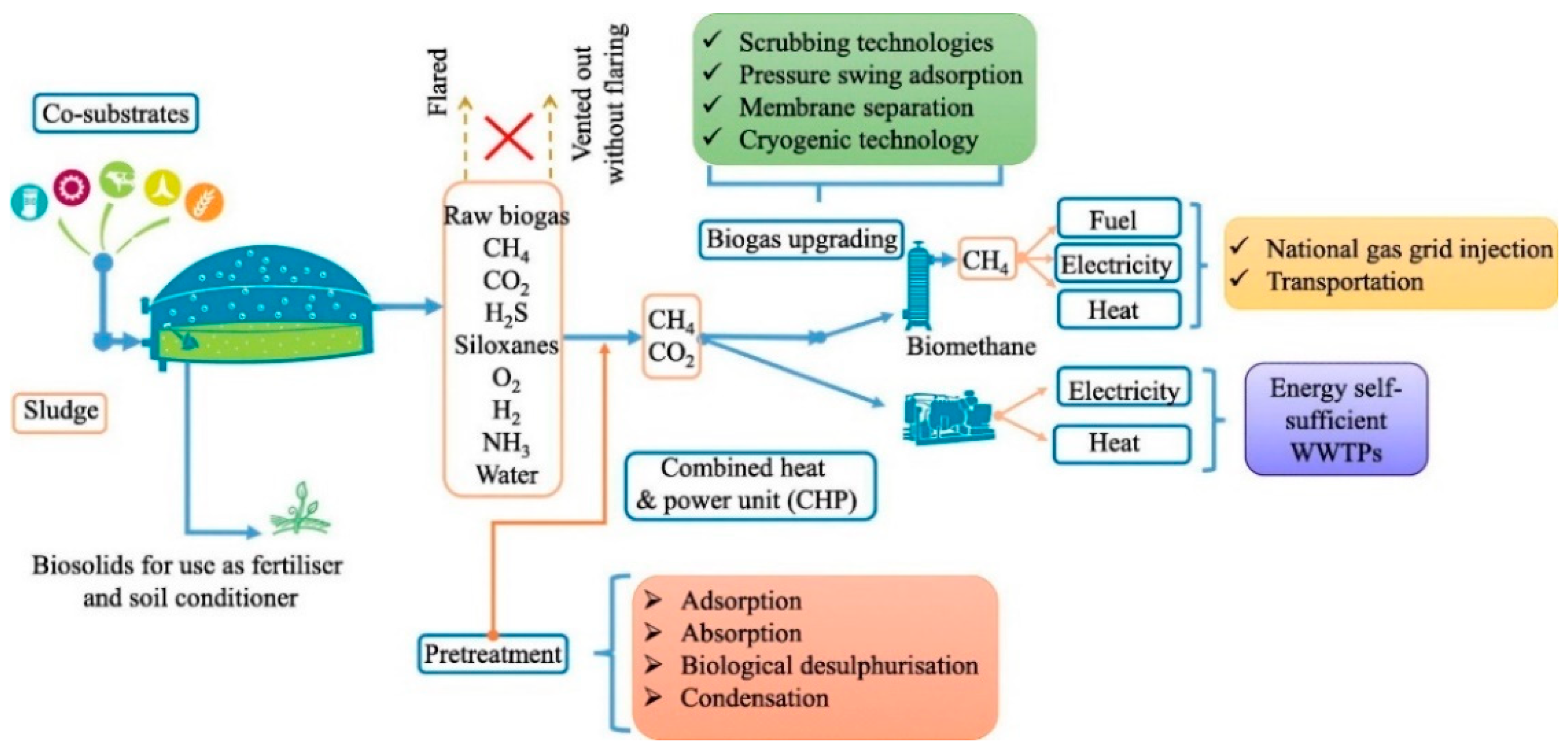
2. Biogas Production and Use

Biogas is produced via Anaerobic Digestion (AD) of organic substrates (e.g., fatty acids, proteins, and carbohydrates). Biomass sources include energy crops or, in a more circular economy-wise framework, waste biomass from other productive processes (e.g., animal manure, sewage sludge, agricultural wastes, food industry wastes) and waste biomass from the recycling system of municipal solid waste (OFMSW) [5,6,7,8,9,10,11]. The latter alternatives underline the potential of biogas for balancing the industrial costs of waste disposal, and it is mainly exploited to recover energy at the end-user side of the electricity transport and distribution network.
Typical end-users of this scenario are farms, having animal manure and/or agricultural wastes as biomass, wastewater treatment plants (WWTPs) that exploit sewage sludge, and food-related industries, such as whey/serum wastes of diaries [12].
The set of reactions that causes biogas production is named Anaerobic Digestion (AD), as it is carried out by anaerobic bacteria to sustain their metabolism. AD is divided into four main reactions: hydrolysis, acidogenesis, acetogenesis, and methanogenesis.
  • Hydrolysis allows complex molecules to be cracked into their monomers through water consumption. The reaction can be simplified as shown in Equation (1).
OH-[A1]-…-[An]-…[Am]-H + H2O → OH-…-[An]-H + OH-[An+1]-…[Am]-H,
The process is carried out until the original organic molecule is completely cracked into its monomers.
  • Acidogenesis. In this second phase, organic monomers are converted into other organic compounds such as organic acids and alcohol by the bacteria metabolism (fermentation). Carbon dioxide is also produced in this phase.
  • Acetogenesis. In this third phase, the acetogenic bacteria sustain their metabolism by consuming the acids and alcohols produced by the acidogenic population.
  • Methanogenesis. This last phase refers to the methane production as a metabolic leftover of methanogenic bacteria, which feed on the acetic acid produced in the previous step. Additionally, methane is also produced by CO2 reduction using elemental H2, which is a by-product of the previous reactions.
It is relevant to underline that these four phases occur contemporarily in the digester, allowing for a continuous feed of fresh biomass to sustain the hydrolytic bacteria and continuous production of biogas from the methanogenic ones. A full schematic of this set of reactions is reported in Figure 1 [13].
Alongside biogas, the result of the digestion process is a stabilized biomass (i.e., it does not undergo putrefaction) defined as ‘digestate’. Due to its stability and nutrient content, digestate can be further exploited for agricultural applications in a similar way to compost [14]. According to Möller & Müller [15] and Liedl et al. [16] digestate is a promising fertilizer for hydroponics. Finally, Panuccio et al. [17] analyzed solid and liquid fractions of digestate concluding that it can be exploited to grow high-quality fruit.
The AD process has been widely investigated for optimization purposes. Key parameters affecting AD are temperature, pH, C/N ratio, hydraulic retention time (HRT), and organic loading rate (OLR). These parameters can be optimized to reach a higher biogas yield. Mao et al. [18] analyzed the effect of the previously mentioned parameters to achieve a higher biogas production, claiming as follows.
  • Temperature optimum is reached if hydrolysis and acidogenesis occur under thermophilic conditions, whilst methanogenesis occurs under mesophilic conditions.
  • pH optimum is between 5.5 to 6.5 for acidogenesis and 7.0 for methanogenesis, thus, a two-stage AD to separate hydrolysis and acidogenesis to methanogenesis is preferred.
  • C/N ratio is optimized in a range of 25–30:1.
  • Hydraulic Retention Time and Organic Loading Rate optimization require a low OLR coupled with a long HRT to maximize the methane yield.

2.1. Biogas Utilization Paths

As previously stated, biogas applications range from heat production through direct combustion (e.g., boilers), to electricity or CHP production through ICE or HTFC, as well as its upgrade to biomethane. The upgrading process allows the methane content of biogas to be increased through CO2-removal, the resulting gas is biomethane and can be exploited for several green fuel applications, formerly associated with NG only, as liquefied biomethane production [19,20], injection in the NG grid (after the upgrading process) and vehicle fuel applications [21,22]. A basic scheme of the main steps for biogas production and use is provided in Figure 2.
Biogas can also be used as cooking gas (to fire stoves) which can provide positive health-related benefits in third world countries by substituting biomass which is currently the most common cooking fuel. Since biomass has a relatively poor combustion efficiency, its use lowers indoor air quality. Therefore, switching to biogas can boost the health-related sustainability of cooking fuel remaining within the RES framework [24].
However, biomass contains also chemical species different from carbon, hydrogen, and oxygen. Therefore, other compounds are generated along with CH4 and CO2 during the AD process. These compounds account for a limited percentage of the overall biogas (up to a few thousand ppmv) and thus are often referred to as “trace compounds”.
Typical trace compounds are inorganic sulfur compounds such as H2S, organic sulfur compounds, siloxanes, and organic sulfur compounds like DMS and CH4S, ammonia, and non-sulfur organic compounds (e.g., halogens).
These trace compounds often cause damage to end-uses technologies; therefore, raw biogas must be cleaned before use and the quality of the resulting gas must meet the technological constraints according to each application. Table 1 contains references to the H2S tolerance of main biogas-fed technologies.
This work aims at analyzing the main technologies for biogas deep cleaning. The following sections will contain detailed information about the main biogas contaminants and the most important cleaning technologies, which currently constitute the bottleneck of biogas applications.

2.2. Biogas Pollutants

In addition to methane and carbon dioxide, the biomass fed into the digester also determines the type and the abundance of its trace compounds. According to the literature review, the most abundant component in biogas is often hydrogen sulfide (H2S), which is harmful to many infrastructures and end-users. It originated from organic sulfur as a side effect of AD, and according to the biomass type, its concentration can reach several thousands of ppm(v). Despite being potentially the most abundant pollutant independently from the biomass source, its presence in raw biogas can be mitigated by precipitating sulfur directly inside the digester, for example using iron slats injections. For the same reason, WWTPs which perform treatments on the waterline using iron salts for phosphorus precipitation (to contain the eutrophication potential of the water) can obtain a sludge relatively poor in sulfur as well, resulting in an H2S abundance lower than 100 ppm(v) [28].
The second type of pollutant of significant concern for biogas applications is the set of silicon-containing molecules defined as siloxanes. Due to the use of silicon compounds in cosmetics and personal care products, siloxanes can become considerably abundant in biogas produced from sludge WWTP, with frequent fluctuations within the same day [28].
The following sections will provide a detailed analysis of the main biogas pollutants and their effect on the biogas end-uses technologies.

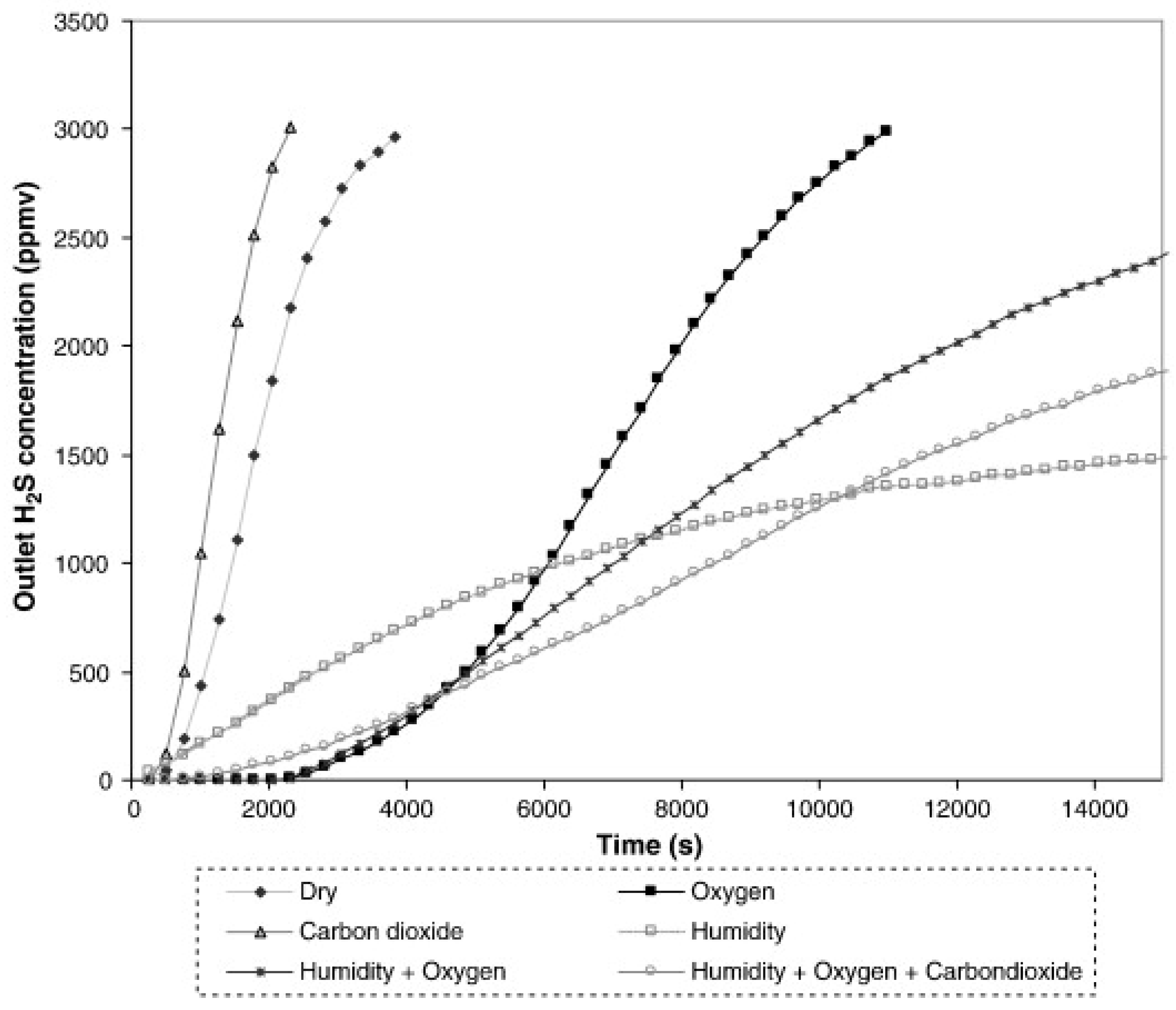
2.2.1. Hydrogen Sulfide

Hydrogen sulfide is a toxic and odorous gas, being a sulfur-containing compound makes it dangerous both for human health and for environmental quality. Its source in the digester is organic sulfur, which is degraded by methanogenic bacteria [32].
Its corrosivity causes damage to the pipes for gas transport and the internal combustion engines, whilst if biogas is electrochemically oxidized in a Solid Oxide Fuel Cell (SOFC) system, sulfur poisoning affects the anode side of the cells, deactivating the catalyst by converting the metal oxides into metal sulfides on the active surfaces. Furthermore, it interferes with the oxygen ions migration and reaction, leading to irreversible degradation of the stack’s performance [33].
If oxidated in bulk, for example in boilers or internal combustion engines, hydrogen sulfide becomes a source of sulfur oxides (SO2 and SO3, both known as SOx) which are evacuated along with the exhaust gas and thus enter the atmosphere. Sulfur oxides are among the main pollutants worsening air quality and pose consequences to human health and environmental protection.
Both SO2 and SO3 are toxic gasses, which affect the human breathing system, especially due to their irritative nature towards mucous membranes. In the atmosphere, the only relevant one is sulfur trioxide (or sulfuric anhydride), as sulfur dioxide is rapidly oxidized when mixed with air. Sulfuric anhydride is a precursor of acid rains, as it reacts with water to form sulfuric acid, causing harm to the environment and to several monuments and statues made of non-soluble carbonates, which are converted to soluble sulfides by the acid and washed out, leaving new layers exposed for further degradation [34,35].

2.2.2. Siloxanes

Siloxanes are organic, silicon-containing compounds with linear or cyclic structures. As they are often used in the production of shampoos, soaps, and cosmetics, and have a high-water solubility, they are present in the sludge of WWTPs [36]. If the sludge is used for biogas production, siloxanes volatilize possibly due to the increased temperature of the digester and enter the raw gas stream [37].
Their oxidation in ICEs causes deposits of solid silica on the heat exchanging surfaces, increasing the thermal resistance and decreasing the ICE performance. Additionally, siloxanes can both react with SOFC Ni-based catalyst and deposit solid silica on the anode surface, permanently decreasing the cell voltage [28,30,38].

2.2.3. Volatile Organic Compounds and Halogens

Volatile organic compounds (VOCs) in biogas include alcohols, alkanes, and aromatic and halogens compounds. They are present in different concentrations according to both the biomass type and the AD conditions. Halogenated hydrocarbons, for example, come from discarded refrigerants and plastic foams, therefore are more abundant in landfill gas, while some aromatic compounds (benzene, toluene, and xylene) are generated via decomposition processes, therefore their amount is affected both by age (decomposition processes) and the source of the waste [37].
Non-halogenated VOCs are currently not associated with HTFC poisoning, but their presence can affect the overall performance of adsorption-based siloxane removal stages. Conversely, halogenated compounds lead to corrosive products if oxidized, thus affecting pipeline and downstream equipment [39].
Finally, chlorine, phosphorus, and boron-containing halogens were proved able to damage SOFC in laboratory conditions. The damage was due to the reaction with the Ni-based catalyst on the anode side followed by the sublimation of the reaction product (NiCl2(g) for chlorine poisoning). However, the chlorine content of biogas is low enough to avoid the need for a dedicated cleaning stage [37,40,41,42,43,44].
A complete list of biogas trace compounds is contained in Table 2, this collection of data comes from the work of Papadias et al. [37] based on the data of the Argonne National Laboratory.

3. Biogas Cleaning and Upgrading Technologies

Biogas cleaning and upgrading technologies can be grouped according to three main working principles: adsorption, absorption, and cryogeny.
Adsorption-based systems work according to intermolecular interactions which bound pollutants on the active surface of a solid matrix. Materials of interest must be characterized by a high specific area and porosity to maximize solid-gas sites of interaction. As for absorption technologies, adsorption ones can also be enhanced through chemical interactions at the active sites which locally convert the pollutants to be removed in other species, which are easier to fix on the solid surface.
The absorption technologies working principle is related to the different solubility of gaseous compounds in specific solvents, which are used to scrub the gas flow to modify its composition and obtain higher methane content. As several organic solvents are degraded by sulfuric pollutants, physical absorption can be exploited as an upgrading technology only and require an already decontaminated gas.
Cryogenic technologies are a new field of research that exploits the different condensation temperature ranges of the different components in a biogas mixture to condense pollutants and freeze carbon dioxide, and easily remove them through gravity.

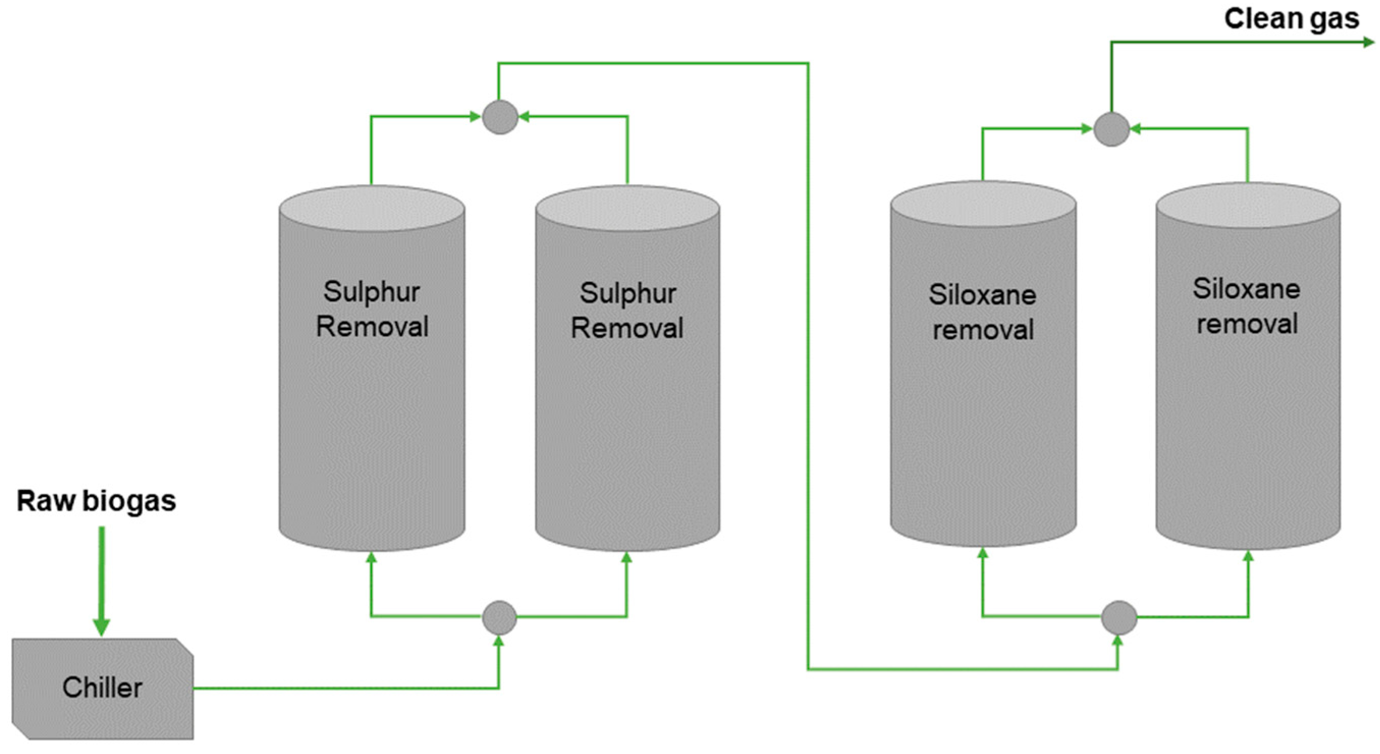
3.1. Adsorption-Based Systems

Adsorption phenomena occur when intermolecular bond formation draws gaseous species from the gas bulk to the surface of a solid. Interactions such as Van der Waals’s forces set the equilibrium between adsorbed molecules on the surface of the solid and the bulk concentration according to pressure and temperature.
The behavior of materials depends on three main parameters: the surface area, the pore size, and the pore distribution.
For the applications of interest, the most widely used materials are activated carbons (ACs), zeolite, and metal oxides, characterized by a saturation phenomenon, as the isothermal behavior shows a semi-horizontal plateau in the adsorption, which is associated with a linear behavior through the Langmuir Transformation, where the absolute pressure is related to the ratio of adsorbate quantity per absolute pressure.
Technologies based on adsorption aim at the optimization of the surface area to be exploited by forcing the gas flow through a solid matrix of adsorbent material in the form of a pellet or, in alternative cases, in powder. This process is dependent on Van der Waals forces but can be improved by an internal chemical reaction to convert the desired adsorbate into a chemical species which is easier to adsorb. Sitthikhankaew et al. [42] investigated the effect of O2 and humidity on ACs, their results showed a significant increase in ACs performance towards H2S adsorption, due to the deposition of elemental sulfur or the formation of sulfuric acid in the water film originated by humidity in the material’s pores.

3.1.1. Activated Carbons

Activated carbons (ACs) are a widely used technology for adsorption-based pollutants removal in different fields, among which biogas cleaning. They are produced when a high carbon-containing solid undergoes an activation process, leaving a solid residue rich in carbon contents, metals, and polycyclic aromatic hydrocarbons (PAHs, [43]). In adsorption-based systems, ACs are often in the form of powder (defined as powder-activated carbons, or PAC) or granular form (defined as granular activated carbons, GAC) [44], and can be impregnated with metals to increase the number of active sites.
ACs can be produced from fossil coal or solid pyrolysis wastes of biomass (e.g., wood [45], manure [46], food wastes [47]), although many authors tend to name biomass-based sorbents as pyrolytic chars or biochars [45].
The main characteristics of ACs are the surface area, porosity, and the presence of specific chemicals on the active sites of the surface. The latter characteristic distinguishes ACs into two main categories: impregnated AC and non-impregnated AC. Additionally, the possible activation processes of the material can also belong to one of two main groups: physical processes and chemical processes.
Physical activation occurs when the material is heated in an oxygen-deprived environment, for example through a flow of high-temperature steam. The aim is the carbonization of the material and the loss of its volatile fraction. Chemical activation occurs when the material is exposed to acid or alkaline baths (H2SO4, NaOH, KOH). This process causes, in addition to the material activation, its impregnation with inorganic species. As the impregnating chemicals can catalyze chemisorption reactions, commercially available impregnated ACs tend to be considered better performing than non-impregnated ones, especially if working with a biogas composition that can favor chemisorption (e.g., oxygen traces in the biogas stream). The downside of impregnated ACs is that it makes their waste management more complex from an environmental viewpoint [48].
Although chemical activation requires lower temperatures, and shorter activation times, in the frame of a circular economy, physical activation can play an important role as it allows the recovery of charcoal originated as a by-product of syngas in biomass gasification plants which is otherwise a waste to be disposed of by the plant owner [45].
The surface area, porosity, oxygen, and metal content of these chars made them interesting as a potential alternative to activated coal. Marchelli et al. [45] analyzed the behavior of different chars coming from biomass gasification plants in Sud Tyrol (Italy). The focus of their analysis was testing adsorption of H2S, and all biochars performed better than the ACs used as a positive control test, although, as underlined by the team itself, the chosen ACs might not be designed for H2S adsorption [45]. The adsorption capacity of the chars has been evaluated to vary from 1.61 mg g−1 for the worst performing one to 6.88 mg g−1 for the better performing one.
Chars BET area varied from 77.90 m2 g−1 to 586.72 m2 g−1, lower than those of the two different ACs used in positive control: 1002 m2 g−1 and 1269 m2 g−1 respectively. Parthasarathy et al. [49] analyzed the potential of bamboo for chars and ACs production, ACs were produced by treating chars with sulfuric acid, and the experiment results denote a significant increase of both ACs, and chars BET surface area if treating the bamboo particles (350–500 μm size) at high temperature, in this case, 1223 K. This led to 1106 m2 g−1 for ACs, and 350 m2 g−1 for chars.
Examples of impregnated ACs from different worldwide producers are listed in Table 3, sorbents are characterized in terms of specific surface area, a fundamental parameter for a solid matrix interacting with a gas stream (physisorption). The last column focuses on the key features of the sorbents or the family of sorbents from each supplier.

3.1.2. Metal Oxides

Metal oxides-based technologies exploit the properties of iron, zinc, and copper oxides for the chemisorption of hydrogen sulfide and siloxanes. The basic sulfur-removal mechanism is the conversion of the metal oxide to metal sulfide, as shown in Equation (2). The process is technically reversible, therefore metal oxides can be regenerated using an oxidizing stream leading to the formation of sulfur dioxide (SO2), which is removed by the stream itself, and elemental sulfur, if the oxidation is not complete. The presence of elemental sulfur on the surface has a detrimental effect on the material performance as it limits the number of regeneration cycles [57].
MexOy + yH2S → MexSy + yH2O,
The topic of regeneration will also be discussed in Section 3.1.5, where it will be underlined its relevance in the cost-benefits analysis of adsorption-based cleaning systems. An insight on zinc and copper oxide will follow, so as to underline some worth-mentioning aspects of the peculiar structural changes and void formation in zinc oxide and the downsides of copper oxides for DMS and DMDS-polluted streams, as is the case of biogas.

Zinc Oxides

Zinc oxide has been used for more than 30 years in the Oil & Gas industry to remove H2S from natural gas [30]. Therefore, it became a suitable option for biogas cleaning, showing the possibility to reach outlet concentrations below 1 ppm(v), starting with a pollutant concentration above 2000 ppm(v).
The guiding process is the sulfidation of the zinc oxide, as reported in Equation (3), which leads to the formation of zinc sulfide and water:
ZnO + H2S → ZnS + H2O,
This phenomenon can be often described using the shrinking core model (SCM) which considers the reaction front evolving from the surface of the ZnO grains into its core.
As water is a reaction product, the presence of humidity in the biogas stream can limit the reaction and even shift the equilibrium to the left side of the reaction, causing the re-oxidation of the spent sorbent and increasing the H2S content at the outlet of the bed. Additionally, CO2 can also limit the sorbent performances even if it is not directly involved in the reaction. It is suggested that the cause is the competitive adsorption of H2S and CO2 [58]. Grain outgrowth and void formation have been experimentally observed in ZnO used for desulfurization. Therefore, the shrinking core model is not suitable to match deeper degrees of approximation of the occurring phenomena [59]. These phenomena can be modeled by the hollow core-shell model (HCSM), which considers the reaction front to move outward thanks to the migration of ZnO from the core to the reactive surface. At larger scales, the observed outgrowth of the reaction front can cause pore-clogging and compromise the sorbent performances concerning those defined by experimental campaigns in the small, lab-scale, analysis [60].

Copper Oxides

Copper oxide-based sorbents are interesting for H2S capture, as they suffer no inhibitive effect on sulfur removal from CO2. Liu et al. [61] analyzed CuO-based sorbents for hydrogen sulfide removal from CO2 a stream, to study its potential for carbon recovery and sequestration. It was concluded that CuO-based sorbents can be a relevant option for low-temperature sulfur removal, but temperatures above 100 °C can lead to the formation of COS from the metal sulfide re-oxidation through CO2.
Additionally, “CuO oxide-based sorbents have been reported to potentially cause the formation of larger volatile sulfides from mercaptans in biogas” [30]. Calbry-Muzyka et al. [55] analyzed a two-bed cleaning unit using copper-related sorbents (activated carbons with copper in the active phase, and a copper-exchanged zeolite specifically), detecting a roll-up effect of DMS and DMDS which has been attributed to the presence of a copper oxide, which can, as well as other metal oxides, catalyze the formation of large thiols and sulfur organic compounds in the reactor, leading to the need of a second cleaning bed, dedicated to their removal.
Examples of metal oxide sorbents from different worldwide producers are reported in Table 4. The third column underlines the sorbents’ specific surface area, as we can see these values are considerably lower compared to the ones of ACs. This may depend on the fact that metal oxides perform desulfurization through chemisorption, not through physisorption.

3.1.3. Zeolites

Zeolites are aluminosilicates with the area, porosity, and composition which meet industrial criteria for several applications, such as water purification or catalytic cracking. Their crystalline structure allows zeolite to be implemented as adsorbents, different researchers worked on zeolites application for CO2 and N2 removal from natural gas, for deacidification purposes and energy content enhancement [66], and from flue gasses, for carbon capture and sequestration purposes [67]. In recent years, zeolites became more widely exploited as an adsorbent in the biogas industry for its decontamination from H2S and VOCs, as hydrophilic zeolites can be de-aluminized via chemical replacement of aluminum with silicon, becoming hydrophobic and able to bind nonpolar molecules as VOCs [30,68].
In the analysis of zeolite adsorption in the natural gas field, it has been observed that the presence of H2S and CO2 leads to the formation of carbonyl sulfide (COS), associated with the water affinity of the zeolite sorbent [69]. It is therefore important to evaluate this risk when working with biogas, especially if the adsorbent has an affinity towards water, to properly evaluate the performances of said sorbents in terms of hydrogen sulfide breakthrough, which is prolonged, and the roll-up effect, which would increase the sulfur content at the outlet of the reactor.

3.1.4. Adsorption-Based Systems Plant Layout

The basic design of an adsorption-based cleaning unit consists of a reactor bed, containing the sorbent material, and a piping system to supply the gas and remove the decontaminated stream. The key aspect of this design is the consumption of the sorbent, which must be periodically substituted when the outlet concentration reaches the breakthrough value, the value selected according to the technological limits considering a proper conservative safety margin (Table 1). Therefore, during periodical maintenance, this technology requires intermittent stops to remove the exhausted material and install a fresh bed.
The DEMOSOFC plant layout, shown in Figure 3, includes a double set of two beds each, both for sulfur and siloxane removal. Through the valves controlling the flow direction, the four beds are normally crossed by the total flow rate in a series configuration (lead and lag configuration). After the leading couple reaches the breakthrough, the two sets of reactors are operated in a parallel configuration, with the lagging couple working with the total flow rate whilst the leading couple is emptied and loaded with fresh sorbent. Finally, the series configuration is reached again, this time switching lead and lag concerning the initial case, so as to keep the fresh sorbent always on the end [7].
The goal of this design choice is to keep the plant potentially able to operate in continuity, even during sorbent-exchange operations. The choice of the sorbents has been made through an experimental campaign aiming for a complete characterization of the sorbents’ performances and, to optimize the result and minimize the cost, the chosen sorbents were the commercial ACs CKC and C64 for H2S and siloxanes respectively. This choice was made due to the presence of oxygen in the raw gas stream, which lead to the higher performances through chemisorption, a phenomenon that often occurs with impregnated ACs whilst not affecting other sorbents as metal oxides (in which chemisorption relies on the oxygen present in the sorbent, so not needing its presence in the biogas stream) [7].
The beds are characterized by a mass of 650 kg of AC for H2S removal and 1300 kg of AC for siloxane removal, leading to a breakthrough time (identified by continuous monitoring of the outlet biogas composition) of 6 months, leading to two sorbent changes per year [71].
A more complete list of commercial sorbents for biogas cleaning and their industrial price is reported in Table 5.

3.1.5. Benefits and Criticalities of Adsorption-Based Systems

Adsorption-based systems are a suitable choice for biogas cleaning if the target quality is high in terms of trace compounds removal, without the need to achieve an upgrading where also CO2 is removed (e.g., fuel cells applications) [73,74], since it is possible to load a reactor with different layers of sorbents (or have multiple reactors in series) for selective removal of different trace compounds. If the concentration of pollutants is elevated, the volume of materials becomes considerably high, leading to increased investment costs and difficulty in material loading/discharging operations. Conversely, if the volumes are kept limited, the sorbents’ replacement becomes more frequent with high operating costs. In this scenario, large biogas plants usually couple an adsorption-based cleaning unit with an upstream scrubber pre-treatment (either biological or chemical) to achieve a preliminary lowering in pollutant concentration (bulk sulfur removal).
Additionally, the proper use of sorbents may require a specific design of different cleaning stages in series to avoid roll-up effects. The proper sorbent selection depends also on the biogas composition, in terms of pollutants to be removed first and how their presence may interfere with the decontamination. Furthermore, humidity and oxygen proved to boost or reduce the adsorption capacity of several materials through chemisorption. These effects have been analyzed by several authors. For example, Figure 4 shows the different adsorption curves obtained from a reactor loaded with a KOH-impregnated AC working with different stream compositions. Sulfur would normally be removed through chemisorption employing the formation of potassium sulfide and potassium hydrogen sulfide but the presence of oxygen causes the deposition of solid sulfur both from H2S oxidation to water and due to the regeneration of the above-mentioned potassium sulfide species. Furthermore, at high H2S concentration, the presence of humidity can also play an important role in sulfur removal as H2S can partially dissolve in the water film that originates in the reactor bed [42].
The effect of oxygen traces on metals-containing sorbents is associated with the catalysis of the H2S oxidation to water and solid sulfur, as reported in Equations (4) and (5), and the lower part to sulfur dioxides, and is deactivated by direct sulfurization [75]:
Fe2O3 + 3H2S → Fe2S3 + 3H2O,
Fe2S3 + 3/2O2 → Fe2O + 3S0,
Moreover, oxygen regenerates iron oxides increasing the performance, and, on alkali and earth alkaline metals, it also regenerates the impregnating ions (as OH group in NaOH-impregnated AC, [76]), as reported in Equations (6) and (7):
H2S + OH → H2O + HS,
HS + 1/2O2 → S0 + OH,
Lastly, the presence of active groups in impregnated sorbents can provide the formation of chemical bonds as well, achieving performance enhancement due to chemisorption as well [77].
To summarize, the main key points of adsorption-based systems are:
  • ACs can effectively remove sulfur compounds and siloxanes, and in literature, ACs are often defined as the best performing materials in terms of adsorption.
  • AC regeneration is problematic. Therefore, industrial plants prefer to dispose of the exhausted ACs and substitute them with fresh ones [57].
  • Metal oxides are regenerated easily, but the presence of solid sulfur deposits limits the recovery of adsorption capacity.
  • High-quality commercial sorbents produced by the SulfaTrap company are metal oxides [64].
  • Zeolites are well-known at the commercial level for their use in natural gas cleaning applications and have therefore gained interest in biogas cleaning from H2S and VOCs.
  • COS formation from H2S and CO2 has been observed in zeolite cleaning reactors, leading to the risk of the roll-up effect.
The selection of the sorbents can significantly affect the cost of the cleaning system. Therefore, a proper understanding of the major criticalities of each sorbent type is crucial to highlight the most adequate solution.
When it comes to adsorption-based systems, waste management can play a significant role in the system cost. Hence, sorbets that can be regenerated offer a significant advantage compared to others. The possibility for regeneration highlights Metal Oxides over ACs. Some metal oxides can be disposed of directly into the digester once their total number of cycles is reached, significantly lowering the disposal cost of the sorbent [78]. Several suppliers offer sorbent reactivation and waste management services embedded in their contracts. Finally, national legislation can also play a significant role in the sorbent choice. Some countries may define an exhausted sorbent as ‘special waste’, thus requiring a designated waste-management chain. Conversely, other countries may allow for simpler disposal. A summary of the main aspects to compare ACs, MeOx and Zeolites are presented in Table 6.
As shown in Table 6, ACs often show poor regeneration potential. The reason is found in the high-temperature requirements and in the difficulty to maintain inert conditions at an industrial scale (i.e., regeneration in an N2 atmosphere). This results in the risk of auto-ignition of the AC due to atmospheric oxygen [57].
Metal oxides regeneration also occurs using high-temperature re-oxidation of metal to its oxide, and the oxidation of sulfur-to-sulfuric dioxide, which is desorbed from the solid surface and removed by the regeneration oxidizing stream [78]. Regeneration also causes a decrease in adsorption capacity, which can be related to the non-complete desulfurization and structural modifications during the previous adsorption process (HCSM for Zinc Oxide). According to the test conducted by Georgiadis et al. [57], ACs recovered 50% of the initial adsorption capacity from the first regeneration cycle, 25% from the second one, and stabilized to 15% from the sixth cycle on, while CuO sorbents maintained 75% of the initial adsorption capacity, whilst CuO-based sorbents with metal doping (Cu-Al-O and Fe-Cu-Al-O) showed a more limited recovery (50% and 43%, respectively).
The zeolite adsorption phenomenon is characterized by chemical reactions occurring due to the presence of water within the zeolite pores. Therefore, regeneration is limited by the formation of solid sulfur deposits within the sorbent matrix [79].

3.2. Scrubbers: Absorption-Based Systems and Biological Desulfurization

Absorption-based technologies exploit the solubility of different chemical compounds in a liquid solvent such as water, organic solvents, or chemical reactants. The main goal of this type of technology can be biogas upgrading to biomethane if the solvent is designed for CO2 removal or desulfurization. This distinction depends on the technical constraints characterizing the solvent tolerance to sulfur and the cost optimization associated with the solvent regeneration energy demand.
Additionally, according to the system optimization, related to the plant size, it is possible to have scrubbers operating as a pre-treatment stage before an adsorption column. This strategy aims at a preliminary H2S concentration lowering before the adsorption cleaning to avoid the need for large sorbent volumes, which may be potentially complex to deal with and not particularly cost-effective.

3.2.1. Water Scrubbing

Water scrubbing is the most widely exploited technique for biogas upgrading, it is the simplest of the three options and it has a relatively low capital cost [23]. Due to the corrosivity of hydrogen sulfide in water, it requires working with a pre-treated, decontaminated, gas [80]. Pre-treatment also pressurizes the gas to improve solubility: at 6 to 10 bar and 40 °C, CO2 solubility is assessed to be 26 times higher than the one of CH4 [23,81]. Biomethane purity can reach 80% to 99%, according to the non-condensable gasses content [80].
As shown in Figure 5, pre-treated biogas meets water in counter-current, and carbon dioxide (mainly) and methane are dissolved in the liquid and collected from the bottom of the reactor, whilst biomethane is extracted from the top. The CO2—enriched solution is flashed to favor desorption, to recover part of the methane by recirculating the gas to the inlet.
Water is later regenerated in a counter-current flow with air to strip the solution from the remaining carbon dioxide, the resulting exhaust gas is vented to a flame, to properly oxidize its methane content before its discharge into the environment. It is possible to co-remove carbon dioxide and hydrogen sulfide, in case the sulfur content in the input biogas is high, hydrogen sulfide oxidation may lead to solid sulfur deposition, as shown in Equation (8):
2H2S + O2 → 2S + 2H2O,
In this case, it is preferred to regenerate water using an inert gas, such as N2, this solution also solves the issue of oxygen contamination of biomethane, which is a potential consequence of air stripping that can compromise significantly the resulting biomethane quality and utilization [82].
The main pros of water scrubbing are its operational simplicity and its low energy consumption, while its major drawbacks are high water consumption if no regeneration is implemented and its methane losses [23]. A dehumidification unit is also needed downstream, to remove water from the upgraded gas, as the water used for the scrubbing process can saturate the gas mixture [21]. It is relevant to point out that, water “single-use” (i.e., no regeneration process is implemented) can be potentially an economic-wise design when biogas is obtained in WWTPs, as the main plant already provides clean water to be discharged into the environment or exploited for other industrial uses if any. This way, the potential risk of contamination by elementary sulfur is avoided too [21,22,81,82].

3.2.2. Scrubbing with Organic Solvents

Organic solvents working principle is the same as water scrubbing, using organic solvents like methanol and dimethyl ethers of polyethylene glycol mixtures, exploited for CO2 capture and, potentially, H2S co-capture as well [81]. The working principle of organic solvent scrubbing is the same as water scrubbing (i.e., physisorption exploiting gasses solubility), but the solubility of carbon dioxide is consistently higher if compared to water. This leads to the main advantages concerning water scrubbing: lower flow demand and smaller sizes of the cleaning unit, but also to higher difficulties in regeneration which, if working with organic fluids, cannot be avoided.
The downsides of this technology are relatively similar to those of water scrubbing: oxygen and nitrogen cannot be removed, and methane losses can be significant [37]. Additionally, even though organic solvents can effectively absorb hydrogen sulfide, their high solubility makes regeneration difficult, needing a higher stripper working temperature [81]. To avoid these issues, hydrogen sulfide is often removed before the scrubbing, making organic solvents a technology of interest only for upgrading purposes rather than other biogas utilization as SOFC fuel.
Typical working conditions are 7–8 bars and 20 °C for scrubbing, and 1 bar and 80 °C for stripping. Additionally, to the organic fluid cooling needs for regeneration and reuse, biogas must also be cooled after its compression to maximize CO2 solubility, so the biomethane CH4 content, can reach 98% [81,83].

3.2.3. Chemical Scrubbing

Chemical absorption processes work with a dynamic that is similar to one of the other scrubbing-based methods but allows chemical reactions to occur to enhance pollutants removal from the gas stream.
Scrubbing, when oriented to upgrading processes, is performed using amine-based solutions (as MEA or DMEA) which are selective towards acid gasses such as CO2 and H2S. This makes scrubbing with amines able to perform desulfurization and upgrading at the same time, but the reaction with sulfur is irreversible, which makes this strategy unfeasible due to the need to regenerate the spent liquid at reasonable energy and economic prices. Therefore, this type of chemical scrubbing must be coupled with an upstream desulfurization technology to produce high-quality biomethane (99%vol.) [23]. The H2S tolerance of chemical scrubbers is assessed to be below 6 ppm(v), furthermore, to avoid unwanted chemical reactions, it is also needed to work in low oxygen conditions [26]. This technology also poses the need to optimize the operating temperature due to the competition between absorption into the liquid phase (favored at low temperatures) and the chemical reactions within the liquid phase (favored at high temperatures) [84]. Typical working temperatures are in the range of 120–160 °C [26] making this solution relatively convenient in case cheap heat is available [85].
The working principle of a chemical scrubber system is exploiting the exothermic absorption of carbon dioxide in an absorber column, where the biogas stream flows through a packed bed to meet a counterflow of amine solution. The packed bed maximizes the contact area and clean biogas leaves the column from the top side. The liquid solution is collected from the bottom side of the column and immediately regenerated, allowing the system to work continuously. Regeneration of the sorbent occurs in a stripper column in which a boiler provides the desorption heat needed to extract CO2 from the solution. The gas stream is extracted and sent to disposal without the need for post-combustion as the high selectivity of amine solutions limits the amount of methane in the waste gas stream [23]. The liquid flow is collected on the bottom side of the stripper column and sent back to the absorber one. A proper simple heat exchanger design is needed for the internal heat recovery between the two columns to limit the energy consumption of the boiler.
The possibility to perform chemical removal of H2S has been analyzed by Couvert et al. [86] and Cano et al. [87] using oxidizing species such as H2O2, NaOH, HClO, and the OH group provided by the alkaline species. The oxidation reactions lead to the production of elemental sulfur and sulfite groups as SO32− and SO42−.
Since the goal of the study conducted by Cano et al. [87] was the analysis of the environmental impact of different desulfurization technologies through LCA, it is important to point out that chemical scrubbing, along with adsorption on ACs, was characterized by considerably high emissions (30 and 40 kg CO2eq per kg S in H2S respectively). Conversely, biological desulfurization was highlighted as better performing, with only 13.9–18.7 kg CO2eq per kg S in H2S, depending on the process being aerobic or anoxic.

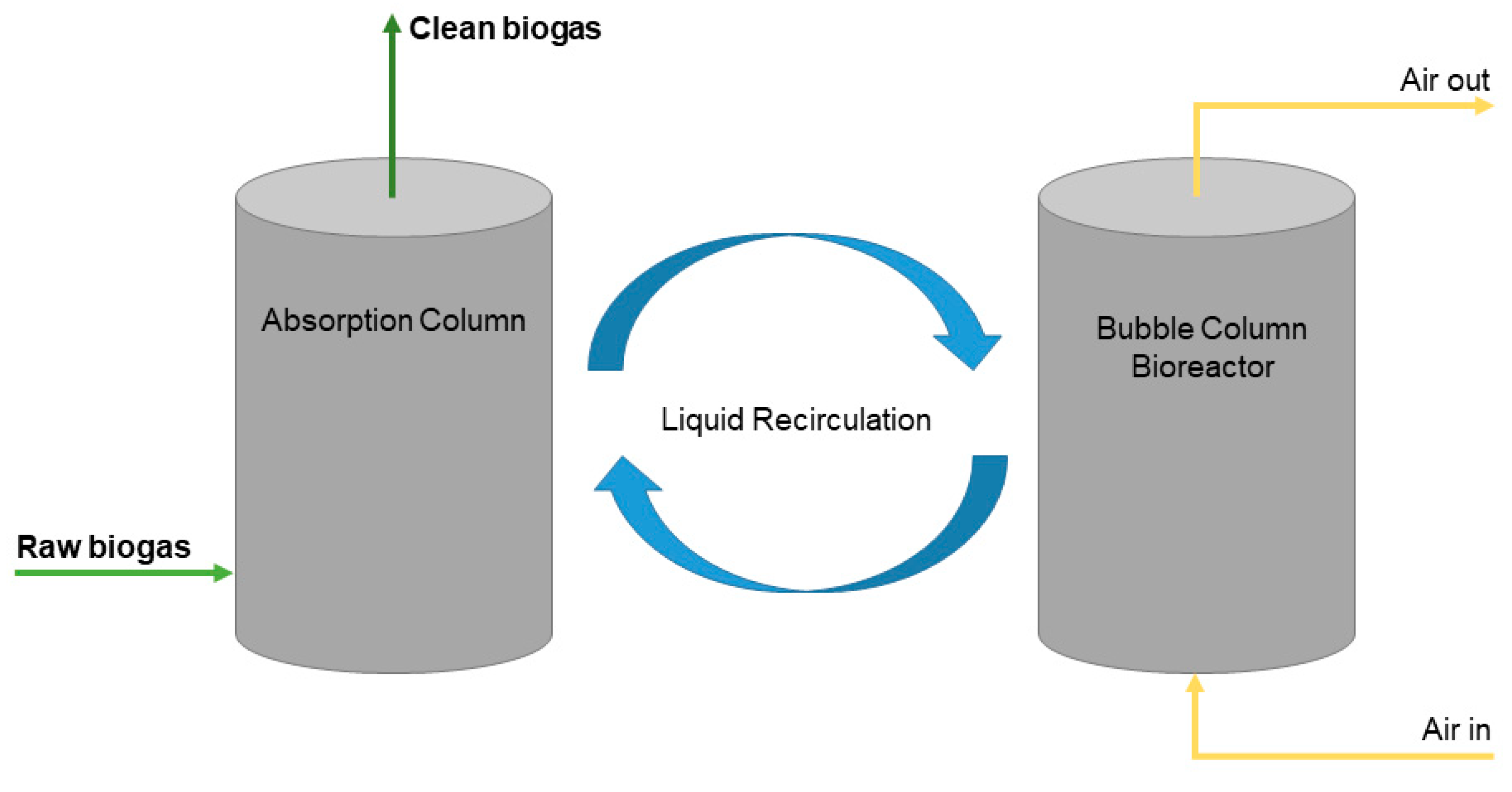
3.2.4. Biological Scrubbing and Filtering

Biological scrubbers implement the same design of the absorption-based systems, but instead of removing sulfur dissolving into a liquid medium, and eventually reacting with the chemical present there, biological scrubbers consume sulfur through the metabolic activity of specific bacteria populations.
Biotrickling filters are packed bed reactors using microbial films on the inner surfaces for microbial growth. The H2S can be oxidized to elemental sulfur and sulfate using elemental oxygen. This strategy requires the use of stoichiometric oxygen and exposes the plant to potential risks related to the formation of an explosive mixture if the O2 level reaches the flammability limits (5–15%) [88].
An alternative can be the anoxic H2S elimination using nitrate as oxidizing source, reported in Equation (9):
15NO3 + 12H2S → 9H2O + 6S0 + 6SO42− + 5 N2 + 2OH + 4H+,
Fernández et al. [89] investigated the H2S anoxic elimination through dissimilatory nitrate reduction (as described by Equation (9)) in a bio trickling filter packed with polypropylene Pall rings, obtaining a removal efficiency of 99% of sulfur. This solution avoids the lowering of methane concentration and reaching desulfurization standards compatible with NG grid injection. Additionally, the use of Pall rings diminishes pressure drops, thus limiting elemental sulfur (and biomass from the inoculum) deposits and the related risk of clogging.
The main positive aspect of this technology is to achieve a desulfurization efficiency comparable with other desulfurization technologies (adsorption systems and chemical scrubbing) without the issue of waste materials to dispose of or regenerate with high energy consumption [87].
Elemental sulfur deposition occurs when the biogas is rich in H2S, as its complete oxidation to SO4 is tougher to obtain. A possible solution would be to work with an excess of oxygen, to ensure sulfur complete oxidation, but the resulting oxygen excess leads to the dilution of methane, depleting biogas quality. For this reason, San-Valero et al. [90] analyzed the possibility reach biogas desulfurization using a completely aerobic reactor, obtained by combining an absorption column with a bubbler column. The results showed a removal efficiency assessed around 80%, without the issues of elemental sulfur deposition and biogas dilution, concluding that this technology is potentially feasible for industrial applications.
The reactor scheme is shown in Figure 6. In the absorption column biogas is scrubbed by the liquid in counter-flow, resulting in H2S absorption. The liquid is recirculated to the bubbler column where it meets oxygen from the air stream. In the bubbler column, the pH measure regulated the feeding of NaHCO3, which is the inorganic carbon source for sulfur-oxidizing microorganisms’ growth.

3.2.5. Absorption-Based Systems Comparison

In the frame of biogas desulfurization, both water scrubbing and biological scrubbing can play an important role, depending on the desulfurization requirements. Chemical scrubbing using oxidizing species is a possible strategy as well, although it is less environmentally sustainable than the others.
If the sulfur content of raw biogas is considerably high, and deep desulfurization requirements must be met, it is possible to couple the adsorption bed with an upstream scrubber. This strategy allows a preliminary reduction of the sulfur content, thus limiting the inlet concentration in the adsorption bed and therefore the bed size and number of sorbent exchanges per year. This solution is practiced in large plants, where techno-economic optimization allows this type of layout.
The key features of each scrubber technology are listed in Table 7. Water scrubbing can be a convenient solution in WWTPs by recovering freshwater from the plant itself. Otherwise, water regeneration is needed to avoid excessive water consumption. Physical and Chemical scrubbing use optimized solvents, thus the material quantities are limited and there is no need for a flash column since the high selectivity of amines considerably limits methane losses. Regeneration is mandatory to recover the solvent (physical scrubbing) or the reactants (chemical scrubbing); therefore, these scrubbers can be an optimized option if there is an availability of heat to recover. These scrubbers are often used to upgrade already sulfur-free biogas.
Biogas cleaning occurs through biological scrubbing and chemical scrubbing (if oxidizing species are used as reactants). Between these two options, biological scrubbers can be considered a more convenient option since it does not require pressurization and regeneration heating to work.

3.2.6. Absorption-Based Systems Plant Layout Analysis

The basic design of an absorption-based cleaning unit, shown in Figure 7, consists of a scrubber column coupled with a regeneration column. The biogas stream and the solvent stream cross the scrubber in counterflow, to maximize the contact area and, consequentially, the mass transfer. The flash column, shown in the picture, allows partial recovery of methane, limiting the losses [23]. Plants where scrubbing occurs using an organic solvent, and plants performing chemical scrubbing, also require a heat duty to sustain the regeneration process. Therefore, heating and exhaust gas discharging loops are connected to the regeneration column.
Specific plants, like water scrubbing plants located in WWTPs, may have a simpler design, as in those cases no regeneration is required since it is possible to exploit the continuous clean water production of the WWTP.
Biological scrubbers often perform absorption in the same column where biological oxidation occurs, therefore their layout has often one column. For these plants, the main issues are related to the risks of clogging, due to solid sulfur and biomass deposits, and the dilution of methane due to oxygen. The same problem is also present in water scrubbing plants if the regeneration column is stripped with air.

3.3. Cryogenic Technology

Cryogenic technologies are an innovative set of techniques based on the different temperatures of condensation of the different components of the raw biogas streams.
The goal of cryogenic separation is to decontaminate and/or upgrade biogas through a distillation of a two-phase stream. Since this technology allows the production of high-purity and, with little extra energy consumption, liquid biomethane, its application for a SOFC-system cleaning unit may not be the optimal choice, since SOFC systems can withstand the carbon dioxide content of biogas. Nonetheless, it can be an interesting choice for energy and chemicals recovery from biowastes, as its main positive aspect is the cogeneration of both biomethane and carbon dioxide.
The latter can be recovered as snow or dry ice, with snow being the preferred way for its precipitation since direct dry ice formation causes an increase in thermal resistance and therefore a progressive loss of efficiency [91]. After being recovered, CO2 be used in several industrial applications (e.g., dry ice production).
Biomethane can also be cooled further to produce liquid biomethane, and consequentially, to exploit well-known LNG technologies for its distribution and use [92]. According to Hofmann et al. [19], the first components to be eliminated are H2S, H2O, and NH3, which can be removed from biogas in a significant amount above cryogenic temperatures. The cryogenic separation unit they analyzed is claimed to be able to produce liquid biomethane at 111 K.

3.3.1. Cryogenic Plant Design Analysis

Cryogenic systems exploit distillation; therefore, the core aspects of its design are a cryogenic system able to produce the cooling needs to refrigerate the biogas stream, and a set of distillation columns able to separate the vapor phase (enriched in methane) from the condensed phase (enriched in carbon dioxide). A plant layout is shown in Figure 7.
In the framework of the Waste2Watts EU project [93], a cryogenic cleaning system aimed at removing sulfur and silicon compounds in large biogas plants are under development. The system will have a cooling power production section (which could be based on a reverse Stirling engine, adsorption chiller, or a nitrogen open loop). The as-produced cooling power is then used to cool down the biogas and remove harmful contaminants up to very low levels. When only cleaning is performed (and not upgrading) the main risk is the CO2 freezing (which is indeed searched in upgrading cryogenic units) which would turn the purification to be ineffective. From the modeling of the cryogenic phenomenon with a CH4-CO2 mixture [94], it has been pointed out that siloxanes condensing temperatures are relatively high and these contaminants are removed easily by reaching −40/−60 °C. Hydrogen sulfide is indeed removed (depending on its share in the biogas stream) at a temperature that is close to or even lower than −100 °C, close to the CO2 freezing point. The innovative cryogenic biogas cleaning prototype is under construction and will be tested in a real biogas plant at the end of 2022. If results will be positive, cryogenic could be a more efficient and environmentally friendly solution for large biogas plants, which would run only on electricity without the need for sorbents or chemicals.
Figure 7. Cryogenic distillation plant scheme. The flows are listed as S followed by a number, the * has been used to highlight the two flows characterized by high CO2 content (above 99%vol.). Reproduced with permission from [95]; published by Elsevier, 2018.
Energies 15 03551 g007

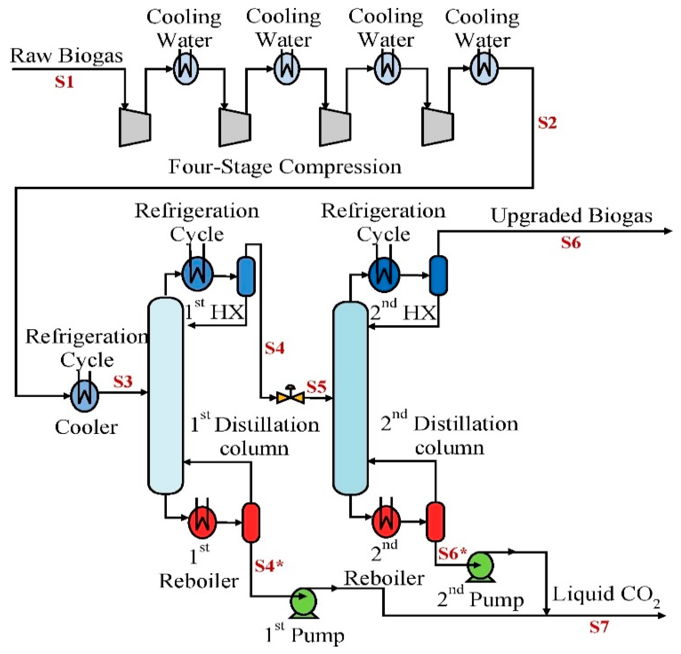
3.3.2. Carbon Dioxide Freeze-Out

The main issue with carbon dioxide is its freeze-out on the distillation trays. Solid carbon dioxide is an obstacle to the long-term operation of the plant and generates thermal resistance when deposited over the surface of the heat exchangers. This can be avoided if the solid carbon dioxide is de-sublimated as snow, whose lack of adherence cause it to not deposit on the surfaces and to be deposited on the bottom of the heat exchangers where it is removed as dry ice at regular intervals [91].
This strategy forces intermittencies in the use of the plant and requires removing carbon dioxide as a solid. As an alternative, it is possible to work above de-sublimation temperature by setting the key parameters like pressure and composition. Carbon dioxide is collected from the bottom of the distillation column, allowing its removal in continuous operation.

3.3.3. Comparing Innovative Cryogenic Systems to Other Upgrading Technologies

In terms of methane purity, cryogenic separation allows reaching a similar range to one of the absorption-based technologies, which makes it suitable for grid injection purposes. Conversely, methane losses are extremely low compared to other systems. Yousef et al. [95] claimed that, according to their simulation results, the two-column system under study could reach methane losses of approximately 0.05%, which makes this type of technology “more competitive among the other upgrading techniques”.
The main pros of this technology are:
  • Biomethane with high methane purity.
  • Extremely low methane losses.
  • High purity carbon dioxide recovery.
  • No chemical reactions, no reactants purchasing cost.
  • No continuous hazardous waste production (e.g., impregnated ACs).
The main cons of this technology are:
  • Not mature technology, still under development.
  • High CAPEX and OPEX due to the high energy consumption.
  • Occasional need to use fresh coolant (infrequent hazardous waste production) [92].
A summary of the biomethane quality (CH4 content) is reported in Table 8, comparing cryogenic separation with other upgrading technologies on the market. The complementary information on methane losses is also reported in Table 9.
Although cryogenic separation appears as the technology characterized by lower losses, it is important to account that it is a relatively young technology, whilst the others in the tables are well known and established on the market.

4. Technology Comparison and Discussion

The emerging benefits and criticalities of each of the previously analyzed technologies are listed in Table 10. Quality targets that can be reached by these technologies, along with their major drawbacks, can be used to define a set of guidelines to better understand which type of plant can meet the standards of specific biogas uses. For example, SOFC applications require a thorough removal of both sulfur and siloxanes. This quality can be achieved using adsorption-based systems. Conversely, among the scrubbing technologies, biological scrubbers are an efficient way to achieve desulfurization, thus they can be implemented for non-SOFC applications as biogas upgrading (before a second scrubber for CO2 removal). Biological or chemical scrubbers can also be exploited for SOFC applications if coupled with an adsorption-based system. Here, the scrubber is used to diminish the sulfur content, thus limiting the solid sorbent quantity needed.
Other absorption-based systems applications are mainly limited to biogas upgrading. Water scrubbing is often associated with higher methane losses but can become economically favored in WWTPs when freshwater is recovered from the plant itself. Physical and chemical scrubbers limit significantly methane losses, thus the quantity of needed solvent, but requires operating pressurized amine solutions (physical) or reactants (chemical) at high temperature (for the regeneration process). Cryogenic separation is a relatively new concept; thus, it is not affirmed on the market. This technology can be exploited for biogas purification and upgrading; moreover, if the temperature is further reduced liquid biomethane (LBM) can be obtained. One key criticality is CO2 freezing, which can cause solid deposits that affect the operability of the system. Nevertheless, if CO2 is deposited as snow, it is possible to easily remove it, thus recovering high-purity dry ice for other applications.

5. Conclusions

The following work reviews commercially available technologies along with new concepts, like cryogenic separation. Biogas purification requirements depend on the intended final application (cogeneration internal combustion engines, fuel cells, grid injection).
Adsorption-based systems, exploiting impregnated ACs and metal oxides, can achieve sulfur-free biogas and remove siloxanes. Therefore, this type of solution has been often exploited in biogas-fed SOFC applications.
Scrubbers can take part in biogas cleaning and upgrading processes: water scrubbing can diminish H2S concentration in biogas to a few hundreds of ppm(v), but they are not designed for organic sulfur removal and may cause solid sulfur deposition to occur. Scrubbers with organic solvents are often unexploitable for desulfurization due to the high regeneration energy that would be necessary to desorb sulfur. Therefore, this type of technology is almost exclusively dedicated to upgrading processes. Typical chemical scrubbers working with amine cannot be used for desulfurization due to the irreversibility of the reaction with sulfur, which would have a detrimental effect on the scrubbing solution. Conversely, it is possible to achieve good desulfurization standards if working with oxidizing reactants like H2O2, NaOH, HClO, and the OH group provided by the alkaline species. Nevertheless, this solution is often perceived as not sustainable, as opposed to biological scrubbers and filters, which perform desulfurization via sulfur-digesting bacteria.
Biological desulfurization can be achieved via oxidizing and anoxic reactions. The latter employs nitrate as the oxidizing source, thus avoiding the risk of an explosion which must be considered in the first case, due to the use of oxygen for the bacteria’s metabolic activity.
Finally, cryogenic distillation can provide an interesting alternative for large-size plants, achieving high purity standards, recovering carbon dioxide as dry ice as a by-product, and potentially achieving LBM production.
Considering that scrubbers are a well-known technology, most future research efforts are expected to be on adsorption-based systems. Several pieces of research are being focused on ACs production from recovered biomass. Regeneration is also a crucial aspect of waste minimization. In this field, thermal and chemical regeneration treatments can achieve different levels of desorption opposing the high energy needs to the implicit risk of operations with hazardous chemicals. Moreover, the most efficient and environmentally friendly way to generate power from biogas is through HTFCs. This solution needs a deep and complete removal of the biogas contaminants, unachievable with traditional scrubbers. Cryogenic distillation can achieve very competitive desulfurization goals, but it is relatively new on the market; thus, it is feasible to be implemented only in large size financed plants. It is possible to conclude that achieving a higher energy generation from biogas production will highlight the relevance of adsorption-based cleaning systems. Research activities focused on biogas cleaning Life Cycle Assessment, sorbents regeneration and sorbents waste disposal are expected to grow over the next years.

Author Contributions

Conceptualization, M.G. and R.P.; methodology, R.P.; investigation, R.P.; writing—original draft preparation, R.P.; writing—review and editing, R.P., M.G. and A.L.; visualization, M.G.; supervision, M.G. and A.L. All authors have read and agreed to the published version of the manuscript.

Funding

This research received no external funding.

Institutional Review Board Statement

Not applicable.

Informed Consent Statement

Not applicable.

Data Availability Statement

Not applicable.

Acknowledgments

The authors would like to thank Sonia Fiorilli and Mattia Pagani from the Department of Applied Science and Technology, Politecnico di Torino for their work on sorbets characterization.

Conflicts of Interest

The authors declare no conflict of interest.

References

  1. European Green Deal. Available online: https://ec.europa.eu/clima/eu-action/european-green-deal_en (accessed on 27 April 2022).
  2. EU Climate Action and the European Green Deal|Climate Action. Available online: https://ec.europa.eu/clima/policies/eu-climate-action (accessed on 5 June 2021).
  3. Tian, W.; Li, J.; Zhu, L.; Li, W.; He, L.; Gu, L.; Deng, R.; Shi, D.; Chai, H.; Gao, M. Insights of Enhancing Methane Production under High-Solid Anaerobic Digestion of Wheat Straw by Calcium Peroxide Pretreatment and Zero Valent Iron Addition. Renew. Energy 2021, 177, 1321–1332. [Google Scholar] [CrossRef]
  4. Sarker, S.; Lamb, J.J.; Hjelme, D.R.; Lien, K.M. Overview of Recent Progress towards In-Situ Biogas Upgradation Techniques. Fuel 2018, 226, 686–697. [Google Scholar] [CrossRef]
  5. Nilsson, M.; Zamparutti, T.; Petersen, J.E.; Nykvist, B.; Rudberg, P.; Mcguinn, J. Understanding Policy Coherence: Analytical Framework and Examples of Sector-Environment Policy Interactions in the EU. Environ. Policy Gov. 2012, 22, 395–423. [Google Scholar] [CrossRef]
  6. Riley, D.M.; Tian, J.; Güngör-Demirci, G.; Phelan, P.; Villalobos, J.R.; Milcarek, R.J. Techno-Economic Assessment of CHP Systems in Wastewater Treatment Plants. Environments 2020, 7, 74. [Google Scholar] [CrossRef]
  7. Gandiglio, M.; Lanzini, A.; Santarelli, M.; Acri, M.; Hakala, T.; Rautanen, M. Results from an Industrial Size Biogas-Fed SOFC Plant (the DEMOSOFC Project). Int. J. Hydrogen Energy 2020, 45, 5449–5464. [Google Scholar] [CrossRef]
  8. DEMOnstration of Large SOFC System Fed with Biogas from WWTP|DEMOSOFC Project|H2020|CORDIS|European Commission. Available online: https://cordis.europa.eu/project/id/671470 (accessed on 5 June 2021).
  9. Deliverable “DEMOnstration of Large SOFC System Fed with Biogas from WWTP”. Available online: http://www.demosofc.eu/wp-content/uploads/2017/10/SOFC-based-CHP-market-potential-analysis.pdf (accessed on 5 June 2021).
  10. DESCRIPTION|Waste2watts-Project. Available online: https://waste2watts-project.net/description/ (accessed on 5 June 2021).
  11. Appels, L.; Baeyens, J.; Degrève, J.; Dewil, R. Principles and Potential of the Anaerobic Digestion of Waste-Activated Sludge. Prog. Energy Combust. Sci. 2008, 34, 755–781. [Google Scholar] [CrossRef]
  12. EUR-Lex-32019R1009-EN-EUR-Lex. Available online: https://eur-lex.europa.eu/legal-content/EN/TXT/?uri=CELEX%3A32019R1009 (accessed on 4 June 2021).
  13. Dahiya, S.; Kumar, A.N.; Shanthi Sravan, J.; Chatterjee, S.; Sarkar, O.; Mohan, S.V. Food Waste Biorefinery: Sustainable Strategy for Circular Bioeconomy; Elsevier Ltd.: Amsterdam, The Netherlands, 2018; Volume 248. [Google Scholar]
  14. Lisowyj, M.; Wright, M.M. A Review of Biogas and an Assessment of Its Economic Impact and Future Role as a Renewable Energy Source. Rev. Chem. Eng. 2020, 36, 401–421. [Google Scholar] [CrossRef]
  15. Möller, K.; Müller, T. Effects of Anaerobic Digestion on Digestate Nutrient Availability and Crop Growth: A Review Anaerobic Digestion (AD) for Biogas Production Leads to Several Changes in The. Eng. Life Sci. 2012, 12, 242–257. [Google Scholar] [CrossRef]
  16. Liedl, B.E.; Cummins, M.; Young, A.; Williams, M.L.; Chatfield, J.M. Hydroponic Lettuce Production Using Liquid Effluent from Poultry Waste Bioremediation as a Nutrient Source. In Proceedings of the VII International Symposium on Protected Cultivation in Mild Winter Climates: Production, Pest Management and Global Competition, Recife, Brazil, 1 January 2004; Volume 659. [Google Scholar]
  17. Panuccio, M.R.; Mallamaci, C.; Attinà, E.; Muscolo, A. Using Digestate as Fertilizer for a Sustainable Tomato Cultivation. Sustainability 2021, 13, 1574. [Google Scholar] [CrossRef]
  18. Mao, C.; Feng, Y.; Wang, X.; Ren, G. Review on Research Achievements of Biogas from Anaerobic Digestion. Renew. Sustain. Energy Rev. 2015, 45, 540–555. [Google Scholar] [CrossRef]
  19. Hofmann, J.; Nachtmann, K.; Falk, O.; Baum, S.; Fuchsz, M. Pressureless Cryogenic Conversion of Biogas into Liquefied Biomethane and Solid Carbon Dioxide. In Proceedings of the European Biomass Conference and Exhibition Proceedings, Amsterdam, The Netherlands, 6–9 June 2016; Volume 2016. [Google Scholar]
  20. Nachtmann, K.; Baum, S.; Fuchsz, M.; Falk, O.; Hofmann, J. Efficient Storage and Mobile Use of Biogas as Liquid Biomethane. Landtechnik 2017, 72, 179–201. [Google Scholar] [CrossRef]
  21. Persson, M.; Jonsson, O.; Wellinger, A. Biogas Upgrading to Vehicle Fuel Standards and Grid. IEA Bioenergy 2007, 37, 1–32. [Google Scholar]
  22. Wellinger, A.; Lindberg, A. Biogas Upgrading and Utilisation. IEA Bioenergy 2000, 24, 3–20. [Google Scholar]
  23. Nguyen, L.N.; Kumar, J.; Vu, M.T.; Mohammed, J.A.H.; Pathak, N.; Commault, A.S.; Sutherland, D.; Zdarta, J.; Tyagi, V.K.; Nghiem, L.D. Biomethane Production from Anaerobic Co-Digestion at Wastewater Treatment Plants: A Critical Review on Development and Innovations in Biogas Upgrading Techniques. Sci. Total Environ. 2021, 765, 142753. [Google Scholar] [CrossRef] [PubMed]
  24. Bruce, N.; Pope, D.; Rehfuess, E.; Balakrishnan, K.; Adair-Rohani, H.; Dora, C. WHO Indoor Air Quality Guidelines on Household Fuel Combustion: Strategy Implications of New Evidence on Interventions and Exposure-Risk Functions. Atmos. Environ. 2015, 106, 451–457. [Google Scholar] [CrossRef]
  25. Allegue, L.B.; Hinge, J. Biogas Upgrading Evaluation of Methods for H2S Removal. Dan. Technol. Inst. 2014, 1–31. Available online: https://www.teknologisk.dk/_/media/60599_Biogas%20upgrading.%20Evaluation%20of%20methods%20for%20H2S%20removal.pdf (accessed on 27 April 2022).
  26. Allegue, L.B.; Hinge, J. Biogas and Bio-Syngas Upgrading. Dan. Technol. Inst. 2012, 1–97. Available online: http://www.teknologisk.dk/_/media/52679_Report-Biogas%20and%20syngas%20upgrading.pdf (accessed on 27 April 2022).
  27. IRENA. Biogas for Road Vehicles Technology Brief; IRENA: Abu Dhabi, United Arab Emirates, 2017; ISBN 9789292600020. [Google Scholar]
  28. Lanzini, A.; Madi, H.; Chiodo, V.; Papurello, D.; Maisano, S.; Santarelli, M.; Van Herle, J. Dealing with Fuel Contaminants in Biogas-Fed Solid Oxide Fuel Cell (SOFC) and Molten Carbonate Fuel Cell (MCFC) Plants: Degradation of Catalytic and Electro-Catalytic Active Surfaces and Related Gas Purification Methods. Prog. Energy Combust. Sci. 2017, 61, 150–188. [Google Scholar] [CrossRef] [Green Version]
  29. Papurello, D.; Lanzini, A.; Drago, D.; Leone, P.; Santarelli, M. Limiting Factors for Planar Solid Oxide Fuel Cells under Different Trace Compound Concentrations. Energy 2016, 95, 67–78. [Google Scholar] [CrossRef]
  30. Wasajja, H.; Lindeboom, R.E.F.; van Lier, J.B.; Aravind, P.V. Techno-Economic Review of Biogas Cleaning Technologies for Small Scale off-Grid Solid Oxide Fuel Cell Applications. Fuel Process. Technol. 2020, 197, 106215. [Google Scholar] [CrossRef]
  31. Yeong, Y.; Nancy, G.; Ryan, B.; National Research Council Canada. Review of Hydrogen Tolerance of Key Power-to-Gas (P2G) Components and Systems in Canada: Final Report; 2017; ISBN 9780660241302. Available online: https://nrc-publications.canada.ca/eng/view/object/?id=94a036f4-0e60-4433-add5-9479350f74de (accessed on 27 April 2022).
  32. Du, W.; Parker, W. Modeling Volatile Organic Sulfur Compounds in Mesophilic and Thermophilic Anaerobic Digestion of Methionine. Water Res. 2012, 46, 539–546. [Google Scholar] [CrossRef] [PubMed]
  33. Niakolas, D.K. Sulfur Poisoning of Ni-Based Anodes for Solid Oxide Fuel Cells in H/C-Based Fuels. Appl. Catal. A Gen. 2014, 486, 123–142. [Google Scholar] [CrossRef]
  34. Munawer, M.E. Human Health and Environmental Impacts of Coal Combustion and Post-Combustion Wastes. J. Sustain. Min. 2018, 17, 87–96. [Google Scholar] [CrossRef]
  35. Khan, M.A.H.; Rao, M.V.; Li, Q. Recent Advances in Electrochemical Sensors for Detecting Toxic Gases: NO2, SO2 and H2S. Sensors 2019, 19, 905. [Google Scholar] [CrossRef] [PubMed] [Green Version]
  36. De Arespacochaga, N.; Valderrama, C.; Raich-Montiu, J.; Crest, M.; Mehta, S.; Cortina, J.L. Understanding the Effects of the Origin, Occurrence, Monitoring, Control, Fate and Removal of Siloxanes on the Energetic Valorization of Sewage Biogas—A Review. Renew. Sustain. Energy Rev. 2015, 52, 366–381. [Google Scholar] [CrossRef] [Green Version]
  37. Papadias, D.D.; Ahmed, S.; Kumar, R. Fuel Quality Issues with Biogas Energy—An Economic Analysis for a Stationary Fuel Cell System. Energy 2012, 44, 257–277. [Google Scholar] [CrossRef]
  38. Madi, H.; Lanzini, A.; Diethelm, S.; Papurello, D.; Van Herle, J.; Lualdi, M.; Gutzon Larsen, J.; Santarelli, M. Solid Oxide Fuel Cell Anode Degradation by the Effect of Siloxanes. J. Power Sources 2015, 279, 460–471. [Google Scholar] [CrossRef]
  39. Persson, M.; Jönsson, O.; Wellinger, A. Biogas Upgrading to Vehicle Fuel Standards and Grid Injection. 2006. Available online: https://www.ieabioenergy.com/blog/publications/biogas-upgrading-to-vehicle-fuel-standards-and-grid-injection/ (accessed on 27 April 2022).
  40. Spiegel, R.J.; Preston, J.L. Test Results for Fuel Cell Operation on Anaerobic Digester Gas. J. Power Sources 2000, 86, 283–288. [Google Scholar] [CrossRef]
  41. Papurello, D.; Lanzini, A. SOFC Single Cells Fed by Biogas: Experimental Tests with Trace Contaminants. Waste Manag. 2018, 72, 306–312. [Google Scholar] [CrossRef]
  42. Sitthikhankaew, R.; Chadwick, D.; Assabumrungrat, S.; Laosiripojana, N. Effects of Humidity, O2, and CO2 on H2S Adsorption onto Upgraded and KOH Impregnated Activated Carbons. Fuel Process. Technol. 2014, 124, 249–257. [Google Scholar] [CrossRef]
  43. Bona, D.; Beggio, G.; Weil, T.; Scholz, M.; Bertolini, S.; Grandi, L.; Baratieri, M.; Schievano, A.; Silvestri, S.; Pivato, A. Effects of Woody Biochar on Dry Thermophilic Anaerobic Digestion of Organic Fraction of Municipal Solid Waste. J. Environ. Manag. 2020, 267, 110633. [Google Scholar] [CrossRef] [PubMed]
  44. Rout, P.R.; Zhang, T.C.; Bhunia, P.; Surampalli, R.Y. Treatment Technologies for Emerging Contaminants in Wastewater Treatment Plants: A Review. Sci. Total Environ. 2021, 753, 141990. [Google Scholar] [CrossRef] [PubMed]
  45. Marchelli, F.; Cordioli, E.; Patuzzi, F.; Sisani, E.; Barelli, L.; Baratieri, M.; Arato, E.; Bosio, B. Experimental Study on H2S Adsorption on Gasification Char under Different Operative Conditions. Biomass Bioenergy 2019, 126, 106–116. [Google Scholar] [CrossRef]
  46. Qian, Q.; Machida, M.; Tatsumoto, H. Textural and Surface Chemical Characteristics of Activated Carbons Prepared from Cattle Manure Compost. Waste Manag. 2008, 28, 1064–1071. [Google Scholar] [CrossRef] [PubMed]
  47. Hervy, M.; Pham Minh, D.; Gérente, C.; Weiss-Hortala, E.; Nzihou, A.; Villot, A.; Le Coq, L. H2S Removal from Syngas Using Wastes Pyrolysis Chars. Chem. Eng. J. 2018, 334, 2179–2189. [Google Scholar] [CrossRef] [Green Version]
  48. Zhou, J.; Luo, A.; Zhao, Y. Preparation and Characterisation of Activated Carbon from Waste Tea by Physical Activation Using Steam. J. Air Waste Manag. Assoc. 2018, 68, 1269–1277. [Google Scholar] [CrossRef] [PubMed]
  49. Parthasarathy, P.; Mackey, H.R.; Mariyam, S.; Zuhara, S.; Al-Ansari, T.; McKay, G. Char Products from Bamboo Waste Pyrolysis and Acid Activation. Front. Mater. 2021, 7, 624791. [Google Scholar] [CrossRef]
  50. Dolder-NORIT®. Available online: https://www.dolder.com/it/filtration-purification/noritr/ (accessed on 29 September 2021).
  51. Purification Du Biogaz Pour Sa Valorisation Énergétique: Adsorption de Siloxanes Sur Charbons Actifs. Available online: https://tel.archives-ouvertes.fr/tel-02887086/document (accessed on 5 June 2021).
  52. Gas Processing-Chemviron. Available online: https://www.chemviron.eu/applications/industrial-processes/gas-processing/ (accessed on 29 September 2021).
  53. Final Report Summary-MCFC-CONTEX (MCFC Catalyst and Stack Component Degradation and Lifetime: Fuel Gas CONTaminant Effects and EXtraction Strategies)|FP7|CORDIS|European Commission. Available online: https://cordis.europa.eu/project/id/245171/reporting/it (accessed on 1 October 2021).
  54. Home|Desotec. Available online: https://www.desotec.com/en (accessed on 19 November 2021).
  55. Calbry-Muzyka, A.S.; Gantenbein, A.; Schneebeli, J.; Frei, A.; Knorpp, A.J.; Schildhauer, T.J.; Biollaz, S.M.A. Deep Removal of Sulfur and Trace Organic Compounds from Biogas to Protect a Catalytic Methanation Reactor. Chem. Eng. J. 2019, 360, 577–590. [Google Scholar] [CrossRef]
  56. Activated Carbon Leader in Air and Water Purification. Available online: https://www.calgoncarbon.com/ (accessed on 19 November 2021).
  57. Georgiadis, A.G.; Charisiou, N.D.; Goula, M.A. Removal of Hydrogen Sulfide from Various Industrial Gases: A Review of The Most Promising Adsorbing Materials. Catalysts 2020, 10, 521. [Google Scholar] [CrossRef]
  58. Novochinskii, I.I.; Song, C.; Ma, X.; Liu, X.; Shore, L.; Lampert, J.; Farrauto, R.J. Low-Temperature H2S Removal from Steam-Containing Gas Mixtures with ZnO for Fuel Cell Application. 1. ZnO Particles and Extrudates. Energy Fuels 2004, 18, 576–583. [Google Scholar] [CrossRef]
  59. Neveux, L.; Chiche, D.; Bazer-Bachi, D.; Favergeon, L.; Pijolat, M. New Insight on the ZnO Sulfidation Reaction: Evidences for an Outward Growth Process of the ZnS Phase. Chem. Eng. J. 2012, 181–182, 508–515. [Google Scholar] [CrossRef]
  60. Sadegh-Vaziri, R.; Babler, M.U. Numerical Investigation of the Outward Growth of ZnS in the Removal of H2S in a Packed Bed of ZnO. Chem. Eng. Sci. 2017, 158, 328–339. [Google Scholar] [CrossRef]
  61. Liu, D.; Chen, S.; Fei, X.; Huang, C.; Zhang, Y. Regenerable CuO-Based Adsorbents for Low Temperature Desulfurization Application. Ind. Eng. Chem. Res. 2015, 54, 3556–3562. [Google Scholar] [CrossRef]
  62. Frilund, C.; Simell, P.; Kaisalo, N.; Kurkela, E.; Koskinen-Soivi, M.L. Desulfurization of Biomass Syngas Using ZnO-Based Adsorbents: Long-Term Hydrogen Sulfide Breakthrough Experiments. Energy Fuels 2020, 34, 3316–3325. [Google Scholar] [CrossRef]
  63. C&CS: Products. Available online: https://www.candcs.eu/en/products.html (accessed on 26 October 2021).
  64. Sorbents|Desulfurization—SulfaTrap. Available online: https://sulfatrap.com/sulfatrap-products/sorbents/ (accessed on 18 September 2021).
  65. Biocustom|Additivi per Biogas—Miglioramento Digestione e Desolforazione. Available online: https://www.biocustom.it/prodotti-tecnici-materie-prime/additivi-biogas/ (accessed on 29 September 2021).
  66. Cavenati, S.; Grande, C.A.; Rodrigues, A.E. Separation of CH4/CO2/N2 Mixtures by Layered Pressure Swing Adsorption for Upgrade of Natural Gas. Chem. Eng. Sci. 2006, 61, 3893–3906. [Google Scholar] [CrossRef]
  67. Siriwardane, R.V.; Shen, M.S.; Fisher, E.P. Adsorption of CO2, N2, and O2 on Natural Zeolites. Energy Fuels 2003, 17, 571–576. [Google Scholar] [CrossRef]
  68. Cosoli, P.; Ferrone, M.; Pricl, S.; Fermeglia, M. Hydrogen Sulphide Removal from Biogas by Zeolite Adsorption. Part I. GCMC Molecular Simulations. Chem. Eng. J. 2008, 145, 86–92. [Google Scholar] [CrossRef]
  69. Thompson, J.A. Acid Gas Adsorption on Zeolite SSZ-13: Equilibrium and Dynamic Behavior for Natural Gas Applications. AIChE J. 2020, 66, e16549. [Google Scholar] [CrossRef]
  70. Langnickel, H.; Rautanen, M.; Gandiglio, M.; Santarelli, M.; Hakala, T.; Acri, M.; Kiviaho, J. Efficiency Analysis of 50 KWe SOFC Systems Fueled with Biogas from Waste Water. J. Power Sources Adv. 2020, 2, 100009. [Google Scholar] [CrossRef]
  71. DEMOSOFC Deliverables. Available online: http://www.demosofc.eu/?p=861 (accessed on 27 August 2020).
  72. Gandiglio, M. EU Waste2Watts Project, Deliverable D2.3—Sorbents Testing Intermediate Report; Cordis Europe: Brussels, Belgium, 2019. [Google Scholar]
  73. De Arespacochaga, N.; Valderrama, C.; Mesa, C.; Bouchy, L.; Cortina, J.L. Biogas Deep Clean-up Based on Adsorption Technologies for Solid Oxide Fuel Cell Applications. Chem. Eng. J. 2014, 255, 593–603. [Google Scholar] [CrossRef]
  74. Boulinguiez, B.; Le Cloirec, P. Adsorption on Activated Carbons of Five Selected Volatile Organic Compounds Present in Biogas: Comparison of Granular and Fiber Cloth Materials. Energy Fuels 2010, 24, 4756–4765. [Google Scholar] [CrossRef]
  75. Nguyen-Thanh, D.; Bandosz, T.J. Activated Carbons with Metal Containing Bentonite Binders as Adsorbents of Hydrogen Sulfide. Carbon 2005, 43, 359–367. [Google Scholar] [CrossRef]
  76. Gutiérrez Ortiz, F.J.; Aguilera, P.G.; Ollero, P. Biogas Desulfurization by Adsorption on Thermally Treated Sewage-Sludge. Sep. Purif. Technol. 2014, 123, 200–213. [Google Scholar] [CrossRef]
  77. Papurello, D.; Gandiglio, M.; Lanzini, A. Experimental Analysis and Model Validation on the Performance of Impregnated Activated Carbons for the Removal of Hydrogen Sulfide (H2S) from Sewage Biogas. Processes 2019, 7, 548. [Google Scholar] [CrossRef] [Green Version]
  78. Pineda, M.; Palacios, J.M.; Alonso, L.; García, E.; Moliner, R. Performance of Zinc Oxide Based Sorbents for Hot Coal Gas Desulfurization in Multicycle Tests in a Fixed-Bed Reactor. Fuel 2000, 79, 885–895. [Google Scholar] [CrossRef]
  79. Sigot, L.; Ducom, G.; Germain, P. Adsorption of Hydrogen Sulfide (H2S) on Zeolite (Z): Retention Mechanism. Chem. Eng. J. 2016, 287, 47–53. [Google Scholar] [CrossRef]
  80. Sun, Q.; Li, H.; Yan, J.; Liu, L.; Yu, Z.; Yu, X. Selection of Appropriate Biogas Upgrading Technology-a Review of Biogas Cleaning, Upgrading and Utilisation. Renew. Sustain. Energy Rev. 2015, 51, 521–532. [Google Scholar] [CrossRef]
  81. Angelidaki, I.; Treu, L.; Tsapekos, P.; Luo, G.; Campanaro, S.; Wenzel, H.; Kougias, P.G. Biogas Upgrading and Utilization: Current Status and Perspectives. Biotechnol. Adv. 2018, 36, 452–466. [Google Scholar] [CrossRef] [Green Version]
  82. Ryckebosch, E.; Drouillon, M.; Vervaeren, H. Techniques for Transformation of Biogas to Biomethane. Biomass Bioenergy 2011, 35, 1633–1645. [Google Scholar] [CrossRef]
  83. Bauer, F.; Hulteberg, C.; Persson, T.; Tamm, D. Biogas Upgrading—Review of Commercial Technologies. 2013. Available online: http://www.sgc.se/ckfinder/userfiles/files/SGC270.pdf (accessed on 27 April 2022).
  84. Miltner, M.; Makaruk, A.; Harasek, M. Review on Available Biogas Upgrading Technologies and Innovations towards Advanced Solutions. J. Clean. Prod. 2017, 161, 1329–1337. [Google Scholar] [CrossRef]
  85. Rafiee, A.; Khalilpour, K.R.; Prest, J.; Skryabin, I. Biogas as an Energy Vector. Biomass Bioenergy 2021, 144, 105935. [Google Scholar] [CrossRef]
  86. Couvert, A.; Sanchez, C.; Laplanche, A.; Renner, C. Scrubbing Intensification for Sulphur and Ammonia Compounds Removal. Chemosphere 2008, 70, 1510–1517. [Google Scholar] [CrossRef] [PubMed]
  87. Cano, P.I.; Colón, J.; Ramírez, M.; Lafuente, J.; Gabriel, D.; Cantero, D. Life Cycle Assessment of Different Physical-Chemical and Biological Technologies for Biogas Desulfurization in Sewage Treatment Plants. J. Clean. Prod. 2018, 181, 663–674. [Google Scholar] [CrossRef]
  88. Soreanu, G.; Béland, M.; Falletta, P.; Ventresca, B.; Seto, P. Evaluation of Different Packing Media for Anoxic H2S Control in Biogas. Environ. Technol. 2009, 30, 1249–1259. [Google Scholar] [CrossRef] [PubMed]
  89. Fernández, M.; Ramírez, M.; Pérez, R.M.; Gómez, J.M.; Cantero, D. Hydrogen Sulphide Removal from Biogas by an Anoxic Biotrickling Filter Packed with Pall Rings. Chem. Eng. J. 2013, 225, 456–463. [Google Scholar] [CrossRef]
  90. San-Valero, P.; Penya-roja, J.M.; Javier Álvarez-Hornos, F.; Buitrón, G.; Gabaldón, C.; Quijano, G. Fully Aerobic Bioscrubber for the Desulfurization of H2S-Rich Biogas. Fuel 2019, 241, 884–891. [Google Scholar] [CrossRef]
  91. Yousef, A.M.; El-Maghlany, W.M.; Eldrainy, Y.A.; Attia, A. Upgrading Biogas to Biomethane and Liquid CO2: A Novel Cryogenic Process. Fuel 2019, 251, 611–628. [Google Scholar] [CrossRef]
  92. Adnan, A.I.; Ong, M.Y.; Nomanbhay, S.; Chew, K.W.; Show, P.L. Technologies for Biogas Upgrading to Biomethane: A Review. Bioengineering 2019, 6, 92. [Google Scholar] [CrossRef] [Green Version]
  93. Waste2watts-Project. Available online: https://waste2watts-project.net/ (accessed on 1 October 2019).
  94. Falco, F. Application of the Yokozeki Thermodynamic Model for the Design of an Innovative Cryogenic System for Biogas Purification—Webthesis. Ph.D. Thesis, Politecnico di Torino, Turin, Italy, 2020. [Google Scholar]
  95. Yousef, A.M.; El-Maghlany, W.M.; Eldrainy, Y.A.; Attia, A. New Approach for Biogas Purification Using Cryogenic Separation and Distillation Process for CO2 Capture. Energy 2018, 156, 328–351. [Google Scholar] [CrossRef]
  96. Masebinu, S.O.; Akinlabi, E.T.; Muzenda, E.; Aboyade, A.O. A Review of Biochar Properties and Their Roles in Mitigating Challenges with Anaerobic Digestion. Renew. Sustain. Energy Rev. 2019, 103, 291–307. [Google Scholar] [CrossRef]
  97. Weiland, P. Biogas Production: Current State and Perspectives. Appl. Microbiol. Biotechnol. 2010, 85, 849–860. [Google Scholar] [CrossRef] [PubMed]
  98. Håkansson, A. Preventing Microbial Growth on Pall-Rings When Upgrading Biogas Using Absorption with Water Wash; 2006; Available online: http://www.sgc.se/ckfinder/userfiles/files/SGC166.pdf (accessed on 27 April 2022).
  99. Starr, K.; Gabarrell, X.; Villalba, G.; Talens, L.; Lombardi, L. Life Cycle Assessment of Biogas Upgrading Technologies. Waste Manag. 2012, 32, 991–999. [Google Scholar] [CrossRef] [PubMed]
  100. Bekkering, J.; Broekhuis, A.A.; van Gemert, W.J.T. Optimisation of a Green Gas Supply Chain—A Review. Bioresour. Technol. 2010, 101, 450–456. [Google Scholar] [CrossRef] [PubMed]
  101. Ali, G.; Abbas, S. Exploring CO2 Sources and Sinks Nexus through Integrated Approach: Insight from Pakistan. J. Environ. Inform. 2013, 22, 112–122. [Google Scholar] [CrossRef] [Green Version]
Figure 1. Set of metabolic reactions constituting the anaerobic digestion process. Reprinted with permission from [13]; published by Elsevier, 2018.
Energies 15 03551 g001
Figure 2. Anaerobic Digestion Scheme: a representation of the material flows from biowaste recovery to biogas application. Reproduced with permission from [23]; published by Elsevier, 2021.
Energies 15 03551 g002
Figure 3. Biogas production and utilization plant layout of the DEMOSOFC site (Collegno, Italy). Adapted with permission from [70]; published by Elsevier, 2020.
Energies 15 03551 g003
Figure 4. Adsorption curves of a fixed bed reactor for H2S removal from different stream compositions. Reprinted with permission from [42]; published by Elsevier, 2014.
Energies 15 03551 g004
Figure 5. Scheme of a water scrubbing plant for biogas upgrading. Adapted with permission from [23]; published by Elsevier, 2021.
Energies 15 03551 g005
Figure 6. Fully Aerobic Biological Scrubber layout. Adapted with permission from 1 [90]; published by Elsevier, 2019.
Energies 15 03551 g006
Table 1. H2S tolerances of the main biogas/biomethane applications.
ApplicationH2S ToleranceUnitReference
Boiler<1000ppm(v)[22]
ICE<50–500ppm(v)[25]
Stationary Engine<1000ppm(v)[22]
Turbine<1000ppm(v)[25]
Micro-Turbines<70,000ppm(v)[26]
Vehicle Fuel<5ppm(v)[27]
SOFC<1ppm(v)[28,29]
<2[30]
NG grid injection<5mg/m3[31]
Table 2. List of trace compounds in biogas from Papadias et al. (based on the Argonne National Laboratory database). Adapted with permission from [37]; published by Elsevier, 2012.
ClassChemical NameFormulaMax [ppm]Average [ppm]
Siloxanes(D4) OctamethylcyclotetrasiloxaneC8H24O4Si420.1440.825
(D5) DecamethylcyclopentasiloxaneC10H30O5Si518.1291.689
(L2) HexamethyldisiloxaneC6H18OSi22.260.115
(L3) OctamethyltrisiloxaneC8H24O2Si30.4650.061
Sulfur CompoundHydrogen sulfideH2S2897400
Methanethiol (Methyl mercaptan)CH4S1.070.08
Carbon disulfideCS20.050.05
Dimethyl sulfide (DMS)C2H6S0.040.04
HalocarbonsMethylene chloride (Dichloromethane)CH2Cl20.0520.052
Chloroform (Trichloromethane)CHCl30.009excl.
Carbon tetrachlorideCCl40.005excl.
Chloroethene (Vinyl chloride)C2H3Cl0.1190.119
1,2-DichloroethaneC2H4Cl20.3080.157
TrichloroethyleneC2HCl3excl.excl.
1,1,2-TrichloroethaneC2H3Cl3N.A.N.A.
TetrachloroethyleneC2Cl40.10.1
ChlorobenzeneC6H5Cl0.6930.255
Dichlorobenzene (all isomers)C6H4Cl20.610.254
Trichlorofluoromethane (R-11)CCl3F0.0040.004
Chlorodifluoromethane (R-22)CHClF2N.A.N.A.
AlkanesEthaneC2H65140
PropaneC3H821
ButaneC4H101.30.7
PentaneC5H12157
HexaneC6H1410825.144
HeptaneC7H160.3580.358
OctaneC8H180.2750.221
NonaneC9H206.21.246
AromaticBenzeneC6H60.850.168
Toluene (Methylbenzene)C7H82.2741.037
EthylbenzeneC8H105.9111.251
Xylenes (o-, m-, p-, mixtures)C8H104.0950.784
1,3,5-TrimethylbenzeneC9H121.8591.859
1-Methyl-4-propylbenzene (p-cymene)C10H143.0721.157
CyclicCyclohexaneC6H12excl.excl.
MethylcyclohexaneC7H140.130.13
Dimethylcyclohexane (all isomers)C8H160.390.39
LimoneneC10H1648.99.729
AlcoholEthanolC2H6ON.A.N.A.
2-Propanol (Isopropyl alcohol)C3H8ON.A.N.A.
EsterEthyl acetateC4H8O2N.A.N.A.
Ethyl butanoate (Butanoic acid)C6H12O2N.A.N.A.
EtherDimethyl etherC2H6ON.A.N.A.
2-methoxy-2-methyl-propane (MTBE)C5H12ON.A.N.A.
AcetoneC3H6ON.A.N.A.
Ketone2-Butanone (Methyl ethyl ketone)C4H8ON.A.N.A.
4-Methyl-2-pentanone (MIBK)C6H12ON.A.N.A.
Table 3. List of the main activated carbons suppliers and sorbents properties.
Sorbent NameSupplierBET Surface Area [m2/g] Key Features (Supplier)
Norit RSTDolder1117 [45]The company offers reactivation treatments as well as waste disposal operations [50]
Norit RGM31031 (Politecnico di Torino experimental campaign)
EnvirocarbChemviron622 (Purification Du Biogaz Pour Sa Valorisation Énergétique: Adsorption de Siloxanes Sur Charbons Actifs, n.d. [51])The company offers thermal reactivation processes in conjunction with fresh sorbent supplies [52]
Airpel UltraArol Energy, Desotec781 [53]Desotec offer several recycling or treatment options (recycling, energy valorization, or elimination) [54]
SulfaTrap R8SulfaTrap640 [55]Specific for non-H2S sulfur pollutants (COS and C2S) [54]
687 (Politecnico di Torino experimental campaign)
Solcarb KS3Chemviron691.6 (Politecnico di Torino experimental campaign), Can remove thiols and some organic sulfides as well as for H2S [56]
Table 4. Metal Oxide sorbent producers.
Sorbent NameSupplierBET Surface Area [m2/g]Key Features
Actisorb S2C&CS42.6 [62]Specific for H2S removal from gases [63]
SulfaTrap R7HSulfaTrap79.5 [55]Several sorbents optimized for various biogas pollutants [64]
SulfaTrap R2F432 [55]
SulfaTrap R5E160.74 (Politecnico di Torino experimental campaign)
SulfaTrap R2DB432 [55]
BioClean Gas GranularBioCustomNot Found (new on the market)Easy regeneration (direct air contact), disposed of by inserting it in the digester where it performs in situ desulfurization [65]
Table 5. List of several commercial sorbents and their industrial cost. Based on the market survey performed in the framework of the EU Project Waste2Watts, 2020 [72].
ProducerProductsSpecific for:Industrial Price
Calgon Carbon/ChemvironSolcarb KS3
Impregnated AC
H2S, mercaptans
and some organic sulfides
5 €/kg
Envirocarb STIX
Impregnated AC
H2S in presence of a 1.8 stoichiometric ratio of oxygen5 €/kg
Envirocarb AP-60
non-impregnated AC
VOC, siloxanes3.5 €/kg
DesotecAirpel Ultra DS-6
impregnated
H2S, SO2, mercaptans and acid compounds, and CS2 (no experience with COS and CH4S)3.8 €/kg for both products
Organosorb 10-CO
coconut-based, non-impregnated
DMS (from customer experience) and siloxanes
SulfatrapR7H2S removal10.17 $/kg at multiple tons scale
R2FMercaptans (methyl mercaptan, ethyl mercaptan) and complex sulfides (DMS, methyl ethyl sulfide), as well as polishing of H2S25.75 $/kg at multiple tons scale
R8CCOS (chemically modified carbon sorbents)9.75 $/kg at multiple tons scale
R8HBCS2 (chemically modified carbon sorbents)7.00 $/kg at multiple tons scale
Table 6. Main positive aspects and criticalities in ACs, MeOx, and Zeolites use for biogas cleaning.
Sorbent TypeKey FeaturesMaterial OriginWaste Disposal
Activated CarbonsCan perform chemisorption if impregnated
Non-impregnated ACs usually have poor performances for deep desulfurization requirements.
Fossil carbon, conventional biomass, or biowastes
Can be produced in the circular economy framework
Difficult to regenerate, impregnation often results in a ‘special waste’ disposal.
Disposal cost is affected by national laws, impregnation often results in high waste management costs
Metal Oxides and HydroxidesAlways perform chemisorption (higher adsorption capacity and longest breakthrough time)Often iron-based. Other metals of interest can be copper and zincEasy to regenerate, some can be disposed of directly in the digester
ZeolitesCan be treated to perform VOC removal.
Risk of roll-up effect when working con H2S in CO2 presence
Can be natural or synthesized.
Zeolites for VOCs may require chemical treatments to properly adsorb biogas pollutants
Zeolites used for Oil & Gas fields (e.g., N2-capture) can be regenerated.
Zeolite regeneration for biogas applications is limited by the formation of elemental sulfur within the zeolite structure [79].
Table 7. Comparison of the main aspects affecting the use of Water, Organic, Chemical, and Biological Scrubbers.
ScrubberMaterial QuantityExternal ResourcesTarget GasesBiogas Applications
Water Scrubbing (WS)Water is not an optimized solvent.
Higher volumes are needed compared to other scrubbers.
If regeneration is not performed, it results in a high-water consumption.
In WWTPs, this solution can benefit from the continuous production of freshwater to avoid regeneration.
CO2 (biogas upgrading).
H2S: possible target, but it can lead to solid sulfur deposition.
Biogas upgrading requires a sulfur-free stream.
Sulfur-free applications (e.g., SOFC): preliminary assistance to adsorption systems if H2S content is high.
Physical Scrubbing
(PS)
The sorbent is selective.
Lower methane losses than WS.
Lower volumes than WS are required.
The sorbent must be regenerated.
Regeneration energies are higher than WS.
This solution can benefit from recovered heat if available on-site.
CO2 (biogas upgrading).
H2S can be removed but regeneration energies are too high (higher temperatures)
Biogas upgrading requires a sulfur-free stream to mitigate the high regeneration temperature needs.
Biogas desulfurization is usually avoided due to high regeneration temperature.
Chemical Scrubbing
(CS)
Reactants target acid gases.
Lower methane losses than W.S. a P.S.
Lower volumes are required.
Reactants must be regenerated.
Regeneration energies are higher than W.S.
CO2 (biogas upgrading).
H2S can be removed using oxidizing species, resulting in high regeneration energies.
Biogas upgrading requires a sulfur-free stream to mitigate the high regeneration temperature needs.
Biogas desulfurization is usually avoided due to high regeneration temperature.
Biological ScrubbingWater and substrate allow the microbial film to grow.Regenerative air flow completes the metabolic processes.H2S: high removal efficiency.Biogas desulfurization occurs without the need for high regeneration energies and pressure differences typical of other scrubbers.
Table 8. Comparison data of methane content in biomethane produced through cryogenic separation versus biomethane produced through commercial, well-known, technologies. Adapted with permission from Sun et al. [80]; published by Elsevier, 2015.
Upgrading TechnologiesMethane Content [% vol.]Ref.
Water Scrubbing96–99%[21]
93–98%[96]
Organic Solvents95–98%[22]
97%[97]
93–97%[98]
95–99%[83]
Chemical Scrubbing99%[83]
98%[99]
Cryogenic Separation98%[83]
98%[98]
99%[91]
99.4–99.9%[20]
Table 9. Comparison data of methane losses for biomethane production through cryogenic separation versus methane losses in other commercial and well-known technologies. Adapted with permission from Sun et al. [80]; published by Elsevier, 2015.
Upgrading TechnologyMethane Losses [%]Ref.
Water Scrubbing2%[21]
Water Scrubbing + Regeneration1%[97,100]
1–2%[98]
2%[21,83]
6%[99]
Physisorption2%[98]
2–4%[101]
4%[83,97]
8–13%[21]
Chemisorption0.1%[83,98]
1%[97]
8–10%[21]
10%[99]
Cryogenic Separation0.5%[98]
0.65%[97]
1%[99]
Table 10. Final comparison of the biogas cleaning and upgrading technology analyzed in the previous chapters.
TechnologyH2SSiloxanesOthersQuality TargetNotes
Water Scrubbing
  • Able to be removed below a few hundred ppm(v), but solid sulfur formation can occur
  • Due to the corrosivity of H2S in water, some plants perform H2S removal before water scrubbing
Not designed for siloxane removal
  • Not designed for organic sulfur removal
  • Non-H2S sulfur is considerably low in biogas to be affected by this technology
CH4 content from 80 to 99% (depending on the amount of non-condensable gasses)
  • Major Drawbacks: Solid sulfur formation, microbial growth
  • High water consumption if regeneration cannot occur
  • The outlet flow must be de-humidified
Organic Solvents
  • Able to be removed due to the high selectivity of the sorbent, but the regeneration energy increases
  • As a result, H2S is often removed as pre-treatment
Not designed for siloxane removal
  • Not designed for organic sulfur removal
  • Non-H2S sulfur is considerably low in biogas to be affected by this technology
  • Not designed for VOCs removal
CH4 content up to 98%
  • Oxygen presence in the outlet flow is a potential consequence of air stripping regeneration
  • No heating is needed (20 °C)
  • Cleaning uses other than upgrading (e.g., H2S removal) cause higher regeneration energy demand
Chemical Scrubbing
  • MEA/MDMA: Makes the regeneration energy demand too high, and not feasible
  • Oxidizing species can remove sulfur compounds
Not designed for siloxane removal
  • Oxidizing reactants can work with organic sulfur
  • Not designed for other VOCs
CH4 content up to 99%
  • Limited to upgrading purposes only
  • Economically favored if low-cost heat is available on-site (e.g., SOFC applications)
  • Not recommended for grid injection purposes
Biological Scrubbers and Filters
  • Able to achieve deep sulfur removal
Not designed for siloxane removal
  • Bacterial can metabolize organic sulfur
  • Working with oxidizing bacteria causes oxygen presence in biogas
Activated Carbons
  • Able to reach sulfur-free standards (<1 ppm(v))
Some ACs can be designed to reach low siloxane levels
  • Some ACs are currently under investigation for organic sulfur pollutants (DMS)
  • Some ACs are currently commercially available for DMS/thiols removal
  • The presence of copper con AC surface has shown DMS/DMDS roll up
Able to reach sulfur-free biogas (<1 ppm(v))
  • Major Drawbacks: Spent sorbent must be regenerated or sent to disposal
  • Not all sorbents can be regenerated.
  • Disposal cost and procedure may vary from nation to nation according to the composition
Metal Oxides
  • Able to reach sulfur-free standard (<1 ppm(v))
  • Can be regenerated by reoxidation through air
Some commercial metal oxides are designed specifically for deep siloxane removal
  • Copper oxides cause a roll-up effect of DMS and DMDS
  • A second cleaning bed for thiols is recommended
Able to reach sulfur-free biogas (<1 ppm(v))
Zeolites
  • Currently investigated for H2S removal.
  • COS formation has been observed due to H2S reacting with CO2
  • Zeolites have been investigated for VOCs removal in general
  • Roll-up effect of large thiols
Cryogenic Separation
  • Potentially able to reach high-quality biomethane (removes all trace pollutants)
High-purity bio CH4 and CO2
  • New technology, currently under study
  • It is needed to deal with CO2 freezing
Publisher’s Note: MDPI stays neutral with regard to jurisdictional claims in published maps and institutional affiliations.

