Article

Min-Max Regret-Based Approach for Sizing and Placement of DGs in Distribution System under a 24 h Load Horizon

1
Department of Electrical Engineering, Chungnam National University, Daejeon 34134, Korea
2
College of Engineering, Effat University, Jeddah 22332, Saudi Arabia
3
Communication and Signal Processing Lab, Energy and Technology Center, Effat University, Jeddah 22332, Saudi Arabia
4
Department of Electrical Engineering, Bahria University, Islamabad 44000, Pakistan
5
Department of Electrical Engineering, College of Engineering, Taif University, Taif 21944, Saudi Arabia
*
Authors to whom correspondence should be addressed.
Energies 2022, 15(10), 3701; https://doi.org/10.3390/en15103701
Submission received: 23 April 2022 / Revised: 16 May 2022 / Accepted: 16 May 2022 / Published: 18 May 2022

Abstract

:
Load variations in any power system result in loss escalation and voltage drops. With the sensible and optimal allocation of distributed generators (DGs), these problems could be considerably mitigated. It has been seen in existing methods that, ideally, the allocation of DGs has been carried out during fixed loads and constant power requirements. However, in real scenarios the loads are always variable and the allocation of DGs must be done in accordance with the variations of the connected load. Therefore, the current paper addresses the aforementioned problem by the distinctive optimal allocation of DGs for each variability of 24 h load horizon. However, a single exclusive solution is considered among all allocations of 24 h. The min-max regret concept has been utilized in order to deal with such a methodology. Altogether, 24 scenarios are analyzed wherein each scenario corresponds to a specific hour of the respective day. The optimal allocation of DGs in terms of their optimal sizing and placement has been carried out by using three algorithms including battle royale optimization (BRO), accelerated particle swarm optimization (APSO), and genetic algorithm (GA). The multi-objective optimization problem is evaluated on the basis of minimum value criterion of the multi-objective index (MO). MO comprises active and reactive power losses and voltage deviation. Hence, in order to find the robustness of the proposed technique, Conseil international des grands reseaux electriques’ (CIGRE) MV benchmark model incorporating 14 buses has been used considerably as a test network. In the end, the results of three proposed algorithms have been compared.

1. Introduction

The invention of electricity and advancement in technology has brought remarkable improvements to mankind [1]. In electrical systems, transmission and distribution networks are the most significant operators. The distribution networks comprise a complex and engaged system. Therefore, the poor performance of the distribution networks may deprive the whole power system. One of the major hurdles to the performance marker of a distribution network is load variations over time. These load variations lead to varying active and reactive power losses and voltage drops [2]. One of the significant methods is the optimal deployment of DGs to minimize the power losses and improve the voltage drops in the distribution networks [3]. These DGs could be fossil fuel-based or renewable energy-based. Furthermore, the deployment of DGs in networks brings on significant installment and operational costs [4]. Therefore, it has to be done by employing standard optimization algorithms.
In the published literature, numerous researchers have reported the deployment of DGs in networks with certain objectives. In [5], the authors investigated the deployment of DGs in several rounds using a plant propagation algorithm while minimizing active power losses (APL) and reduced voltage drop. The researchers in [6] improved voltage stability index (VSI) along with the above two objectives by utilizing a newly introduced cloud model-based symbiotic organism search algorithm for DG deployment. However, ref. [7] explored optimal DG deployment after and before system reconfiguration. Technical constraints are followed in [8] for the optimal allocation of DGs without its violation, and a selective particle swarm optimization algorithm (SPSO) is utilized in the presence of a non-uniformly distributed pattern of load. The study in [9] involved the chaotic artificial flora optimization-based technique for multiple test scenarios of the optimal allocation of DGs and system reconfiguration. In [10], multiple load models are considered for obtaining the optimal size and location of DGs using the student psychology-based optimization (SPBO) algorithm. In [11], the researchers considered the oppositional sine cosine muted differential evolution algorithm (O-SCMDEA) for optimal DG placement and analyzed objective functions separately as well as a combined objective function. Moreover, the study conducted in [12] used a novel algorithm for the optimal deployment of DGs, which is the combination of improved-grey-wolf-optimization and the PSO algorithm.
In [13], single and multiple DGs are optimally placed using the whale optimization algorithm (WOA) for minimizing various objectives; moreover, the study also considered types of DGs. In [14], the effective placement of DGs is carried out using the optimal locator index and utilized the Kalman filter algorithm to obtain the optimal sizes of the DGs. In [15], system losses are minimized by the optimal placement of multiple DGs using an analytical formula; however, the effects of DGs, load level, and many other factors are also analyzed. In [16], the size of the PV-based DG is optimized using the PSO. The study is focused on probabilistic PV generation under varying load models. In [17], single and multiple DGs are deployed with unity and optimal power factor using adaptive PSO and modified gravitational search algorithm (GSA).
In [18], a wind turbine-based DG is optimally placed and sized in the presence of a time-varying load and renewable generation. In [19], the optimal placement and sizing of DGs is considered to minimize losses and improve bus voltages along with total energy cost minimization with the artificial bee colony (ABC) algorithm. However, in [20], the sensitivity analysis of CIGRE’s MV benchmark is accomplished while integrating large-scale renewable energy. In [21], the invasive weed optimization algorithm (IWO) is utilized for optimal DG allocation to check loss sensitivity factors under different kinds of loads. In [22], DGs are parameterized using the PSO and genetic algorithm (GA). The study is conducted for different load models to minimize system sensitivity, losses, and bus voltage instability. In [23], capacitors are placed in addition to wind-power-based DGs in the distribution system. The objectives are to minimize real and reactive power losses and gas emissions and to improve bus voltage profiles. Studies considered various scenarios which are based on a combination of different numbers and sizes of capacitors and DGs.
In [24], multiple scenarios are investigated through adaptive shuffled frogs leaping algorithm (ASFLA), while scenarios are based on different combinations of network reconfiguration and DG deployment. In [25], the optimal DG allocation is achieved by minimizing both technically and economically related objectives using the cuckoo search algorithm (CSA). The DG parameterization is investigated at various real and reactive load models. In [26], the system power losses are reduced by effectively positioning and sizing DGs and capacitors. It is carried out using the dragonfly algorithm. Different scenarios are studied, while each scenario is the combination of different numbers and sizes of DGs and capacitors placed in the IEEE 33 bus system.
From the above literature [5,6,7,8,9,10,11,12,13,14,15,16,17,18,19,20,21,22,23,24,25,26], the authors in the published literature considered the allocation of DGs based on the static loads. Some of the authors evaluated the allocation of DGs for a time-varying load, while the location and size of DGs are calculated at an average load. Moreover, some researchers considered multiple loads; however, each segregate allocation is achieved for a particular load instead of a single allocation for a combined load. Researchers have obtained allocation for the probabilistic load and generation. Furthermore, most of them considered the static generation from renewable sources instead of time-varying generation. Certain studies investigated scenarios depending on the number and types of DGs and capacitors in the power system. However, they did not consider distinct loads and generations for each specific scenario.
The above points indicate that previous works utilized single-point analysis; however, in reality, electricity demand varies with different times of the day, resulting in loss variations at each specific duration. Hence, DG allocation at a static particular load and generation (that may be any form, i.e., probabilistic generation/load) does not demonstrate the whole situation, and that is why DG allocation for each time setting must be accomplished. Then, the suitable allocation is selected among all the allocations based on the desired objectives.
The main contributions of this paper are that:
  • The min-max regret criteria are analyzed and implemented for calculating the single robust optimal allocation of DGs among all optimal DG allocations of 24 scenarios. However, this technique is used for the first time in these types of problems.
  • The problem is formulated in scenarios such as each scenario representing a particular hour’s load and generation.
  • The methodology is implemented under the 24 h load horizon and renewable generation pattern of wind and solar DGs.
  • The battle royale optimization (BRO) algorithm is considered for the first time for DG placement in the current study, to the best of the author’s knowledge, and its optimization performance is also investigated.
  • The optimal allocation of DGs is obtained for each particular scenario at minimized MO.
  • Active power losses, reactive power losses, and bus voltage profiles are analyzed and discussed for each specific scenario.
  • Energy losses of the whole day are calculated and discussed.
  • The results are compared with the APSO and GA algorithm at an individual as well as combined objective value.
The above objectives clearly illustrate the system analysis at various times of the day and are thus beneficial in a way to get in touch with losses with varying demand. Hence, DG allocations can be accomplished at each specific duration, which in turn, results in an optimal allocation of DGs for the whole day. The rest of the paper is organized as follows. In Section 2 and Section 3, problem formulation and optimization algorithms are enlightened. Similarly, Section 4 deals with the mathematical modeling of the optimization problem. Furthermore, in Section 5, results and discussions are described. Lastly, Section 6 concludes the paper.

2. Problem Formulation

The problem formulation involves the Newton–Raphson load flow (NRLF) and the findings associated with the optimal allocation of DGs using MO while considering various constraints. The optimal allocation of DGs means the incursion of DGs in the system at an optimum point accompanied with optimal size and location. The system block diagram is illustrated in Figure 1. The first stage presents inputs of the system such as 24 h load horizon (L), DG (/s) active and reactive power (P and Q), which have different values for each considered scenario. The second stage determines the optimal allocations of DGs for all scenarios based on minimum MO. Finally, at the third stage, single DG (/s) allocation is selected among all DGs at stage 2 using the min-max regret criteria.

2.1. Load Flow Analysis

The load flow analysis (LFA) is an approach used to calculate bus voltage profiles and power flow across generators, loads, and branches under the static condition of a system [27]. It helps in the evaluation of system performance and therefore is considered of paramount significance for the allocations of DGs. Different iterative methods such as fast-decoupled, Gauss–Seidel, and Newton–Raphson methods have been used to perform the LFA in the literature. The NRLF method converges faster as compared to the fast-decoupled and Gauss–Seidel approaches [28]. Following the study in [5] for load flow analysis, the voltage across wth bus of any system can be calculated using Equation (1).
V _ w = 1 Y _ w w [ ( P w j Q w ) V _ w * w = 1 w i N u m Y _ w i V _ i ]
In Equation (1), the phasor voltages of bus w and i are denoted by Vw and Vi, respectively. Vw* and Vw represents the phasor conjugate and magnitude of the wth bus, respectively. The magnitude of active power of bus w is represented by Pw, while in the case of Equation (2), the magnitude of reactive power of bus w is represented by Qw, Equation (3). Ywi represents the phasor Y-bus matrix between wth and ith bus, whereas Yww represents the phasor Y-bus matrix at the wth bus.
P w = i = 1 N u m Y w i V i V w cos ( θ w i + δ i δ w )
Q w = i = 1 N u m Y w i V i V w sin e ( θ w i + δ i δ w )
Active and reactive power across each bus can be calculated using Equations (2) and (3), respectively. Ywi represents the magnitude of admittance between wth and ith bus. Num represents the total number of buses in the system. θwi refers to the angle of Ywi. δi and δw are the voltage angle of bus i and w, respectively. The voltages calculated at each bus helps in the calculation of line currents of different branches using Equation (4).
I _ w i = V _ w V _ i Z _ w i
wherein the current and impedance of the branch between wth and ith bus are denoted by Iwi and Zwi. The apparent powers at w and i bus can be calculated using Equations (5) and (6).
S _ w = V _ w I _ w i = P w j Q w
S _ i = V _ i I _ w i = P i j Q i
Sw and Si represents the apparent complex power at w and i bus, respectively. Line losses between bus w and bus i are represented by Ploss wi, which can be calculated using Equation (7).
P l o s s   w i = P w P i

2.2. Objective Function

The main objective function is to minimize the multi objective index.

2.2.1. Multi Objective Index

The multi objective index (MO) is the combination of active power loss index (API), reactive power loss index (RPI) and voltage deviation index (VD) [9]. The optimal allocation of DG can be achieved by minimizing the MO. The said applicable process is given by Equation (8), whereas w1, w2, and w3 are weight indices of API, RPI, and VD, respectively [16]. These indices are outlined in Table 1. It is basically the ultimate goal to minimize active and reactive power losses for a whole day while improving bus voltages profiles.
M O = w 1 A P I + w 2 R P I + w 3 V D

Active Power Loss Index

The system’s active power loss is the first objective and can be calculated using the total active power losses across each line. The process is given by Equations (9) and (10), where Pw and Pp are the active powers at bus w and p, respectively. The Line (L)Aloss is the active power loss at line L, whereas nl refers to the total number of lines in the system.
L i n e   ( L ) A   l o s s   = P W P P
T o t a l   A c t i v e   P o w e r   l o s s e s = l = 1 n l L i n e ( L ) A l o s s
The API index is associated with the active power loss objective, which is the ratio of APLDG to APL. The process is given by Equation (11), wherein, APLDG and APL are active power loss with and without DG, respectively.
A P I = [ A P L D G / A P L ]

Reactive Power Loss Index

The reactive power loss of the system is the second objective and can be calculated using total reactive power losses across each line. The process is given by Equations (12) and (13). Wherein Rw and Rp are reactive powers across bus w and bus p, respectively, while Line (L)Rloss is the reactive power loss at line L and nl tells the total number of lines in the system.
L i n e   ( L ) R l o s s   = R w R p
T o t a l   R e a c t i v e   P o w e r   l o s s e s = l = 1 n l L i n e ( L ) R l o s s
RPI is the reactive power loss index which is expressed as a ratio of RPLDG to RPL. The process is given by Equation (14), where RPLDG and RPL are reactive power losses with and without DG, respectively.
R P I = [ R P L D G / R P L ]

Voltage Deviation Index

The voltage deviation index (VD) is the third objective that is under consideration for the current problem and is mainly used for monitoring the power system. So, in real-time, voltages across buses deviate from their stability limit and can be set to a safe limit by the optimal allocation of DG in a system that eventually helps in the improvement of voltage profile. The VD must be small, because of the fact that a higher value corresponds to a more significant deviation from the initial one. The process is given by Equation (15). n is the total number of buses in the system, while Vb is the bus voltage after placement of DG in the system and Vini is the initial voltage and is considered as 1.03 nominal voltage, as referred to in [16].
V D = m a x b = 1 n ( | V i n i | | V b | | V i n i | )

2.2.2. Constrains

Limitations of DGs Capacity

The active and reactive powers supplied by the DG have a capacity limit (Limit). It is given by Equation (16). PDG and QDG denote the active and reactive power of the DG, which is measured in kW and kvar.
0 < P D G , Q D G L i m i t

Power Balance

The power supplied by each DG and Grid must be equal to load and losses [10].
P D G + P G r i d = P l o a d + P l o s s
Q D G + Q G r i d = Q l o a d + Q l o s s
PDG and QDG are active and reactive powers supplied by each DG, respectively, while PGrid and QGrid are active and reactive power from the grid station. The active and reactive load of the system is denoted by PLoad and QLoad, respectively, while active and reactive power losses of the system are PLoss and QLoss, respectively.

3. Optimization Algorithms

The methodology utilizes the BRO, APSO, and GA metaheuristic algorithms for optimum DG allocation described in the following sections.

3.1. Battle Royale Optimization Algorithm

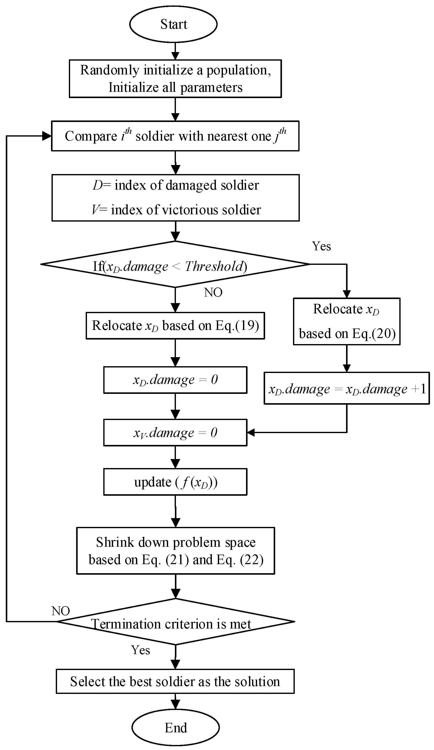
BRO is a metaheuristic algorithm which is basically inspired by the idea of battle royale games such as PUBG and Call of Duty. The algorithm was developed by Taymaz [29] in 2020 and is used for the first time in this paper for the optimal placement of DGs in a system. This algorithm envisages that each player must be randomly placed in the game space with the same number of resources and amount of strength. Each player has to compete with the other players and game-obstacles as well. Every player in the game tries to move towards a safe region and kill the opponent players. On the losing end, players’ resources or strength might be reduced or they may be eliminated from the game on account of the damage. In the end, the player possessing the highest number of kills finally wins the game. The main steps of the BRO algorithm are listed below.
Step I: This step accounts for the initialization of the algorithm parameters by determining the number of iterations, maximum threshold, and the population number.
Step II: A random population is generated within the problem space.
Step III: Each individual in the game tries to hurt the nearest opponent soldier.
Step IV: The soldier hurt by an opponent loses one point of strength.
Step V: The player that experiences damage tries to alter their position. The position within dimension (dim) can be achieved by Equation (19).
x D , d i m = x D , d i m + r ( x B , d i m x D , d i m )
wherein xD,dim represents the position of the damaged soldier, while xB,dim represents the position of best soldier found so far. r denotes a random number which is uniformly distributed from the range of 0 to 1.
Step VI: If the soldier’s strength reduces up to the extent of a predefined threshold due to damage, then this soldier dies. The player will be reallocated within the feasible region with full strength. The process is given by Equation (20).
x D , d i m = r ( u b d i m l b d i m ) + l b d i m
In Equation (20), ubdim and lbdim are the upper and lower bounds of the dimension, whereas r has a random value between 0 and 1.
Step VII: In this step, after each iteration, the search space converges towards the best solution. The process is illustrated by Equations (21) and (22). Wherein, SD corresponds to the standard deviation of the population. Moreover, lbdim and ubdim are the upper and lower bound limits of dimension dim, respectively. However, xB,dim represents the position of the best soldier, while xD,dim represents the position of the injured soldier
l b d i m = x B , d i m S D ( x d ¯ )
u b d i m = x D , d i m + S D ( x d ¯ )
Step VIII: In this step, after the completion of each iteration, the best solution is selected.
The flow chart of BRO is shown in Figure 2. For the sake of DG allocation, the following alterations are made in the conventional BRO outlined:
  • The population of soldiers is replaced with DGs’ locations and sizes.
  • The threshold selected in the current paper is 3, and a specific value is used to avoid premature convergence and to attain improved results [29].
  • The upper and lower bounds are replaced with the upper and lower limits of DGs’ location and size.
The best solution depends on a multi-objective index value.

3.2. Accelerated Particle Swarm Optimization Algorithm

APSO is the updated version of PSO and was developed by Yang in 2010 [30]. The study in [31] considers APSO for optimal DG allocation. In PSO, both global best and particle best positions are used. The diversity in this algorithm is achieved by using the particle’s best position, while for the sake of expeditious convergence, only global best position (Pg) is used in APSO. The algorithm is discussed and utilized in [32]. The velocity vector at t + 1 iteration is obtained using Equation (23).
V j t + 1 = V j t + α ε + β ( P g X j t )
For convergence of the algorithm more rapidly, the particle’s location is also updated using Equation (24) where ε is the vector containing random values between 0 and 1, while α and β accelerating constants.
X j t + 1 = ( 1 β ) X j t + β P g + α ε
The particular values of α lie within 0.1 to 0.4, while the value of β is between 0.1 and 0.7. t is the index value of each iteration and is also used in a flow chart. In the current problem, the value of alpha α is 0.2, while beta β is taken as 0.5 [30]. The position in the APSO algorithm is replaced with DG size and location. The flow chart of the APSO algorithm is shown in Figure 3 [33]. The APSO algorithm comprises the following stages that are illustrated below [32].
Step I: The first step accounts for the initialization of the basic parameters of the algorithm such as population, velocity, and number of iterations.
Step II: Similarly, the second step accounts for the evaluation of objective function value at each particle’s location.
Step III: In this step, the calculation of global best position will be carried out.
Step IV: After locating the global best position, the algorithm will update the swarm velocity and position using Equations (13) and (14).
Step V: At the end, the repetition of step 2 is done until the specific criteria are satisfied.

3.3. Genetic Algorithm

Genetic algorithm (GA) is an evolutionary optimization technique based on genetics phenomena and natural selection. Hence, the best candidate is always chosen by the natural selection process, which is dominant over the weaker ones [34]. The study in [35] also implemented GA for optimal DG allocation. The flow chart of GA is illustrated in Figure 4 [36].
This process involves selection, crossover, and mutation, and the basic steps of the methods are discussed below.
Step I: First of all, the initial chromosome population is generated, while in the current case, DGs sizes and locations are reciprocated as chromosomes.
Step II: The second step accounts for the evaluation of the fitness value of each chromosome in the population.
Step III: A new population is generated using biological evaluation, which is selection, crossover, mutation, and finally, acceptance.
Step IV: In the last step, we check the results to see if it has achieved up to the desired range; otherwise, we repeat the process from fitness calculation.

4. Mathematical Modeling of Optimization Problem

This section envisions min-max regret criteria for the optimal allocation of DG; modeling of the mentioned optimization problem and the test systems is employed to solve the optimization problem.

4.1. Min-Max Regret Criteria

The min-max regret criteria provide a robust solution for various scenarios while minimizing the worst-case regret [37]. This means that the min-max regret criteria calculate the best possible solution for all possible scenarios. The aforementioned solution then minimizes the maximum divergence between the best possible solution and the optimal solution of each corresponding scenario. This technique has been applied and implemented in [37,38], wherein S is considered as a finite set of scenarios (s1, s2, s3, …, sn), and each scenario s is the subset of S i-e (sS). Herein, the set of solutions is represented by vector X (x1, x2, x3, …, xn). f(x,s) represents the value of the solution xX at scenario sS, xs* is the optimal solution at scenario sS, and fs* = f(xs*,s) is the corresponding optimal value. In the first step, the regret value R(x,s) of each solution x under scenario s is obtained, which is represented by the following equation.
R ( x , s ) = f ( x , s ) f S
The maximum regret value of solution xX is denoted by Rmax(x), which can be further expressed as Rmax(x) = maxRmax(x,s). In the second step, the maximum regret value of each solution is obtained. In the end, the solution which possesses the minimum value among the corresponding maximum regret values is considered the minimum solution of all the solutions xX and is defined by the following equation.
min R max ( x ) = min max s ( f ( x , s ) f S )

Handling DG Allocation through Min-Max Regret Criteria

The min-max regret criteria are implemented for the day-ahead bidding strategies in [38], which inspired us to implement the current DG allocation problem incorporating multiple scenarios. The min-max regret criteria for DG allocation (at various scenarios) need several replacements in the corresponding equation of min-max regret criteria. DG allocation (sizes and locations) is considered solution x. The first step corresponds to the selection of the best allocations of DGs that are obtained at each scenario and are further considered as solutions (x1, x2, x3,…xn) and considered in vector X. The value of solution f(x,s) and regret value R(x,s) are replaced with MO and fitness value F in the current method, respectively. OMO refers to the optimal multi-objective index value which is considered as the optimal MO value. OMOs is defined as fs* in Equation (25) which is the optimal value of x at a particular scenario s. MO is obtained by each solution x at a particular scenario s. In total, 24 scenarios are taken and considered as a set S (S = (s1, s2, s3,……s24)), while each scenario signifies the specific hour of the day. In the second step, F is obtained for each solution x as a regret value for the particular scenario. The general equation mentioned earlier (Equation (25)) for the calculation of the regret value of solution x is modified according to the current method and illustrated below.
F ( x , s ) = M O O M O s
In the third step, the maximum regret value of each solution x is obtained by Equation (28).
max F ( x ) = s = 1 s = 24 F ( x , s )
M F = max F ( x )
The maximum regret value is defined in terms of maxF(x), which is the arithmetic sum of all F values of each solution x. Equation (26) is modified in accordance with the current problem of DG allocation that is represented by Equation (30), and is mentioned hereunder.
min M F ( x ) = min max M F ( X )
wherein, the solution x, which has a minimum value maxf(x), is considered as the final solution. From the fourth to tenth step, the modeling of the optimization problem has been carried out that includes the min-max criteria.

4.2. Modeling of the Optimization Problem

The main focus of the current paper is on the improvement of the power system while minimizing power system losses (active and reactive) and improving bus voltage profiles. The study is carried out under a 24 h load horizon and renewable generation. This method involves the concept of min-max regret to obtain a robust solution that incorporates the optimal allocation of DGs in the system. A total of 24 different scenarios are considered, and each of them has a unique load and renewable generation profile.
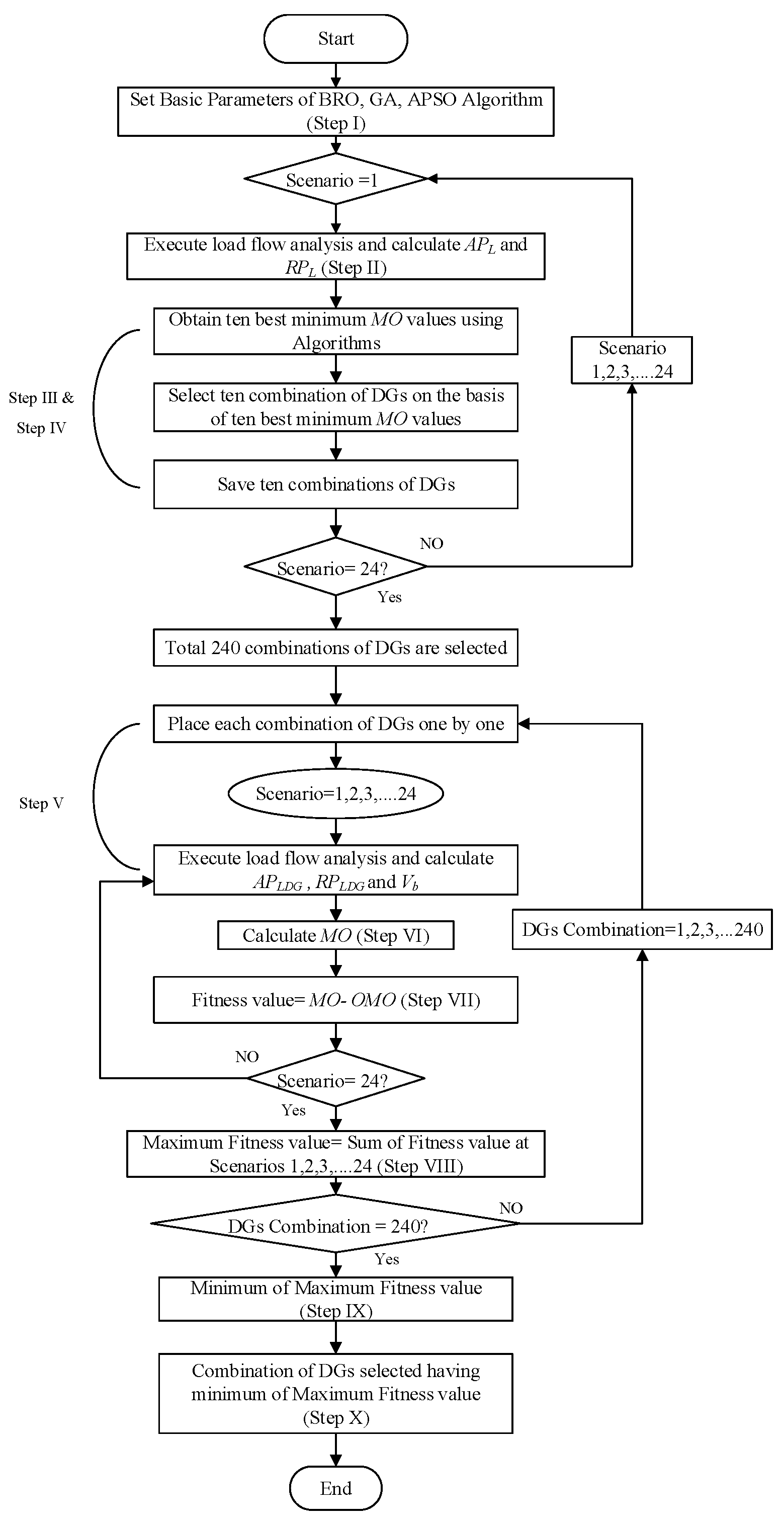
First of all, the NRLF analysis is carried out for each scenario in order to obtain the optimum parameters of DGs, which are to be introduced in the system. The consideration of DGs are realized on the basis of the minimum values of MO while using GA, APSO, and BRO, respectively. Furthermore, the obtained DGs are placed in the test system one by one in order to calculate the fitness values for each DG in a considered scenario. Afterwards, the maximum fitness value of the DG is obtained by summation of all fitness values of the DG across all scenarios, respectively. Hence, the DG devouring the least maximum fitness value is considered the desired optimal allocation of the DG for 24 h. The aforementioned approach is novel compared to the concurrent methods, as it studies the active and reactive power loss minimization and enhancement in bus voltage profiles for 24 h with a time step of one hour. The flow chart of the methodology discussed earlier is shown in Figure 5. The steps for achieving the desired objectives are mentioned hereunder.
Step I: Initialize basic parameters of BRO, GA, and APSO algorithms and set the population size and number of iterations.
Step II: Perform Newton–Raphson load flow (NRLF) without integrating DG (/s) in the system, and calculate APL and RPL for each scenario/hour. Renewable DGs produce different power for each particular scenario on account of the fluctuating nature of solar and wind energy. Moreover, the load is also fluctuating in each scenario which depends upon the demand side.
Step III: Find DG (/s) with the optimal allocation (i.e., sizes and locations) for each scenario based on minimum MO values calculated through BRO, GA, and APSO algorithms.
D G C = [ d g 1   d g 2   d g 3 ]
M O S = 1 , 2 , 3 , , 24
In Equation (31), DGC represents a combination of DGs that would be placed in the test system, dg represents the optimal allocation of DG, whereas the coefficient of dg denotes the exact number of DGs allocated in the test system. The optimal allocation of DG means the optimal size and location of DG. S represents the scenario.
Step IV: Sort MO values in ascending order that are obtained for each scenario. Onward, select the ten best DGCs corresponding to ten minimum MO values of the particular scenario. In total, 24 scenarios are formed for a day, and so each specific scenario is studied for an hour. Therefore, S reaches up to 24.
M O S = 1 , 2 , , 24 = [ M O 1   M O 2   M O 3   M O 10 ]
D G S S = 1 , 2 , 24 = [ D G C 1   D G C 2   D G C 3   D G C 10 ]
where, in Equation (32), MOS is the set of minimum MO values obtained for scenario S, and MO1 to MO10 are sorted minimum MO values for scenario S. In Equation (33), DGSS is the set of DGCs (i.e., DGC1 to DGC10) selected corresponding to the minimum MO values obtained for the same scenario S. Ten DGCs are obtained per scenario resulting in a total of 240 DGCs for 24 scenarios.
Step V: Place the DGCs in the system one by one and calculate APLDG, RPLDG, and Vb for each scenario.
Step VI: Calculate MO for each DGC using Equation (8). In each scenario, it is carried out while considering the parameters APL, RPL, APLDG, RPLDG, and Vb that were calculated during Step II and Step V.
M O D G C 1 = [ M O S 1 , M O S 2 , , M O S 24 ]
M O D G C 2 = [ M O S 1 , M O S 2 , , M O S 24 ] M O D G C 240 = [ M O S 1 , M O S 2 , , M O S 24 ]
Here, in Equation (34), MODGC1 to MODGC240 are the set of MO values, calculated by placing the DGC1 to DGC240, respectively, for all 24 scenarios. Similarly, MOS1 to MOS24 are MO values that are calculated for specific DGC from scenario S1 to scenario S24.
Step VII: Compute fitness value F for particular DGC under scenarios S1 to S24 using Equation (36).
O M O = [ O M O S 1 , O M O S 2 , ,   O M O S 240 ]
F D G C 1 , S 1 = [ M O S 1 O M O S 1 ]
F D G C 1 , S 2 = [ M O S 2 O M O S 2 ] F D G C 1 , S 24 = [ M O S 24 O M O S 24 ]
In Equation (35), OMO is the set of optimal MO values obtained for each scenario, whereas OMOS1 to OMOS24 are optimal values for scenarios S1 to S24. However, the optimal MO value means the maximum achievable minimum MO value at a particular scenario. To obtain OMO values, the algorithm parameters are different than the parameters for obtaining MO values.
Step VIII: Calculate maximum fitness value (MF) by calculating arithmetic sum of all fitness values of the particular DGC using Equation (37).
M F D G C 1 = S = 1 S = 24 ( F D G C 1 , S 1 , F D G C 1 , S 2 , , , F D G C 1 , S 24 )
M F D G C 2 = S = 1 S = 24 ( F D G C 2 , S 1 , F D G C 2 , S 2 , , , F D G C 2 , S 24 ) M F D G C 240 = S = 1 S = 24 ( F D G C 240 , S 1 , F D G C 240 , S 2 , , , F D G C 240 , S 24 )
Step IX: Sort MF of all DGCs and find the minimum of maximum fitness among all DGCs using the equation mentioned hereunder.
min M F = min [ M F D G c 1 , M F D G c 2 , . , M F D G c 240 ]
Step X: The combination of DGs (i.e., DGC) with the least value of MF is considered the desired solution for all scenarios.

4.3. Test System

This paper considered CIGRE MV benchmark model as a test system for implementing the optimization problem discussed in the above section.

4.3.1. CIGRE MV Benchmark Model

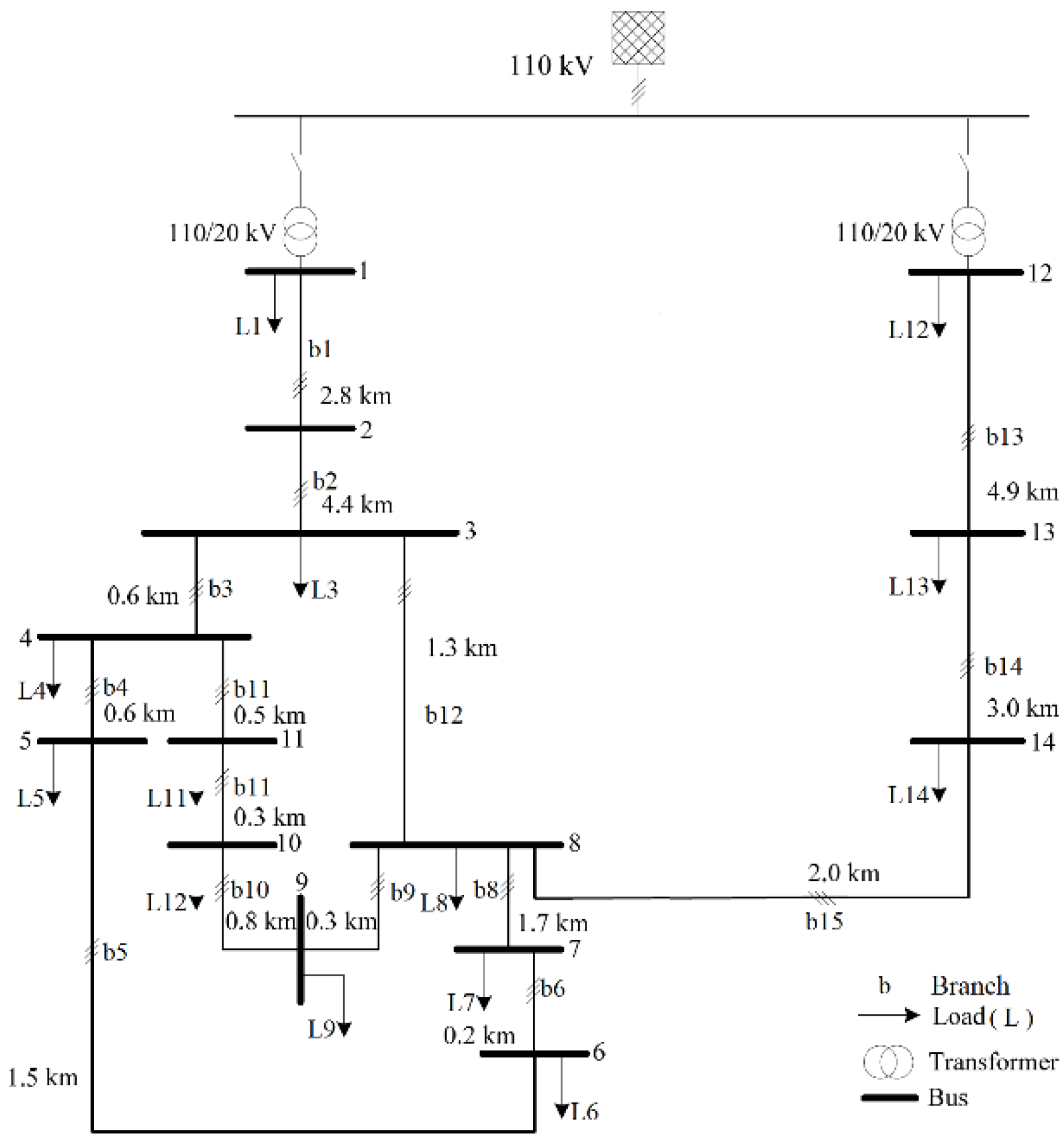
The model consists of 14 buses and 15 branches, as shown in Figure 6. Different types of DGs are connected to altered buses in the test system [39]. Almost every DG type has stable output power, but two of them have variations in output power on account of the fluctuation in resources at different times of the corresponding day. The aforementioned DGs encompass solar and wind utility resources. The model also includes a battery, but it is neglected in this study because of its charging and discharging behavior after a specific period.

4.3.2. Simulation Setup

The optimal allocation of DGs for a 24 h load horizon is already discussed in the methodology section and is executed by various algorithms. The aforementioned simulations are carried on MATLAB. The parameters of each algorithm are listed in Table 2, and these parameters are utilized during the computation process only.

4.3.3. Input Data Configuration

The 24 h load data is utilized for the CIGRE model with a time step of one hour [40]. The residential and commercial loads are connected to different buses with different power factors. The net active and reactive power loads connected to the European version of the CIGRE model are calculated on an hourly basis. The active and reactive power load values for each specific scenario is outlined in Appendix A (Table A1 and Table A2). In Table A1 and Table A2, the left-most column “Scenarios” represents hours of the day, while L1 to L14 represents the loads at each specific bus. In the CIGRE model, four different ratings, i.e., 40 kW, 30 kW, 20 kW, and 10 kW of solar DGs, are already installed, while the output power curve of each type of DG rating is shown in Figure 7a. Each curve corresponds to the product of the power per unit curve of PV [41] and the rating of the solar DG. The wind DG used in the CIGRE model has a rating of 1500 kW, while power extracted at each scenario from the DG is shown in Figure 7b. The wind power curve is the product of its rating and wind DG per unit curve [33]. The scenario represents the specific hour of the day.

5. Results

This section exhibits the effectiveness of the proposed methodology and algorithms on CIGRE’s MV Benchmark model. It permits the voltages to be computed across all buses and active and reactive power losses for a system overall and on lines. The study has been conducted by placing three DGs in the test system. These DGs have the same active and reactive power that is expressed in kW and kvar. The minimum capacity limit is 10 k, whereas the maximum limit accounts for 500 k. In the model mentioned, twenty-four different scenarios are considered. Each scenario corresponds to a single hour of the respective day and has a unique load and generation profile. In each scenario, the load and power of solar and wind DGs fluctuate. The active and reactive power loss minimization procedure is carried out according to the methodology mentioned earlier. Three DGs are incurred in the CIGRE model by optimizing system constraints (i.e., optimal size and location). Each DG among them has been used for the consideration of executing the mentioned algorithm for all scenarios. At the initial stage, the ten best optimal allocations of DGs are obtained for each scenario, and 240 optimal allocations are considered for 24 scenarios. The best DG allocations among ten optimal allocations for each particular scenario are represented in Table 3. At the finale stage, the single robust optimal allocation (locations and sizes) of DGs among all 240 allocations are obtained for 24 scenarios through min-max criteria and represented in Table 4. However, the whole methodology is carried out 20 times for its long-term evaluation, and during each process, a single robust allocation is obtained; therefore, among 20 whole findings, robust optimal locations and sizes obtained are as modes and an average of 20 results, respectively. Hence, all other results are deduced by extracting their average values.
The optimal MO values (OMO) obtained using each algorithm are listed in Table 5. MO values are basically obtained at the time of computation process, while OMO values are obtained before simulations, and these values are maximum minimum achievable MO values at a particular scenario. In current paper, these OMO values are obtained at 2000 iterations with a population size of 100 using each algorithm. The fitness value is calculated by the difference of MO and OMO as described in Section 4.2 step VIII. The all findings achieved through the simulations are summarized in Table 6. DGs’ active and reactive powers are the same and are expressed in kW and kvar, respectively.

5.1. MO and Fitness Values

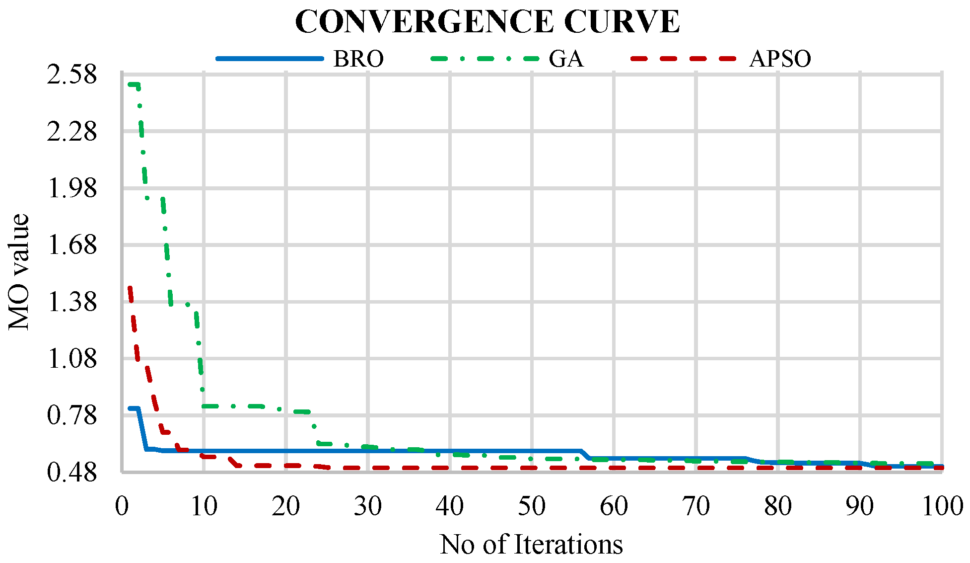
GA, APSO, and BRO are used to find optimal locations and sizes of DGs for the sake of active and reactive power loss minimization and bus voltage improvement. It has been performed by searching out the minimum value of MO for each scenario. The minimum MO values obtained by each algorithm for all scenarios are shown in Figure 8, whereas the MO convergence curve of APSO, GA, and BRO algorithms for a single scenario is shown in Figure 9. Furthermore, these MO values are used to calculate the fitness values and maximum fitness (MF) values of DGs. The minimum MF values obtained through each algorithm are illustrated in Table 6.

5.2. Active Power Losses

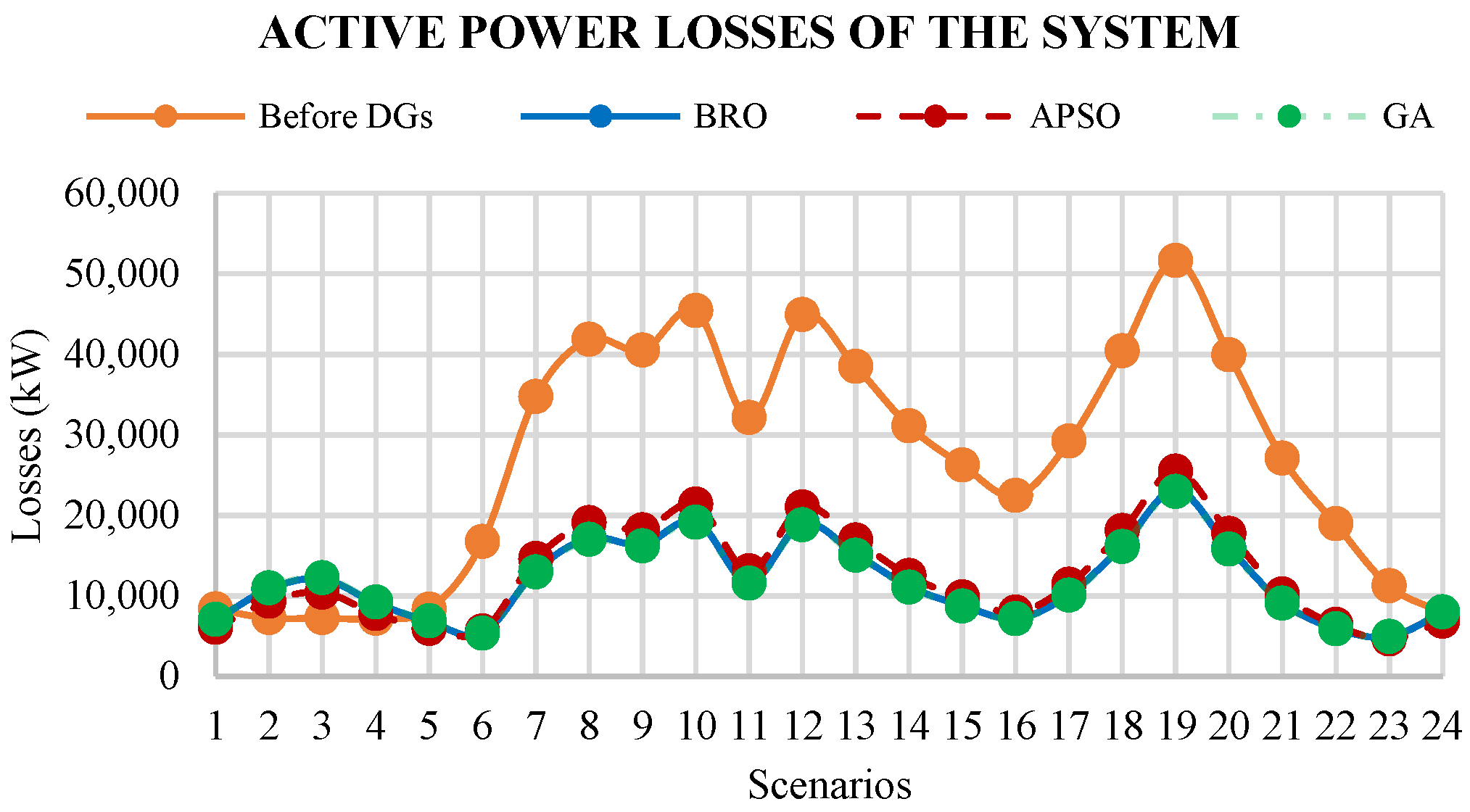
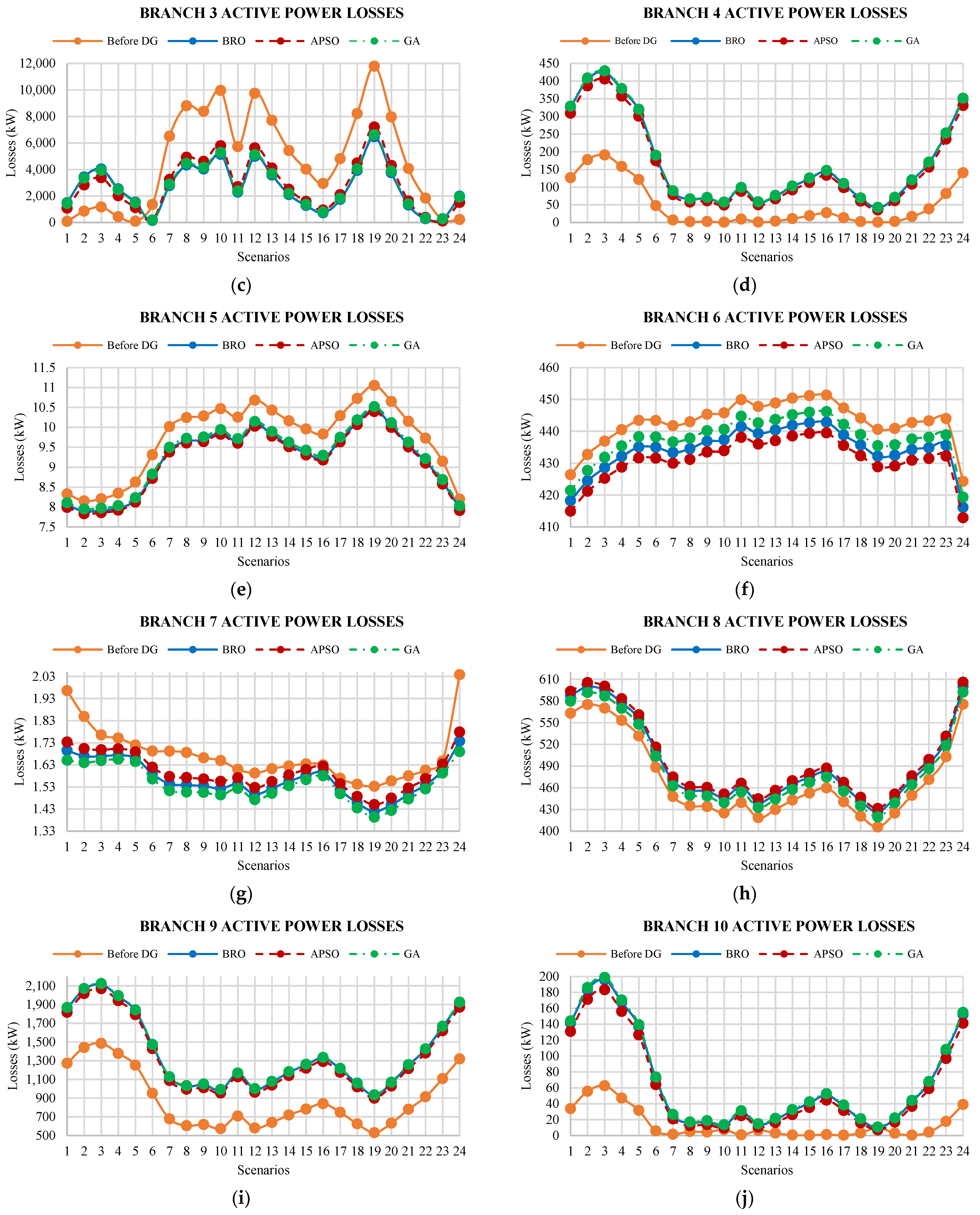
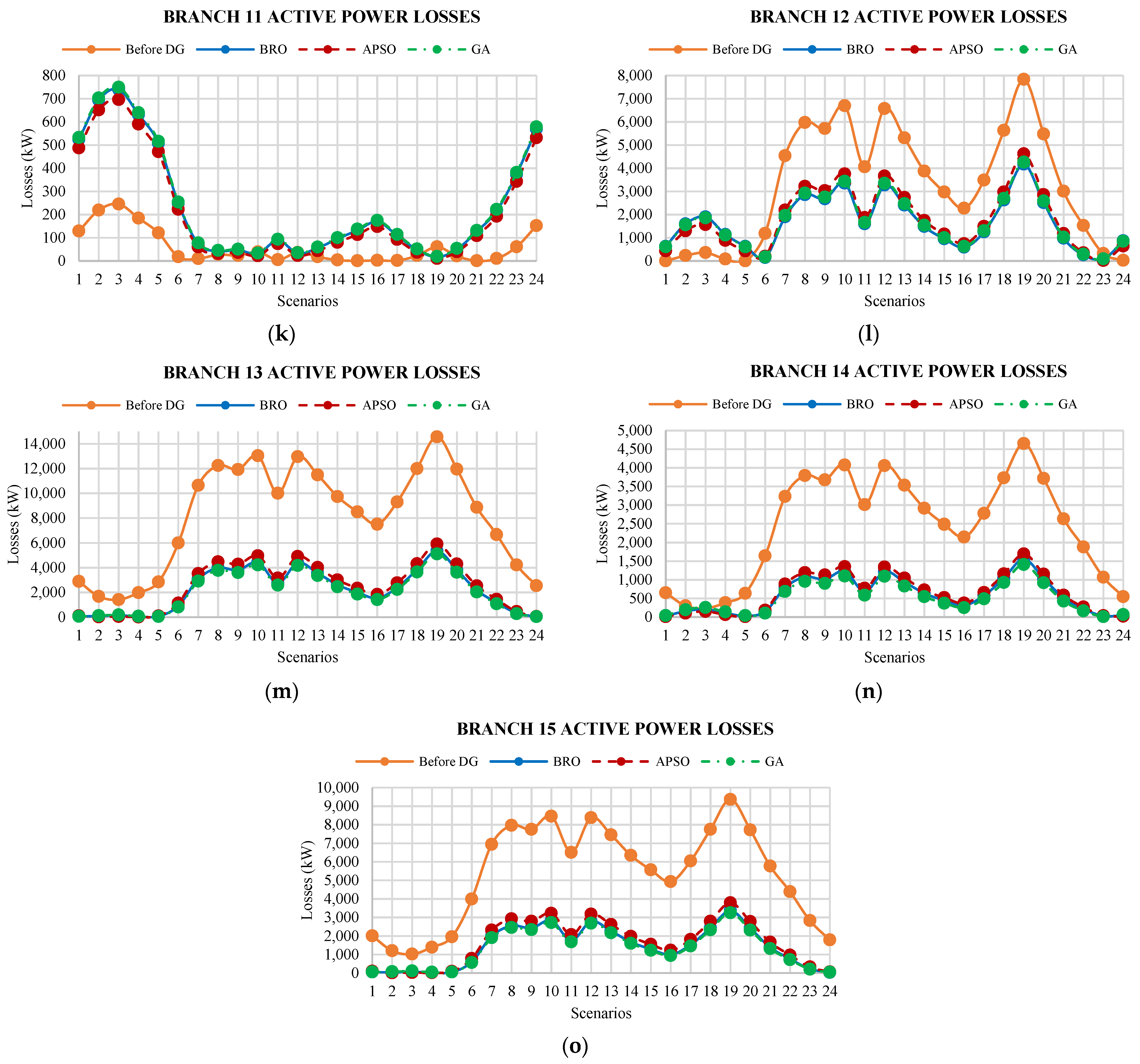
The active power loss curves for all scenarios using various algorithms are shown in Figure 10. Herein, the orange curve shows the losses before the placement of DGs. A summary of these results is also presented in Table 6. The active power loss curves of branch 1 to branch 15, for all scenarios, are shown in Figure 11, whereas the average active power losses of the branches are represented in Table 7.

5.3. Reactive Power Losses

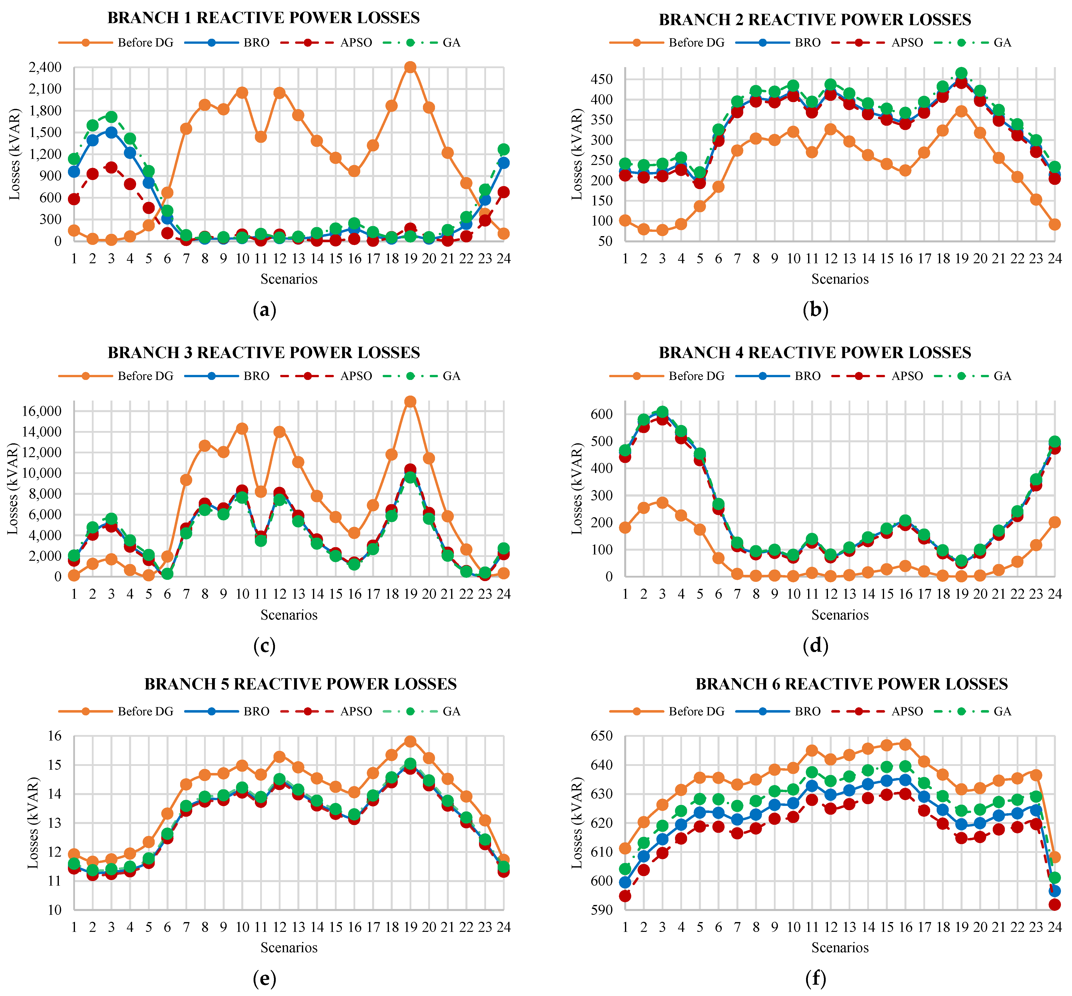
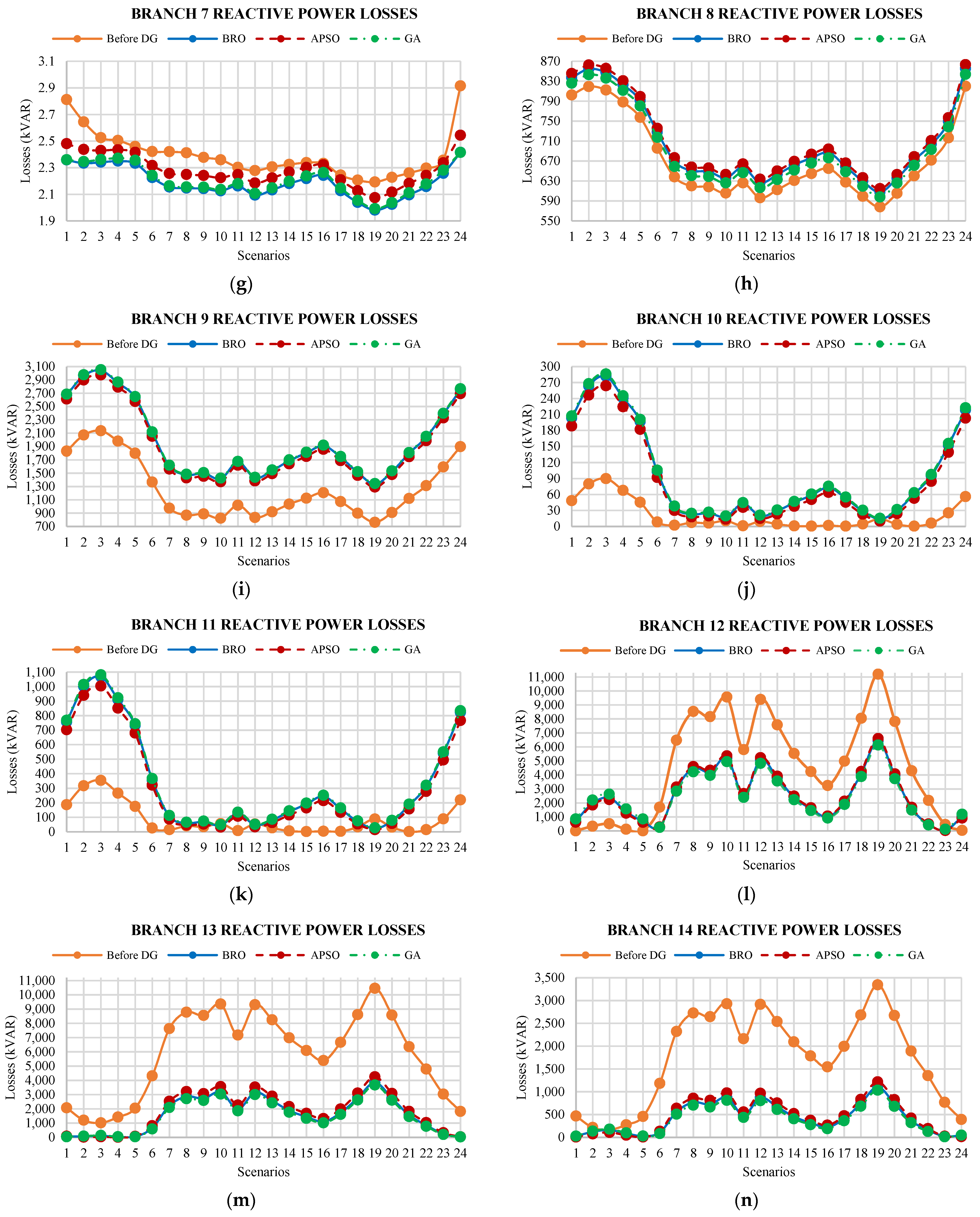
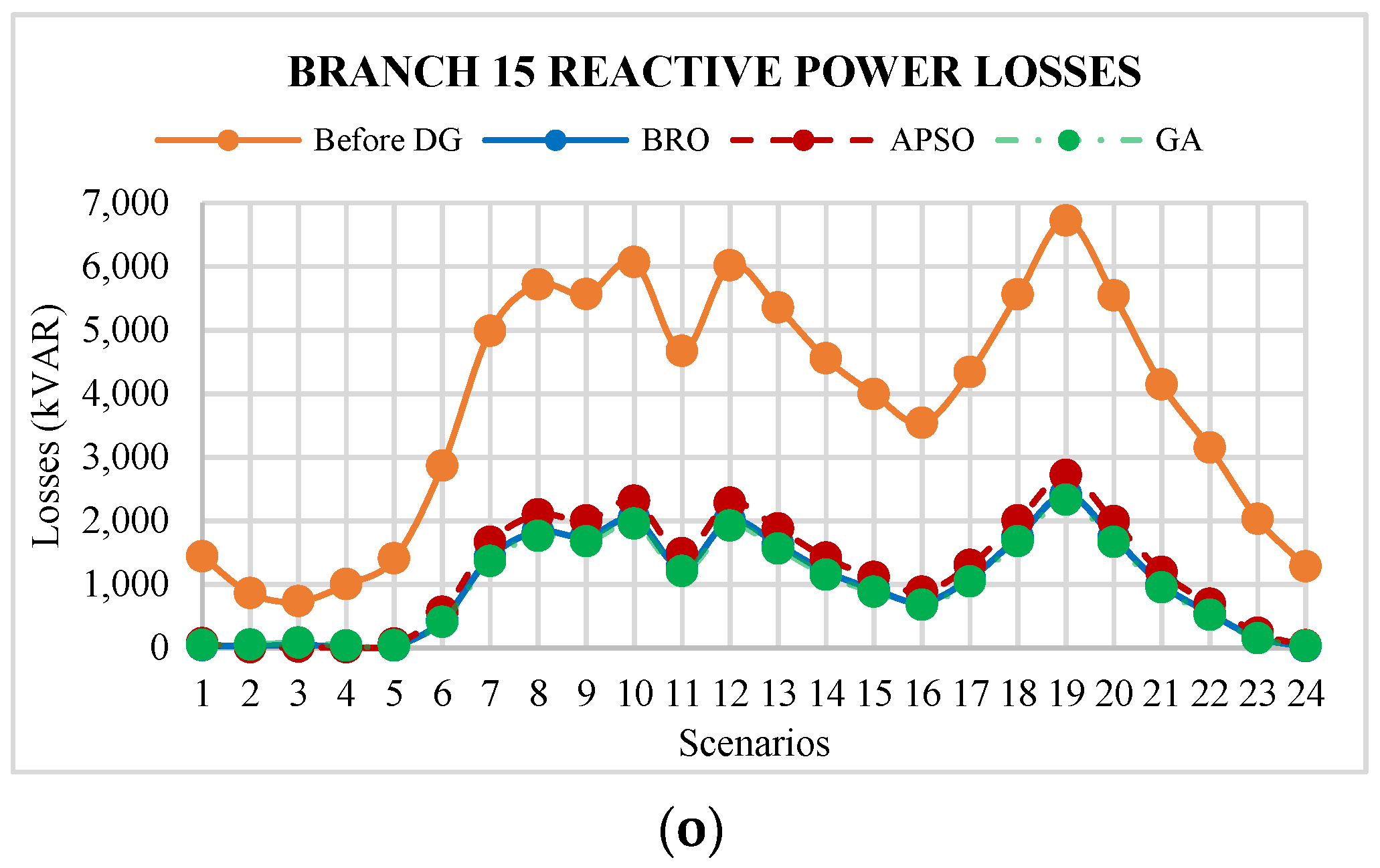
The reactive power loss curves for each scenario of the studied case are illustrated in Figure 12. A summary of these results is also presented in Table 6. The reactive power loss curves of branch 1 to branch 15, for all scenarios, are shown in Figure 13, whereas average reactive power losses of branches are presented in Table 8.

5.4. Bus Voltage Profiles

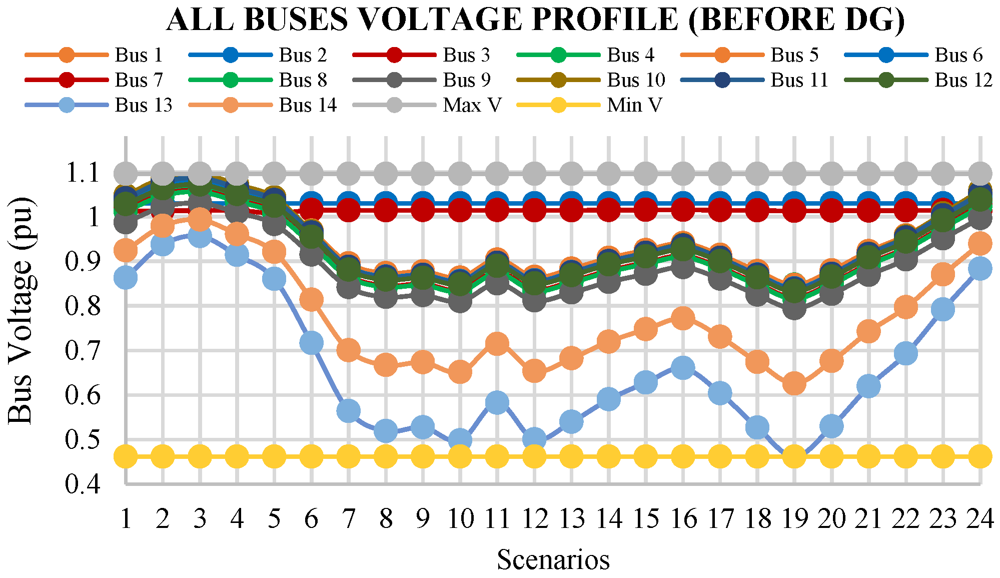
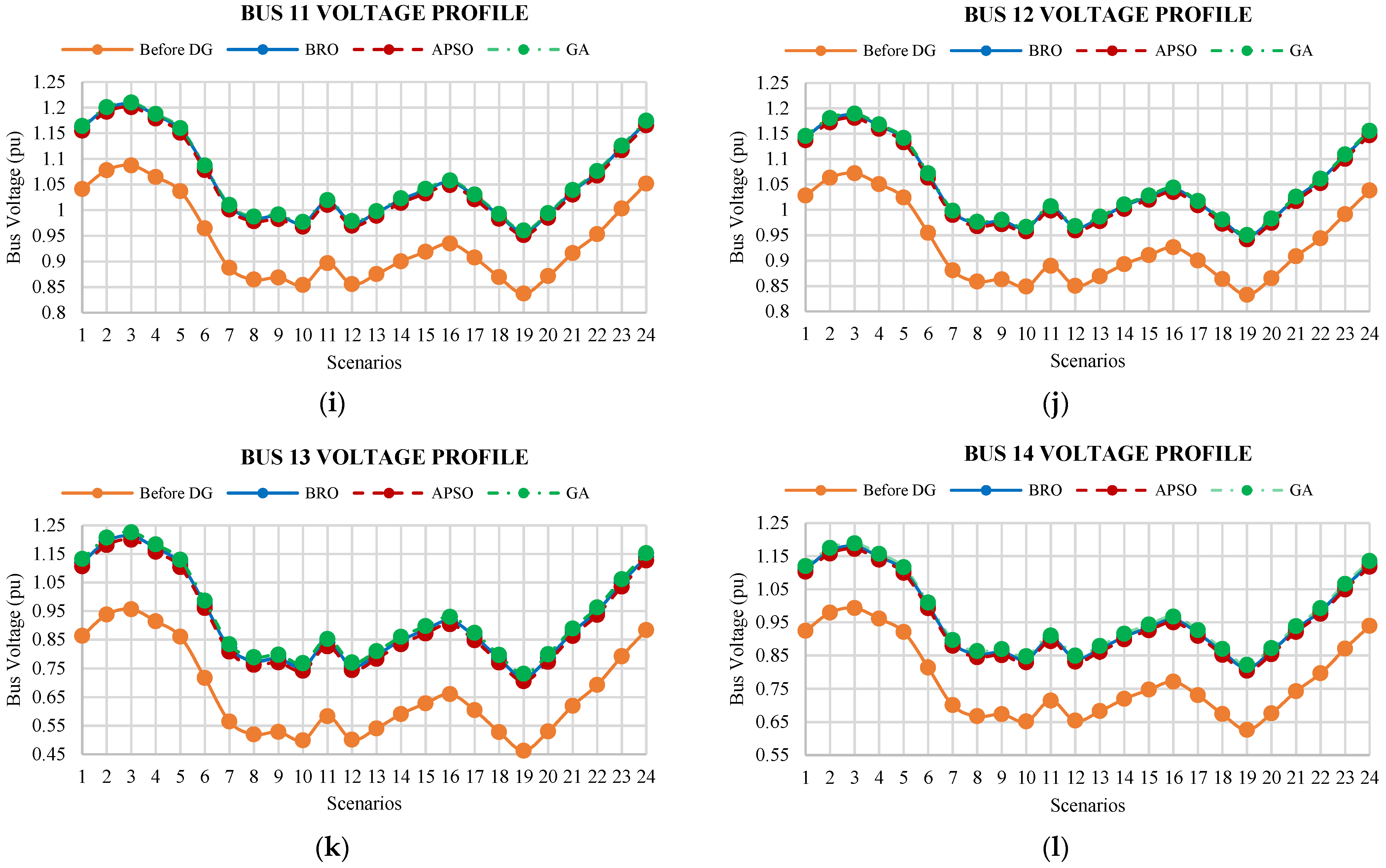
Voltage curves of buses for all scenarios of the existing system are shown in Figure 14. A summary of these results is also incorporated in Table 6, whereas the average voltages of all buses are illustrated in Table 9. After the placement of DGs for all scenarios, the voltage curves of bus 3 to bus 14 are shown in Figure 15. The voltage curves of bus 1 and bus 2 are not presented because of their negligible variations in all scenarios.

6. Discussion

6.1. MO and Fitness Values

Minimum MO values are obtained while utilizing all three algorithms to determine the best DG allocations at each particular scenario. Figure 8 visualizes the minimum MO values obtained with the algorithms at all scenarios. The curve shows that MO values are high during early and late scenarios that are from 1 to 6 and 22 to 24. If we compare our MO curve with Figure 10 and Figure 12, it shows that the actual system losses at these scenarios are less compared to other scenarios of the day because of the minimum load demand at these particular scenarios. Due to the minimum demand at these scenarios, minimization in losses would also be at a minimum. Due to this fact, the active and reactive power loss index values are high, as the small ratio lies between losses before and after DG. Following this logic, the MO values are high at these particular scenarios. However, in the scenarios from 7 to 21, the load demand is high which causes high losses. So, by optimal DG allocation, the losses become minimum, and as a result, the ratio between losses before and after DG can increase. This can cause a lower MO value. The ratios in active power losses and reactive power losses cause variation in MO value when considering Equation (8). Therefore, during the daytime, MO values are lower as compare to the nighttime MO values.
Comparing all three algorithms, the average MO value obtained using the APSO algorithm seems to be the most minimal out of all the algorithms in Figure 8. By following the curve, the APSO MO’s value lies below compared to other algorithms in all scenarios. So, it seems that APSO has a better performance in terms of MO values.
The convergence curves of the algorithm’s MO values at a single iteration are shown in Figure 9. The best one is APSO which has a fast convergence, while BRO and GA are second. The searching process of BRO is good in that its searching starts from minimum values as compared to other algorithms. Furthermore, these MO values are used to calculate the fitness values for each considered DG. In the next step, the maximum fitness values of all DGs are calculated. The maximum fitness values obtained using the APSO, GA, and BRO algorithms are 6.39, 6.69, and 6.48, respectively, which is also mentioned in Table 6. In terms of maximum fitness value, APSO has a better output.

6.2. Active Power Losses

The results from Section 5 demonstrate appealing features of the designed methodology. Active power losses are analyzed in two ways—losses occurring at the overall system and along each branch of the system. The following points are obtained after analyzing the active power losses of the system using the designed methodology.
  • Figure 10 and Table 6 show that the maximum active power loss that occurred in the 19th scenario is 51,604.96 kW. This loss is minimized to 25,471.47 kW, 23,123.32 kW, and 22,925.5 kW by optimally allocating DGs via the usage of the APSO, BRO, and GA algorithms.
  • The average active power loss arising in the existing system is 26,617.93 kW in all scenarios, which is reduced to 11,743 kW, 12,502.73 kW, and 11,794.14 kW using GA, APSO, and BRO algorithms, respectively.
  • The existing active power loss from scenarios 2 to 4 are lesser than the losses calculated after the placement of DGs. Hence, the results described above signify that the proposed method, when applied to allocating DGs in the system, helps to reduce the overall total active and reactive power losses in the system for all the considered scenarios. Therefore, the planned DGs deliver the same active power for a whole day. However, the power demand for scenarios 2 to 4 is less than the generated power, and this causes an increase in active power losses.
  • The total active power losses for all scenarios are considered as active energy losses of 24 h. After the placement of DGs optimally, the active energy losses are calculated as 300,065.4 kWh, 281,838 kWh, and 283,059.7 kWh for APSO, GA, and BRO, respectively. Hence, it shows that 53.03%, 55.88%, and 55.69% of reduction in active energy loss has been seen in the system compared to the actual energy loss before the placement of DGs.
  • Figure 11 shows that the active power losses are lower for most branches’ initial and final scenarios. These scenarios incorporate off-peak hours, including late-night hours in which the load requirement is lower than the peak hours during the daytime. Therefore, the system losses are lower during the late-night period.
  • The maximum loss occurs in the 19th scenario for most of the branches. The actual peak active power loss of 14,569.43 kW occurs among all branches of the system. This loss is minimized to 6619.197 kW, 7199.756 kW, and 6465.435 kW by the optimal allocation of DGs using the GA, APSO, and BRO cases, respectively.
  • The actual minimum loss of 0.346432 kW occurred among all branches of the system is further increased up to 1.392466 kW, 1.45 kW, and 1.384796 kW while placing DGs using the GA, APSO, and BRO algorithms, respectively.

6.3. Reactive Power Losses

Reactive power losses are analyzed in two ways—reactive power losses occurring in the overall system and reactive power loss occurring in each branch of the system. The main analysis of the outcome after analyzing the reactive power losses of the system is mentioned hereunder.
  • Figure 12 and Table 6 show that the maximum reactive power loss is 53,490.16 kvar which occurs for the 19th scenario. This loss is minimized to 28,191.04 kvar, 25,669.27 kvar, and 25,836.27 kvar after the incursion of DGs in the system using APSO, BRO, and GA.
  • The actual average reactive power loss for all scenarios is 26,805.49 kvar. This loss is minimized to 14,412.65 kvar, 13,813.92 kvar, and 13,999.75 kvar after the placement of DGs using APSO, BRO, and GA. It shows that BRO has a better performance in the case of reactive power loss minimization.
  • The present system’s reactive power losses from scenarios 1 to 5 are less than the existing system before the placement of DGs. The proposed method is applied to allocate the optimal size and location of DGs while reducing the system’s overall total reactive power losses for all considered scenarios. Therefore, the planned DGs deliver the same power for a whole day. However, the power demand from scenarios 1 to 5 is less than the generated power which has caused the increase in loss.
  • The total reactive power losses for all scenarios are considered as reactive energy losses of 24 h. After the placement of DGs, reactive energy losses are at 345,903.6 kvarh, 335,994.1 kvarh, and 331,534.010 kvarh using APSO, GA, and BRO, respectively.
  • The actual peak loss of 16,907.7 kvar that arises at branches is minimized to 9493.322 kvar, 10,325.97 kvar, and 9272.794 kvar using GA, APSO, and BRO.
  • The actual minimum loss of 0.498524 kvar at branches is increased up to 1.98112 kvar, 2.074574 kvar, and 1.992093 kvar by using GA, APSO, and BRO.
  • Figure 13 shows that reactive power losses for initial and last scenarios are lower. These scenarios represent late-night hours, and their load requirement is lower compared to daytime hours. Accordingly, the system losses are lower during the late-night period.
  • The maximum reactive power loss arises for the 19th scenario at most branches. The maximum average reactive power loss occurs at branch 3. This loss is best minimized to 3811 kvar using BRO.
  • The average reactive power losses across branches 3, 5, 7, 12, and 13 are also best minimized using BRO.
  • The average reactive power losses across branches 1, 2, 4, 6, 9, 10, and 11 are best minimized using APSO.
  • The GA attains a better reactive power losses minimization for branches 8, 14, and 15.
  • For busses 2, 4, 8, 9, 10, and 11, the average reactive power losses are increased after the placement of DGs.

6.4. Bus Voltage Profiles

The following analysis has been devised while studying bus voltage profiles.
  • Figure 14 and Table 6 show that the actual minimum voltage across all buses is 0.4621 pu. It increased up to 0.726061 pu, 0.705585 pu, and 0.732564 pu by individually using BRO, APSO, and GA.
  • The maximum voltage before the allocation of DGs is 1.0958 pu, which was enhanced up to 1.225032 pu, 1.215942 pu, and 1.226702 pu by using the BRO, APSO, and GA.
  • Figure 15 shows that the proposed method improves bus voltage profiles for all scenarios. The proposed BRO algorithm attains better performance in terms of voltage profile improvement as compared to the ASPO and GA.
  • The average minimum voltage before the placement of DGs is 0.6654 pu at bus 13, which is improved to 0.9358 pu, 0.9088 pu, and 0.9293 pu by using the GA, APSO, and BRO.

6.5. Main Findings and Comparison of Algorithms

MO, maximum fitness, and other results are discussed in detail. A summary of the main findings and comparison of BRO, APSO, and GA is presented in Table 6. The results are complicated as none of the algorithms perform outstanding in all outcomes, and hence, each algorithm has its own significance in various results. The current work clarified and investigated BRO algorithm’s performance for DG allocation for the first time.
BRO secures better outcomes in obtaining the least minimum and maximum branch losses (active and reactive) and minimum total reactive power losses (reactive energy losses) as compared to other algorithms. However, the performance of the GA holds in Vmax and has the least total active power losses (active energy losses) (ref Table 6). The performance of APSO is also not forgettable as the least MO and maximum fitness values are obtained using this algorithm.

7. Conclusions

This paper presents robust optimal DG allocation in the presence of a 24 h load profile while considering the supplied power fluctuations in renewable energy-based DGs. The performance is tested using the CIGRE benchmark model. A total of 24 scenarios are designed to study the specific load and generation profiles during the day. For each scenario, DGs’ sizes and locations are determined on behalf of minimum MO values. Moreover, a robust DG allocation is determined for all scenarios on account of the min-max regret criteria. Results achieved are promising and further show validation of the minimization of total system losses, and bus voltage profiles are significantly improved using the devised method. The BRO algorithm is implemented for the first time for optimal DG allocation.
The maximum active and reactive line losses in the actual system are, respectively, 14,569.43 kW and 16,907.7 kvar. These are minimized to 6465.435 kW and 9272.794 kvar using BRO. The maximum losses reduction obtained with GA are, respectively, 6619.197 kW and 9493.322 kvar. In the case of APSO, maximum line losses are lessened to 7199.756 kW and 10,325.97 kvar. The minimum actual bus voltages for all scenarios are increased up to 0.726061 pu, 0.732564 pu, and 0.705585 pu, respectively, using BRO, GA, and APSO. The system results show that the total active energy losses (active power losses for all scenarios) are minimized to 55.69%, 55.88%, and 53.03% using BRO, GA, and APSO algorithms, respectively, for all scenarios. The reactive energy losses of the system (reactive power losses for all scenarios) are minimized to 48.47%, 47.77%, and 46.23% using BRO, GA, and APSO algorithms, respectively.
It confirms that the proposed BRO-based DG deployment outperforms in terms of the system reactive power losses compared to GA and APSO-based deployment. Moreover, the bus voltage profile improvement obtained by BRO provided better results as compared to the results obtained from GA and APSO. The aforementioned outcomes achieved using the proposed technique affirms the potential of integrating the proposed BRO-based DG deployment approach in contemporary smart grids. The losses in few branches have been found to be increased using the suggested method. A study on the minimization of this impact is in progress.
In the future, a battery storage system can also be introduced, and a detailed analysis of system faults and stability must be studied at multiple points. The incorporation of different types of hybrid DGs can improve a system’s stability while minimizing its losses. Investigating this point is another research axis. However, the real system can lead towards certain practical challenges. Firstly, the actual grid data will be needed to investigate the incorporation of DGs with an optimal allocation of resources. Secondly, the actual renewable data pattern will also be required. It will necessitate the integration of appropriate sensors at the particular areas to properly map the grid and renewable resource data patterns.

Author Contributions

Conceptualization, A.A., S.M.Q. and A.W.; methodology, A.A. and A.W.; implementation, A.A.; validation, S.M.Q. and A.W.; formal analysis, N.U. and A.A.A.A.; investigation, A.A., S.M.Q., A.W. and N.U.; resources, A.W. and A.A.A.A.; writing—original draft preparation, A.A., S.M.Q. and A.W.; writing—review and editing, A.W., A.A.A.A. and N.U.; visualization, A.A., S.M.Q. and A.W.; supervision, A.W., N.U. and A.A.A.A.; project administration, S.M.Q., A.W. and A.A.A.A.; funding acquisition, A.A.A.A. All authors have read and agreed to the published version of the manuscript.

Funding

This research work is supported by Taif University Researchers Supporting Project number (TURSP-2020/121), Taif University, Taif, Saudi Arabia.

Institutional Review Board Statement

Not applicable.

Informed Consent Statement

Not applicable.

Data Availability Statement

Not applicable.

Acknowledgments

The research is technically supported by Bahria University under HEC’s NRPU (20-14578/NRPU/R&D/HEC/2021). The authors acknowledge the financial support from Taif University Researchers Supporting Project Number (TURSP-2020/121), Taif University, Saudi Arabia.

Conflicts of Interest

The authors declare no conflict of interest.

Appendix A

Table A1. Active Power Loads (kW).
ScenariosBus 1
L1
Bus 2
L2
Bus 3
L3
Bus 4
L4
Bus 5
L5
Bus 6
L6
Bus 7
L7
Bus 8
L8
Bus 9
L9
Bus 10
L10
Bus 11
L11
Bus 12
L12
Bus 13
L13
Bus 14
L14
15477.400.00146.86110.61186.42140.4425.82150.38193.64144.7584.515535.1111.48165.32
25979.110.00154.41126.80213.70160.9924.86172.39186.47161.7296.886034.6911.05169.00
34072.670.00111.7979.59134.13101.0520.66108.20154.91105.9960.814118.849.18127.96
43595.820.0090.9378.24131.8699.3313.87106.37103.9998.4759.783626.816.1697.88
54597.970.00134.9080.93136.41102.7628.21110.03211.57114.1961.844661.0312.54161.34
65909.310.00173.52103.87175.06131.8836.34141.21272.53146.6779.365990.5316.15207.65
79490.970.00265.10180.75304.64229.5050.72245.74380.40244.12138.109604.3522.54307.12
813,296.340.00365.78258.99436.50328.8367.89352.11509.20345.53197.8813,448.1030.18419.34
914,403.680.00401.49275.18463.78349.3876.50374.12573.75371.00210.2514,574.6834.00464.45
1014,187.400.00395.38271.13456.96344.2475.31368.62564.79365.49207.1614,355.7333.47457.32
1114,935.670.00410.45291.36491.06369.9376.02396.12570.16388.40222.6215,105.6033.79470.20
1212,840.910.00344.61258.99436.50328.8360.70352.11455.27339.14197.8812,976.6026.98388.18
1314,914.630.00387.12314.30529.71399.0563.11427.30473.34402.18240.1415,055.7128.05425.34
1413,909.770.00373.27280.57472.88356.2365.74381.45493.07367.38214.3714,056.7329.22420.44
1512,629.510.00349.24244.15411.49309.9965.50331.94491.27327.07186.5412,775.9329.11401.81
1611,659.240.00333.05214.48361.48272.3166.46291.59498.45295.24163.8711,807.7929.54391.61
1710,841.010.00309.47199.64336.47253.4761.68271.42462.59274.65152.5310,978.8827.41363.73
1812,347.420.00303.26277.88468.33352.8142.55377.79319.15343.80212.3112,442.5418.91318.65
1914,323.990.00332.06342.62577.45435.0238.25465.81286.88411.27261.7814,409.4917.00331.29
2016,001.410.00357.46396.58668.39503.5235.14539.17263.57467.92303.0016,079.9615.62343.89
2114,305.180.00320.67353.41595.64448.7232.03480.48240.26417.63270.0214,376.7914.24309.57
2212,028.670.00275.30291.36491.06369.9330.12396.12225.91347.60222.6212,096.0013.39271.30
2310,175.300.00236.45242.80409.22308.2827.49330.10206.19291.79185.5110,236.7512.22236.44
247669.130.00188.29172.66291.00219.2226.39234.74197.94213.58131.927728.1211.73197.79
Table A2. Reactive Power Loads (kvar).
ScenariosBus 1
L1
Bus 2
L2
Bus 3
L3
Bus 4
L4
Bus 5
L5
Bus 6
L6
Bus 7
L7
Bus 8
L8
Bus 9
L9
Bus 10
L10
Bus 11
L11
Bus 12
L12
Bus 13
L13
Bus 14
L14
15180.280.00124.9666.23111.6284.0828.0490.04210.2797.8450.605233.0112.46153.49
25664.390.00128.1175.92127.9596.3927.00103.21202.48107.5958.005715.1712.00153.67
33847.520.0096.5647.6580.3160.5022.4364.78168.2272.4136.413889.719.97120.21
43409.690.0074.3346.8478.9559.4715.0663.68112.9264.9635.793438.016.6987.88
54329.620.00121.2348.4681.6761.5230.6365.88229.7480.5937.024387.2413.61156.15
66974.130.00156.0162.19104.8178.9639.4684.55295.94103.5547.515638.4017.54201.03
78958.810.00231.48108.22182.40137.4055.08147.13413.07168.1282.699062.3924.48290.95
812,559.960.00316.39155.06261.34196.8873.73210.82552.94236.28118.4812,698.6232.77394.39
913,597.420.00350.11164.75277.68209.1883.07223.99623.03255.26125.8813,753.6636.92439.57
1013,393.390.00344.74162.33273.59206.1181.77220.70613.29251.43124.0313,547.1936.34432.78
1114,109.200.00354.79174.45294.01221.4982.55237.17619.13265.46133.2814,264.4636.69442.00
1212,143.840.00293.40155.06261.34196.8865.92210.82494.37229.34118.4812,267.8129.30360.55
1314,126.400.00322.31188.18317.15238.9268.53255.83514.00268.12143.7714,255.2930.46387.89
1413,154.720.00317.78167.98283.12213.2871.39228.38535.41248.43128.3513,288.9931.73390.51
1511,927.130.00303.06146.18246.37185.6071.13198.74533.47224.19111.6912,060.9131.61378.85
1610,993.470.00294.73128.41216.42163.0472.17174.58541.25205.5598.1111,129.2132.07374.77
1710,222.300.00273.76119.53201.45151.7666.98162.50502.31191.1591.3210,348.2729.77347.98
1811,722.940.00242.61166.37280.40211.2346.21226.19346.56224.27127.1111,809.8420.54280.61
1913,631.720.00253.68205.14345.73260.4541.54278.89311.51262.80156.7313,709.8418.46279.10
2015,250.040.00264.43237.44400.18301.4738.16322.81286.20295.37181.4215,321.8216.96280.08
2113,631.680.00237.94211.60356.62268.6634.79287.68260.89263.91161.6713,697.1015.46252.97
2211,453.120.00208.03174.45294.01221.4932.71237.17245.32221.16133.2811,514.6414.54226.02
239682.610.00181.00145.37245.01184.5729.85197.64223.90186.61111.079738.7513.27199.60
247281.360.00150.59103.38174.23131.2528.66140.54214.94139.3078.987335.2612.74174.14

References

  1. Zohuri, B. Electricity, an Essential Necessity in Our Life. In Application of Compact Heat Exchangers for Combined Cycle Driven Efficiency in Next Generation Nuclear Power Plants; Springer Publishing: Berlin/Heidelberg, Germany, 2015; pp. 17–35. [Google Scholar]
  2. Khan, M.F.N.; Malik, T.N.; Sajjad, I.A. Impact of time varying load models on PV DG planning. J. Renew. Sustain. Energy 2018, 10, 035501. [Google Scholar] [CrossRef]
  3. Saha, S.; Mukherjee, V. Optimal placement and sizing of DGs in RDS using chaos embedded SOS algorithm. IET Gener. Transm. Distrib. 2016, 10, 3671–3680. [Google Scholar] [CrossRef]
  4. Kumar, S.; Mandal, K.; Chakraborty, N. Optimal DG placement by multi-objective opposition based chaotic differential evolution for techno-economic analysis. Appl. Soft Comput. 2019, 78, 70–83. [Google Scholar] [CrossRef]
  5. Waqar, A.; Subramaniam, U.; Farzana, K.; Elavarasan, R.M.; Habib, H.U.R.; Zahid, M.; Hossain, E. Analysis of Optimal Deployment of Several DGs in Distribution Networks Using Plant Propagation Algorithm. IEEE Access 2020, 8, 175546–175562. [Google Scholar] [CrossRef]
  6. Kawambwa, S.; Hamisi, N.; Mafole, P.; Kundaeli, H. A cloud model based symbiotic organism search algorithm for DG allocation in radial distribution network. Evol. Intell. 2021, 15, 545–562. [Google Scholar] [CrossRef]
  7. Haider, W.; Hassan, S.J.U.; Mehdi, A.; Hussain, A.; Adjayeng, G.O.M.; Kim, C.-H. Voltage Profile Enhancement and Loss Minimization Using Optimal Placement and Sizing of Distributed Generation in Reconfigured Network. Machines 2021, 9, 20. [Google Scholar] [CrossRef]
  8. Rizwan, M.; Waseem, M.; Liaqat, R.; Sajjad, I.A.; Dampage, U.; Salmen, S.H.; Al Obaid, S.; Mohamed, M.A.; Annuk, A. SPSO Based Optimal Integration of DGs in Local Distribution Systems under Extreme Load Growth for Smart Cities. Electronics 2021, 10, 2542. [Google Scholar] [CrossRef]
  9. Nageswari, D.; Kalaiarasi, N.; Geethamahalakshmi, G. Optimal Placement and Sizing of Distributed Generation Using Metaheuristic Algorithm. Comput. Syst. Sci. Eng. 2022, 41, 493–509. [Google Scholar] [CrossRef]
  10. Balu, K.; Mukherjee, V. Optimal siting and sizing of distributed generation in radial distribution system using a novel student psychology-based optimization algorithm. Neural Comput. Appl. 2021, 33, 15639–15667. [Google Scholar] [CrossRef]
  11. Dash, S.K.; Mishra, S.; Abdelaziz, A.Y.; Alghaythi, M.L.; Allehyani, A. Optimal Allocation of Distributed Generators in Active Distribution Networks Using a New Oppositional Hybrid Sine Cosine Muted Differential Evolution Algorithm. Energies 2022, 15, 2267. [Google Scholar] [CrossRef]
  12. Akbar, M.I.; Kazmi, S.A.A.; Alrumayh, O.; Khan, Z.A.; Altamimi, A.; Malik, M.M. A Novel Hybrid Optimization-Based Algorithm for the Single and Multi-Objective Achievement with Optimal DG Allocations in Distribution Networks. IEEE Access 2022, 10, 25669–25687. [Google Scholar] [CrossRef]
  13. Prakash, D.B.; Lakshminarayana, C. Multiple DG placements in radial distribution system for multi objectives using Whale Optimization Algorithm. Alex. Eng. J. 2018, 57, 2797–2806. [Google Scholar] [CrossRef]
  14. Lee, S.H.; Park, J.-W. Optimal Placement and Sizing of Multiple DGs in a Practical Distribution System by Considering Power Loss. IEEE Trans. Ind. Appl. 2013, 49, 2262–2270. [Google Scholar] [CrossRef]
  15. Abdelkader, M.; Elshahed, M.; Osman, Z. An analytical formula for multiple DGs allocations to reduce distribution system losses. Alex. Eng. J. 2019, 58, 1265–1280. [Google Scholar] [CrossRef]
  16. Khan, M.F.N.; Malik, T.N. Probablistic generation model for optimal allocation of PV DG in distribution system. J. Renew. Sustain. Energy 2017, 9, 065503. [Google Scholar] [CrossRef]
  17. Eid, A. Allocation of distributed generations in radial distribution systems using adaptive PSO and modified GSA multi-objective optimizations. Alex. Eng. J. 2020, 59, 4771–4786. [Google Scholar] [CrossRef]
  18. Ahmed, A.; Nadeem, M.F.; Ali, I. Probabilistic generation model for optimal allocation of wind DG in distribution systems with time variable models. Sustain. Energy Grids Netw. 2020, 22, 100358. [Google Scholar] [CrossRef]
  19. Al-Ammar, E.A.; Farzana, K.; Waqar, A.; Aamir, M.; Saifullah; Haq, A.U.; Zahid, M.; Batool, M. ABC algorithm based optimal sizing and placement of DGs in distribution networks considering multiple objectives. Ain Shams Eng. J. 2020, 12, 697–708. [Google Scholar] [CrossRef]
  20. Do, M.-T.; Bruyere, A.; Francois, B. Sensitivity analysis of the CIGRE distribution network benchmark according to the large scale connection of renewable energy generators. In Proceedings of the 2017 IEEE Manchester PowerTech, Manchester, UK, 18–22 June 2017. [Google Scholar]
  21. Prabha, D.R.; Jayabarathi, T. Optimal placement and sizing of multiple distributed generating units in distribution networks by invasive weed optimization algorithm. Ain Shams Eng. J. 2016, 7, 683–694. [Google Scholar] [CrossRef] [Green Version]
  22. Bohre, A.K.; Agnihotri, G.; Dubey, M. Optimal sizing and sitting of DG with load models using soft computing techniques in practical distribution system. IET Gener. Transm. Distrib. 2016, 10, 2606–2621. [Google Scholar] [CrossRef]
  23. Jain, N.; Singh, S.; Srivastava, S. PSO based placement of multiple wind DGs and capacitors utilizing probabilistic load flow model. Swarm Evol. Comput. 2014, 19, 15–24. [Google Scholar] [CrossRef]
  24. Onlam, A.; Yodphet, D.; Chatthaworn, R.; Surawanitkun, C.; Siritaratiwat, A.; Khunkitti, P. Power Loss Minimization and Voltage Stability Improvement in Electrical Distribution System via Network Reconfiguration and Distributed Generation Placement Using Novel Adaptive Shuffled Frogs Leaping Algorithm. Energies 2019, 12, 553. [Google Scholar] [CrossRef] [Green Version]
  25. Prakash, R.; Lokeshgupta, B.; Sivasubramani, S. Optimal Site and Size of DG with different Load Models using Cuckoo Search Algorithm. In Proceedings of the 2018 IEEE International Conference on Power Electronics, Drives and Energy Systems (PEDES), Chennai, India, 18–21 December 2018. [Google Scholar]
  26. Arulraj, R.; Kumarappan, N. Simultaneous Multiple DG and Capacitor Installation Using Dragonfly Algorithm for Loss Reduction and Loadability Improvement in Distribution System. In Proceedings of the 2018 International Conference on Power, Energy, Control and Transmission Systems (ICPECTS), Chennai, India, 22–23 February 2018. [Google Scholar]
  27. Dubey, A. Load flow analysis of power systems. Int. J. Sci. Eng. Res. 2016, 7, 79–84. [Google Scholar]
  28. Teng, J.-H. A modified Gauss–Seidel algorithm of three-phase power flow analysis in distribution networks. Int. J. Electr. Power Energy Syst. 2002, 24, 97–102. [Google Scholar] [CrossRef]
  29. Farshi, T.R. Battle royale optimization algorithm. Neural Comput. Appl. 2020, 33, 1139–1157. [Google Scholar] [CrossRef]
  30. Yang, X.-S. Engineering Optimization: An Introduction with Metaheuristic Applications; John Wiley & Sons, Inc.: Hoboken, NJ, USA, 2010. [Google Scholar]
  31. Mahesh, K.; Nallagownden, P.A.L. Optimal placement and sizing of DG in distribution system using accelerated PSO for power loss minimization. In Proceedings of the 2015 IEEE Conference on Energy Conversion, Johor Bahru, Malaysia, 18 February 2016. [Google Scholar]
  32. Prajna, K.; Sasi Bhushan Rao, G.; Reddy, K.V.V.S. A New Dual Channel Speech Enhancement Approach Based on Accelerated Particle Swarm Optimization (APSO). Int. J. Intell. Syst. Technol. Appl. 2014, 6, 1–10. [Google Scholar] [CrossRef]
  33. Vasant, P.; Marmolejo, J.A.; Litvinchev, I.; Aguilar, R.R. Nature-inspired meta-heuristics approaches for charging plug-in hybrid electric vehicle. Wirel. Netw. 2019, 26, 4753–4766. [Google Scholar] [CrossRef]
  34. Verma, V.K.; Kumar, B. Genetic algorithm: An overview and its application. Int. J. Adv. Stud. Comput. Sci. Eng. 2014, 3, 21. [Google Scholar]
  35. Madhusudhan, M.; Kumar, N.; Pradeepa, H. Optimal location and capacity of DG systems in distribution network using genetic algorithm. Int. J. Inf. Technol. 2020, 13, 155–162. [Google Scholar] [CrossRef]
  36. Lambora, A.; Gupta, K.; Chopra, K. Genetic Algorithm- A Literature Review. In Proceedings of the 2019 International Conference on Machine Learning, Big Data, Cloud and Parallel Computing (COMITCon), Faridabad, India, 14–16 February 2019. [Google Scholar]
  37. Aissi, H.; Bazgan, C.; Vanderpooten, C. Min–max and min–max regret versions of combinatorial optimization: A survey. Eur. J. Oper. Res. 2009, 197, 427–438. [Google Scholar] [CrossRef] [Green Version]
  38. Farrokhseresht, M.; Slootweg, H.; Gibescu, M. Day-ahead bidding strategies of a distribution market operator in a coupled local and central market. Smart Energy 2021, 2, 100021. [Google Scholar] [CrossRef]
  39. Rudion, K.; Orths, A.; Styczynski, Z.A.; Strunz, K. Design of benchmark of medium voltage distribution network for investigation of DG integration. In Proceedings of the 2006 IEEE Power Engineering Society General Meeting, Montreal, QC, Canada, 18–22 June 2006. [Google Scholar]
  40. Strunz, K.; Ehsan, A.; Robert, F.; Nikos, H.; Reza, I.; Géza, J. TF C6.04.02: TB 575—Benchmark Systems for Network Integration of Renewable and Distributed Energy Resources; CIGRE: Paris, France, 2014. [Google Scholar]
  41. Liu, H.; Ji, Y.; Zhuang, H.; Wu, H. Multi-Objective Dynamic Economic Dispatch of Microgrid Systems Including Vehicle-to-Grid. Energies 2015, 8, 4476–4495. [Google Scholar] [CrossRef]
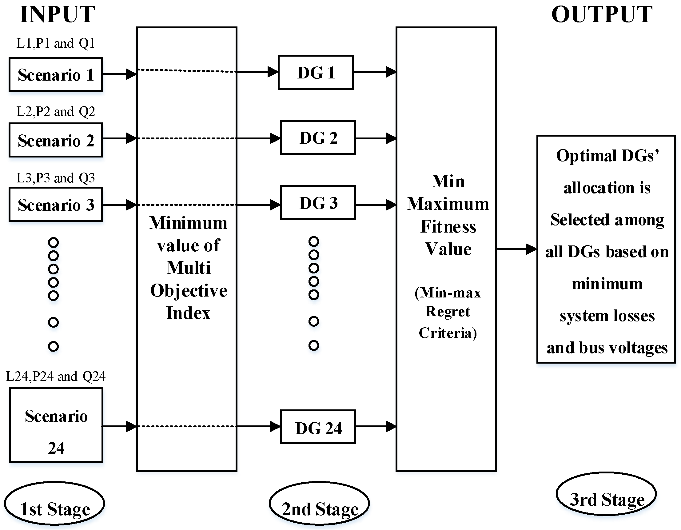
Figure 1. System Block Diagram.
Energies 15 03701 g001
Figure 2. Flow Chart of BRO Algorithm.
Energies 15 03701 g002
Figure 3. Flow Chart of APSO Algorithm.
Energies 15 03701 g003
Figure 4. Flow Chart of GA.
Energies 15 03701 g004
Figure 5. Methodology.
Energies 15 03701 g005
Figure 6. CIGRE MV Benchmark Model.
Energies 15 03701 g006
Figure 7. Power Curve: (a) solar; (b) wind.
Energies 15 03701 g007
Figure 8. MO Values.
Energies 15 03701 g008
Figure 9. Convergence Curve.
Energies 15 03701 g009
Figure 10. Active Power Losses.
Energies 15 03701 g010
Figure 11. Active power losses of (a) Branch 1, (b) Branch 2, (c) Branch 3, (d) Branch 4, (e) Branch 5, (f) Branch 6, (g) Branch 7, (h) Branch 8, (i) Branch 9, (j) Branch 10, (k) Branch 11, (l) Branch 12, (m) Branch 13, (n) Branch 14, and (o) Branch 15.
Energies 15 03701 g011aEnergies 15 03701 g011bEnergies 15 03701 g011c
Figure 12. Reactive Power Losses.
Energies 15 03701 g012
Figure 13. Reactive power losses of (a) Branch 1, (b) Branch 2, (c) Branch 3, (d) Branch 4, (e) Branch 5, (f) Branch 6, (g) Branch 7, (h) Branch 8, (i) Branch 9, (j) Branch 10, (k) Branch 11, (l) Branch 12, (m) Branch 13, (n) Branch 14, and (o) Branch 15.
Energies 15 03701 g013aEnergies 15 03701 g013bEnergies 15 03701 g013c
Figure 14. All Bus Voltage Profiles (Before DG).
Energies 15 03701 g014
Figure 15. Voltage profiles of (a) Bus 3, (b) Bus 4, (c) Bus 5, (d) Bus 6, (e) Bus 7, (f) Bus 8, (g) Bus 9, (h) Bus 10, (i) Bus 11, (j) Bus 12, (k) Bus 13, and (l) Bus 14.
Energies 15 03701 g015aEnergies 15 03701 g015b
Table 1. Indices.
Table 1. Indices.
IndicesW
API0.5
RPI0.25
VD0.25
Table 2. Parameters of Algorithms.
ParametersBROAPSOGA
No. of Iterations100100100
Population Size100100100
Size Range of DGs (kW and kvar)10~50010~50010~500
Table 3. Optimal DG allocations at each scenario.
ScenariosAPSOGABRO
DG
Locations
DG
Sizes
DG
Locations
DG
Sizes
DG
Locations
DG
Sizes
11, 2, 12171.30, 10, 43.8712, 1, 251.35, 214.26, 14.732, 1, 1215.51, 162.58, 40.43
21, 12, 2166.89, 24.50, 1012, 1, 224.37, 205.93, 57.492, 1, 1214.78, 168.37, 25.66
32, 1, 1210, 158.81, 19.6012, 1, 265.80, 413.49, 50.082, 1, 1218.66, 174.74, 23.16
413, 1, 1210, 166.26, 24.472, 12, 110.14, 28.47, 146.751, 2, 8135.25, 43.98, 11.57
51, 12, 8194.65, 41.99, 102, 1, 1232.49, 173.65, 39.4912, 1, 240.54, 169.10, 21.74
612, 1, 281.44, 172.96, 1012, 1, 1361.33, 198.32, 26.4012, 8, 184.15, 12.57, 240.66
71, 6, 12200.19, 10, 116.281, 12, 13235.07, 99.55, 33.701, 12, 13216.04, 105.89, 24.47
81, 2, 12178.15, 10, 129.1912, 2, 1127.44, 55.41, 201.7113, 1, 1216.55, 179.16, 114.01
91, 2, 12177.58, 10, 127.212, 1, 1242.21, 238.37, 136.202, 1, 1251.20, 202.74, 127.79
1012, 1, 8131.33, 196.0, 1012, 13, 1126.07, 13.87, 205.3112, 2, 1136.29, 31.52, 207.41
1112, 6, 1111.92, 10, 199.0713, 12, 121.92, 97.80, 194.212, 1, 1221.21, 203.31, 116.99
1212, 13, 1127.28, 10, 185.682, 12, 153.44, 131.12, 203.131, 12, 2227.45, 136.17, 77.57
131, 2, 12178.40, 10, 124.3712, 1, 2126.32, 202.01, 21.5014, 1, 1211.28, 187.81, 113.93
1413, 1, 1210, 182.84, 106.1612, 2, 1109.70, 35.14, 186.681, 8, 12186.22, 13.79, 104.92
152, 1, 1210, 174.06, 103.362, 12, 172.13, 98.57, 204.191, 2, 12208.96, 96.62, 96.12
162, 1, 1210, 172.15, 95.4212, 2, 184.97, 135.51, 219.1712, 1, 289.80, 206.86, 60.59
171, 2, 12177.77, 109.28, 101, 2, 12190.36, 33.58, 107.721, 12, 2184.21, 99.20, 90.54
1812, 1, 2127.56, 18.48, 1013, 12, 129.45, 107.84, 214.1713, 1, 1229.10, 249.02, 115.30
1912, 8, 1139.92, 10, 201.151, 13, 12243.72, 55.93, 105.2412, 13, 1134.70, 15.65, 208.25
208, 12, 110, 124.32, 201.262, 1, 1210, 183.09, 126.881, 2, 12190.74, 49.36, 122.56
218, 12, 110, 10.86, 198.242, 1, 1210.02, 176.03, 104.472, 12, 144.88, 98.21, 152.83
222, 12, 110, 87.56, 177.391, 2, 12173.30, 10, 87.158, 1, 1211.12, 207.20, 86.28
238, 12, 110, 59.63, 187.212, 1, 1236.33, 213.13, 66.798, 12, 111.64, 57.52, 180.04
248, 12, 110, 35.87, 187.8112, 1, 223.07, 89.04, 19.912, 1, 1254.13, 200.46, 35.66
Table 4. Optimal DG sizes and locations for all scenarios.
AlgorithmsDG 1 LocationDG 2 LocationDG 3 LocationDG 1 Size (×1000)DG 2 Size (×1000)DG 3 Size (×1000)
GA1122181.11962.56810.504
APSO1122208.64370.11733.410
BRO1122200.22169.16829.152
Table 5. Optimal MO Values.
ScenariosBROGAAPSOScenariosBROGAAPSO
10.50270.51430.5027130.09730.10060.1070
20.56430.56430.5642140.12070.12450.1207
30.65600.55800.5580150.14330.14740.1567
40.56420.56420.5642160.16830.16820.6334
50.49840.48690.7834170.14160.13320.1292
60.23260.23260.2537180.09340.09330.1027
70.11180.11180.1083190.07340.07340.0762
80.08930.09240.0924200.09530.09530.1048
90.10150.09220.0954210.14570.14140.1456
100.08220.08220.1991220.20600.21160.2116
110.12070.11700.1170230.36590.35700.3570
120.09200.08340.0920240.57880.53180.5318
Table 6. Summary of Results.
AlgorithmBefore DGGAAPSOProposed BRO
Maximum Fitness---6.396.696.48
V min (pu)0.46220.73260.70560.7261
V max (pu)1.09581.22691.21591.2250
P loss (%) Red055.8853.0355.69
Q loss (%) Red047.7746.2348.47
Min Line Losses (P, Q)
(kW, kvar)
0.346432,
0.498524
1.392466,
1.992093
1.45,
2.074574
1.384796,
1.98112
Max Line Losses (P, Q)
(kW, kvar)
14,569.43,
16,907.7
6619.197,
9493.322
7199.756,
10,325.97
6465.435,
9272.794
Average Active Power loss
(All Scenarios)
26,617.9311,743.2312,502.7311,794.14
Average Reactive Power loss
(All Scenarios)
26,805.4913,999.7514,412.6513,813.91
Active Energy loss
(All Scenarios)
(kWh)
638,830.3281,838300,065.4283,059.7
Reactive Energy
Losses
(All Scenarios)
(kvarh)
643,331.89335,994.1345,903.6331,534.010
Table 7. Average Active Power Losses along Branches (kW).
AlgorithmsBranch
1
Branch
2
Branch
3
Branch
4
Branch
5
Branch
6
Branch
7
Branch
8
Branch
9
Branch
10
Branch
11
Branch
12
Branch
13
Branch
14
Branch
15
Before DG789.4159.94678.550.19.7442.71.7473.2882.714.459.03214.78124.12405.85312.2
GA320.1249.12724.1172.49.3437.61.5488.21381.568.8239.81697.02074.6535.31343.9
APSO163.4230.02845.2158.89.1431.01.6500.71337.960.5212.81792.62489.7642.71626.6
Proposed BRO263.2235.12671.2170.29.2434.31.5495.61374.367.0234.51661.62194.6584.01398.0
Table 8. Average Reactive Power Losses of Branches (kvar).
AlgorithmsBranch
1
Branch
2
Branch
3
Branch
4
Branch
5
Branch
6
Branch
7
Branch
8
Branch
9
Branch
10
Branch
11
Branch
12
Branch
13
Branch
14
Branch
15
Before DG1129.3228.36709.971.613.9634.62.4674.21268.820.785.14595.25829.01730.13812.3
GA458.0355.63906.9246.313.2627.22.2695.81985.999.0345.92425.81488.5385.0964.4
APSO233.7328.44080.6226.913.1617.82.3713.61923.287.0307.12562.41786.4462.21167.3
Proposed BRO376.5335.73831.0243.113.1622.52.2706.31975.596.4338.22375.11574.6420.01003.3
Table 9. Average Bus Voltages.
AlgorithmsBus
1
Bus
2
Bus
3
Bus
4
Bus
5
Bus
6
Bus
7
Bus
8
Bus
9
Bus
10
Bus
11
Bus
12
Bus
13
Bus
14
Before DG1.03001.03001.01380.93650.94440.93700.91680.91370.89060.94030.93890.93020.66540.7762
GA1.03001.03001.07971.04471.06261.05541.03531.03221.00881.07121.06291.04880.93580.9735
APSO1.03001.03001.07681.03591.05301.04581.02591.02270.99901.06051.05271.03910.90880.9545
Proposed BRO1.03001.03001.07701.04341.06121.05391.03401.03091.00731.06961.06131.04730.92930.9699
Publisher’s Note: MDPI stays neutral with regard to jurisdictional claims in published maps and institutional affiliations.