Abstract
A battery–supercapacitor hybrid energy storage system is investigated as a solution to reduce the high-power delivery stress on the battery. An optimally-sized system can further enhance the storage and cost efficiency. This paper discusses several possible problems in the sizing of a battery–supercapacitor hybrid energy storage system for practical applications. A sizing method that utilises data collected from a fully active embedded control hybrid energy system is proposed. The feasibility of the method is then tested on three load profiles that represent the load demand of inter- and intra-applications with a battery–supercapacitor hybrid energy storage system. The result is compared to a battery-only single energy storage system. The results verified that the number of batteries required in the hybrid energy storage system is reduced by at least 50% compared to the battery-only single energy storage system.
1. Introduction
Battery and supercapacitor systems are currently the most promising portable energy storage solutions. The capability of each is synergised when combined in a battery–supercapacitor hybrid energy storage system (HESS). The storage and cost efficiency can be further enhanced when they are optimally sized for practical purposes. The hybridisation reduces the battery size, increases the battery life span, improves the power efficiency, and thus reduces the initial and recurring cost of the battery [1,2]. The combination of a battery and supercapacitor, thus, has been studied for many applications [3,4,5]. Several types of topologies have been proposed for the integration of battery–supercapacitor pairs, and experiments are being carried out to verify the feasibility of the various topologies [6,7]. The topologies are passive, semi-active, and fully active [1,2,6]. The difference between these three topologies is the controllability of the system, with the fully active topology having the most controllability. The control strategies for a semi-active HESS and a fully active HESS have been reported, targeting different desired outputs from the hybridisation [8,9,10]. Two types of fully active HESS topology will be discussed in the current work, and the sizing strategy will be built based on a fully active HESS topology.
The supercapacitor is designed to take the entire high-power load when there is a surge in power demand, and the battery is designed to support the high energy demand of the load. However, in a practical application, such a condition can only be obtained if there is sufficient energy from both the battery and supercapacitor. Thus, when the state-of-charge (SOC) of each energy storage device falls below its usable power spectrum, the HESS can no longer operate in an ideal condition. To solve the problem, the sizing of energy storage based on the individual user’s power and energy demand must be considered.
The general approach to sizing a HESS is based on the average load profile of the selected application [11]. Based on this method, the sizing of electric vehicles (EV), photovoltaics (PV), and microgrids [12,13] have been studied. In other work, a modified particle swarm optimisation (PSO) algorithm was adopted to optimise the sizing of a battery-only, supercapacitor-only, and a battery–supercapacitor hybrid configuration [14,15]. A PSO algorithm takes in different parameters such as the component data, vehicle parameters, and drive cycles as input for the optimal sizing of the energy storage. In the study, the sizing method considered many aspects of the vehicle’s condition for an electric city bus application with a general urban drive cycle. A filter-based approach with an optimal noncausal energy management method was used to minimise the installation and running costs of an EV [16]. A multi-objective optimisation algorithm was proposed to minimise the energy storage cost by prolonging the battery life of the EV [12]. This sizing method adopted a state-of-health (SOH) model to maximise the energy storage operation life span. In another study, a sizing method using pinch analysis and design space for a PV-based application was proposed [17]. The proposed method considers the storage time-frame of each energy storage device, with a fuel cell for long-term storage, batteries for medium-term storage, and supercapacitor for short-term storage. In the sizing of a HESS for a forklift application, different operating conditions of a forklift were considered to optimise the sizing of energy storage based on the forklift’s efficiency, volume, and mass [18]. A sizing strategy considering a typical forklift’s general load cycle was also introduced in the study. The same author also used different standardised driving cycles of vehicles (NEDC, ARTEMIS, FTP-75 and WLTP) to size the energy storage [11].
A specific user needing energy storage with different demands can be solved by coupling the real-time data collected by an energy management controller. However, a semi-active HESS faces limited flexibility due to the limited control over the energy storage device compared to a fully active HESS. Therefore, to overcome the problem of sizing that is based on the overall drive cycle of an electric vehicle (EV), a sizing model for a semi-active HESS topology that couples with a real-time energy management controller was developed [19]. The sizing of a HESS based on real-time data provides better accuracy. This ensures minimal energy storage capacity wastage and at the same time is capable of ensuring sufficient power delivery.
The sizing of the battery–supercapacitor in a HESS is essential to promote the maximum interest of the battery–supercapacitor hybridisation. The current work proposes a sizing strategy for a fully active HESS that considers the characteristics of different users and the future uncertain changes in the load characteristics. The strategy is designed and tested based on the consideration of the following: battery–supercapacitor HESS topology, sizing of energy storage, and HESS application.
1.1. Battery–Supercapacitor HESS Topology
The battery–supercapacitor HESS topologies are categorised into: passive topology, semi-active topology, and fully active topology [2,6]. The difference between these three topologies is the controllability of these topologies. The passive topology relies entirely on the physics of the battery–supercapacitor connection and has no control over the battery–supercapacitor’s power flow. The semi-active HESS topology includes a control converter for each energy storage device. Finally, both of the energy storage devices are controlled by a converter in a fully active HESS topology.
In an ideal condition for a battery–supercapacitor HESS system, the supercapacitor should supply all high-power conditions due to its high-power density characteristic. The passive and semi-active HESS topologies have minimal control over the power flow of the HESS and cannot satisfy this condition. Hence, only the fully active topology can assert sufficient control over the entire power flow of each energy storage device to achieve this ideal condition. One of the examples is a novel fully active HESS design that can be used to replace the DC–DC converter, while maintaining the controllability of the system [12]. This is done by using the supercapacitor to support the high power demand of the load, and the battery is completely switched off during the high-power condition. A fully active HESS will be used in the current work.
1.2. Sizing of Energy Storage
In energy storage sizing, undersized energy storage may affect the overall available operation time of the application, which will result in the subpar performance of the system. Hence, oversizing components is a common practice in most electrical designs. The sizing of a single energy storage system (SESS) is more straightforward. The sizing is carried out based on the average amount of energy needed by the application. However, in a HESS implementation, a multiple energy storage device must be sized accurately to cater for different load demands. If either energy storage device is undersized, the interest of the battery–supercapacitor HESS will be lost, and the system may operate as a SESS instead of a HESS.
The sizing of a battery–supercapacitor HESS can be further improved by reducing the oversized energy storage device and utilising it to improve the other energy storage device [20]. In a practical application, different users have different demands. Some users may have a higher power demand and lower energy demand, while others may have a lower power and higher energy demand.
1.3. HESS Application
There are three types of possible scenarios that may contribute to sizing inaccuracy in a practical implementation of a fully active HESS, which are:
- Inter-application load demand difference,
- Intra-application load demand difference,
- Uncertain changes in future load demand.
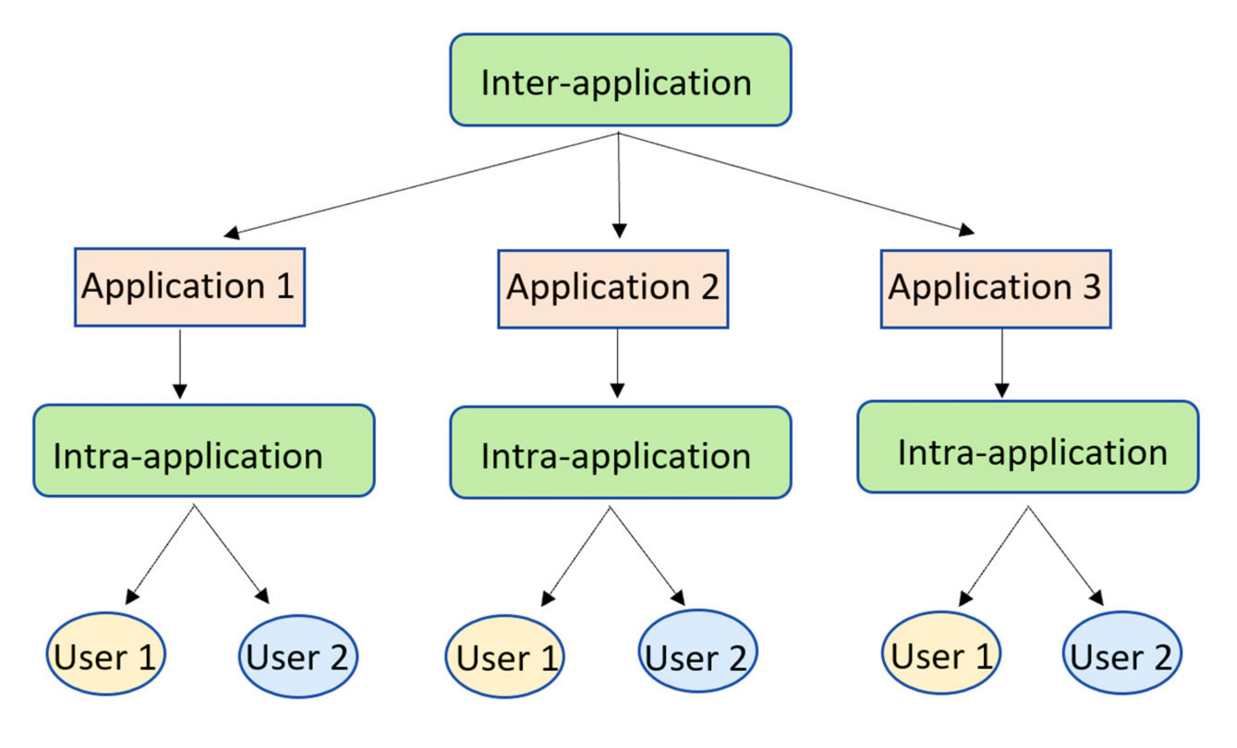
Inter-application refers to two different types of applications. Examples of inter-application are electric buses, residential electrification, industrial electrification, and mobile medical centres. These energy storage systems are different and require different designs to cater to their unique requirements. On the other hand, intra-application represents the same application, but with different load characteristics. Examples of intra-applications are two different electric buses travelling on a different route, different electric vehicles operating in different areas, and different mobile medical centres serving different populations. The inter- and intra-application relationship is shown in Figure 1.
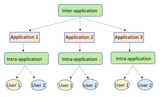
Figure 1.
Inter-application and intra-application relationship.
In order to cater for the load demand difference in a practical environment, the sizing of a HESS based on an actual load profile is preferred. In the current work, an urban electric bus application and a mobile vaccination centre application are used to illustrate the different load characteristics of inter- and intra-applications.
2. Materials and Methods
2.1. Battery and Supercapacitor
The specifications of the lithium polymer battery and the supercapacitors used in this work are shown in Table 1 and Table 2.

Table 1.
Specification of lithium polymer battery.
Table 2.
Specification of supercapacitor.
2.2. Load Sharing Method of the Fully Active Battery–Supercapacitor HESS
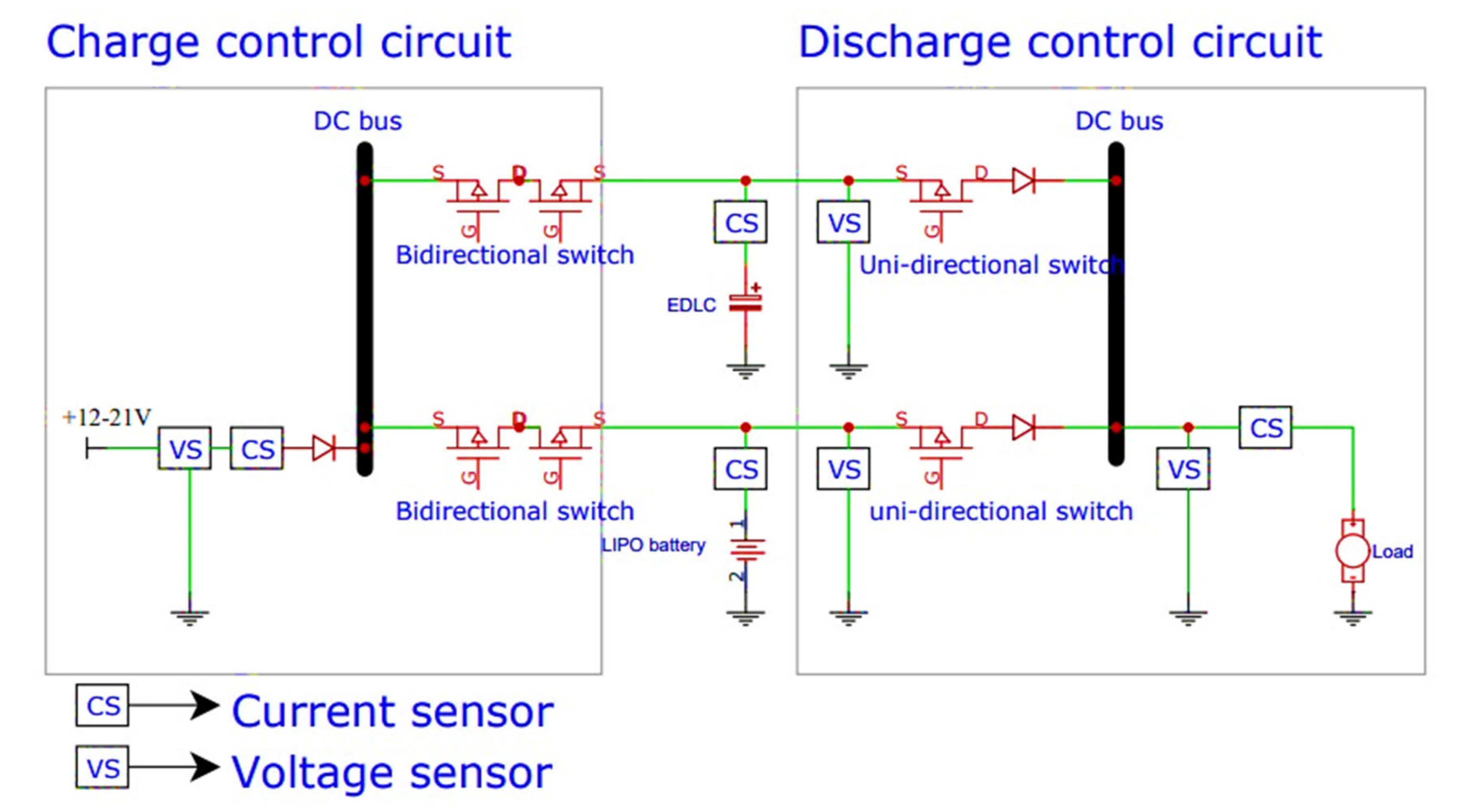
Based on the algorithm in the embedded system, energy will be drawn from the supercapacitor if it is above the threshold current (Ith). This state is called the “high power condition”. If the current is below the threshold value, the energy will be drawn from the battery. This state is referred to as the “nominal power condition”. The schematic of the fully active HESS system is shown in Figure 2.
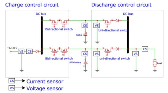
Figure 2.
Schematic of fully active battery–supercapacitor HESS.
2.3. Sizing Strategy
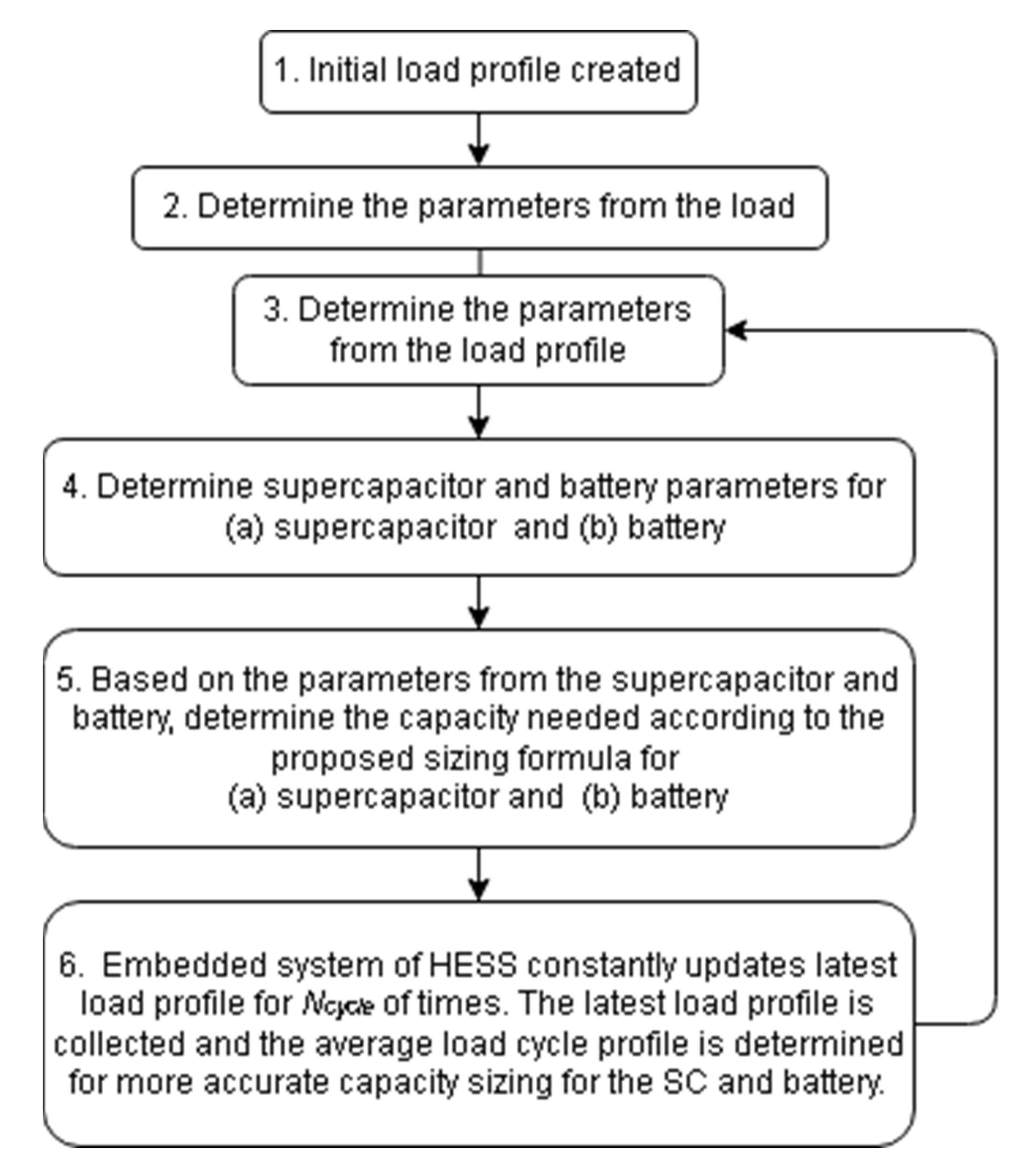
Figure 3 shows the flowchart of the proposed sizing strategy. The sizing strategy operates so that the sizing is performed constantly to adapt to the inter- and intra-application and future changes to the load characteristics. This constant looping method can size the HESS energy storage based on the load profiles obtained by the fully active HESS embedded control system. Thus, using the latest load data from several iterations collected by the embedded control system, each energy storage device can be optimally sized. The proposed capacity sizing strategy assumes that the HESS will not be charged while discharging.

Figure 3.
Flowchart for the proposed sizing strategy.
The details of each step are as follows:
- Step 1: Initial load profile
- Step 2: Parameters from the load
- -
- Rated load voltage, Vload (fixed value),
- -
- Rated load power, Pload (fixed value),
- -
- Max current, Imax (fixed value) is the maximum current drawn by the load Equation (1).
- -
- Threshold current, Ith (fixed value) is the battery maximum current rating.
- Step 3: Parameters from the load profile
An average number of load profile cycles (from the first charge to next charge) should be determined in order to obtain a more accurate estimation of the load characteristics for sizing. This is because the load cycle cannot be determined solely based on the latest load cycle. The number of iterations used for estimation, Ncycle value, is manually set by the user based on the application requirements.
The total discharge time, ttotal, is the total time the HESS spends in the discharging operation, which is the last charged time to the next charge time, as given by Equation (2).
The time above threshold current is obtained when the load demands a high power supply and the time where the supercapacitor is used to supply power to the load. The average discharge time above the threshold current, thigh, is given by Equation (3):
The time below threshold current is obtained when the load demands a nominal power supply and when the battery is used to supply power to the load. The total average discharge time below the threshold current, tlow, is given by Equation (4):
- Step 4 (a) (supercapacitor): supercapacitor sizing parameter
The following parameters are obtained from the supercapacitor model:
- The capacity of a single supercapacitor cell/capacitance in Farad (F), CSCS.
- The voltage of a single supercapacitor cell, VSCS.
The voltage of the supercapacitor can be increased by connecting multiple supercapacitors in series. Such a connection is used to create a voltage terminal that is capable of supporting the rated load voltage. The voltage of the supercapacitors connected in series is given by Equation (5):
The voltage of the supercapacitor remains the same across the terminal when they are connected in parallel. The voltage of the supercapacitors connected in parallel is given by Equation (6):
When the supercapacitor is connected in series, the capacitance of the supercapacitor behaves as a resistor connected in parallel. The capacitance of the supercapacitor will be reduced when the supercapacitors are connected in series, CSCS. The capacitance of the supercapacitors connected in series is given by Equation (7):
However, the total capacitance of the supercapacitor can be increased by connecting more supercapacitors in parallel, CSCP. The capacitance for supercapacitors connected in parallel is given by Equation (8):
Based on the voltage of a single supercapacitor, VSCS, the number of supercapacitors in series, NSCS, can be determined from Equation (9):
The number of supercapacitors connected in series, NSCS, will be oversized by a variable p and is always rounded up. This is to prevent overvoltage across the supercapacitors during charging. Hence, the supercapacitors should be slightly oversized by one cell to prevent overvoltage damage.
NSCS, the number of supercapacitors in series, and CSCS(total), the total capacitance of supercapacitors in parallel, can be determined from Equation (8).
The discharge time of a supercapacitor at max current, tSC, is obtained from the discharge curve of the supercapacitor. Assuming all of the high power conditions of the load cycle are discharged at the maximum current, Imax, the discharge time of the supercapacitor at the maximum current is used to determine the duration of a single supercapacitor cell, CSCS (total), that can be discharged at the maximum current. The discharge time of the supercapacitor at the maximum current, tSC, is given by Equation (10):
The maximum voltage of the supercapacitor, VSC max (fixed value), is determined by the nominal voltage of the load, Vload. Since Vload is a nominal value for the load, the input voltage to the load can be slightly higher for a longer discharge time.
The minimum voltage of a supercapacitor, VSC min (fixed value), is determined by the nominal voltage of the load, Vload. Since the Vload is a nominal value for the load, the input voltage to the load can be slightly lower for a longer discharge time.
When the capacitance of the supercapacitor is doubled, the discharge time is also doubled. The total capacitance of the supercapacitor can be increased by connecting more supercapacitors in parallel, as shown in Equation (8).
- Step 5 (a) (supercapacitor): supercapacitor sizing formula
Hence, from the discharge time of the supercapacitor at maximum current, tSC, the total number of supercapacitors connected in parallel, NSCP, that will deliver all of the high-power demand of the load cycle can be determined by Equation (11):
The number of supercapacitors connected in parallel is added by variable p to oversize the supercapacitor to cater for uncertain changes and contingency purposes.
The total capacitance of the supercapacitor, CSCP, that will deliver all of the high-power demand of the load cycle can be determined by Equation (12):
- Step 4 (b) (battery): battery sizing parameter
The following parameters are obtained from the battery:
- Capacity of single cell battery in Amp-hour (Ah), CBS.
- Voltage of single cell battery, VBS.
The voltage of the battery can be increased by connecting multiple cells in series. Such a connection can be constructed to achieve a terminal voltage meeting the load rating. The voltage of the battery connected in series is given by Equation (13):
The voltage of the battery remains the same across the terminal when the battery is connected in parallel, given by Equation (14):
Unlike the supercapacitor, the capacity of the battery remains the same in serial connection, given by Equation (15):
The capacity of the battery can be increased by connecting the batteries in parallel. The capacity of the battery can be increased for a longer discharging time under the load. The capacity of the battery connected in parallel is given by Equation (16):
To size the battery, several parameters must first be determined, which include the voltage and capacity of the battery. The basic battery specifications can be used for the overall sizing of a battery. However, unlike supercapacitors, there are different types of battery that require different considerations, including the voltage operating region and the maximum discharge current. In this paper, a lithium polymer battery (LiPo) is used.
From the voltage of a single battery, VBS, the number of batteries connected in series, NBS, can be determined by Equation (17):
Compared to supercapacitors, batteries do not need to be oversized in series, as long as the total voltage of the batteries matches or exceeds the rated voltage. This is because the operating range of the battery is very narrow, unlike the supercapacitor. The battery also needs a higher voltage across its terminals for charging. Hence, based on these two reasons, the serial sizing of the battery does not need to be oversized and can be rounded down.
The capacity of the battery is measured in amp hour (Ah). The discharge time of one battery cell at the threshold current, tbatt, can be derived from the Ah unit.
- Step 5 (b) (battery): Battery sizing formula
Hence, from the discharge time of the battery at the threshold current, tbatt, the total number of battery cells in parallel, NBP, for the battery to deliver all of the nominal power demand of the load cycle can be determined from Equation (19):
The number of battery cells in parallel is increased by variable r to slightly oversize the battery capacity to cater for uncertain changes and contingency purposes. However, the oversizing can be adapted according to the application requirements by changing the value of r.
The total capacity of the battery in parallel, CBP, for the battery to deliver all of the nominal power demand of the load cycle can be determined from Equation (20):
3. Results and Discussion
3.1. Battery and Supercapacitor Discharge Time
Table 3 shows the calculated and experimental discharge times of the battery and supercapacitor. The calculated values are obtained using Equation (10) for the battery and Equation (17) for the supercapacitors. The experimental results are obtained with an electronic load. The discharge is measured on six units of supercapacitors or three units of LiPo batteries connected in series. Both the supercapacitor and the LiPo battery are discharged from 12.6 V to 10.5 V. For the LiPo battery, when the discharge current is 0.3 A, the discharged time obtained from the experiment is 14% lower than the calculated value. At 0.7 A, the experimental value is 9% higher than the calculated value. At 1 A, the experimental value is 40% higher than the calculated value. The large difference is because in an actual discharge, the electronic load cannot maintain a constant drain when the voltage of the LiPo battery dips below 11.55 V. For supercapacitors, the discharge time obtained from the experiment is slightly shorter than the calculated values by 4% at 1 A, 6% at 0.7 A, and 14% at 1 A. The comparison shows that the calculated values can serve as a guide, but often deviate from the values obtained from an actual energy storage device. The difference is high, especially for the case of the battery. Thus, in order to obtain an accurate sizing of an energy storage system, the values from experiment are the most appropriate.
Table 3.
Discharge time of LiPo battery and supercapacitor.
3.2. Load Profile from the Battery–Supercapacitor HESS Embedded Control System
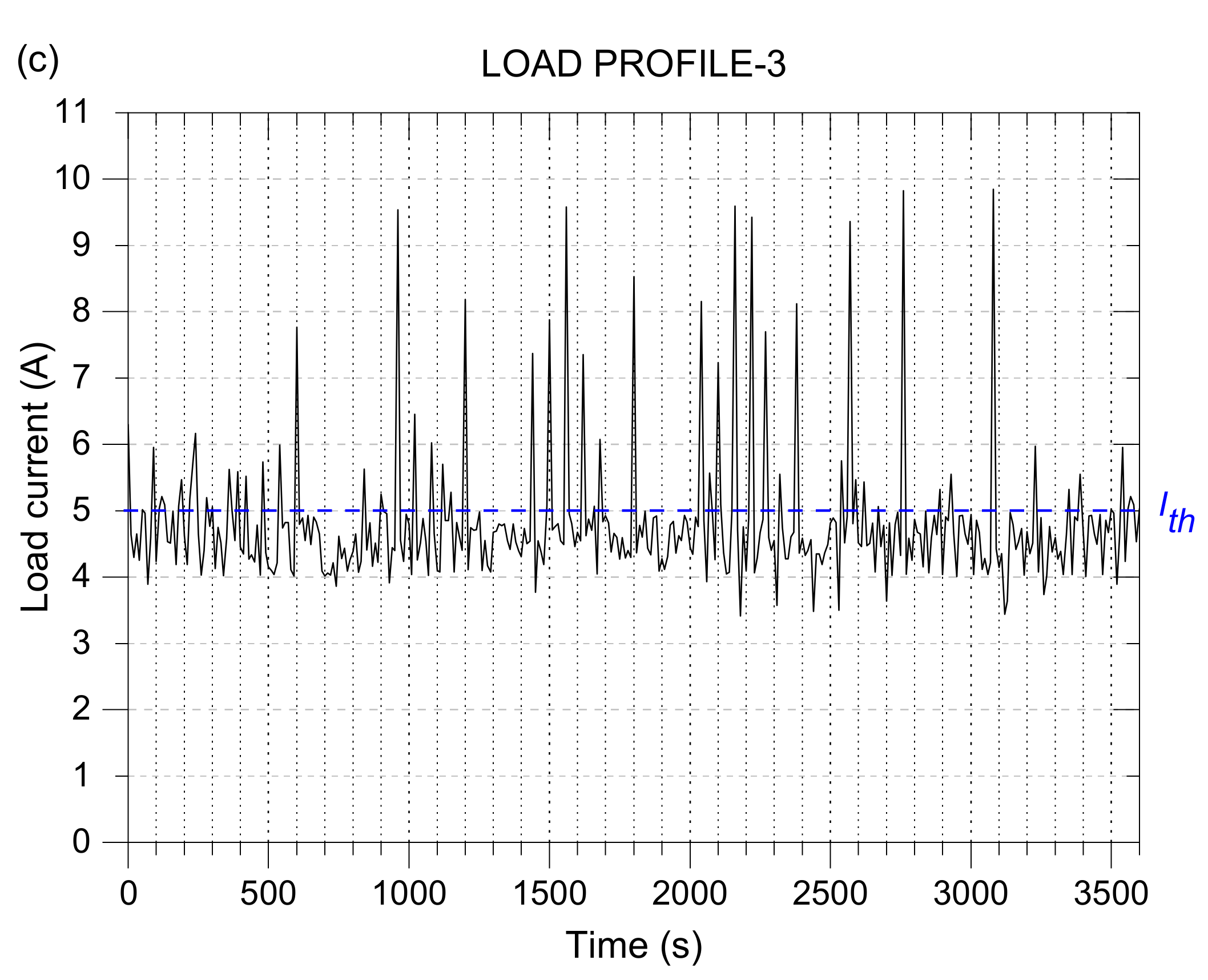
Three load profiles representing three different load scenarios are generated to represent inter- and intra-application. Load profile 1 represents an urban electric bus, where the load operates more in the high power region. Load profile 2 represents an identical urban electric bus, but operates less in the high power region and more in the nominal power region. These two load profiles are used to show the difference in load characteristics of an intra-application scenario. The third scenario, load profile 3, represents a mobile vaccination centre storage unit. Load profile 3 operates mainly in the nominal power region with minimal high power region operation.
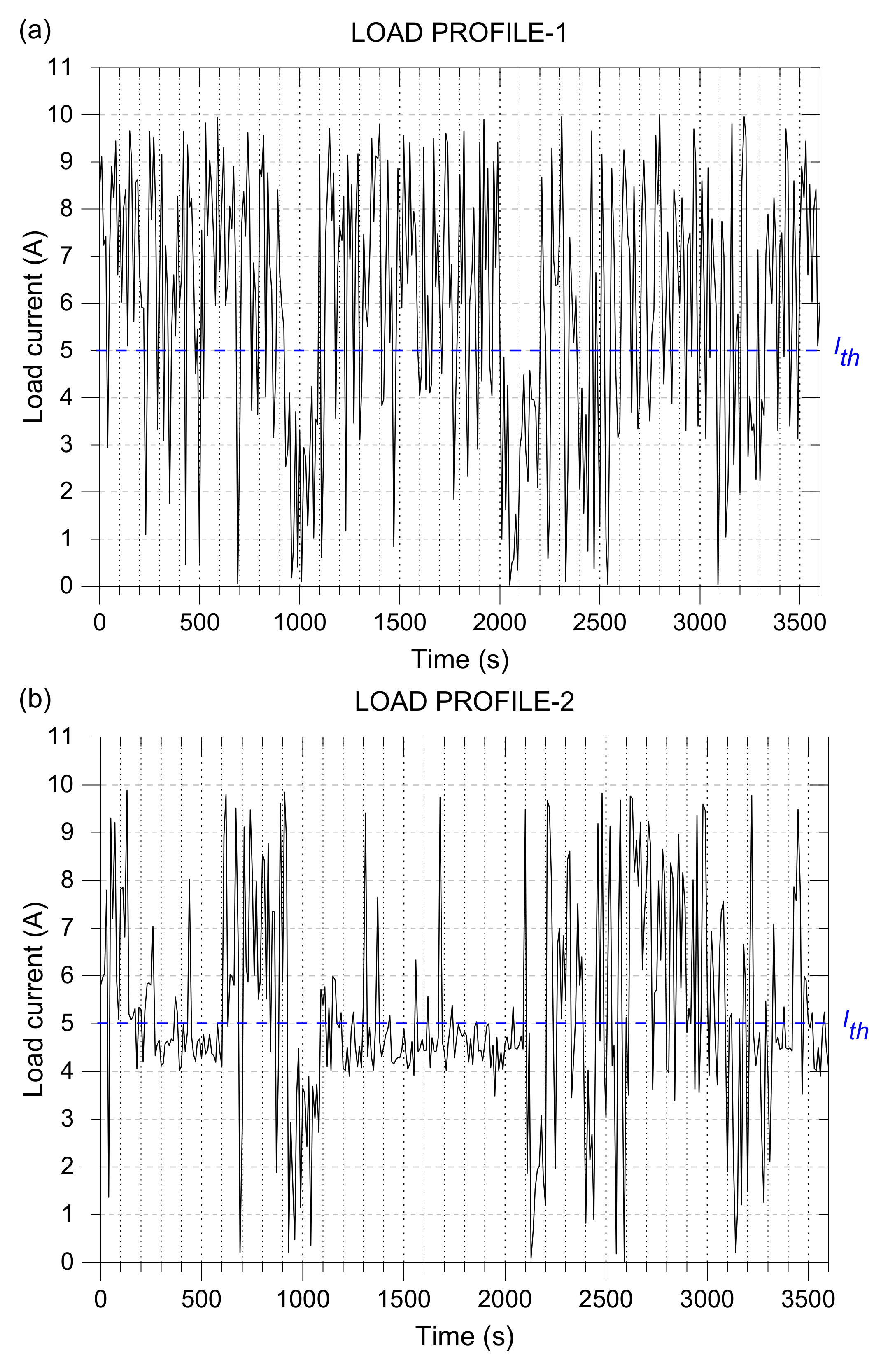
A resistive load of 12 V, 120 W, is used. A PWM controller is used to control the current drawn by the load. Random fluctuations are included in the load profiles. The randomised PWM signal is sent from the embedded system to the PWM controller to model the load current. The current through the load is monitored by a sensor and recorded for 1 h. The three load profiles are shown in Figure 4.
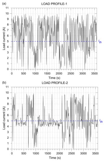
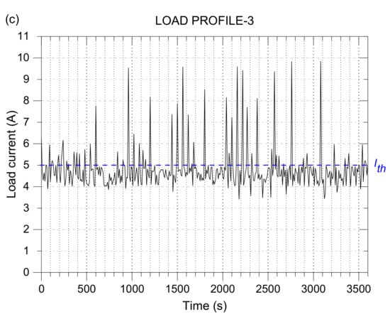
Figure 4.
(a) Load profile 1 represents an urban electric bus (high power operation). (b) Load profile 2 represents an urban electric bus (high and nominal power operation). (c) Load profile 3 represents a mobile vaccination centre storage unit (nominal power region).
The random power fluctuations above and below the threshold current (5 A) signify the uncertain changes in load power in a practical setting. The power above the threshold is considered a high-power operation, in which the supercapacitor will be used as the main power supply. The power below the threshold is considered a nominal power operation, where the battery will be used as the main supply. The one-hour load profile is taken as the total operation time (from the first charge to the next charge) of the application. Load profile 1 represents an urban electric bus that operates more in the high power region because of the higher frequency of stops along its route. Load profile 2 represents an identical urban electric bus that travels for the same distance, but with fewer stops than the bus in profile 1. Therefore, 57% of the power drain during its operation is in the nominal power region. Load profile 3 represents an HESS powering the storage unit of a mobile vaccination centre. In this scenario, 84% of its operations are in the nominal power region. A summary of the load profile characteristics is shown in Table 4.
Table 4.
Load profile from the active HESS.
3.3. Capacity Sizing Parameters for the Load Profiles
The sizing of the HESS is performed for the three load profiles based on the proposed strategy in Figure 2.
3.3.1. Parameters from the Load
A resistive load of 12 V, 120 W, is used and the maximum current for the LiPo battery is set to 5 A ().
3.3.2. Parameters from Supercapacitor and Battery
The battery is sized with three units of LiPo battery connected in series with a working voltage range of 10.5 V to 12.6 V. Table 5 shows the LiPo battery sizing specifications. Sizing for the supercapacitor is carried out on six units of supercapacitors connected in series. The specifications of the supercapacitor are shown in Table 6. Both the LiPo and the supercapacitor are subjected to three identical load profiles.
Table 5.
Parameters for LiPo battery.
Table 6.
Parameters for supercapacitor.
3.4. Capacity Sizing Result of Battery–Supercapacitors HESS
The parameters of the supercapacitor are used in the sizing from Equations (11) and (12). The value of the oversized variables p and q are selected as 1. The parameters from the battery are placed into the battery sizing formulas in Equations (19) and (20). The value of the oversize variable r is selected as 1.
Table 7 shows the result of the sizing of the battery–supercapacitor HESS. Load profiles 1 and 2 are identical in application, but different in terms of the load profile. The number of battery cells in parallel, NBP, can be reduced for load profile 1 compared to load profile 2. If the HESS is sized according to the load profile, the number of required battery cells in parallel, NBP, is different. However, if the HESS is sized based on the application, the number of batteries in load profile 1 is not sufficient to supply the energy required for load profile 2. The supercapacitor for load profile 1 will also be oversized and wasted if used in load profile 2.
Table 7.
Sizing results of battery–supercapacitor HESS.
Load profile 3 represents an application that operates in the low power region for about 84.45% of the time. The total number of supercapacitors and battery cells required is lower than for the other two load profiles. The number of supercapacitor cells used in parallel, NSCP, is almost half of those used in load profile 2, while the number of battery cells in parallel, NBP remains the same. Hence, the battery–supercapacitor HESS did not significantly improve the system operating in the nominal power region, in terms of the number of battery cells. However, in the long run, the supercapacitor may reduce the battery charge–discharge cycle.
The same load profiles are used to size a battery-only SESS, with a maximum current rating of 10 A. The maximum current of the load profile is used to calculate the capacity and the battery cells in parallel to power the load for the entire operation. In order to achieve this, the threshold current used to size the battery in Equation (18) is replaced by the maximum current, and Equations (19) and (20) are used. The results for the battery-only SESS is shown in Table 8.
Table 8.
Sizing results of the battery-only SESS.
The results verified that the number of batteries for the HESS is significantly reduced compared to the battery-only SESS. It is noted that the HESS has been oversized by 1, therefore the probability of the battery over-discharging and supercapacitor over-voltage protection is minimised. SESS is also oversized by 1. The safety during operation is taken into account. Due to the lower lifecycle of the battery, the battery replacement cost may increase significantly when more batteries are used. The comparison shows that the battery–supercapacitor hybridisation can reduce the total number of batteries by at least 50%. Due to the reduced number of batteries used in an HESS, the battery replacement cost over the long run can also be reduced significantly.
4. Conclusions
A sizing strategy that considers individual load characteristics by utilising the load data collected from the embedded control fully active battery–supercapacitor HESS is designed and tested in this work. The proposed sizing strategy is implemented to size the energy storage based on each of the three load profiles that represent inter- and intra-applications (1. Urban electric bus that operates more in the high power region. 2. Urban electric bus that operates less in the high power region and more in the nominal power region. 3. Mobile vaccination centre that operates predominantly in the nominal power region). The same sizing strategy is applied to the battery-only SESS for comparison. The results verify that the number of batteries needed in a battery–supercapacitor HESS is reduced by at least 50% compared to a battery-only SESS. The proposed strategy is flexible and can be extended to other applications for all types of energy storage devices based on the parameters obtained experimentally in a hybrid energy storage system. However, the proposed sizing strategy requires continuous resizing between the supercapacitor and battery, as the load usage characteristics may change over time. To solve this problem, an efficient energy storage swapping technology could be useful in such a scenario. Further studies into a battery–supercapacitor HESS swapping method are recommended.
Author Contributions
Conceptualization, N.L., C.H.N., S.S.Y. and K.K.T.; methodology, N.L., C.H.N. and K.K.T.; software, N.L.; validation, N.L. and C.H.N.; formal analysis, N.L., C.H.N. and K.K.T.; investigation, N.L., C.H.N. and K.K.T.; resources, A.K.B.M.A. and A.H.Y.; data curation, N.L.; writing—original draft preparation, N.L. and C.H.N.; writing—review and editing, C.H.N. and S.L.Y.; supervision, C.H.N., K.K.T. and A.H.Y.; project administration, C.H.N.; funding acquisition, C.H.N. All authors have read and agreed to the published version of the manuscript.
Funding
This research was funded by FRGS/1/2019/TK07/MMU/03/4, Ministry of Higher Education, Malaysia.
Informed Consent Statement
Not applicable.
Data Availability Statement
Not applicable.
Acknowledgments
S.S. Yap acknowledges the support from SanDisk/Western Digital Malaysia.
Conflicts of Interest
The authors declare no conflict of interest.
References
- Jing, W.; Lai, C.H.; Wong, S.H.W.; Wong, M.L.D. Battery-supercapacitor hybrid energy storage system in standalone DC microgrids: A Review, IET Renew. Power Gener. 2017, 11, 461–469. [Google Scholar] [CrossRef]
- Babu, T.S.S.; Vasudevan, K.R.; Ramachandaramurthy, V.K.; Sani, S.B.; Chemud, S.; Lajim, R.M. A comprehensive review of hybrid energy storage systems: Converter topologies, control strategies and future prospects. IEEE Access 2020, 8, 148702–148721. [Google Scholar] [CrossRef]
- Cao, J.; Emadi, A. A new battery/ultra-capacitor hybrid energy storage system for electric, hybrid and plug-in hybrid electric vehicles. In Proceedings of the 5th IEEE Vehicle Power and Propulsion Conference, Dearborn, MI, USA, 7–10 September 2009; pp. 941–946. [Google Scholar] [CrossRef]
- Choi, M.E.; Kim, S.W.; Seo, S.W. Energy management optimization in a battery/supercapacitor hybrid energy storage system. IEEE Trans. Smart Grid. 2012, 3, 463–472. [Google Scholar] [CrossRef]
- Zhang, Y.; Jiang, Z.; Yu, X. Control strategies for battery/supercapacitor hybrid energy storage systems. In Proceedings of the 2008 IEEE Energy 2030 Energy Conference, Atlanta, GA, USA, 17–18 November 2008; pp. 5–10. [Google Scholar] [CrossRef]
- Jing, W.; Lai, C.H.; Wong, W.S.H.; Wong, M.L.D. A comprehensive study of battery-supercapacitor hybrid energy storage system for standalone PV power system in rural electrification. Appl. Energy 2018, 224, 340–356. [Google Scholar] [CrossRef]
- Pay, S.; Baghzouz, Y. Effectiveness of battery-supercapacitor combination in electric vehicles. In Proceedings of the 2003 IEEE Bologna Power Tech Conference Proceedings, Bologna, Italy, 23–26 June 2003; pp. 728–733. [Google Scholar] [CrossRef]
- Yee, Y.; Hong, L.; Shafiabady, N.; Isa, D.; Chia, Y.Y.; Lee, L.H.; Shafiabady, N.; Isa, D. A load predictive energy management system for supercapacitor-battery hybrid energy storage system in solar application using the Support Vector Machine. Appl. Energy 2015, 137, 588–602. [Google Scholar] [CrossRef]
- Chong, L.W.; Wong, Y.W.; Rajkumar, R.K.; Isa, D. An optimal control strategy for standalone PV system with Battery- Supercapacitor Hybrid Energy Storage System. J. Power Sources 2016, 331, 553–565. [Google Scholar] [CrossRef]
- Zhang, Q.; Li, G. Experimental study on a semi-active battery-supercapacitor HESS. IEEE Trans. Power Electron. 2020, 35, 1014–1021. [Google Scholar] [CrossRef]
- Paul, T.T.; Mesbahi, T.; Durand, S.; Flieller, D.; Uhring, W. Study and influence of standardized driving cycles on the sizing of li-ion battery / supercapacitor hybrid energy storage. In Proceedings of the 2019 IEEE Vehicle Power and Propulsion Conference (VPPC), Hanoi, Vietnam, 14–17 October 2019; pp. 1–6. [Google Scholar] [CrossRef]
- Zhang, L.; Hu, X.; Wang, Z.; Sun, F.; Deng, J.; Dorrell, D.G.; Member, S.; Wang, Z.; Sun, F. Multiobjective optimal sizing of hybrid energy storage system for electric vehicles. IEEE Trans. Veh. Technol. 2018, 67, 1027–1035. [Google Scholar] [CrossRef]
- Sampietro, J.L.; Puig, V.; Costa-Castelló, R.; Sampietro, R.C.-C.J.; Puig, V. Optimal sizing of storage elements for a vehicle based on fuel cells, supercapacitors, and batteries. Energies 2019, 12, 925. [Google Scholar] [CrossRef] [Green Version]
- Afzal, A.; Mokashi, I.; Khan, S.A.; Abdullah, N.A.; Azami, M.H.B. Optimization and analysis of maximum temperature in a battery pack affected by low to high Prandtl number coolants using response surface methodology and particle swarm optimization algorithm. Numer. Heat Transf. Part A Appl. 2020, 79, 406–435. [Google Scholar] [CrossRef]
- Tie, S.F.; Tan, C.W. A review of energy sources and energy management system in electric vehicles. Renew. Sustain. Energy Rev. 2013, 20, 82–102. [Google Scholar] [CrossRef]
- Araújo, R.E.; de Castro, R.; Pinto, C.; Melo, P.; Freitas, D. Combined sizing and energy management in EVs with batteries and supercapacitors. IEEE Trans. Veh. Technol. 2014, 63, 3062–3076. [Google Scholar] [CrossRef] [Green Version]
- Jacob, A.S.; Banerjee, R.; Ghosh, P.C. Sizing of hybrid energy storage system for a PV based microgrid through design space approach. Appl. Energy 2018, 212, 640–653. [Google Scholar] [CrossRef]
- Paul, T.; Mesbahi, T.; Durand, S.; Flieller, D.; Uhring, W. Sizing of lithium-ion battery/supercapacitor hybrid energy storage system for forklift vehicle. Energies 2020, 13, 4518. [Google Scholar] [CrossRef]
- Zhang, L.; Ye, X.; Xia, X.; Barzegar, F. A real-time energy management and speed controller for an electric vehicle powered by a hybrid energy storage system. IEEE Trans. Ind. Inform. 2020, 16, 6272–6280. [Google Scholar] [CrossRef]
- Sadeq, T.; Wai, C.K.; Morris, E.; Tarboosh, Q.A.; Aydogdu, O. Optimal control strategy to maximize the performance of hybrid energy storage system for electric vehicle considering topography information. IEEE Access 2020, 8, 216994–217007. [Google Scholar] [CrossRef]
Publisher’s Note: MDPI stays neutral with regard to jurisdictional claims in published maps and institutional affiliations. |
© 2022 by the authors. Licensee MDPI, Basel, Switzerland. This article is an open access article distributed under the terms and conditions of the Creative Commons Attribution (CC BY) license (https://creativecommons.org/licenses/by/4.0/).